EP2709014A2 - Fahrzeugstart-Testsystem - Google Patents
Fahrzeugstart-Testsystem Download PDFInfo
- Publication number
- EP2709014A2 EP2709014A2 EP13183049.9A EP13183049A EP2709014A2 EP 2709014 A2 EP2709014 A2 EP 2709014A2 EP 13183049 A EP13183049 A EP 13183049A EP 2709014 A2 EP2709014 A2 EP 2709014A2
- Authority
- EP
- European Patent Office
- Prior art keywords
- flight
- electronic control
- control module
- section
- processor
- Prior art date
- Legal status (The legal status is an assumption and is not a legal conclusion. Google has not performed a legal analysis and makes no representation as to the accuracy of the status listed.)
- Withdrawn
Links
Images

Classifications
-
- G—PHYSICS
- G06—COMPUTING OR CALCULATING; COUNTING
- G06F—ELECTRIC DIGITAL DATA PROCESSING
- G06F11/00—Error detection; Error correction; Monitoring
- G06F11/22—Detection or location of defective computer hardware by testing during standby operation or during idle time, e.g. start-up testing
- G06F11/2294—Detection or location of defective computer hardware by testing during standby operation or during idle time, e.g. start-up testing by remote test
-
- G—PHYSICS
- G06—COMPUTING OR CALCULATING; COUNTING
- G06F—ELECTRIC DIGITAL DATA PROCESSING
- G06F11/00—Error detection; Error correction; Monitoring
- G06F11/07—Responding to the occurrence of a fault, e.g. fault tolerance
- G06F11/16—Error detection or correction of the data by redundancy in hardware
- G06F11/20—Error detection or correction of the data by redundancy in hardware using active fault-masking, e.g. by switching out faulty elements or by switching in spare elements
- G06F11/2002—Error detection or correction of the data by redundancy in hardware using active fault-masking, e.g. by switching out faulty elements or by switching in spare elements where interconnections or communication control functionality are redundant
- G06F11/2005—Error detection or correction of the data by redundancy in hardware using active fault-masking, e.g. by switching out faulty elements or by switching in spare elements where interconnections or communication control functionality are redundant using redundant communication controllers
Definitions
- Assuring flight hardware in a launch vehicle prior to launch and isolating errors on the launch pad has become a critical need in the space industry. Without isolation of faults, launches can be delayed causing excessive costs. Furthermore, until root cause is found, a launch vehicle fault may ground an entire fleet of vehicles. Assuring a vehicle is ready to launch requires a lot of testing, as well as insight, and accessing failed hardware is not always possible on the launch pad.
- a system for testing a launch vehicle comprises a flight control section including flight electronics in the launch vehicle, and a non-flight test section operatively coupled to the flight control section.
- the non-flight test section comprises a first electronic control module in operative communication with the flight electronics, and a second electronic control module that provides redundancy with respect to the first electronic control module, the second electronic control module in operative communication with the flight electronics.
- a first network serial interface is communicatively coupled to the first electronic control module and configured to provide signal communication between the first electronic control module and ground support equipment
- a second network serial interface is communicatively coupled to the second electronic control module and configured to provide signal communication between the second electronic control module and the ground support equipment. Only one of the first and second electronic control modules is selected at a given point in time to send data to the flight control section. When a non-flight hardware error occurs in the selected electronic control module, the other electronic control module is automatically selected to send data to the flight control section.
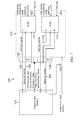
- Figure 1 is block diagram of a launch vehicle testing system according to one embodiment.
- FIG 2 is block diagram of a redundant electronic control module according to one embodiment employed in the launch vehicle testing system of Figure 1 .
- a launch vehicle testing system includes a non-flight test section operatively coupled to a flight control section of the launch vehicle.
- the non-flight test section supports flight circuit testing and troubleshooting in the flight control section through physical communication interfaces that are available without reconfiguring connections to flight hardware. This provides for complex failure mechanisms to be fault isolated in a quick and expeditious manner with minimal delay, allowing for launch-on-time requirements to be met.
- the non-flight test section includes a pair of redundant electronic control modules that communicate with flight system electronics in the flight control section.
- the redundant control modules and embedded software control mechanisms provide the capability to identify when a non-flight hardware error has occurred, and allows isolation to a specific control module that was the cause of the error.
- Flight hardware automatic reconfiguring of the redundant control module not in error allows for seamless flight system initialization and operation during pre-launch count downs.
- multiple redundant copies of flight software can be stored in the control modules so that a single error in will not cause a failure of the flight system software to initialize.
- the control modules allow connection to the flight hardware in a fashion that supports evolution of the internal capability of the modules with no impact to the flight hardware or software implementation.
- the control modules can be encapsulated with a protective material to avoid any mechanical difficulties during launch and flight resulting from high vibrations and temperatures.
- the flight control section includes highly reliable and radiation hardened electronics used for flight navigation and control in a harsh radiation environment such as outer space. All signals that support the control modules in the non-flight test section are controlled by a radiation hardened processor that performs the processing for the flight. In addition, the interfaces that buffer the flight control section from the non-flight control modules are radiation tolerant.
- the non-flight test section can be constructed with commercial off the shelf (COTS) hardware that does not require space flight qualification. This is because the non-flight test section is isolated and powered down during flight as the interfaces of the non-flight test section are not required to operate in flight. Furthermore, the enabling of the signals to communicate to flight hardware are controlled exclusively by flight hardware to assure the flight system is the only method to allow the COTS devices to operate and influence the flight hardware/software. External hardwired signals also support assuring the flight hardware has adequate information to avoid test functions when the test function is undesirable. Thus, the parts selection and manufacturing techniques for the non-flight test section do not require space flight or radiation environment operation. This means more advanced and state of the art embedded processors, which are typically not used in harsh radiation environments, can be employed. This allows heritage and new space flight systems to interface with more advanced hardware for troubleshooting support than would be possible if only space qualified hardware could be utilized.
- COTS commercial off the shelf
- a bootstrap is provided by delaying the reset to the flight hardware to allow the electronic control modules to initialize the lower memory in a dual port memory.
- a watchdog timer can be used on the flight equipment to allow start-up from the secondary electronic control module for the case of an electronic control module failure to properly configure the lower memory locations in the dual port memory.
- the flight processor and electronic control module then handshake through the dual port memory to complete initializing and then testing the flight hardware. This can allow test code to be completely separated from flight code with the "final" initialization configuring the flight software.
- Non-flight functions can include state-of-the-art processors, non-volatile storage, fast memory, and unique interfaces (such as Ethernet, firewire, etc.) to increase the bandwidth of ground support equipment (GSE) communication.
- GSE ground support equipment
- the flight equipment needs to receive the command to disable the GSE. After receiving this command, the flight computer powers-off the devices that are buffered to isolate powered-off signals from flight signals.
- the flight software also has the capability to re-enable the GSE (including re-application of power) in order to support a launch abort to utilize the GSE interface as part of an orderly launch abort, which can occur late enough in the count down sequence to have been after the GSE was disabled and powered down.
- the present approach allows flight system faults to be isolated away from non-flight system faults during factory testing and also during flight vehicle integration. This means, for example, that if the GSE interface to the flight system fails to function properly, the redundancy provided by the control modules allow fault isolation to either the non-flight or flight system hardware.
- GSE high speed commercial buses Ethernet, firewire, etc.
- the full capability of the flight system's debug tools is provided without having to change or add any connections to the flight system while it is installed on the launch vehicle.
- Factory testing is greatly enhanced with the more reliable interfaces provided by the present test system, which provides the possibility to purge and replace failing (non-flight) hardware without the requirement to do lengthy and costly failure analysis efforts to find exact root cause. Since the hardware in the non-flight test section is considered ground support equipment interfaces only, upon failure the hardware can be purged from a unit and replaced with new hardware.
- the full flight system embedded processor's debug interface is included in the electronic control module, which provides a more reliable test and debug interface for investigating factory test failures.
- the inclusion of the ability to stream raw sensor data out of the flight system through the electronic control module's high speed interface provides a previously unavailable ability to store sensor data for diagnostics of various factory test failures involving sensors.
- the system architecture can treat the electronic control modules as a primary/redundant function or can communicate to both electronic control module interfaces for each command/response.
- the command when a command is sent by the GSE to the flight system, the command can be sent to both control modules simultaneously. If both control modules receive the command without error, both will issue their own interrupt to the flight system.
- the flight software receives both interrupts and processes the command by running a special interrupt service routine which includes reading a message. If both control modules report the same valid status (in their respective dual port memory locations), the command will be serviced by flight hardware including a response back to GSE across each interface channel.
- the flight processor can just update status after validating the message. Any errors, such as a mis-compare of the two control modules by the flight software, can be handled in a user determined fashion by the flight software but will likely include status transmission across the electronic control module channels back to the GSE.
- a request by the GSE to read flight data or any other request of available flight system status has the flight system software provide the response to either control module or both depending on user defined functionality.
- Test functions not needed for launch operations can function using a primary/redundant electronic control module architecture and arm/fire or external signals to assure the test functions cannot be activated inadvertently.
- a failure of the default (selected) control module to communicate to the flight software will cause the flight software to respond/acknowledge the GSE message/requires on the other control module including a response that includes any available diagnostics data associated with the primary control module fault. This improves reliability for communication to the flight system from test equipment and ground support equipment allowing for better debug and analysis of communication/initialization, and test mode errors.
- the processors used in the present system can be implemented using software, firmware, hardware, or any appropriate combination thereof, as known to one of skill in the art.
- hardware components for the processor can include one or more microprocessors, memory elements, digital signal processing (DSP) elements, interface cards, and other standard components. Any of the foregoing may be supplemented by, or incorporated in, specially-designed application-specific integrated circuits (ASICs) or field programmable gate arrays (FPGAs).
- ASICs application-specific integrated circuits
- FPGAs field programmable gate arrays
- the processor includes or functions with software programs, firmware, or other computer readable instructions for carrying out various process tasks, calculations, and control functions, used in the present method. These instructions are typically tangibly embodied on any appropriate computer program product that includes a computer readable medium used for storage of computer readable instructions or data structures.
- Suitable computer readable media may include storage or memory media such as magnetic or optical media.
- storage or memory media may include conventional hard disks, volatile or non-volatile storage media such as Random Access Memory (RAM) (including, but not limited to, Synchronous Dynamic Random Access Memory (SDRAM), Double Data Rate (DDR) RAM, RAMBUS Dynamic RAM (RDRAM), Static RAM (SRAM), and the like), Read Only Memory (ROM), Electrically Erasable Programmable ROM (EEPROM), flash memory, compact disks (CDs), DVDs, Blu-ray disks, and the like. Combinations of the above are also included within the scope of computer readable media.
- RAM Random Access Memory
- SDRAM Synchronous Dynamic Random Access Memory
- DDR Double Data Rate
- RDRAM RAMBUS Dynamic RAM
- SRAM Static RAM
- EEPROM Electrically Erasable Programmable ROM
- flash memory compact disks (CDs), DVDs, Blu-ray disks, and the like. Combinations of the above are also included within the scope of computer
- FIG. 1 is block diagram of a launch vehicle testing system 100 according to one embodiment, which has a redundant fault isolation architecture.
- the testing system 100 generally includes an "in field" non-flight test section 110 that is operatively coupled to a flight control section 120, which in one embodiment includes standard radiation hardened, space qualified flight electronics.
- the non-flight test section 110 includes a pair of redundant electronic control modules (ECMs) 112 and 114 that are in operative communication with flight control section 120.
- ECMs electronice control modules
- the control modules 112 and 114 each have the same electronic components, and operate at the same time without regard or synchronization to each other.
- both control modules 112 and 114 operate the same embedded software code.
- the control modules 112 and 114 can be operatively coupled to ground support equipment for testing a launch vehicle through respective high speed commercial serial interfaces such as Ethernet connectors.
- the control modules 112 and 114 are powered on by isolated power supplies that can be turned off prior to launch. Further detail with respect to the control modules is described hereafter with respect to Figure 2 .
- Figure 1 also illustrates the basic connections between non-flight test section 110 and flight control section 120.
- a first voltage translation buffer (VTB) 132 is operatively coupled between control module 112 and the flight electronics in flight control section 120.
- a second voltage translation buffer 134 is operatively coupled between control module 114 and the flight electronics in flight control section 120.
- the voltage translation buffers 132 and 134 have dual power, with the flight control side of the buffers powered by hardware in flight control section 120.
- the voltage translation buffers 132 and 134 are configured to isolate the flight hardware from control modules 112 and 114 that are unpowered during a flight mode.
- the flight control section 120 provides a discrete/command to the voltage translation buffer 132 to enable the control module 112 only at power-on.
- the non-flight test section 110 can be implemented with components that will meet the thermal requirements of flight control section 120 while on the ground for pre-flight use.
- the non-flight test section 110 does not function during flight, primarily due to the space radiation environment. This requires non-flight test section 110 to be powered down before the launch vehicle is in the harsher space radiation environment.
- the flight control section 120 controls this power application and removal so that it can also reapply power for debug use and potential launch abort scenarios that occur after the non-flight test section 110 is powered off just before launch. Since any Ethernet connections are off at this time, the command to turn the non-flight test section 110 back to the "on" state is provided by a flight communication interface that is independent of non-flight test section 110.
- the flight communication interface commands the flight system software to issue a control signal to turn non-flight test section 110 back on to provide communication to ground equipment during this situation.
- a flight system control discrete which is under flight software control, can be sent from output F of flight control section 120 to turn on the hardware of non-flight test section 110 by actuating a flight hardware switch 142 to provide power from the flight system.
- control module 112 for the non-flight test section.
- control module 114 includes the same components as shown in Figure 2 for control module 112. These components include a processor 202 such as a microcontroller, which is operatively coupled to a first memory unit 204 such as a non-volatile memory storage for storing the electronic control module and the flight processor software, a second memory unit 206 such as a dual port memory (SRAM) for providing a data robust command response communication protocol through shared memory, and a third memory unit 208 (e.g., SDRAM) to utilize fast operating memory to allow a commercial processor to maximize throughput.
- processor 202 such as a microcontroller
- first memory unit 204 such as a non-volatile memory storage for storing the electronic control module and the flight processor software
- second memory unit 206 such as a dual port memory (SRAM) for providing a data robust command response communication protocol through shared memory
- SRAM dual port memory
- third memory unit 208 e.g., SDRAM
- the processor 202 is in operative communication with a commercial serial interface 210 such as a Universal Serial Bus (USB) connector.
- a high speed serial interface 212 operatively couples processor 202 to a high speed network connector 214 such as an Ethernet connector for communicating an Ethernet network.
- the control module 112 also provides the physical layer for high speed serial interface 212 to perform the PHY functions.
- a clock 216 such as a crystal or oscillator is also operatively coupled to processor 202 to provide timing signals.
- a configuration module 218 is operatively coupled to processor 202 and provides configuration information such as what memory to boot from, what functions of the complex commercial processor are active, power saving information such as sleep modes, etc.
- the processor 202 is further configured for simulation/system emulation input and system data collection output. The processor 202 also transmits interrupt/discrete signals to the flight system.
- a flight processor test interface 220 is in operative communication with processor 202 and is configured to provide for flight system test and debug.
- a commercial test and debug interface 222 is in operative communication with non-flight test section 110 and is configured to utilize the commercial processor's test interface (JTAG) to allow the processors to be controlled for development and test.
- JTAG commercial processor's test interface
- the control module 112 can be covered with a protective material 230 to provide protection from vibration and shock environments.
- exemplary methods that can be employed to cover the control module with the protective covering include plastic encapsulation, conformal coating, or epoxy bonding.
- an interrupt signal 150 is sent from an output H of control module 112 to an input A of flight control section 120.
- the interrupt signal 150 indicates that control module 112 has data/command ready for the flight system.
- the interrupt signal 150 can be sent via a dual port memory in control module 112 such as memory unit 206 ( Fig. 2 ).
- An interrupt signal 152 sent from an output K of control module 114 to an input B of flight control section 120 indicates that control module 114 has data/command ready for the flight system.
- the interrupt signal 152 can be sent via a general purpose input/output in control module 114.
- Select and control signals 154 are sent from an output C of flight control section 120 to an input I of control module 112.
- the signals 154 include dedicated signals required to enable the interface of only control module 112 with flight control section 120.
- select and control signals 156 are sent from an output E of flight control section 120 to an input M of control module 114.
- the select and control signals 156 include dedicated signals required to enable the interface of only control module 114 with flight control section 120. Signals are also provided to allow the flight processor to initiate the electronic control module communication to the GSE.
- An interface D of flight control section 120 provides for multiple signals (some unrelated to each other), in which some signals are bidirectional and others are unidirectional. These signals are grouped together because of one common characteristic, that is, they are sourced and received by both control module 112 at an interface J and control module 114 at an interface L.
- the multiple signals include shared data, control, address, simulation data, flight processor test interface, and reset.
- the shared data can be sent with a bidirectional interface and provides a mechanism for the flight system to write/read to/from the dual port memory in the control modules 112 and 114.
- Various control signals provide read enable, etc., which can also be used for communication between the flight system and the dual port memory in the control modules 112 and 114.
- the address data is sent from the flight system only, and is the address utilized to select a specific address in the selected control module to be read or written to in the dual port memory.
- the simulation data is bidirectional depending on mode. For example, in a simulation mode, simulation and emulator system data is transmitted into the flight system, whereas in a sensor monitor mode, sensor data is transmitted out of the flight system down to ground support equipment.
- Only the selected control module will issue commands to the flight system via the flight processor test interface.
- the flight system response to the signal from the flight processor test interface can be to both control modules 112 and 114 simultaneously or individually under flight system user control.
- the flight system generates the reset signals, and control modules 112, 114 will initialize to the proper operational mode depending on the input discrete(s) to control modules 112 and 114.
- a discrete signal 160 is input into control module 112, and a discrete signal 162 is input into control module 114.
- the discrete signals include external control for special modes, such as simulation/emulation modes, flight software write enable access, and self-identification for the control modules (e.g., software within a control module can determine if it is a primary or backup control module).
- the discrete signals also allow for unique software roles/functionality between the two control modules if that is determined to be required by use implementation.
- the discrete signals are not under flight system control. Rather, these signals are either hard discretes tied to proper state by implementation of Single Board Computer (SBC), such as for self-identification, or they control modes and are level discrete signals coming from external equipment.
- SBC Single Board Computer
- the signals sourced by both control modules 112 and 114 only get driven to the flight control section 120 through the voltage translation buffers 132 and 134 when the flight system selects that particular control module through signals 154 or 156 from outputs C or E (which are mutually exclusive of each other).
- the flight system can only have data driven to it from one of control modules at a time (the selected one). It should be noted that the flight system can respond/write to both control modules 112 and 114 at the same time interval, allowing for redundant responses across Ethernet channels, but can only receive data from the selected control module.
- each control module serves as a multiple data type communication path/interconnect between the flight system and the non-flight test section, primarily for the purpose of receiving commands and data uploads and for responding to commands with the proper reply data. Use of the Ethernet for telemetry interface is also supported.
- a minimum of a two sets/blocks can be reserved in the dual port memory to support command response communication.
- One set is for inbound GSE to flight system messages, and the other is for outbound flight system to GSE message/status/response.
- the control module passes commands to the flight system software by use of the inbound mailboxes.
- the flight software receives an interrupt anytime the control module receives a new command across the Ethernet.
- the flight software can poll the inbound mailbox on a periodic basis for newly received commands requiring a response.
- Support for flight system message/status/response is provided by the outbound mailboxes.
- the control module embedded software supports a polling of the outbound mailboxes in order to provide capability to periodically output flight system messages/status/response. Any communication protocol developed between the flight and non-flight systems utilizes the inbound/outbound mailbox structure to control data flow between the two systems.
- the boot section of the dual port memory (where the control module places flight system boot code) is coincident with the flight system reset/initialization vector memory location such that the flight system is able to operate out of the dual port memory with no additional control mechanism provided.
- the size of the dual port memory boot section is of sufficient depth to allow execution of flight code without use of any communication between the control module and the flight system for bootstrap functions.
- Example 1 includes a system for testing a launch vehicle, the system comprising: a flight control section including flight electronics in the launch vehicle; and a non-flight test section operatively coupled to the flight control section, the non-flight test section comprising a first electronic control module in operative communication with the flight electronics, and a second electronic control module that provides redundancy with respect to the first electronic control module, the second electronic control module in operative communication with the flight electronics.
- a first network serial interface is communicatively coupled to the first electronic control module and configured to provide signal communication between the first electronic control module and ground support equipment.
- a second network serial interface is communicatively coupled to the second electronic control module and configured to provide signal communication between the second electronic control module and the ground support equipment. Only one of the first and second electronic control modules is selected at a given point in time to send data to the flight control section. When a non-flight hardware error occurs in the selected electronic control module, the other electronic control module is automatically selected to send data to the flight control section.
- Example 2 includes the system of Example 1, wherein the flight electronics are radiation hardened, space qualified electronics.
- Example 3 includes the system of any of Examples 1-2, further comprising a first voltage translation buffer operatively coupled between the first electronic control module and the flight electronics, and a second voltage translation buffer operatively coupled between the second electronic control module and the flight electronics.
- the first and second voltage translation buffers are configured to isolate the flight electronics from the first and second electronic control modules during flight of the vehicle.
- Example 4 includes the system of any of Examples 1-3, wherein the first and second electronic control modules each comprise a processor, a first memory unit operatively coupled to the processor and including a non-volatile memory storage, a second memory unit operatively coupled to the processor and including a dual port memory, and a third memory unit operatively coupled to the processor and including an operating system memory.
- the first and second electronic control modules each comprise a processor, a first memory unit operatively coupled to the processor and including a non-volatile memory storage, a second memory unit operatively coupled to the processor and including a dual port memory, and a third memory unit operatively coupled to the processor and including an operating system memory.
- Example 5 includes the system of Example 4, wherein the processor in each of the first and second electronic control modules is in operative communication with a respective serial interface connector.
- Example 6 includes the system of any of Examples 4-5, wherein the processor in each of the first and second electronic control modules is operatively coupled to a flight processor test interface.
- Example 7 includes the system of any of Examples 1-6, wherein the first and second network serial interfaces are Ethernet connectors.
- Example 8 includes the system of any of Examples 1-7, wherein the first and second electronic control modules are covered with a protective material that provides protection from vibration and shock.
- Example 9 includes the system of any of Examples 1-8, wherein the flight control section is configured to control power application to the non-flight test section when needed prior to launch of the vehicle.
- Example 10 includes the system of any of Examples 1-9, wherein the first and second electronic control modules are configured to receive discrete signals from outside of the system.
- Example 11 includes the system of any of Examples 1-10, wherein the non-flight test section is configured to be powered down during flight of the launch vehicle.
- Example 12 includes the system of any of Examples 1-11, wherein the first and second electronic control modules are configured to receive select and control signals from the flight control section.
- Example 13 includes the system of any of Examples 1-12, wherein the first and second electronic control modules are configured to send interrupt signals to the flight control section.
- Example 14 includes the system of any of Examples 1-13, wherein the first and second electronic control modules are configured to receive or send a plurality of signals comprising shared data, control, address, simulation data, flight processor test interface data, and reset.
- Example 15 includes a method for testing a launch vehicle, the method comprising: providing a non-flight test section operatively coupled to a flight control section of the launch vehicle, the non-flight test section comprising a first electronic control module in operative communication with the flight electronics, and a second electronic control module that provides redundancy with respect to the first electronic control module, the second electronic control module in operative communication with the flight electronics; providing a first network serial interface communicatively coupled to the first electronic control module; providing a second network serial interface communicatively coupled to the second electronic control module; selecting one of the first and second electronic control modules at a given point in time to send data to the flight control section; and when a non-flight hardware error occurs in the selected electronic control module, selecting the other electronic control module to send data to the flight control section.
- Example 16 includes the method of Example 15, wherein the first and second network serial interfaces are connected to high-speed commercial media.
- Example 17 includes the method of any of Examples 15-16, wherein the first and second network serial interfaces are connected to an Ethernet network.
- Example 18 includes the method of any of Examples 15-17, wherein the flight control section controls power application to the non-flight test section when needed prior to launch of the vehicle.
- Example 19 includes the method of any of Examples 15-18, wherein the first and second electronic control modules receive discrete signals from ground support equipment.
- Example 20 includes the method of any of Examples 15-19, further comprising powering down the non-flight test section during flight of the launch vehicle.
Landscapes
- Engineering & Computer Science (AREA)
- Theoretical Computer Science (AREA)
- General Engineering & Computer Science (AREA)
- Quality & Reliability (AREA)
- Physics & Mathematics (AREA)
- General Physics & Mathematics (AREA)
- Computer Hardware Design (AREA)
- Debugging And Monitoring (AREA)
- Test And Diagnosis Of Digital Computers (AREA)
- Mobile Radio Communication Systems (AREA)
Applications Claiming Priority (1)
| Application Number | Priority Date | Filing Date | Title |
|---|---|---|---|
| US13/611,296 US9665453B2 (en) | 2012-09-12 | 2012-09-12 | Launch vehicle testing system |
Publications (2)
| Publication Number | Publication Date |
|---|---|
| EP2709014A2 true EP2709014A2 (de) | 2014-03-19 |
| EP2709014A3 EP2709014A3 (de) | 2017-03-29 |
Family
ID=49231243
Family Applications (1)
| Application Number | Title | Priority Date | Filing Date |
|---|---|---|---|
| EP13183049.9A Withdrawn EP2709014A3 (de) | 2012-09-12 | 2013-09-04 | Fahrzeugstart-Testsystem |
Country Status (3)
| Country | Link |
|---|---|
| US (1) | US9665453B2 (de) |
| EP (1) | EP2709014A3 (de) |
| JP (1) | JP2014058302A (de) |
Families Citing this family (13)
| Publication number | Priority date | Publication date | Assignee | Title |
|---|---|---|---|---|
| CN104298230B (zh) * | 2014-10-20 | 2016-09-21 | 北京宇航系统工程研究所 | 一种多智能体分布式冗余协调运载火箭动力测控系统 |
| CN107770100B (zh) * | 2017-10-16 | 2019-12-20 | 中国运载火箭技术研究院 | 一种测发控冗余网络架构及冗余方法 |
| JP7049879B2 (ja) * | 2018-03-23 | 2022-04-07 | 三菱重工業株式会社 | 制御システム及びロケット |
| KR102221445B1 (ko) * | 2019-11-22 | 2021-03-02 | 주식회사 이노템즈 | 비행 추진체 제어용 통신 테스트 장치 |
| CN111006550A (zh) * | 2019-11-29 | 2020-04-14 | 上海宇航系统工程研究所 | 一种基于分布式采集的运载火箭的综合测量单元 |
| CN111288846B (zh) * | 2020-05-13 | 2020-08-04 | 蓝箭航天空间科技股份有限公司 | 一种运载火箭发射支持等效装置及控制系统 |
| CN112312355B (zh) * | 2020-10-10 | 2023-11-17 | 中国运载火箭技术研究院 | 一种箭载以太网通信方法及通信系统 |
| CN113766676B (zh) * | 2021-08-19 | 2024-04-19 | 湖北航天技术研究院总体设计所 | 一种基于无线自组网的运载器电气系统及其组网方法 |
| CN113945402B (zh) * | 2021-08-30 | 2023-06-06 | 北京宇航系统工程研究所 | 一种气驱分离装置地面试验系统 |
| CN117910189B (zh) * | 2022-10-12 | 2025-09-09 | 北京宇航系统工程研究所 | 一种热发射起飞段飞行时序设计方法、设备和存储介质 |
| CN116582388A (zh) * | 2023-05-22 | 2023-08-11 | 湖北航天技术研究院总体设计所 | 运载火箭分离后尾段部分的通信方法及装置 |
| CN117392897A (zh) * | 2023-10-31 | 2024-01-12 | 安胜(天津)飞行模拟系统有限公司 | 飞行模拟器配置更换方法、装置、设备和存储介质 |
| CN119902517B (zh) * | 2025-03-28 | 2025-07-22 | 北京星途探索科技有限公司 | 一种运载火箭的时序测试装置、方法及介质 |
Family Cites Families (35)
| Publication number | Priority date | Publication date | Assignee | Title |
|---|---|---|---|---|
| US3305671A (en) * | 1962-09-28 | 1967-02-21 | United Aircraft Corp | System for bounding the radius coordinate of an orbiting vehicle |
| US5271582A (en) * | 1990-06-29 | 1993-12-21 | Standard Space Platforms Corp. | Modular mother satellite bus for subsidiary payloads |
| US5206455A (en) * | 1991-03-28 | 1993-04-27 | Quantic Industries, Inc. | Laser initiated ordnance systems |
| US6157621A (en) * | 1991-10-28 | 2000-12-05 | Teledesic Llc | Satellite communication system |
| DE69525495T2 (de) * | 1994-07-22 | 2002-10-31 | Hughes Electronics Corp., El Segundo | Satellitenkamera mit Bildebenenarray |
| US5927653A (en) * | 1996-04-17 | 1999-07-27 | Kistler Aerospace Corporation | Two-stage reusable earth-to-orbit aerospace vehicle and transport system |
| US5721431A (en) * | 1996-09-17 | 1998-02-24 | Institute For Space And Terrestrial Science | Satellite attitude sensor using thermal imaging |
| US6066850A (en) * | 1996-09-17 | 2000-05-23 | Canadian Space Agency | Satellite attitude sensor using thermal imaging |
| US6119985A (en) * | 1997-03-07 | 2000-09-19 | Pioneer Rocketplane Corporation | Reusable rocket-propelled high altitude airplane and method and apparatus for mid-air oxidizer transfer to said airplane |
| US6056237A (en) * | 1997-06-25 | 2000-05-02 | Woodland; Richard L. K. | Sonotube compatible unmanned aerial vehicle and system |
| US6237795B1 (en) * | 2000-05-26 | 2001-05-29 | The United States Of America As Represented By The Secretary Of The Airforce | Modular transport container for satellites |
| CA2416373C (en) * | 2000-07-20 | 2007-07-17 | Viraf S. Kapadia | System and method for transportation vehicle monitoring, feedback and control |
| US6598828B2 (en) * | 2001-03-05 | 2003-07-29 | The United States Of America As Represented By The Secretary Of The Navy | Integral data acquisition capacity |
| WO2002077660A2 (en) * | 2001-03-27 | 2002-10-03 | Space Launch Corporation | A system for the delivery and orbital maintenance of micro satellites and small space-based instruments |
| US6745004B2 (en) * | 2001-05-22 | 2004-06-01 | Northrop Grumman Corporation | Satellite frequency generation incorporating secondary power supply |
| US6845949B2 (en) * | 2002-07-23 | 2005-01-25 | The Boeing Company | System and methods for integrating a payload with a launch vehicle |
| US7025307B2 (en) * | 2002-12-13 | 2006-04-11 | The Boeing Company | Method and apparatus for solar tacking momentum maintenance in long-duration deployment of a large reflector |
| US7299315B2 (en) * | 2003-04-02 | 2007-11-20 | Nisca Corporation | Control device including connecting device for rewriting memory region |
| US7343232B2 (en) * | 2003-06-20 | 2008-03-11 | Geneva Aerospace | Vehicle control system including related methods and components |
| US7484693B2 (en) * | 2003-09-17 | 2009-02-03 | The Boeing Company | Centralized bus interface with single wire secondary distribution |
| US6845939B1 (en) * | 2003-10-24 | 2005-01-25 | G. Douglas Baldwin | Tailboom-stabilized VTOL aircraft |
| US7302364B2 (en) * | 2004-07-30 | 2007-11-27 | The Boeing Company | Methods and systems for advanced spaceport information management |
| US20060174051A1 (en) | 2005-02-02 | 2006-08-03 | Honeywell International Inc. | Method and apparatus for a redundancy approach in a processor based controller design |
| US20070129902A1 (en) * | 2005-08-05 | 2007-06-07 | Orbell Richard | Electronic module mounting means |
| US20070049204A1 (en) * | 2005-08-23 | 2007-03-01 | The Boeing Company | Wireless spacecraft operational and testing communications network |
| US20100096491A1 (en) * | 2006-10-02 | 2010-04-22 | Rocket Racing, Inc. | Rocket-powered entertainment vehicle |
| US20080316784A1 (en) * | 2007-06-22 | 2008-12-25 | Cebry George L | Isolated radiation hardened electronics on/off control circuit |
| US8100018B2 (en) * | 2009-02-06 | 2012-01-24 | Kulite Semiconductor Products, Inc. | Pressure transducers employing radiation hardened electronics |
| US8364857B2 (en) * | 2009-08-31 | 2013-01-29 | Qualcomm Incorporated | Wireless modem with CPU and auxiliary processor that shifts control between processors when in low power state while maintaining communication link to wireless network |
| US8540183B2 (en) * | 2009-12-12 | 2013-09-24 | Heliplane, Llc | Aerovehicle system including plurality of autogyro assemblies |
| US10607742B2 (en) * | 2011-05-09 | 2020-03-31 | National Institute Of Aerospace Associates | Radiation shielding materials containing hydrogen, boron and nitrogen |
| US9273634B2 (en) * | 2011-08-18 | 2016-03-01 | Patrick R. E. Bahn | Rocket stage and method of improving an existing rocket stage |
| US20130132878A1 (en) * | 2011-09-02 | 2013-05-23 | Adobe Systems Incorporated | Touch enabled device drop zone |
| US9026410B2 (en) * | 2012-03-16 | 2015-05-05 | The Boeing Company | System and method for rapid management of logic formulas |
| US8868258B2 (en) * | 2012-08-06 | 2014-10-21 | Alliant Techsystems, Inc. | Methods and apparatuses for autonomous flight termination |
-
2012
- 2012-09-12 US US13/611,296 patent/US9665453B2/en not_active Expired - Fee Related
-
2013
- 2013-09-04 EP EP13183049.9A patent/EP2709014A3/de not_active Withdrawn
- 2013-09-06 JP JP2013184796A patent/JP2014058302A/ja not_active Withdrawn
Non-Patent Citations (1)
| Title |
|---|
| None |
Also Published As
| Publication number | Publication date |
|---|---|
| US9665453B2 (en) | 2017-05-30 |
| EP2709014A3 (de) | 2017-03-29 |
| US20140074347A1 (en) | 2014-03-13 |
| JP2014058302A (ja) | 2014-04-03 |
Similar Documents
| Publication | Publication Date | Title |
|---|---|---|
| US9665453B2 (en) | Launch vehicle testing system | |
| CN107347018B (zh) | 一种三冗余1553b总线动态切换方法 | |
| US11507718B1 (en) | Chip verification system and verification method therefor | |
| KR102914332B1 (ko) | 시스템 온 칩 및 이의 리셋 제어 방법 | |
| EP3420462B1 (de) | Busbrücke zur übersetzung von anfragen zwischen einem modulbus und einem axi-bus | |
| US8880768B2 (en) | Storage controller system with data synchronization and method of operation thereof | |
| US12001288B2 (en) | Devices and methods for safe mode of operation in event of memory channel misbehavior | |
| JP6435101B2 (ja) | 揮発性シャドウメモリを介した不揮発性メモリへのアクセス | |
| US11409538B2 (en) | Data processing system and method for configuring and operating a data processing system | |
| US20150242266A1 (en) | Information processing apparatus, controller, and method for collecting log data | |
| EP3279796B1 (de) | Ressourcenzugangsverwaltungskomponente und verfahren dafür | |
| US20220113353A1 (en) | Input-output device with debug controller | |
| US8954639B2 (en) | Integrated link calibration and multi-processor topology discovery | |
| JP4299634B2 (ja) | 情報処理装置及び情報処理装置の時計異常検出プログラム | |
| US20030159102A1 (en) | Method for testing a universal serial bus host controller | |
| US20210286694A1 (en) | Packeted protocol device test system | |
| CN114443545B (zh) | 一种接口拓展方法、装置、管理系统和相关设备 | |
| US9081743B2 (en) | Communication system and communicaton method | |
| KR102154245B1 (ko) | 인공위성 내 소프트웨어 기반 재설정 유닛 | |
| JP2021036425A (ja) | テスト機能を持つ装置およびそのテストの方法 | |
| US9836364B2 (en) | In-band recovery mechanism for I/O modules in a data storage system | |
| US20250199918A1 (en) | Non-transitory computer readable medium, co-simulation method, and co-simulation apparatus | |
| JP5516402B2 (ja) | 情報処理装置及び情報処理装置の制御方法 | |
| Eickhoff | Onboard computer main elements | |
| JP2018025840A (ja) | 分散シミュレーションシステム、分散シミュレーション手法 |
Legal Events
| Date | Code | Title | Description |
|---|---|---|---|
| PUAI | Public reference made under article 153(3) epc to a published international application that has entered the european phase |
Free format text: ORIGINAL CODE: 0009012 |
|
| 17P | Request for examination filed |
Effective date: 20130904 |
|
| AK | Designated contracting states |
Kind code of ref document: A2 Designated state(s): AL AT BE BG CH CY CZ DE DK EE ES FI FR GB GR HR HU IE IS IT LI LT LU LV MC MK MT NL NO PL PT RO RS SE SI SK SM TR |
|
| AX | Request for extension of the european patent |
Extension state: BA ME |
|
| RAP1 | Party data changed (applicant data changed or rights of an application transferred) |
Owner name: HONEYWELL INTERNATIONAL INC. |
|
| PUAL | Search report despatched |
Free format text: ORIGINAL CODE: 0009013 |
|
| AK | Designated contracting states |
Kind code of ref document: A3 Designated state(s): AL AT BE BG CH CY CZ DE DK EE ES FI FR GB GR HR HU IE IS IT LI LT LU LV MC MK MT NL NO PL PT RO RS SE SI SK SM TR |
|
| AX | Request for extension of the european patent |
Extension state: BA ME |
|
| RIC1 | Information provided on ipc code assigned before grant |
Ipc: G06F 11/22 20060101AFI20170221BHEP Ipc: G06F 11/16 20060101ALI20170221BHEP |
|
| 17Q | First examination report despatched |
Effective date: 20170321 |
|
| STAA | Information on the status of an ep patent application or granted ep patent |
Free format text: STATUS: THE APPLICATION IS DEEMED TO BE WITHDRAWN |
|
| 18D | Application deemed to be withdrawn |
Effective date: 20170801 |