EP2709152A2 - Circuit de refroidissement doté d'un échangeur de chaleur dimensionné suffisamment juste - Google Patents
Circuit de refroidissement doté d'un échangeur de chaleur dimensionné suffisamment juste Download PDFInfo
- Publication number
- EP2709152A2 EP2709152A2 EP13181199.4A EP13181199A EP2709152A2 EP 2709152 A2 EP2709152 A2 EP 2709152A2 EP 13181199 A EP13181199 A EP 13181199A EP 2709152 A2 EP2709152 A2 EP 2709152A2
- Authority
- EP
- European Patent Office
- Prior art keywords
- power electronics
- heat flow
- electronics module
- power
- flow
- Prior art date
- Legal status (The legal status is an assumption and is not a legal conclusion. Google has not performed a legal analysis and makes no representation as to the accuracy of the status listed.)
- Withdrawn
Links
Images


Classifications
-
- H—ELECTRICITY
- H10—SEMICONDUCTOR DEVICES; ELECTRIC SOLID-STATE DEVICES NOT OTHERWISE PROVIDED FOR
- H10W—GENERIC PACKAGES, INTERCONNECTIONS, CONNECTORS OR OTHER CONSTRUCTIONAL DETAILS OF DEVICES COVERED BY CLASS H10
- H10W40/00—Arrangements for thermal protection or thermal control
- H10W40/60—Securing means for detachable heating or cooling arrangements, e.g. clamps
- H10W40/611—Bolts or screws
-
- H—ELECTRICITY
- H05—ELECTRIC TECHNIQUES NOT OTHERWISE PROVIDED FOR
- H05K—PRINTED CIRCUITS; CASINGS OR CONSTRUCTIONAL DETAILS OF ELECTRIC APPARATUS; MANUFACTURE OF ASSEMBLAGES OF ELECTRICAL COMPONENTS
- H05K7/00—Constructional details common to different types of electric apparatus
- H05K7/20—Modifications to facilitate cooling, ventilating, or heating
- H05K7/2089—Modifications to facilitate cooling, ventilating, or heating for power electronics, e.g. for inverters for controlling motor
- H05K7/20927—Liquid coolant without phase change
-
- H—ELECTRICITY
- H10—SEMICONDUCTOR DEVICES; ELECTRIC SOLID-STATE DEVICES NOT OTHERWISE PROVIDED FOR
- H10W—GENERIC PACKAGES, INTERCONNECTIONS, CONNECTORS OR OTHER CONSTRUCTIONAL DETAILS OF DEVICES COVERED BY CLASS H10
- H10W40/00—Arrangements for thermal protection or thermal control
- H10W40/40—Arrangements for thermal protection or thermal control involving heat exchange by flowing fluids
- H10W40/47—Arrangements for thermal protection or thermal control involving heat exchange by flowing fluids by flowing liquids, e.g. forced water cooling
-
- H—ELECTRICITY
- H10—SEMICONDUCTOR DEVICES; ELECTRIC SOLID-STATE DEVICES NOT OTHERWISE PROVIDED FOR
- H10W—GENERIC PACKAGES, INTERCONNECTIONS, CONNECTORS OR OTHER CONSTRUCTIONAL DETAILS OF DEVICES COVERED BY CLASS H10
- H10W40/00—Arrangements for thermal protection or thermal control
- H10W40/60—Securing means for detachable heating or cooling arrangements, e.g. clamps
- H10W40/611—Bolts or screws
- H10W40/613—Bolts or screws for stacked arrangements of a plurality of semiconductor devices
-
- H—ELECTRICITY
- H10—SEMICONDUCTOR DEVICES; ELECTRIC SOLID-STATE DEVICES NOT OTHERWISE PROVIDED FOR
- H10W—GENERIC PACKAGES, INTERCONNECTIONS, CONNECTORS OR OTHER CONSTRUCTIONAL DETAILS OF DEVICES COVERED BY CLASS H10
- H10W40/00—Arrangements for thermal protection or thermal control
- H10W40/70—Fillings or auxiliary members in containers or in encapsulations for thermal protection or control
- H10W40/73—Fillings or auxiliary members in containers or in encapsulations for thermal protection or control for cooling by change of state
-
- H—ELECTRICITY
- H10—SEMICONDUCTOR DEVICES; ELECTRIC SOLID-STATE DEVICES NOT OTHERWISE PROVIDED FOR
- H10W—GENERIC PACKAGES, INTERCONNECTIONS, CONNECTORS OR OTHER CONSTRUCTIONAL DETAILS OF DEVICES COVERED BY CLASS H10
- H10W40/00—Arrangements for thermal protection or thermal control
- H10W40/40—Arrangements for thermal protection or thermal control involving heat exchange by flowing fluids
- H10W40/43—Arrangements for thermal protection or thermal control involving heat exchange by flowing fluids by flowing gases, e.g. forced air cooling
Definitions
- the invention relates to the field of heat dissipation of power electronics from a power electronics module, or a power electronics module having a converter, in particular by means of a thermosiphon cooling circuit.
- power electronics are often as semiconductor elements, for example, IGBT's, thyristors, diodes, resistors, MOSFETs, as well as combinations of such devices and the like to understand.
- the term power electronics hereinafter power electronics elements are understood, which typically have a reverse voltage of more than 500 volts during operation. These electrical and electronic elements must be cooled during operation, as they also generate very high heat flows due to the very high power densities, which must be dissipated efficiently.
- these power electronic elements are often grouped together in power modules.
- an inverter may be used to power an industrial mill, a vehicle, a ship, and / or generally for voltage conversion or voltage conversion.
- Heat exchanger to the primary cooling flow thermal power to be transmitted a critical size, because this size affects the need for volume for the accommodation of cooling ducts of sufficient cross-section, as well as pumps, fans and the like.
- the object of the invention is therefore to present an improved power electronics module and an improved converter with which lower construction volumes can be achieved in comparison with known power electronics modules or converters of the same power class.
- construction volume is understood to mean the space requirement with regard to its spatial, dimensionally dimensioned dimensions.
- Known power electronics modules have in operation sometimes not only a first operating state, but also a second operating state (or switching case), in which the electrical circuit of the power electronic elements is different from the first operating state. Accordingly, not only the first power electronic elements associated with the first switching case require thermal cooling, but also the power electronics elements associated with the second switching case.
- the first power electronics elements are often thermally connected to the first power electronics elements via first coolers for receiving the first heat flow, while the second power electronics elements are often thermally connected to the second power electronics elements via second coolers for receiving the second heat flow.
- the heat exchanger was typically designed thermally for a dissipatable heat flow, the sum of which amounts to corresponds to the maximum first heat flow and the maximum second heat flow.
- both the heat exchanger and the primary cooling flow with its channel elements and drive means for generating the primary cooling flow have been correspondingly dimensioned.
- a first advantage of such a power electronics module is that the heat exchanger requires a smaller overall volume than known heat exchangers of power electronics modules of the same power class. As a result, more compact power electronics modules can be achieved in terms of volume.
- a further advantage is that the heat exchanger according to the invention requires less power from the primary cooling flow compared to known heat exchangers of power electronics modules of the same power class.
- the required powers of the means for generating the primary current such as fans in the case of air cooling or a pump unit in the case of liquid cooling, such as water cooling, can be lowered.
- This allows, for example, the use of fans or pumps of a lower performance class than before. Such fans or pumps are not only often more compact, but also considerably less expensive than the higher-end-of-the-range types used to date.
- the secondary cooling circuit can be a liquid circuit in which the working medium essentially always remains in a liquid state, or else a thermosiphon cooling circuit in which the working medium evaporates in at least one evaporator and then condenses in a condenser and in liquid form is returned to the evaporator to go through the cycle again.
- the first radiator is formed by a first evaporator and the second radiator is formed by a second evaporator, wherein the heat exchanger has a condenser for liquefying a working medium of the secondary cooling circuit.
- the secondary cooling circuit is a thermosiphon cooling circuit, it is advantageous in terms of thermal efficiency, if the secondary cooling circuit in the form of a closed loop (as a loop-type thermosiphon) is formed.
- the first radiator is always arranged fluidically parallel to the second radiator in the cooling circuit.
- the first cooler and the second cooler are of the same type and therefore have approximately the same pressure drop across the cooler, ie between a first cooling connection (inlet) and a second cooling connection (outlet).
- Another advantage is that, unlike a serial arrangement of the radiator in the secondary circuit, both radiators receive a working medium of about the same inlet temperature and not one of a fluidly upstream cooler already preheated working fluid, so that the thermal efficiency is relatively higher.
- the second power electronics element differs from the first power electronics element, in particular differs in type. This is especially true when the first power electronics element and the second power electronics element are arranged and configured such that the maximum first heat flow occurs in a first operating state of the power electronics module, while the maximum second heat flow occurs in a second operating state of the power electronics module offset in time relative to the first operating state , Depending on the embodiment of the power electronics module, the first heat flow in the first operating state may be greater than the first heat flow in the second operating state and the second heat flow in the second operating state may be greater than the second heat flow in the first operating state.
- the primary cooling stream may be a liquid cooling stream having a water content or a gaseous cooling stream.
- a gaseous cooling flow this can be, for example, an exhaust gas flow or an air flow.
- the at least one power electronics module can be pushed into the converter like a drawer and pulled out of the converter, the heat exchanger being arranged on this power electronics module.
- the advantage is further increased if a converter has several such power electronics modules, which can be inserted in this way in the inverter and removed from this.
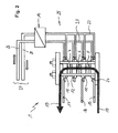
- FIG. 1 shows a first embodiment of a power electronics module 1 with three power electronic elements a first operating state.
- the power electronics module 1 has three power electronics elements, which are clamped together with several coolers to form a stack 3, while in FIG FIG. 2 a second operating state of the power electronics module 1 is shown.
- the power electronic element arranged bottommost in the stack 3 is the "first power electronic element” 5, while the power electronic element following in the vertical direction of the stack 3 is hereinafter referred to as "second power electronic element" 6.
- the uppermost in the stack 3 arranged, third power electronic element 7 may in turn be of the type of the first power electronic element 5 - but it must not necessarily.
- the second power electronics element 6 can have two switching positions, namely a passage of the nominal current in its first switching position and a blocking of the nominal current in its second switching position.
- the second power electronic element 6 In the first operating state of the power electronics module 1, the second power electronic element 6 is in the first switching position, while it is in the second operating position in the second operating state of the power electronics module 1 in the second switching position.
- the transition from the first operating state to the second operating state can take place very quickly, that is within a fraction of a second.
- the second power electronics element may, for example, be a snubber diode and a further semiconductor element which can protect the third power electronics element 7 and elements connected thereto from undesired damage as a result of an overvoltage, by changing the current flow entering the stack into another current path (mostly temporary) redirect.
- the structure of the stack 3 would be different then in FIG. 1 in that it would have conventional internal busbars and insulating pieces, so that the three power electronic elements 5, 6, 7 would no longer be electrically connected in series, as in FIG FIG. 1 and FIG. 2 shown. Since a more detailed description and description of the clarity of the present inventive idea would be detrimental, the highly simplified switching options of the power electronics module 1 is referred back.
- a first radiator 10 for receiving a heat flow of the first power electronic element 5 is arranged.
- a second radiator 11 is arranged, which serves both for receiving a heat flow of the first power electronic element 5, as well as a heat flow of the second power electronic element 6.
- a third radiator 12 is arranged, which serves both for receiving a heat flow of the second power electronic element 6, as well as a heat flow of the third power electronic element 7.
- a fourth cooler 13 is finally arranged, which also contributes to receiving a heat flow of the third power electronic element 7.
- Each radiator 10, 11, 12, 13 has a connection tab 24 for electrically tapping an electric current.
- the respective electrical current is not tapped off at all coolers, but only at the first cooler 10, which is electrically connected to an input busbar 15 on the second cooler, which is electrically connected to a bypass busbar 16 for this purpose is, and the fourth radiator 13, which is electrically connected to an output busbar 17.
- the second power electronic element 6 In the first operating state of the power electronics module 1, the second power electronic element 6 is in the first switching position, while it is in the second operating position in the second operating state of the power electronics module 1 in the second switching position.
- the second cruelektronikelement 6 can be understood as an electric double switch, which in both the first operating state, as well as in the second operating state of the power electronics module to explain the invention 1 generates a second heat flow, because a person skilled in the art knows how to form the mechanical structure of a stack concretely.
- the second power electronics element 6 thus blocks the current flow entering the stack 3 via the first cooler 10 through the stack on the second cooler 11, so that the flow of current feeds the stack 3 via the bypass busbar 16 along a first current path 18 leaves again.
- the second power electronic element 6 passes the current flow entering the stack 3 via the first cooler 10 through the second cooler 11 and through the third power electronics element 7 to the fourth cooler 13 and the output bus bar 16 along a second one Current path 19 and blocks the current path to the bypass busbar 16 electrically.
- Each cooler 10, 11, 12, 13 has a first cooling connection 20 and a second cooling connection 21, which are in each case fluidically connected to a heat exchanger 14 via a first pipe system 22 and a second pipe system 23, and thus a secondary cooling circuit 25 in the form of a closed loop form.
- the first pipe system 22 and the second pipe system 23 are at least partially electrically insulating, while the working fluid of the secondary cooling circuit is electrically insulating.
- the heat exchanger 14 transfers a predominant part of the sum of all heat flows absorbed by the coolers to a primary cooling stream 26 of a primary cooling system 27. If the primary cooling system is also a (closed) cooling circuit, the heat flow from the first pipe system 22 leaves the heat exchanger via a primary flow return 28th
- the secondary cooling circuit 25 is a thermosiphon cooling circuit in which a working medium evaporates in at least one of the evaporators acting as evaporator 10, 11, 12, 13 and then condensed in the heat exchanger 14 acting as a condenser and in liquid form the evaporators 10, 11, 12, 13 is returned to cycle again.
- the FIG. 3 shows a heat flow time diagram (Qt diagram) of the power electronics module in the transition from the first operating state to the second operating state.
- the first power electronic elements 5 is configured and arranged differently from the second power electronic elements 6 by the electrical switching behavior and the switching arrangement in the power electronics module 1. Accordingly different are the load characteristics the heat flows 29, 30 of the first power electronic elements 5 and the second power electronic elements 6th
- the first power electronics element 5 During operation of the power electronics module 1 in the first operating state at the time t1, the first power electronics element 5 generates a first heat flow 29, while the second power electronics element 6 generates a second heat flow 30.
- the first heat flow 29 and the second heat flow 30 are transferred to the primary cooling system 27 via the secondary circuit 25. Since the second power electronic element 6 blocks the first current flow 18 at this point in time t1 and redirects it in the direction of the bypass busbar 16, the second heat flow 30 is smaller in magnitude than the first heat flow 29.
- the first heat flow 29 is transferred via the coolers 10, 11 to the secondary circuit 25, while the second heat flow 30 is transmitted via the coolers 11, 12 to the secondary circuit 25.
- FIG. 4 shows the first power electronics element 5 during operation of the power electronics module 1 in the second operating state at time t2 a first heat flow 29, which is now lower in terms of amount than the first heat flow 29 in the first operating state.
- a first heat flow 29 which is now lower in terms of amount than the first heat flow 29 in the first operating state.
- the voltage across the power electronics module 1 now no longer drops alone across the first power electronics element 5, but in common across all the power electronics elements 5, 6, 7.
- the second power electronic elements 6 at this time t2 now passes the second current flow 19 in the direction of the outgoing busbar 17 and shuts off the first current path 18 in the direction of the bypass busbar 16, the second heat flow 30 is for the second operating state (at the instant t2). in terms of amount greater than in the first operating state (at time t1).
- the maximum first heat flow 29 (Q 29 (t1) at time t1) and the maximum second heat flow 30 (Q 30 (t2) at time t2) are summed up.
- the heat exchanger 14 was conventionally selected after this summary heat flow.
- the heat exchanger of its thermal performance can be made shorter than heretofore, because sufficient transfer of the first heat flow 29 and the second Heat flow 30 to the secondary circuit 25 reaches the cooling capacity according to the second operating state with Q 29 (t2) plus Q 30 (t2).
Landscapes
- Engineering & Computer Science (AREA)
- Microelectronics & Electronic Packaging (AREA)
- Physics & Mathematics (AREA)
- Thermal Sciences (AREA)
- Cooling Or The Like Of Semiconductors Or Solid State Devices (AREA)
- Inverter Devices (AREA)
- Cooling Or The Like Of Electrical Apparatus (AREA)
Applications Claiming Priority (1)
| Application Number | Priority Date | Filing Date | Title |
|---|---|---|---|
| DE202012008739U DE202012008739U1 (de) | 2012-09-12 | 2012-09-12 | Kühlkreislauf mit ausreichend knapp bemessenem Wärmetauscher |
Publications (2)
| Publication Number | Publication Date |
|---|---|
| EP2709152A2 true EP2709152A2 (fr) | 2014-03-19 |
| EP2709152A3 EP2709152A3 (fr) | 2017-11-29 |
Family
ID=49000856
Family Applications (1)
| Application Number | Title | Priority Date | Filing Date |
|---|---|---|---|
| EP13181199.4A Withdrawn EP2709152A3 (fr) | 2012-09-12 | 2013-08-21 | Circuit de refroidissement doté d'un échangeur de chaleur dimensionné suffisamment juste |
Country Status (4)
| Country | Link |
|---|---|
| US (1) | US9232685B2 (fr) |
| EP (1) | EP2709152A3 (fr) |
| CN (1) | CN103687441A (fr) |
| DE (1) | DE202012008739U1 (fr) |
Families Citing this family (4)
| Publication number | Priority date | Publication date | Assignee | Title |
|---|---|---|---|---|
| RU2650183C2 (ru) * | 2013-08-07 | 2018-04-11 | АББ С.п.А. | Охлаждающее устройство для электрического устройства и электрическое устройство, в частности автоматический выключатель, содержащий такое охлаждающее устройство |
| DE202013104510U1 (de) | 2013-10-04 | 2014-01-09 | Abb Technology Ag | Halbleiterstapel für Umrichter mit Snubber-Kondensatoren |
| CN112783299B (zh) * | 2019-11-06 | 2023-10-13 | 富联精密电子(天津)有限公司 | Lts散热器及具有该lts散热器的电子设备 |
| CA3128575C (fr) | 2021-08-18 | 2025-11-04 | Penno's Machining And Manufacturing Ltd. | Appareil pour charger et stocker de grosses balles agricoles |
Family Cites Families (33)
| Publication number | Priority date | Publication date | Assignee | Title |
|---|---|---|---|---|
| US5052472A (en) * | 1989-07-19 | 1991-10-01 | Hitachi, Ltd. | LSI temperature control system |
| US20030205363A1 (en) * | 2001-11-09 | 2003-11-06 | International Business Machines Corporation | Enhanced air cooling of electronic devices using fluid phase change heat transfer |
| US7187548B2 (en) * | 2002-01-16 | 2007-03-06 | Rockwell Automation Technologies, Inc. | Power converter having improved fluid cooling |
| DE10247333A1 (de) * | 2002-06-06 | 2003-12-24 | Abb Patent Gmbh | Mehrkanaldimmer |
| US6772603B2 (en) * | 2002-12-20 | 2004-08-10 | Ut-Battelle, Llc | Methods and apparatus for thermal management of vehicle systems and components |
| US7591302B1 (en) * | 2003-07-23 | 2009-09-22 | Cooligy Inc. | Pump and fan control concepts in a cooling system |
| DE10344631B4 (de) * | 2003-09-25 | 2013-12-24 | Robert Bosch Gmbh | Elektronische Schaltungsanordnung |
| US6952345B2 (en) * | 2003-10-31 | 2005-10-04 | Raytheon Company | Method and apparatus for cooling heat-generating structure |
| DE102004029901A1 (de) * | 2004-06-19 | 2006-01-12 | Christian-Albrechts-Universität Zu Kiel | Umrichter |
| US7187549B2 (en) * | 2004-06-30 | 2007-03-06 | Teradyne, Inc. | Heat exchange apparatus with parallel flow |
| JP2006242479A (ja) * | 2005-03-03 | 2006-09-14 | Toshiba Corp | 冷却装置及び電子機器 |
| EP1750360A1 (fr) * | 2005-08-03 | 2007-02-07 | ABB Research Ltd | Dispostif de convertisseur à plusieurs niveaux et son utilisation |
| CN101421576B (zh) * | 2006-04-13 | 2010-09-15 | 三菱电机株式会社 | 冷却装置以及电力变换装置 |
| EP2030494A4 (fr) * | 2006-06-22 | 2011-08-31 | Abb Technology Ltd | Dispositif et procédé de refroidissement |
| US20070297136A1 (en) * | 2006-06-23 | 2007-12-27 | Sun Micosystems, Inc. | Modular liquid cooling of electronic components while preserving data center integrity |
| US20080310112A1 (en) * | 2007-06-13 | 2008-12-18 | Johnson Controls Technology Company | System and Method for Providing Dewpoint Control in an Electrical Enclosure |
| JP4216319B2 (ja) * | 2007-06-19 | 2009-01-28 | ファナック株式会社 | インバータ筐体の冷却構造 |
| US7957166B2 (en) * | 2007-10-30 | 2011-06-07 | Johnson Controls Technology Company | Variable speed drive |
| US8556011B2 (en) * | 2007-11-01 | 2013-10-15 | GM Global Technology Operations LLC | Prediction strategy for thermal management and protection of power electronic hardware |
| US9342121B2 (en) * | 2008-05-06 | 2016-05-17 | International Business Machines Corporatoin | Cooling system for electronic components |
| EP2175484A1 (fr) * | 2008-10-07 | 2010-04-14 | Koninklijke Philips Electronics N.V. | Ensemble de refroidissement adaptatif de dispositif semi-conducteur d'alimentation |
| US7796389B2 (en) * | 2008-11-26 | 2010-09-14 | General Electric Company | Method and apparatus for cooling electronics |
| EP2246654B1 (fr) * | 2009-04-29 | 2013-12-11 | ABB Research Ltd. | Échangeur thermique à thermosiphon à rangs multiples |
| US7952875B2 (en) * | 2009-05-29 | 2011-05-31 | GM Global Technology Operations LLC | Stacked busbar assembly with integrated cooling |
| DE102009023866A1 (de) * | 2009-06-04 | 2010-12-09 | Siemens Aktiengesellschaft | Schaltanordnung |
| EP2259310B1 (fr) * | 2009-06-05 | 2020-04-08 | Siemens Gamesa Renewable Energy A/S | Échangeur de chaleur intégré |
| EP2270413A1 (fr) * | 2009-06-10 | 2011-01-05 | ABB Research Ltd. | Échangeur thermique à thermosiphon anti-gravité et module d'alimentation |
| JP2011028030A (ja) * | 2009-07-27 | 2011-02-10 | Panasonic Corp | 画像表示装置 |
| JP5165017B2 (ja) * | 2010-03-18 | 2013-03-21 | 株式会社日立製作所 | 電子機器の冷却構造 |
| US8144467B2 (en) * | 2010-05-26 | 2012-03-27 | International Business Machines Corporation | Dehumidifying and re-humidifying apparatus and method for an electronics rack |
| US8189334B2 (en) * | 2010-05-26 | 2012-05-29 | International Business Machines Corporation | Dehumidifying and re-humidifying cooling apparatus and method for an electronics rack |
| JP5062302B2 (ja) * | 2010-06-29 | 2012-10-31 | 株式会社デンソー | 冷却器への電子部品内蔵配線基板の取付構造及びその取付方法 |
| EP2549846A1 (fr) * | 2011-07-22 | 2013-01-23 | Siemens Aktiengesellschaft | Ajustement des composants d'entraînement d'un véhicule |
-
2012
- 2012-09-12 DE DE202012008739U patent/DE202012008739U1/de not_active Expired - Lifetime
-
2013
- 2013-08-21 EP EP13181199.4A patent/EP2709152A3/fr not_active Withdrawn
- 2013-09-12 US US14/025,135 patent/US9232685B2/en not_active Expired - Fee Related
- 2013-09-12 CN CN201310413573.2A patent/CN103687441A/zh active Pending
Non-Patent Citations (1)
| Title |
|---|
| None |
Also Published As
| Publication number | Publication date |
|---|---|
| US20140071629A1 (en) | 2014-03-13 |
| US9232685B2 (en) | 2016-01-05 |
| EP2709152A3 (fr) | 2017-11-29 |
| CN103687441A (zh) | 2014-03-26 |
| DE202012008739U1 (de) | 2014-02-20 |
Similar Documents
| Publication | Publication Date | Title |
|---|---|---|
| EP2425513B1 (fr) | Module avec un dispositif de stockage d'énergie électrique supplémentaire pour un convertisseur multi-niveaux modulaire | |
| EP2524431B1 (fr) | Circuit de disjoncteurs électroniques d'un générateur de courant | |
| WO2019096696A1 (fr) | Système de refroidissement pour véhicule automobile et véhicule automobile muni dudit système de refroidissement | |
| DE212016000296U1 (de) | Stromrichter | |
| DE102017209456B4 (de) | Modulare Zwischenkreisschaltung eines Umrichters, Umrichterschaltung, Energiewandler und Fahrzeug | |
| DE102015016241B4 (de) | Elektrisch angetriebenes Fahrzeug mit einem Kühlsystem | |
| EP2254228A1 (fr) | Module de commutation électronique de puissance et système doté de tels modules de commutation | |
| DE102012222011A1 (de) | Leistungshalbleitermodulsystem | |
| EP2508051A1 (fr) | Dispositif de refroidissement | |
| DE202012008739U1 (de) | Kühlkreislauf mit ausreichend knapp bemessenem Wärmetauscher | |
| EP3563650B1 (fr) | Dispositif de refroidissement, convertisseur comprenant un dispositif de de refroidissement et procédé de refroidissement d'un convertisseur | |
| DE102016208888A1 (de) | Vorrichtung zur Reduzierung einer an einem Stromkreis anliegenden Spannung | |
| EP3864943B1 (fr) | Dispositif de refroidissement d'un rail conducteur | |
| DE2163209A1 (de) | Luftkühlsystem für ein Hochspannungs-Gleichstromventil | |
| DE112006003812T5 (de) | Kühlvorrichtung | |
| DE202012008740U1 (de) | Thermosiphon mit zwei parallel geschalteten Kondensatoren | |
| EP2845214B1 (fr) | Dispositif destiné à la commutation dans un réseau de tension continue | |
| EP3490353A1 (fr) | Système de refroidissement à canaux de refroidissement parallèles | |
| WO2019063078A1 (fr) | Sous-module conçu pour un convertisseur modulaire multiniveaux | |
| EP3490351A1 (fr) | Appareil de commutation basse tension doté d'un dispositif de refroidissement défini | |
| EP3651336A1 (fr) | Commutateur à courant continu | |
| DE102015105889A1 (de) | Schaltmodul und Umrichter mit wenigstens einem Schaltmodul | |
| EP3776836B1 (fr) | Convertisseur de courant modulaire | |
| DE102019008177B4 (de) | Hochfrequenz-mittelspannungsantrieb system für hochgeschwindigkeits maschinenanwendungen | |
| DE102024105656B3 (de) | Leistungselektronische Wandlerzelle und modulares System mit einer Vielzahl von austauschbaren leistungselektronischen Wandlerzellen |
Legal Events
| Date | Code | Title | Description |
|---|---|---|---|
| PUAI | Public reference made under article 153(3) epc to a published international application that has entered the european phase |
Free format text: ORIGINAL CODE: 0009012 |
|
| AK | Designated contracting states |
Kind code of ref document: A2 Designated state(s): AL AT BE BG CH CY CZ DE DK EE ES FI FR GB GR HR HU IE IS IT LI LT LU LV MC MK MT NL NO PL PT RO RS SE SI SK SM TR |
|
| AX | Request for extension of the european patent |
Extension state: BA ME |
|
| RAP1 | Party data changed (applicant data changed or rights of an application transferred) |
Owner name: ABB SCHWEIZ AG |
|
| PUAL | Search report despatched |
Free format text: ORIGINAL CODE: 0009013 |
|
| AK | Designated contracting states |
Kind code of ref document: A3 Designated state(s): AL AT BE BG CH CY CZ DE DK EE ES FI FR GB GR HR HU IE IS IT LI LT LU LV MC MK MT NL NO PL PT RO RS SE SI SK SM TR |
|
| AX | Request for extension of the european patent |
Extension state: BA ME |
|
| RIC1 | Information provided on ipc code assigned before grant |
Ipc: H01L 23/40 20060101ALI20171025BHEP Ipc: H01L 23/473 20060101ALI20171025BHEP Ipc: H01L 23/467 20060101ALN20171025BHEP Ipc: H02M 7/483 20070101ALI20171025BHEP Ipc: H01L 23/427 20060101AFI20171025BHEP |
|
| STAA | Information on the status of an ep patent application or granted ep patent |
Free format text: STATUS: THE APPLICATION HAS BEEN PUBLISHED |
|
| STAA | Information on the status of an ep patent application or granted ep patent |
Free format text: STATUS: THE APPLICATION IS DEEMED TO BE WITHDRAWN |
|
| 18D | Application deemed to be withdrawn |
Effective date: 20180530 |