EP2709210A1 - Verteilerblock - Google Patents
Verteilerblock Download PDFInfo
- Publication number
- EP2709210A1 EP2709210A1 EP13171560.9A EP13171560A EP2709210A1 EP 2709210 A1 EP2709210 A1 EP 2709210A1 EP 13171560 A EP13171560 A EP 13171560A EP 2709210 A1 EP2709210 A1 EP 2709210A1
- Authority
- EP
- European Patent Office
- Prior art keywords
- distributor
- block
- end faces
- manifold
- distribution block
- Prior art date
- Legal status (The legal status is an assumption and is not a legal conclusion. Google has not performed a legal analysis and makes no representation as to the accuracy of the status listed.)
- Withdrawn
Links
Images








Classifications
-
- H—ELECTRICITY
- H01—ELECTRIC ELEMENTS
- H01R—ELECTRICALLY-CONDUCTIVE CONNECTIONS; STRUCTURAL ASSOCIATIONS OF A PLURALITY OF MUTUALLY-INSULATED ELECTRICAL CONNECTING ELEMENTS; COUPLING DEVICES; CURRENT COLLECTORS
- H01R25/00—Coupling parts adapted for simultaneous co-operation with two or more identical counterparts, e.g. for distributing energy to two or more circuits
- H01R25/003—Coupling parts adapted for simultaneous co-operation with two or more identical counterparts, e.g. for distributing energy to two or more circuits the coupling part being secured only to wires or cables
-
- H—ELECTRICITY
- H01—ELECTRIC ELEMENTS
- H01R—ELECTRICALLY-CONDUCTIVE CONNECTIONS; STRUCTURAL ASSOCIATIONS OF A PLURALITY OF MUTUALLY-INSULATED ELECTRICAL CONNECTING ELEMENTS; COUPLING DEVICES; CURRENT COLLECTORS
- H01R4/00—Electrically-conductive connections between two or more conductive members in direct contact, i.e. touching one another; Means for effecting or maintaining such contact; Electrically-conductive connections having two or more spaced connecting locations for conductors and using contact members penetrating insulation
- H01R4/28—Clamped connections, spring connections
- H01R4/30—Clamped connections, spring connections utilising a screw or nut clamping member
- H01R4/36—Conductive members located under tip of screw
-
- H—ELECTRICITY
- H01—ELECTRIC ELEMENTS
- H01R—ELECTRICALLY-CONDUCTIVE CONNECTIONS; STRUCTURAL ASSOCIATIONS OF A PLURALITY OF MUTUALLY-INSULATED ELECTRICAL CONNECTING ELEMENTS; COUPLING DEVICES; CURRENT COLLECTORS
- H01R11/00—Individual connecting elements providing two or more spaced connecting locations for conductive members which are, or may be, thereby interconnected, e.g. end pieces for wires or cables supported by the wire or cable and having means for facilitating electrical connection to some other wire, terminal, or conductive member, blocks of binding posts
- H01R11/03—Individual connecting elements providing two or more spaced connecting locations for conductive members which are, or may be, thereby interconnected, e.g. end pieces for wires or cables supported by the wire or cable and having means for facilitating electrical connection to some other wire, terminal, or conductive member, blocks of binding posts characterised by the relationship between the connecting locations
- H01R11/09—Individual connecting elements providing two or more spaced connecting locations for conductive members which are, or may be, thereby interconnected, e.g. end pieces for wires or cables supported by the wire or cable and having means for facilitating electrical connection to some other wire, terminal, or conductive member, blocks of binding posts characterised by the relationship between the connecting locations the connecting locations being identical
-
- H—ELECTRICITY
- H01—ELECTRIC ELEMENTS
- H01R—ELECTRICALLY-CONDUCTIVE CONNECTIONS; STRUCTURAL ASSOCIATIONS OF A PLURALITY OF MUTUALLY-INSULATED ELECTRICAL CONNECTING ELEMENTS; COUPLING DEVICES; CURRENT COLLECTORS
- H01R13/00—Details of coupling devices of the kinds covered by groups H01R12/70 or H01R24/00 - H01R33/00
- H01R13/46—Bases; Cases
- H01R13/514—Bases; Cases composed as a modular blocks or assembly, i.e. composed of co-operating parts provided with contact members or holding contact members between them
-
- H—ELECTRICITY
- H01—ELECTRIC ELEMENTS
- H01R—ELECTRICALLY-CONDUCTIVE CONNECTIONS; STRUCTURAL ASSOCIATIONS OF A PLURALITY OF MUTUALLY-INSULATED ELECTRICAL CONNECTING ELEMENTS; COUPLING DEVICES; CURRENT COLLECTORS
- H01R12/00—Structural associations of a plurality of mutually-insulated electrical connecting elements, specially adapted for printed circuits, e.g. printed circuit boards [PCB], flat or ribbon cables, or like generally planar structures, e.g. terminal strips, terminal blocks; Coupling devices specially adapted for printed circuits, flat or ribbon cables, or like generally planar structures; Terminals specially adapted for contact with, or insertion into, printed circuits, flat or ribbon cables, or like generally planar structures
- H01R12/50—Fixed connections
- H01R12/51—Fixed connections for rigid printed circuits or like structures
- H01R12/55—Fixed connections for rigid printed circuits or like structures characterised by the terminals
- H01R12/58—Fixed connections for rigid printed circuits or like structures characterised by the terminals terminals for insertion into holes
-
- H—ELECTRICITY
- H01—ELECTRIC ELEMENTS
- H01R—ELECTRICALLY-CONDUCTIVE CONNECTIONS; STRUCTURAL ASSOCIATIONS OF A PLURALITY OF MUTUALLY-INSULATED ELECTRICAL CONNECTING ELEMENTS; COUPLING DEVICES; CURRENT COLLECTORS
- H01R12/00—Structural associations of a plurality of mutually-insulated electrical connecting elements, specially adapted for printed circuits, e.g. printed circuit boards [PCB], flat or ribbon cables, or like generally planar structures, e.g. terminal strips, terminal blocks; Coupling devices specially adapted for printed circuits, flat or ribbon cables, or like generally planar structures; Terminals specially adapted for contact with, or insertion into, printed circuits, flat or ribbon cables, or like generally planar structures
- H01R12/70—Coupling devices
- H01R12/7005—Guiding, mounting, polarizing or locking means; Extractors
- H01R12/7011—Locking or fixing a connector to a PCB
-
- H—ELECTRICITY
- H01—ELECTRIC ELEMENTS
- H01R—ELECTRICALLY-CONDUCTIVE CONNECTIONS; STRUCTURAL ASSOCIATIONS OF A PLURALITY OF MUTUALLY-INSULATED ELECTRICAL CONNECTING ELEMENTS; COUPLING DEVICES; CURRENT COLLECTORS
- H01R13/00—Details of coupling devices of the kinds covered by groups H01R12/70 or H01R24/00 - H01R33/00
- H01R13/02—Contact members
- H01R13/04—Pins or blades for co-operation with sockets
-
- H—ELECTRICITY
- H01—ELECTRIC ELEMENTS
- H01R—ELECTRICALLY-CONDUCTIVE CONNECTIONS; STRUCTURAL ASSOCIATIONS OF A PLURALITY OF MUTUALLY-INSULATED ELECTRICAL CONNECTING ELEMENTS; COUPLING DEVICES; CURRENT COLLECTORS
- H01R25/00—Coupling parts adapted for simultaneous co-operation with two or more identical counterparts, e.g. for distributing energy to two or more circuits
-
- H—ELECTRICITY
- H01—ELECTRIC ELEMENTS
- H01R—ELECTRICALLY-CONDUCTIVE CONNECTIONS; STRUCTURAL ASSOCIATIONS OF A PLURALITY OF MUTUALLY-INSULATED ELECTRICAL CONNECTING ELEMENTS; COUPLING DEVICES; CURRENT COLLECTORS
- H01R9/00—Structural associations of a plurality of mutually-insulated electrical connecting elements, e.g. terminal strips or terminal blocks; Terminals or binding posts mounted upon a base or in a case; Bases therefor
- H01R9/22—Bases, e.g. strip, block, panel
- H01R9/24—Terminal blocks
Definitions
- the invention relates to a distribution block, by means of which electrical power can be distributed to various connection components.
- Distribution blocks are known with a base body and arranged thereon connection elements which are punched out of a plate, wherein the connection elements may be subsequently reworked, in particular must be bent.
- the EP 1 930 986 A1 discloses a distributor block having a base body and connecting elements arranged thereon, which is cast in one piece in the form of a plate with connection elements arranged thereon, which optionally subsequently also are bent in a subsequent processing step.
- the object of the invention is to provide a distributor block, which offers a variety of uses.
- the distributor block according to the invention has a particular cuboid base body with four longitudinal sides and two end faces, wherein the base body is made of a conductive material and at least one of the longitudinal sides a plurality of connecting elements are arranged, wherein in at least one of the end faces of the base body, a blind opening is arranged and fastening means for attaching an inserted into the bag opening electrically conductive element are present.
- electrical conductors such as cables are to be regarded as electrically conductive elements, but also, for example, connecting elements by means of which two or more distributor blocks according to the invention can be connected to one another.
- a connection of, for example, a supply cable or the possibility of connecting two valve blocks according to the invention in a structurally simple manner is made possible via the blind opening.
- the use of the blind opening creates the possibility of producing both the feed device and the outlets of a material, in particular of one piece.
- the fastening means are designed as a clamping screw, which can be screwed into an internal thread, which is arranged in a starting bore arranged from one of the longitudinal sides of the base body to the blind opening.
- Such an embodiment of the fastening means is particularly simple and inexpensive to manufacture.
- the fastening means are designed as at least one latching element, which is arranged in the bag opening.
- Such an embodiment of the fastening means is particularly space-saving.
- connection elements are each arranged with one of the end faces of the connection elements in one piece on the one longitudinal side of the base body, resulting in a sufficient length of the connection elements for easy connection to the connection elements.
- connection elements are at least partially parallelepiped-shaped with four longitudinal sides and two end faces and both the height of the end face of the base body is greater than the height of the end face of the connection element and the width of the end face of the base body is greater than the width of Front side of the connection element.
- the area of the end face of the main body is at least a factor of 10 larger than the area of the end face of one of the connecting elements, which favors the distribution of high currents.
- a preferred embodiment of the invention provides that the distributor block is arranged in an insulating housing in order to avoid that a user comes into contact with current-carrying elements.
- the housing is formed in two parts with a bottom part and a cover part, wherein in the bottom part, starting from an edge edge slots for inserting the connection elements are arranged.
- the two-part design allows easy insertion of the manifold block into the housing. Through the slots in one of the housing parts a reliable insulation is made possible with a simple insertion into the housing part.
- openings are arranged in the bottom part, which are aligned with the existing blind openings and / or arranged in the cover part of the openings, which are aligned with the existing through holes, to allow both an insulated distribution block both an insertion of the supply cable and a fixing of the supply cable ,
- the distributor block is made of aluminum, brass or copper, since these materials are easy to process and have a high conductivity.
- the manifold has a coating containing tin, zinc and / or nickel to improve corrosion resistance.
- the distributor block is milled, stamped, injection-molded or cast, thereby enabling a one-piece production of the distributor block in a simple manner, wherein the distributor block is particularly preferably cast in order to enable a cost-effective production method which hardly requires one Post processing required.
- the end faces of the base body and / or the end faces of the connecting elements are approximately square, resulting in a compact design as large as possible Cross-sectional area results, which favors the distribution of high currents.
- a distributor block arrangement according to the invention has a first distributor block according to the invention and a second distributor block according to the invention, which are either aligned longitudinally with respect to each other or parallel to one another, thereby providing manifold possibilities for combining the distributor blocks according to the invention, which allow flexible provision of a distributor block arrangement.
- the distributor blocks arranged in the longitudinal direction of each other in a simple manner make it possible to provide a distributor block arrangement with an arbitrary number of connection elements in a simple manner.
- the parallel arrangement of two manifolds allows either the distribution of two different streams or the provision of a larger cross-section for the distribution of higher currents.
- connection of the two manifolds in alignment in the longitudinal direction is aligned with each other by means of an inserted into the facing end faces blind openings longitudinal connector and the connection of the two manifolds in arrangement parallel to each other by means of an inserted into the arranged in the plane end faces bag openings U -shaped cross connector.
- Such a connection can be realized inexpensively without much effort.
- the transverse connector has at least one, preferably two, blind openings, with fastening means being provided for fastening an electrically conductive element introduced into the blind opening are. This further increases the flexibility of the connection arrangement.
- the first and the second manifold block are arranged in a common insulating housing, wherein preferably, if an insulation of the two manifold blocks is desired against each other, an insulating partition wall is arranged between the two manifold blocks.
- FIGS. 1 to 22 like reference numerals designate like parts. For clarity, not all reference numbers are shown in all figures.
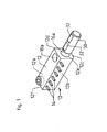
- a first embodiment of a manifold block 10 which has a base body 12 with four longitudinal sides 12a, 12b, 12c, 12d and two opposite end faces 12e, 12f.
- a plurality of longitudinally spaced apart connection elements 14 are arranged, which are at least partially, in this embodiment over the entire longitudinal direction, cuboid with four longitudinal sides 14a, 14b, 14c, 14d and two opposite end faces 14e, 14f formed ,
- the connecting elements 14 are advantageously arranged in one piece on the main body 12, in particular with its end face 14e.
- the longitudinal direction of the connecting elements 14 extends substantially perpendicular to the longitudinal side of the main body 12.
- the end faces 12e, 12f of the main body 12 each have a height hS and a width bS
- the end faces 14e, 14f of the connecting elements 14 each have a height hA and a width bA (cf. Figures 2 and 3 ).
- the height hS of the end faces 12e, 12f of the main body 12 is greater than the height hA of the end faces 14e, 14f of the connection elements 14.
- the widths bS of the end faces 12e, 12f of the base body 12 are greater than the widths bA of the end faces 14e, 14f of the connection elements 14.
- the area of one of the end faces 14e, 14f of the main body 12 is several times greater than the area of one of the end faces 14e, 14f of one of the connecting elements 14, preferably by a factor of at least 10.
- the end faces 12e, 12f and 14e, 14f formed approximately square.
- the height hA and the width bA of the end faces 14e, 14f of the connection elements 14 may each be 2 mm, while the height hS and the width bB of the end faces 12e, 12f of the base body 12 are each about 20 mm.
- the main body 12 is made of a conductive material, such as aluminum, brass or copper and may have a coating containing, for example, tin, zinc and / or nickel.
- the main body 12, in particular including the connecting elements 14, is for example milled, stamped, sprayed or cast, wherein the casting method is particularly preferred.
- a respective blind opening 16a, 16b is arranged in at least one of the end faces 14e, 14f (see embodiment in FIG Figures 21 and 22 ).
- a supply cable directly or a connection element of a supply cable can be introduced in the blind openings 16a, 16b.
- the blind openings 16a, 16b also serve to connect two distributor blocks 10.
- a through hole 18a, 18b is arranged up to the blind opening 16a, 16b, which in particular has an internal thread into which a clamping screw 20a, 20b can be screwed.
- a clamping screw 10a, 20b instead of a clamping screw 10a, 20b, a latching mechanism for fastening an electrically conductive element introduced into the blind opening 16a, 16b in the blind opening 16a, 16b or another fastening means may also be provided.
- a longitudinal connector 30, which is essentially formed as a cylindrical element, can be inserted at one end into the blind opening 16a (cf. FIG. 2 ) and in the blind opening 16a are fixed by means of the screwed into the through hole 18a clamping screw 20a (see. FIG. 3 ).
- the longitudinal connector 30 on its outer surface on a flat contact surface 32 on which the clamping screw 20a is applied, wherein the flat configuration of the contact surface 32 has a larger contact area between the longitudinal connector 30 and the clamping screw 20a is made possible.
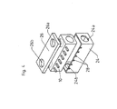
- the distribution block 10 can be arranged in an insulating housing 22.
- the housing 22 has a bottom part 24 and a cover part 26, which surround the distributor block 10.
- the base part 24 can have a plurality of slots 28, starting from a peripheral edge, in which, when the distributor block 10 is inserted into the bottom part 24, the connection elements 14 are guided and protrude outwardly from the inside of the housing.
- the bottom part 24 may further each have an opening 24a, 24b in its end faces, which are aligned with the blind openings 16a, 16b when the distributor block 10 is inserted into the bottom part 24, so that the blind openings 16a, 16b continue to be present even when the distributor block 10 is inserted into the housing 22 are accessible.
- two openings 26a, 26b are arranged in the cover part 26, which are aligned with the through holes 18a, 18b in the distribution block 10 inserted in the housing 22, so that the through holes 18a, 18b are accessible even when the distribution block 10 is inserted into the housing 22 ,
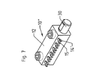
- FIG. 7 shows an alternative embodiment of a distribution block 10 ", which differs from the in FIG. 1 illustrated manifold block 10 only in the embodiment of the connection elements 14 'differs.
- the connection elements 14 ' are only partially formed cuboid, wherein on the free end face of the cuboid, a fork-shaped element 15 is arranged, which allows alternative connection types.
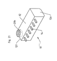
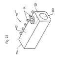
- FIG. 21 and 22 shows an alternative embodiment of a manifold block 10 "', which differs from the in FIG. 1 only differs in that a blind opening 16a, 16b is not provided in both end faces 12e, 12f, but only in the one end face 12f a blind opening 16b is arranged, while the other end face 12e is formed in particular closed.
- FIGS. 8 to 11 show the connection of two manifold blocks 10, 10 'by means of the longitudinal connector 30 to a manifold block assembly.
- the distributor block 10 ' is configured identically to the distributor block 10.
- the longitudinal connector 30 is pushed with its one end into the blind opening 16a of the end face 12e of the distributor block 10, while the other end of the longitudinal connector 30 is inserted into the blind opening 16b of the end face 12e the distributor block 10 facing end face 12f of the manifold block 10 'is inserted and the two manifold blocks 10, 10' are pushed together until the end face 12e of the manifold block 10 on the end face 12f of the manifold block 10 'is applied (see. FIG. 9 ).
- the longitudinal connector 30 is fixed by means of the clamping screw 20a in the distributor block 10 and by means of the clamping screw 20b in the distributor block 10 '(cf.
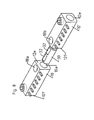
- FIGS. 12 to 15 an alternative embodiment of a manifold block assembly is shown with a parallel arrangement of the two manifold blocks 10, 10 ', wherein the two manifold blocks 10, 10' are interconnected by means of a cross connector 34 as described below.
- the distributor blocks 10, 10 ' are arranged in such a way that the longitudinal sides 12d of the base bodies 12 of the two distributor blocks 10, 10' lying opposite the connecting elements 14 abut one another.
- the two blind openings 16a, 16b of the distributor blocks 10, 10 ' lie in one plane.
- the cross connector 34 is approximately U-shaped and has two cylindrical sections 35, which are aligned with their longitudinal axis substantially parallel to each other and which in the blind opening 16b of the manifold block 10 and the blind opening 16a of the manifold block 10 'can be inserted (see. FIG. 13 ).
- the cross connector 34 is then fixed by means of the two clamping screws 20a, 20b in the manifold blocks 10, 10 '(see. Figures 14 and 15 ). Since the two distribution blocks 10, 10 'abut each other without electrical insulation, it is possible, the identical current to more connection elements 14, wherein the connection elements 14 are aligned in two different directions. Due to the cross-sectional increase in particular larger currents can be distributed.
- FIGS. 16 to 20 a further embodiment of a manifold block arrangement is shown, which differs from the in the FIGS. 12 to 15 illustrated manifold block arrangement differs only by the configuration of the cross connector 34.
- the manifold block assembly according to the FIGS. 16 to 20 has a cross connector 34 ', on which two additional connection openings 38, which are formed as blind openings, are arranged, which are arranged in particular in the cylindrical portions 35 opposite surface of the cross-connecting element of the cross connector 34.
- connection openings 38 each have a through hole 39, in which a clamping screw 40 for fixing a inserted into the connection opening 38 connecting cable or other longitudinal connector 30 or cross connector 34, 34' can be screwed.
- a clamping screw 40 instead of the clamping screw 40 and alternative fastening means such as a latching mechanism can be provided.
- the distributor blocks 10, 10 ', 10 ", 10''' and distribution block arrangements constructed therefrom can be used in particular in solar technology.
- the parallel aligned manifold blocks 10, 10 'as for example in the in the FIGS. 12 to 15 illustrated distributor block arrangement or in the in the FIGS. 16 to 20 isolate shown manifold block assembly, either in total or against each other.
- the manifold block assemblies can each be completely arranged in a larger housing. It is also possible to isolate the manifold blocks from each other either by arranging the manifold blocks 10, 10 'in a respective housing 22, as shown in FIG FIGS. 4 to 6 described, or by arrangement in a larger housing, wherein between the manifold blocks 10, 10 'an insulating partition wall is arranged to achieve.
Landscapes
- Connector Housings Or Holding Contact Members (AREA)
- Branch Pipes, Bends, And The Like (AREA)
- Valve Housings (AREA)
Abstract
Die Erfindung betrifft einen Verteilerblock (10, 10', 10", 10 ''' ) mit einem etwa quaderförmigen Grundkörper (12) mit vier Längsseiten (12a, 12b, 12c, 12d) und zwei Stirnseiten (12e, 12f), wobei der Grundkörper (12) aus einem leitfähigen Material gefertigt ist und an mindestens einer der Längsseiten (12b) mehrere Anschlusselemente (14, 14') angeordnet sind, wobei in wenigstens einer der Stirnflächen (12e, 12f) des Grundkörpers (12) eine Sacköffnung (16a, 16b) angeordnet ist und Befestigungsmittel zum Befestigen eines in die Sacköffnung eingeführten elektrisch leitenden Elements vorhanden sind.
Description
- Die Erfindung betrifft einen Verteilerblock, mittels welchem elektrischer Strom an verschiedene Anschlusskomponenten verteilt werden kann.
- Bekannt sind Verteilerblöcke mit einem Grundkörper und daran angeordneten Anschlusselementen, welche aus einer Platte ausgestanzt werden, wobei die Anschlusselemente gegebenenfalls anschließend nachbearbeitet, insbesondere gebogen werden müssen.
- Die
EP 1 930 986 A1 offenbart einen Verteilerblock mit einem Grundkörper und daran angeordneten Anschlusselementen, welcher einstückig in Form einer Platte mit daran angeordneten Anschlusselementen gegossen wird, welche anschließend gegebenenfalls ebenfalls in einem Nachbearbeitungsschritt abgebogen werden. - Nachteilig bei den bekannten Verteilerblöcken ist, dass diese kaum flexibel einsetzbar sind und insbesondere für variierende, insbesondere hohe, Ströme wenig geeignet sind.
- Die Aufgabe der Erfindung besteht darin, einen Verteilerblock bereitzustellen, welcher vielfältige Einsatzmöglichkeiten bietet.
- Die Aufgabe der Erfindung wird gelöst durch einen Verteilerblock mit den Merkmalen des Patentanspruchs 1.
- Vorteilhafte Ausgestaltungen und Weiterbildungen der Erfindung sind in den abhängigen Ansprüchen angegeben.
- Der erfindungsgemäße Verteilerblock weist einen insbesondere quaderförmigen Grundkörper mit vier Längsseiten und zwei Stirnseiten auf, wobei der Grundkörper aus einem leitfähigen Material gefertigt ist und an mindestens einer der Längsseiten mehrere Anschlusselemente angeordnet sind, wobei in wenigstens einer der Stirnflächen des Grundkörpers eine Sacköffnung angeordnet ist und Befestigungsmittel zum Befestigen eines in die Sacköffnung eingeführten elektrisch leitenden Elements vorhanden sind. Dabei sind als elektrisch leitende Elemente nicht nur elektrische Leiter wie Kabel anzusehen, sondern beispielsweise auch Verbindungselemente, mittels welcher zwei oder mehrere erfindungsgemäße Verteilerblöcke miteinander verbunden werden können. Über die Sacköffnung wird somit insbesondere ein Anschluss beispielsweise eines Versorgungskabels oder auch die Möglichkeit zur Verbindung zweier erfindungsgemäßer Ventilblöcke in konstruktiv einfacher Art und Weise ermöglicht. Insbesondere wird durch die Verwendung der Sacköffnung die Möglichkeit geschaffen, sowohl die Einspeisevorrichtung als auch die Abgänge aus einem Material, insbesondere aus einem Stück zu fertigen.
- Gemäß einer bevorzugten Ausführungsform der Erfindung sind die Befestigungsmittel als Klemmschraube ausgebildet, welche in ein Innengewinde eindrehbar ist, welches in einer ausgehend von einer der Längsseiten des Grundkörpers angeordneten Durchgangsbohrung zu der Sacköffnung angeordnet ist. Eine derartige Ausführung der Befestigungsmittel ist besonders einfach und kostengünstig herzustellen.
- Vorteilhafterweise sind die Befestigungsmittel als wenigstens ein Rastelement ausgebildet, welches in der Sacköffnung angeordnet ist. Eine derartige Ausführung der Befestigungsmittel ist besonders platzsparend.
- Vorzugsweise sind die Anschlusselemente mit jeweils einer der Stirnflächen der Anschlusselemente einstückig an der einen Längsseite des Grundkörpers angeordnet, wodurch sich eine ausreichende Länge der Anschlusselemente für ein einfaches Anschließen an den Anschlusselementen ergibt.
- Gemäß einer bevorzugten Ausführungsform der Erfindung sind die Anschlusselemente zumindest abschnittsweise quaderförmig mit vier Längsseiten und zwei Stirnseiten ausgebildet und sowohl die Höhe der Stirnseite des Grundkörpers ist größer als die Höhe der Stirnseite des Anschlusselements als auch die Breite der Stirnseite des Grundkörpers ist größer als die Breite der Stirnseite des Anschlusselements. Dadurch ergibt sich ein Verteilerblock mit einem Grundkörper, der eine wesentlich größere Querschnittsfläche aufweist als die Anschlusselemente, sodass mit dem Verteilerblock auch große Ströme problemlos verteilt werden können.
- Gemäß einer bevorzugten Ausführungsform der Erfindung ist die Fläche der Stirnseite des Grundkörpers mindestens um einen Faktor 10 größer als die Fläche der Stirnseite eines der Anschlusselemente, was die Verteilung von hohen Strömen begünstigt.
- Eine bevorzugte Ausführungsform der Erfindung sieht vor, dass der Verteilerblock in einem isolierenden Gehäuse angeordnet ist, um zu vermeiden, dass ein Benutzer mit stromführenden Elementen in Kontakt kommt.
- Gemäß einer besonders bevorzugten Ausführungsform der Erfindung ist das Gehäuse zweiteilig mit einem Bodenteil und einem Deckelteil ausgebildet, wobei in dem Bodenteil ausgehend von einer Randkante Schlitze zum Einführen der Anschlusselemente angeordnet sind. Die zweiteilige Ausgestaltung ermöglicht ein einfaches Einsetzen des Verteilerblocks in das Gehäuse. Durch die Schlitze in einem der Gehäuseteile wird eine zuverlässige Isolierung bei einem einfachen Einführen in das Gehäuseteil ermöglicht.
- Vorteilhafterweise sind in dem Bodenteil Öffnungen angeordnet, welche mit den vorhandenen Sacköffnungen fluchten und/oder in dem Deckelteil der Öffnungen angeordnet, welche mit den vorhandenen Durchgangsbohrungen fluchten, um auch bei einem isolierten Verteilerblock sowohl ein Einführen der Versorgungskabel als auch ein Fixieren der Versorgungskabel zu ermöglichen.
- Eine vorteilhafte Ausführungsform der Erfindung sieht vor, dass der Verteilerblock aus Aluminium, Messing oder Kupfer gefertigt ist, da diese Materialien einfach zu verarbeiten sind und eine hohe Leitfähigkeit aufweisen.
- In einer Ausführungsform der Erfindung weist der Verteilerblock zur Verbesserung der Korrosionsbeständigkeit eine Beschichtung auf, welche Zinn, Zink und/oder Nickel enthält.
- Gemäß einer besonders bevorzugten Ausführungsform der Erfindung ist der Verteilerblock gefräst, gestanzt, gespritzt oder gegossen, wodurch auf einfache Art und Weise eine einstückige Fertigung des Verteilerblocks ermöglicht wird, wobei besonders bevorzugt der Verteilerblock gegossen ist, um ein kostengünstiges Herstellungsverfahren zu ermöglichen, welches kaum eine Nachbearbeitung erfordert.
- Vorteilhafterweise sind die Stirnseiten des Grundkörpers und/oder die Stirnseiten der Anschlusselemente in etwa quadratisch, wodurch sich bei kompaktem Aufbau eine möglichst große Querschnittsfläche ergibt, welche das Verteilen auch von hohen Strömen begünstigt.
- Eine erfindungsgemäße Verteilerblockanordnung weist einen ersten erfindungsgemäßen Verteilerblock und einen zweiten erfindungsgemäßen Verteilerblock auf, welche entweder in Längsrichtung zueinander fluchten oder parallel zueinander angeordnet sind, wodurch sich vielfältige Möglichkeiten zur Kombination der erfindungsgemäßen Verteilerblöcke ergeben, welche eine flexible Bereitstellung einer Verteilerblockanordnung ermöglichen. Die in Längsrichtung zueinander fluchtend angeordneten Verteilerblöcke ermöglichen auf einfache Art und Weise das Bereitstellen einer Verteilerblockanordnung mit beliebiger Zahl von Anschlusselementen. Die parallele Anordnung zweier Verteilerblöcke ermöglicht entweder das Verteilen von zwei verschiedenen Strömen oder das Bereitstellen eines größeren Querschnitts zur Verteilung von höheren Strömen.
- Vorzugsweise erfolgt die Verbindung der beiden Verteilerblöcke bei Anordnung in Längsrichtung zueinander fluchtend mittels eines in die in einander zugewandten Stirnseiten angeordneten Sacköffnungen eingesetzten Längsverbinders und die Verbindung der beiden Verteilerblöcke bei Anordnung parallel zueinander mittels eines in die in den in einer Ebene liegenden Stirnseiten angeordneten Sacköffnungen eingesetzten U-förmigen Querverbinders. Eine derartige Verbindung ist ohne großen Aufwand kostengünstig zu realisieren.
- In einer vorteilhaften Ausführungsform der Erfindung weist der Querverbinder wenigstens eine, vorzugsweise zwei, Sacköffnungen auf, wobei Befestigungsmittel zum Befestigen eines in die Sacköffnung eingeführten elektrisch leitenden Elements vorhanden sind. Dadurch wird die Flexibilität der Verbindungsanordnung weiter erhöht.
- Vorzugsweise sind der erste und der zweite Verteilerblock in einem gemeinsamen isolierenden Gehäuse angeordnet, wobei vorzugsweise, falls eine Isolierung der beiden Verteilerblöcke gegeneinander gewünscht ist, zwischen den beiden Verteilerblöcken eine isolierende Trennwand angeordnet ist.
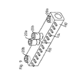
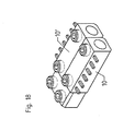
- Die Erfindung wird anhand der nachfolgenden Figuren ausführlich erläutert. Es zeigt
- Figur 1
- eine perspektivische Ansicht eines Ausführungsbeispiels eines erfindungsgemäßen Verteilerblocks und eines Längsverbinders,
- Figur 2
- den Verteilerblock gemäß
Figur 1 mit eingesetztem Längsverbinder, - Figur 3
- den Verteilerblock gemäß
Figur 1 mit mittels einer Klemmschraube fixiertem Längsverbinder, - Figur 4
- den Verteilerblock gemäß
Figur 1 mit einem isolierenden Gehäuse in Explosionsdarstellung, - Figur 5
- den Verteilerblock gemäß
Figur 4 im zusammengesetzten Zustand, - Figur 6
- einen Querschnitt durch den Verteilerblock gemäß
Figur 5 , - Figur 7
- eine perspektivische Ansicht eines weiteren Ausführungsbeispiels eines erfindungsgemäßen Verteilerblocks mit eingesetztem Längsverbinder,
- Figur 8
- eine perspektivische Ansicht der Komponenten einer Verteilerblockanordnung mit zwei Verteilerblöcken gemäß
Figur 1 und einem Längsverbinder, - Figur 9
- die Verteilerblockanordnung gemäß
Figur 8 im aneinander gelegten Zustand der beiden Verteilerblöcke, - Figur 10
- die Verteilerblockanordnung gemäß
Figur 9 mit eingedrehten Klemmschrauben, - Figur 11
- eine teilweise geschnittene Ansicht der Verteilerblockanordnung gemäß
Figur 10 , - Figur 12
- eine perspektivische Ansicht der Komponenten einer Verteilerblockanordnung mit zwei Verteilerblöcken gemäß
Figur 1 und einem Querverbinder, - Figur 13
- die Verteilerblockanordnung gemäß
Figur 12 im aneinandergelegten Zustand der beiden Verteilerblöcke mit eingeschobenem Querverbinder, - Figur 14
- die Verteilerblockanordnung gemäß
Figur 13 mit eingedrehten Klemmschrauben, - Figur 15
- eine teilweise geschnittene Ansicht der Verteilerblockanordnung gemäß
Figur 14 , - Figur 16
- eine perspektivische Ansicht der Komponenten einer Verteilerblockanordnung mit zwei Verteilerblöcken gemäß
Figur 1 und einer alternativen Ausführungsform eines Querverbinders, - Figur 17
- die Verteilerblockanordnung gemäß
Figur 16 im aneinandergelegten Zustand der beiden Verteilerblöcke mit eingeschobenem Querverbinder, - Figur 18
- die Verteilerblockanordnung gemäß
Figur 17 mit eingedrehten Klemmschrauben, - Figur 19
- eine teilweise geschnittene Ansicht der Verteilerblockanordnung gemäß
Figur 18 , - Figur 20
- eine weitere perspektivische Ansicht der Verteilerblockanordnung gemäß
Figur 18 , - Figur 21
- eine perspektivische Ansicht eines weiteren Ausführungsbeispiels eines erfindungsgemäßen Verteilerblocks und
- Figur 22
- eine weitere perspektivische Ansicht des Ausführungsbeispiels eines erfindungsgemäßen Verteilerblocks gemäß
Figur 21 . - In den
Figuren 1 bis 22 bezeichnen gleiche Bezugsziffern gleiche Teile. Zur besseren Übersicht sind nicht sämtliche Bezugsziffern in sämtlichen Figuren dargestellt. - In den
Figuren 1 bis 3 ist ein erstes Ausführungsbeispiel eines Verteilerblocks 10 dargestellt, welcher einen Grundkörper 12 mit vier Längsseiten 12a, 12b, 12c, 12d und zwei gegenüberliegenden Stirnseiten 12e, 12f aufweist. An dem Grundkörper 12 sind an der Längsseite 12b mehrere in Längsrichtung gegeneinander beabstandete Anschlusselemente 14 angeordnet, welche zumindest abschnittsweise, in diesem Ausführungsbeispiel über die gesamte Längsrichtung, quaderförmig mit vier Längsseiten 14a, 14b, 14c, 14d und zwei gegenüberliegenden Stirnseiten 14e, 14f ausgebildet sind. Dabei sind die Anschlusselemente 14 vorteilhafterweise einstückig an dem Grundkörper 12 angeordnet, insbesondere mit ihrer Stirnseite 14e. Dabei verläuft insbesondere die Längsrichtung der Anschlusselemente 14 im Wesentlichen senkrecht zur Längsseite des Grundkörpers 12. - Die Stirnseiten 12e, 12f der Grundkörper 12 weisen jeweils eine Höhe hS und eine Breite bS auf, die Stirnseiten 14e, 14f der Anschlusselemente 14 weisen jeweils eine Höhe hA und eine Breite bA auf (vgl.
Figuren 2 und3 ). Die Höhe hS der Stirnseiten 12e, 12f des Grundkörpers 12 ist größer als die Höhe hA der Stirnseiten 14e, 14f der Anschlusselemente 14. Die Breiten bS der Stirnseiten 12e, 12f der Grundkörper 12 sind größer als die Breiten bA der Stirnseiten 14e, 14f der Anschlusselemente 14. Besonders bevorzugt ist die Fläche einer der Stirnseiten 14e, 14f des Grundkörpers 12 um ein Mehrfaches größer als die Fläche einer der Stirnseiten 14e, 14f eines der Anschlusselemente 14, vorzugsweise um einen Faktor von mindestens 10. Vorzugsweise sind die Stirnseiten 12e, 12f und 14e, 14f etwa quadratisch ausgebildet. Beispielsweise kann die Höhe hA und die Breite bA der Stirnseiten 14e, 14f der Anschlusselemente 14 jeweils 2 mm betragen, während die Höhe hS und die Breite bB der Stirnseiten 12e, 12f des Grundkörpers 12 jeweils etwa 20 mm beträgt. - Der Grundkörper 12 ist aus einem leitfähigen Material, beispielsweise Aluminium, Messing oder Kupfer gefertigt und kann eine Beschichtung aufweisen, welche beispielsweise Zinn, Zink und/oder Nickel enthält. Der Grundkörper 12, insbesondere einschließlich der Anschlusselemente 14, wird beispielsweise gefräst, gestanzt, gespritzt oder gegossen, wobei das Gussverfahren besonders bevorzugt ist.
- In wenigstens einer der Stirnseiten 14e, 14f (vgl. Ausführungsbeispiel in
Figuren 21 und22 ), vorzugsweise in beiden Stirnseiten 14e, 14f, ist jeweils eine Sacköffnung 16a, 16b angeordnet. In die Sacköffnungen 16a, 16b kann beispielsweise ein Versorgungskabel direkt oder ein Anschlusselement eines Versorgungskabels eingeführt werden. Wie nachfolgend detaillierter beschrieben, dienen die Sacköffnungen 16a, 16b auch zur Verbindung zweier Verteilerblöcke 10. - Ausgehend von der Längsseite 12a des Grundkörpers 12 ist in einer Ausführungsform eine Durchgangsbohrung 18a, 18b bis zur Sacköffnung 16a, 16b angeordnet, welche insbesondere ein Innengewinde aufweist, in welches eine Klemmschraube 20a, 20b eindrehbar ist. Alternativ kann statt einer Klemmschraube 10a, 20b auch ein Rastmechanismus zum Befestigen eines in die Sacköffnung 16a, 16b eingeführten elektrisch leitenden Elements in der Sacköffnung 16a, 16b oder ein sonstiges Befestigungsmittel vorgesehen sein.
- Wie in den
Figuren 1 bis 3 dargestellt, kann ein Längsverbinder 30, welcher im Wesentlichen als zylindrisches Element ausgebildet ist, einendseitig in die Sacköffnung 16a eingeführt werden (vgl.Figur 2 ) und in der Sacköffnung 16a mittels der in die Durchgangsbohrung 18a eingedrehten Klemmschraube 20a fixiert werden (vgl.Figur 3 ). Um einen guten Kontakt zwischen der Klemmschraube 20a und dem Längsverbinder 30 zu gewährleisten und ein Verdrehen des Längsverbinders 30 zu verhindern, weist der Längsverbinder 30 auf seiner Außenfläche eine ebene Kontaktfläche 32 auf, an welcher die Klemmschraube 20a anliegt, wobei durch die ebene Ausgestaltung der Kontaktfläche 32 eine größere Kontaktfläche zwischen dem Längsverbinder 30 und der Klemmschraube 20a ermöglicht wird. - Wie anhand der
Figuren 4 bis 6 beschrieben, kann der Verteilerblock 10 in einem isolierenden Gehäuse 22 angeordnet werden. Das Gehäuse 22 weist ein Bodenteil 24 und ein Deckelteil 26 auf, welche den Verteilerblock 10 umgeben. Das Bodenteil 24 kann ausgehend von einer Randkante mehrere Schlitze 28 aufweisen, in welchen bei Einsetzen des Verteilerblocks 10 in das Bodenteil 24 die Anschlusselemente 14 geführt werden und aus dem Gehäuseinneren nach außen hervorragen. - Das Bodenteil 24 kann weiterhin in seinen Stirnseiten jeweils eine Öffnung 24a, 24b aufweisen, welche beim in das Bodenteil 24 eingesetztem Verteilerblock 10 mit den Sacköffnungen 16a, 16b fluchten, sodass auch bei Einsetzen des Verteilerblocks 10 in das Gehäuse 22 die Sacköffnungen 16a, 16b weiterhin zugänglich sind. Ebenso sind gemäß einer Ausführungsform in dem Deckelteil 26 zwei Öffnungen 26a, 26b angeordnet, welche beim in dem Gehäuse 22 eingesetztem Verteilerblock 10 mit den Durchgangsbohrungen 18a, 18b fluchten, sodass die Durchgangsbohrungen 18a, 18b auch bei in das Gehäuse 22 eingesetztem Verteilerblock 10 zugänglich sind.
-
Figur 7 zeigt eine alternative Ausgestaltung eines Verteilerblocks 10", welcher sich von dem inFigur 1 dargestellten Verteilerblock 10 lediglich in der Ausgestaltung der Anschlusselemente 14' unterscheidet. Die Anschlusselemente 14' sind lediglich abschnittsweise quaderförmig ausgebildet, wobei an der freien Stirnseite des Quaders ein gabelförmiges Element 15 angeordnet ist, welches alternative Anschlussarten ermöglicht. - Die
Figuren 21 und22 zeigt eine alternative Ausgestaltung eines Verteilerblocks 10"', welcher sich von dem inFigur 1 dargestellten Verteilerblock 10 lediglich darin unterscheidet, dass nicht in beiden Stirnseiten 12e, 12f jeweils eine Sacköffnung 16a, 16b vorgesehen ist, sondern nur in der einen Stirnseite 12f eine Sacköffnung 16b angeordnet ist, während die andere Stirnseite 12e insbesondere geschlossen ausgebildet ist. - Die
Figuren 8 bis 11 zeigen die Verbindung zweier Verteilerblöcke 10, 10' mittels des Längsverbinders 30 zu einer Verteilerblockanordnung. Der Verteilerblock 10' ist dabei identisch zu dem Verteilerblock 10 ausgestaltet. Dabei können als Verteilerblöcke 10, 10' selbstverständlich auch die alternativen Ausgestaltungen der Verteilerblöcke 10" oder 10''' verwendet werden und beliebige Kombinationen von Verteilerblöcken 10, 10" und 10''' gebildet werden. - Um die beiden Verteilerblöcke 10, 10' in Längsrichtung miteinander fluchtend zu verbinden, wird der Längsverbinder 30 mit seinem einen Ende in die Sacköffnung 16a der Stirnseite 12e des Verteilerblocks 10 geschoben, während das andere Ende des Längsverbinders 30 in die Sacköffnung 16b der der Stirnseite 12e des Verteilerblocks 10 zugewandten Stirnseite 12f des Verteilerblocks 10' eingeschoben wird und die beiden Verteilerblöcke 10, 10' soweit aneinander geschoben werden, bis die Stirnseite 12e des Verteilerblocks 10 an der Stirnseite 12f des Verteilerblocks 10' anliegt (vgl.
Figur 9 ). Der Längsverbinder 30 wird mittels der Klemmschraube 20a in dem Verteilerblock 10 und mittels der Klemmschraube 20b in dem Verteilerblock 10' fixiert (vgl.Figuren 10 und11 ). Damit beide Klemmschrauben 20a, 20b einen guten Kontakt zu dem Längsverbinder 30 haben, weist der Längsverbinder in Längsrichtung gegeneinander beabstandet zwei Kontaktflächen 32, welche insbesondere als ebene Flächen ausgebildet sind, auf. Durch eine derartige Verbindung wird eine Verteilerblockanordnung mit zwei Verteilerblöcken 10, 10' erreicht, welche eine größere Länge aufweist. Auf diese Art und Weise können beliebig viele Verteilerblöcke 10 miteinander verbunden werden, um beliebige Längen einer Verteilerblockanordnung zu ermöglichen. - In den
Figuren 12 bis 15 ist eine alternative Ausgestaltung einer Verteilerblockanordnung mit einer parallelen Anordnung der beiden Verteilerblöcke 10, 10' dargestellt, wobei die beiden Verteilerblöcke 10, 10' wie nachfolgend beschrieben mittels eines Querverbinders 34 miteinander verbunden werden. Die Verteilerblöcke 10, 10' sind derart angeordnet, dass die den Anschlusselementen 14 gegenüber liegenden Längsseiten 12d der Grundkörper 12 der beiden Verteilerblöcke 10, 10' aneinander liegen. Dadurch liegen jeweils die beiden Sacköffnungen 16a, 16b der Verteilerblöcke 10, 10' in einer Ebene. Der Querverbinder 34 ist etwa U-förmig ausgebildet und weist zwei zylindrische Abschnitte 35 auf, welche mit ihrer Längsachse im Wesentlichen parallel zueinander ausgerichtet sind und welche in die Sacköffnung 16b des Verteilerblocks 10 und die Sacköffnung 16a des Verteilerblocks 10' eingeführt werden können (vgl.Figur 13 ). Der Querverbinder 34 wird anschließend mittels der beiden Klemmschrauben 20a, 20b in den Verteilerblöcken 10, 10' fixiert (vgl.Figuren 14 und15 ). Da die beiden Verteilerblöcke 10, 10' ohne elektrische Isolierung aneinander anliegen, ist es möglich, den identischen Strom an mehr Anschlusselemente 14 zu verteilen, wobei die Anschlusselemente 14 in zwei verschiedene Richtungen ausgerichtet sind. Auf Grund der Querschnittserhöhung können insbesondere größere Ströme verteilt werden. - In den
Figuren 16 bis 20 ist ein weiteres Ausführungsbeispiel einer Verteilerblockanordnung dargestellt, welche sich von der in denFiguren 12 bis 15 dargestellten Verteilerblockanordnung lediglich durch die Ausgestaltung des Querverbinders 34 unterscheidet. Die Verteilerblockanordnung gemäß denFiguren 16 bis 20 weist einen Querverbinder 34' auf, an welchem zwei zusätzliche Anschlussöffnungen 38, welches als Sacköffnungen ausgebildet sind, angeordnet sind, die insbesondere in der den zylindrischen Abschnitten 35 gegenüberliegenden Fläche des querverbindenden Elements des Querverbinders 34 angeordnet sind. Ausgehend von einer Seitenfläche des Querverbinders 34' ist bis zu den Anschlussöffnungen 38 jeweils eine Durchgangsbohrung 39 angeordnet, in welche eine Klemmschraube 40 zur Fixierung eines in die Anschlussöffnung 38 eingeführten Anschlusskabels oder weiteren Längsverbinders 30 oder Querverbinders 34, 34' eingedreht werden kann. Statt der Klemmschraube 40 können auch alternative Befestigungsmittel wie beispielsweise ein Rastmechanismus vorgesehen werden. - Auf diese Weise ergeben sich vielfältige Kombinationsmöglichkeiten zweier oder mehrerer Verteilerblöcke 10, 10', 10", 10''', um einen flexiblen Aufbau einer Verteilerblockanordnung zu ermöglichen.
- Die Verteilerblöcke 10, 10', 10", 10''' und daraus aufgebaute Verteilerblockanordnungen können insbesondere in der Solartechnik eingesetzt werden.
- Selbstverständlich ist es möglich, auch die parallel zueinander ausgerichteten Verteilerblöcke 10, 10' wie beispielsweise in der in den
Figuren 12 bis 15 dargestellten Verteilerblockanordnung oder in der der in denFiguren 16 bis 20 dargestellten Verteilerblockanordnung zu isolieren, entweder insgesamt oder auch gegeneinander. Dabei können die Verteilerblockanordnungen jeweils vollständig in einem größeren Gehäuse angeordnet werden. Es ist auch möglich, eine Isolierung der Verteilerblöcke gegeneinander entweder durch Anordnung der Verteilerblöcke 10, 10' in jeweils einem Gehäuse 22, wie anhand derFiguren 4 bis 6 beschrieben, oder durch Anordnung in einem größeren Gehäuse, wobei zwischen den Verteilerblöcken 10, 10' eine isolierende Trennwand angeordnet ist, zu erreichen. -
- 10, 10', 10", 10'''
- Verteilerblock
- 12
- Grundkörper
- 12a, 12b, 12c, 12d
- Längsseite
- 12e, 12f
- Stirnseite
- 14, 14'
- Anschlusselement
- 14a, 14b, 14c, 14d
- Längsseite
- 14e, 14f
- Stirnseite
- 15
- Gabelförmiges Element
- 16a, 16b
- Sacköffnung
- 18a, 18b
- Durchgangsbohrung
- 20a, 20b
- Klemmschraube
- 22
- Gehäuse
- 24
- Bodenteil
- 24a, 24b
- Öffnung
- 26
- Deckelteil
- 26a, 26b
- Öffnung
- 28
- Schlitz
- 30
- Längsverbinder
- 32
- Kontaktfläche
- 34, 34'
- Querverbinder
- 35
- Zylindrischer Abschnitt
- 36
- Auflagefläche
- 38
- Anschlussöffnung
- 39
- Durchgangsbohrung
- 40
- Klemmschraube
- hS
- Höhe
- bS
- Breite
- hA
- Höhe
- bA
- Breite
Claims (17)
- Verteilerblock (10, 10', 10", 10"') mit einem Grundkörper (12) mit vier Längsseiten (12a, 12b, 12c, 12d) und zwei Stirnseiten (12e, 12f), wobei der Grundkörper (12) aus einem leitfähigen Material gefertigt ist und an mindestens einer der Längsseiten (12b) mehrere Anschlusselemente (14, 14') angeordnet sind, wobei in wenigstens einer der Stirnflächen (12e, 12f) des Grundkörpers (12) eine Sacköffnung (16a, 16b) angeordnet ist und Befestigungsmittel zum Befestigen eines in die Sacköffnung eingeführten elektrisch leitenden Elements vorhanden sind.
- Verteilerblock nach Anspruch 1,
dadurch gekennzeichnet, dass die Befestigungsmittel als Klemmschraube (20a, 20b) ausgebildet sind, welche in ein Innengewinde eindrehbar ist, welches in einer ausgehend von einer der Längsseiten (12a) des Grundkörpers (12) angeordneten Durchgangsbohrung (18a, 18b) zu der Sacköffnung (16a, 16b) angeordnet ist. - Verteilerblock nach Anspruch 1,
dadurch gekennzeichnet, dass die Befestigungsmittel als wenigstens ein Rastelement ausgebildet sind, welches in der Sacköffnung angeordnet ist. - Verteilerblock nach einem der vorhergehenden Ansprüche,
dadurch gekennzeichnet, dass die Anschlusselemente (14, 14') mit jeweils einer der Stirnflächen (14e) der Anschlusselemente (14, 14') einstückig an einer der Längsseiten (12b) des Grundkörpers (12) angeordnet sind. - Verteilerblock nach einem der vorhergehenden Ansprüche,
dadurch gekennzeichnet, dass die Anschlusselemente (14, 14') zumindest abschnittsweise quaderförmig mit vier Längsseiten (14a, 14b, 14c, 14d) und zwei Stirnseiten (14e, 14f)ausgebildet sind und wobei sowohl die Höhe (hS) der Stirnseite (12e, 12f) des Grundkörpers (12) größer ist als die Höhe (hA) der Stirnseite (14e, 14f) des Anschlusselements (14, 14') als auch die Breite (bS) der Stirnseite (12e, 12f)des Grundkörpers (12) größer ist als die Breite (bA) der Stirnseite (14e, 14f)des Anschlusselements (14, 14'). - Verteilerblock nach einem der vorhergehenden Ansprüche,
dadurch gekennzeichnet, dass die Fläche der Stirnseite (12e, 12f) des Grundkörpers (12) um einen Faktor von mindestens 10 größer ist als die Fläche der Stirnseite (14e, 14f) eines der Anschlusselemente (14, 14'). - Verteilerblock nach einem der vorhergehenden Ansprüche,
dadurch gekennzeichnet, dass der Verteilerblock (10, 10', 10", 10"') in einem isolierenden Gehäuse (22) angeordnet ist. - Verteilerblock nach Anspruch 7,
dadurch gekennzeichnet, dass das Gehäuse (22) zweiteilig mit einem Bodenteil (24) und einem Deckelteil (26) ausgebildet ist, wobei in dem Bodenteil (24) ausgehend von einer Randkante Schlitze (28) zum Einführen der Anschlusselemente (14, 14') angeordnet sind. - Verteilerblock nach Anspruch 8,
dadurch gekennzeichnet, dass in dem Bodenteil (24) Öffnungen (24a, 24b) angeordnet sind, welche mit den vorhandenen Sacköffnungen (16a, 16b) fluchten und/oder dass in dem Deckelteil (26) Öffnungen (26a, 26b) angeordnet sind, welche mit den vorhandenen Durchgangsbohrungen (18a, 18b) fluchten. - Verteilerblock nach einem der vorhergehenden Ansprüche,
dadurch gekennzeichnet, dass der Verteilerblock (10, 10', 10", 10"') aus Aluminium, Messing oder Kupfer gefertigt ist. - Verteilerblock nach einem der vorhergehenden Ansprüche,
dadurch gekennzeichnet, dass der Verteilerblock (10, 10', 10", 10''') eine Beschichtung aufweist, welche Zinn, Zink und/oder Nickel enthält. - Verteilerblock nach einem der vorhergehenden Ansprüche,
dadurch gekennzeichnet, dass der Verteilerblock (10, 10', 10'', 10"') gefräst, gestanzt, gespritzt oder gegossen ist. - Verteilerblock nach einem der vorhergehenden Ansprüche,
dadurch gekennzeichnet, dass die Stirnseiten (12e, 12f) des Grundkörpers (12) und/oder die Stirnseiten (14e, 14f) der Anschlusselemente (14, 14') etwa quadratisch sind. - Verteilerblockanordnung,
dadurch gekennzeichnet, dass ein erster Verteilerblock (10) nach einem der vorhergehenden Ansprüche und ein zweiter Verteilerblock (10') nach einem der vorhergehenden Ansprüche entweder in Längsrichtung zueinander fluchtend oder parallel zueinander angeordnet sind. - Verteilerblockanordnung nach Anspruch 14,
dadurch gekennzeichnet, dass die Verbindung der beiden Verteilerblöcke (10, 10') bei Anordnung in Längsrichtung zueinander fluchtend mittels eines in die in einander zugewandten Stirnseiten (12e, 12f) angeordneten Sacköffnungen (16a, 16b) eingesetzten Längsverbinders (30) erfolgt oder dass die Verbindung der beiden Verteilerblöcke (10, 10') bei Anordnung parallel zueinander mittels eines in die in den in einer Ebene liegenden Stirnseiten (12a, 12b) angeordneten Sacköffnungen (16a, 16b) eingesetzten U-förmigen Querverbinders (34, 34') erfolgt. - Verteilerblockanordnung nach einem der Ansprüche 14 oder 15,
dadurch gekennzeichnet, dass der Querverbinder wenigstens eine, vorzugsweise zwei, Sacköffnungen aufweist und Befestigungsmittel zum Befestigen eines in die Sacköffnung eingeführten elektrisch leitenden Elements vorhanden sind. - Verteilerblockanordnung nach einem der Ansprüche 14 bis 16,
dadurch gekennzeichnet, dass der erste und der zweite Verteilerblock (10, 10') in einem gemeinsamen isolierenden Gehäuse angeordnet sind, wobei vorzugsweise zwischen den beiden Verteilerblöcken eine isolierende Trennwand angeordnet ist.
Applications Claiming Priority (1)
| Application Number | Priority Date | Filing Date | Title |
|---|---|---|---|
| DE102012108616.8A DE102012108616A1 (de) | 2012-09-14 | 2012-09-14 | Verteilerblock |
Publications (1)
| Publication Number | Publication Date |
|---|---|
| EP2709210A1 true EP2709210A1 (de) | 2014-03-19 |
Family
ID=48625840
Family Applications (1)
| Application Number | Title | Priority Date | Filing Date |
|---|---|---|---|
| EP13171560.9A Withdrawn EP2709210A1 (de) | 2012-09-14 | 2013-06-11 | Verteilerblock |
Country Status (3)
| Country | Link |
|---|---|
| US (1) | US8801475B2 (de) |
| EP (1) | EP2709210A1 (de) |
| DE (1) | DE102012108616A1 (de) |
Cited By (1)
| Publication number | Priority date | Publication date | Assignee | Title |
|---|---|---|---|---|
| CN107994389A (zh) * | 2017-12-06 | 2018-05-04 | 中山市凌智照明电器有限公司 | 一种组合式电源连接装置 |
Families Citing this family (3)
| Publication number | Priority date | Publication date | Assignee | Title |
|---|---|---|---|---|
| EP3369139B1 (de) * | 2015-10-27 | 2021-02-24 | SEW-Eurodrive GmbH & Co | Anschlusseinheit für ein elektrogerät, elektrogerätesystem und verfahren zur herstellung |
| US9553374B1 (en) * | 2015-11-19 | 2017-01-24 | Tyco Electronics Canada Ulc | Electrical connectors and connection assemblies and methods including the same |
| US10122098B2 (en) * | 2016-04-01 | 2018-11-06 | Varentec, Inc. | Transformer terminal coupler in close proximity to a distribution transformer for connecting at least one electrical device to one or more loads |
Citations (11)
| Publication number | Priority date | Publication date | Assignee | Title |
|---|---|---|---|---|
| GB830765A (en) * | 1958-02-28 | 1960-03-23 | Belling & Lee Ltd | Improvements in or relating to electrical contact elements |
| FR2757688A1 (fr) * | 1996-12-20 | 1998-06-26 | Mecelec Ind | Connecteur de raccordement electrique d'un cable a une barre |
| WO2002005389A1 (en) * | 2000-07-12 | 2002-01-17 | Landis + Gyr Ltd. | Improvements in or relating to terminals |
| US6368162B1 (en) * | 1999-08-03 | 2002-04-09 | Kerry L. Reetz | Temperature resistive electrical distribution block |
| DE20300617U1 (de) * | 2003-01-15 | 2003-03-20 | WECO Wester, Ebbinghaus GmbH & Co KG, 63452 Hanau | Elektrische Anschlussklemme |
| US20040067697A1 (en) * | 2002-10-02 | 2004-04-08 | Homac Manufacturing Company | Slip-fit connector compatible with different size transformer studs and related methods |
| US20060105637A1 (en) * | 2004-11-17 | 2006-05-18 | Excel Cell Electronic Co., Ltd. | Terminal-mounting seat |
| CA2531931A1 (en) * | 2005-12-29 | 2007-06-29 | Christopher E. Walton | Fast change transformer connector and adaptor |
| EP1930986A1 (de) | 2006-12-05 | 2008-06-11 | Auxel | Verfahren zur Herstellung von Überbrückungskämmen |
| US20090035987A1 (en) * | 2007-08-03 | 2009-02-05 | Btx Technologies, Inc. | Connector assembly |
| US7537467B1 (en) * | 2008-10-07 | 2009-05-26 | Arlington Industries, Inc. | Grounding terminal block assembly for multiple services |
Family Cites Families (38)
| Publication number | Priority date | Publication date | Assignee | Title |
|---|---|---|---|---|
| US3133779A (en) * | 1962-06-12 | 1964-05-19 | Square D Co | Neutral wire connector |
| US3577114A (en) * | 1969-12-12 | 1971-05-04 | Thomas & Betts Corp | Connecting device |
| US3794963A (en) * | 1972-04-24 | 1974-02-26 | Itt | Electrical connector |
| US4214806A (en) * | 1979-07-27 | 1980-07-29 | Kraft Russell H | Fast release connector |
| US4382651A (en) * | 1980-07-18 | 1983-05-10 | Homac Mfg. Company | Transformer bar connector |
| US4456326A (en) * | 1982-08-04 | 1984-06-26 | Sauber Charles J | Wall mountable cable terminal block |
| US4547627A (en) * | 1983-07-19 | 1985-10-15 | Homac Mfg. Company | Transformer bar connector and pedestal bar connector cover |
| US4513169A (en) * | 1983-07-19 | 1985-04-23 | Homac Mfg. Company | Transformer bar connector cover |
| US5199905A (en) * | 1992-03-09 | 1993-04-06 | Connector Manufacturing Co. | Lay-in pedestal connector bar and method |
| US5727314A (en) * | 1996-02-15 | 1998-03-17 | Erico International Corporation | Method of making an insulated set screw electrical connector |
| US5931708A (en) * | 1996-09-13 | 1999-08-03 | Hubbell Incorporated | Multi-tap stud connector |
| US6579131B1 (en) * | 1997-09-02 | 2003-06-17 | Connector Manufacturing Company | Slip-fit transformer stud electrical connector |
| US6325675B1 (en) * | 2000-01-14 | 2001-12-04 | Ilsco Corporation | Electrical-connector insulating cover having a hinged access cover |
| US6948955B2 (en) * | 2001-04-26 | 2005-09-27 | 3M Innovative Properties Company | Terminal of a medium voltage electrical cable |
| US6769941B2 (en) * | 2002-11-05 | 2004-08-03 | Eugene A. Norden | Electrical connectors |
| US6837754B1 (en) * | 2002-11-27 | 2005-01-04 | Christopher E. Walton | Fast change transformer connector |
| US6854996B2 (en) * | 2002-12-20 | 2005-02-15 | Tyco Electronics Corporation | Electrical connectors and methods for using the same |
| US6939183B2 (en) * | 2003-07-11 | 2005-09-06 | Thomas & Betts International, Inc. | Universal bus bar connector with multi-pitch threaded hole |
| US7044776B2 (en) * | 2003-12-02 | 2006-05-16 | King Jr Lloyd Herbert | Wire connector |
| US20050202732A1 (en) * | 2004-03-10 | 2005-09-15 | Ilsco Corporation | Lay-in electrical connector |
| US7320626B2 (en) * | 2004-06-29 | 2008-01-22 | Thomas & Betts International, Inc. | Transformer stud connector with improved conductivity using a special thread profile |
| US7056163B2 (en) * | 2004-09-20 | 2006-06-06 | Connector Manufacturing Company | Neutral bar with slide-on saddle lug |
| US7618299B2 (en) * | 2005-07-29 | 2009-11-17 | Thomas & Betts International, Inc. | Easy off low voltage mounting |
| US20070167087A1 (en) * | 2006-01-17 | 2007-07-19 | Hubbell Incorporated | Dual size stud electrical connector |
| US7481684B2 (en) * | 2006-01-17 | 2009-01-27 | Hubbell Incorporated | Z-shaped transformer bar electrical connector |
| US7311564B2 (en) * | 2006-03-06 | 2007-12-25 | Homac Mfg. Company | Transformer stud connector with offset keeper holders and associated methods |
| US7946896B2 (en) * | 2007-04-30 | 2011-05-24 | Hubbell Incorporated | Submersible electrical set-screw connector |
| US7785158B1 (en) * | 2007-11-30 | 2010-08-31 | Brunswick Corporation | Electrode connection platform |
| US20090163087A1 (en) * | 2007-12-21 | 2009-06-25 | Ilsco Corporation | Stud connector and related methods |
| US7591656B1 (en) * | 2008-10-07 | 2009-09-22 | Arlington Industries, Inc. | Grounding terminal block assembly for multiple services |
| US7942679B1 (en) * | 2008-10-07 | 2011-05-17 | Arlington Industries, Inc. | Grounding terminal block assembly including conduit adapter for multiple services |
| US7931508B1 (en) * | 2009-02-19 | 2011-04-26 | Carr James E | Multi-fit transformer stud mounting and methods of making the same |
| IT1398147B1 (it) * | 2009-07-08 | 2013-02-14 | Pini | Morsetto per connessioni elettriche |
| US20110237140A1 (en) * | 2010-03-23 | 2011-09-29 | Cerasale Eric J | Combination grounding rod bridge assembly |
| US8425264B2 (en) * | 2010-09-16 | 2013-04-23 | Pan Electric Corporation | Electrical connector |
| US8480414B2 (en) * | 2011-04-13 | 2013-07-09 | Panduit Corp. | Universal ground bar system |
| US8277263B1 (en) * | 2011-06-09 | 2012-10-02 | Bridgeport Fittings, Inc. | Intersystem grounding bridge |
| US8485852B2 (en) * | 2011-11-10 | 2013-07-16 | Dinkle Enterprise Co., Ltd. | Wire locking structure |
-
2012
- 2012-09-14 DE DE102012108616.8A patent/DE102012108616A1/de not_active Withdrawn
- 2012-09-27 US US13/628,496 patent/US8801475B2/en active Active
-
2013
- 2013-06-11 EP EP13171560.9A patent/EP2709210A1/de not_active Withdrawn
Patent Citations (11)
| Publication number | Priority date | Publication date | Assignee | Title |
|---|---|---|---|---|
| GB830765A (en) * | 1958-02-28 | 1960-03-23 | Belling & Lee Ltd | Improvements in or relating to electrical contact elements |
| FR2757688A1 (fr) * | 1996-12-20 | 1998-06-26 | Mecelec Ind | Connecteur de raccordement electrique d'un cable a une barre |
| US6368162B1 (en) * | 1999-08-03 | 2002-04-09 | Kerry L. Reetz | Temperature resistive electrical distribution block |
| WO2002005389A1 (en) * | 2000-07-12 | 2002-01-17 | Landis + Gyr Ltd. | Improvements in or relating to terminals |
| US20040067697A1 (en) * | 2002-10-02 | 2004-04-08 | Homac Manufacturing Company | Slip-fit connector compatible with different size transformer studs and related methods |
| DE20300617U1 (de) * | 2003-01-15 | 2003-03-20 | WECO Wester, Ebbinghaus GmbH & Co KG, 63452 Hanau | Elektrische Anschlussklemme |
| US20060105637A1 (en) * | 2004-11-17 | 2006-05-18 | Excel Cell Electronic Co., Ltd. | Terminal-mounting seat |
| CA2531931A1 (en) * | 2005-12-29 | 2007-06-29 | Christopher E. Walton | Fast change transformer connector and adaptor |
| EP1930986A1 (de) | 2006-12-05 | 2008-06-11 | Auxel | Verfahren zur Herstellung von Überbrückungskämmen |
| US20090035987A1 (en) * | 2007-08-03 | 2009-02-05 | Btx Technologies, Inc. | Connector assembly |
| US7537467B1 (en) * | 2008-10-07 | 2009-05-26 | Arlington Industries, Inc. | Grounding terminal block assembly for multiple services |
Cited By (2)
| Publication number | Priority date | Publication date | Assignee | Title |
|---|---|---|---|---|
| CN107994389A (zh) * | 2017-12-06 | 2018-05-04 | 中山市凌智照明电器有限公司 | 一种组合式电源连接装置 |
| CN107994389B (zh) * | 2017-12-06 | 2023-12-19 | 中山市凌智照明电器有限公司 | 一种组合式电源连接装置 |
Also Published As
| Publication number | Publication date |
|---|---|
| DE102012108616A1 (de) | 2014-04-10 |
| US20140080365A1 (en) | 2014-03-20 |
| US8801475B2 (en) | 2014-08-12 |
Similar Documents
| Publication | Publication Date | Title |
|---|---|---|
| EP2366212B1 (de) | Elektrischer mehrfachverteiler | |
| DE102007017593A1 (de) | Elektrische Anschluß- und Verbindungsklemme | |
| EP2823536B1 (de) | Steckverbinder umfassend eine schutzleiterbrücke | |
| DE102010017361A1 (de) | Anbausteckverbinder | |
| EP2709210A1 (de) | Verteilerblock | |
| DE8125854U1 (de) | Als elektrischer Stecker oder als Steckdose oder als Kupplungsdose ausgebildetes Installationsteil | |
| DE102009049489A1 (de) | Anschlussklemme und Elektroinstallationsgerät mit einer Anschlussklemme | |
| DE4038362A1 (de) | Anschlussklemme fuer elektrische leiter | |
| DE19731411A1 (de) | Haltevorrichtung für elektrische Lüfter, insbesondere Kleinstlüfter | |
| DE102014116811A1 (de) | Reihenklemme | |
| DE60104027T2 (de) | Elektrischer Energiezähler | |
| DE4411731B4 (de) | Aufputz-Steckdose | |
| DE102012202240B4 (de) | Klemmkörper für eine Anschlussklemme | |
| DE102005036296B4 (de) | Elektrisches Kontaktierungselement | |
| DE202013010545U1 (de) | Elektrisches Kontaktelement | |
| DE102018009947A1 (de) | Neutraler steckverbinder zur verwendung mit einem leistungsschalter für einen fehlerstromkreisschutz | |
| EP3959780B1 (de) | Transformatorklemme | |
| DE102021005368A1 (de) | Elektrogerät und Anordnung von Elektrogeräten | |
| DE2538199A1 (de) | Anschlussklemme fuer elektrische leitungen | |
| DE69904504T2 (de) | Busschienenverbindungsstruktur | |
| DE102012201753A1 (de) | Kondensator sowie Verfahren zur Herstellung eines Kondensators | |
| DE102019120150A1 (de) | Leiteranschlussklemme | |
| DE102011080175A1 (de) | Elektronikanordnung | |
| DE29514607U1 (de) | Schirmkontaktbügel | |
| EP1585195B1 (de) | Sammelschienenanordnung |
Legal Events
| Date | Code | Title | Description |
|---|---|---|---|
| PUAI | Public reference made under article 153(3) epc to a published international application that has entered the european phase |
Free format text: ORIGINAL CODE: 0009012 |
|
| 17P | Request for examination filed |
Effective date: 20140115 |
|
| AK | Designated contracting states |
Kind code of ref document: A1 Designated state(s): AL AT BE BG CH CY CZ DE DK EE ES FI FR GB GR HR HU IE IS IT LI LT LU LV MC MK MT NL NO PL PT RO RS SE SI SK SM TR |
|
| AX | Request for extension of the european patent |
Extension state: BA ME |
|
| 17Q | First examination report despatched |
Effective date: 20150615 |
|
| STAA | Information on the status of an ep patent application or granted ep patent |
Free format text: STATUS: THE APPLICATION IS DEEMED TO BE WITHDRAWN |
|
| 18D | Application deemed to be withdrawn |
Effective date: 20160823 |