EP2709229B1 - Stromverteilungssysteme - Google Patents
Stromverteilungssysteme Download PDFInfo
- Publication number
- EP2709229B1 EP2709229B1 EP20120184692 EP12184692A EP2709229B1 EP 2709229 B1 EP2709229 B1 EP 2709229B1 EP 20120184692 EP20120184692 EP 20120184692 EP 12184692 A EP12184692 A EP 12184692A EP 2709229 B1 EP2709229 B1 EP 2709229B1
- Authority
- EP
- European Patent Office
- Prior art keywords
- power
- busbar
- power source
- electrical load
- inverter
- Prior art date
- Legal status (The legal status is an assumption and is not a legal conclusion. Google has not performed a legal analysis and makes no representation as to the accuracy of the status listed.)
- Revoked
Links
Images

Classifications
-
- H—ELECTRICITY
- H02—GENERATION; CONVERSION OR DISTRIBUTION OF ELECTRIC POWER
- H02J—ELECTRIC POWER NETWORKS; CIRCUIT ARRANGEMENTS OR SYSTEMS FOR SUPPLYING OR DISTRIBUTING ELECTRIC POWER; SYSTEMS FOR STORING ELECTRIC ENERGY
- H02J4/00—Circuit arrangements for mains or distribution networks not specified as AC or DC; Circuit arrangements for mains or distribution networks combining AC and DC sections or sub-networks
-
- H—ELECTRICITY
- H02—GENERATION; CONVERSION OR DISTRIBUTION OF ELECTRIC POWER
- H02J—ELECTRIC POWER NETWORKS; CIRCUIT ARRANGEMENTS OR SYSTEMS FOR SUPPLYING OR DISTRIBUTING ELECTRIC POWER; SYSTEMS FOR STORING ELECTRIC ENERGY
- H02J3/00—Circuit arrangements for AC mains or AC distribution networks
-
- H—ELECTRICITY
- H02—GENERATION; CONVERSION OR DISTRIBUTION OF ELECTRIC POWER
- H02J—ELECTRIC POWER NETWORKS; CIRCUIT ARRANGEMENTS OR SYSTEMS FOR SUPPLYING OR DISTRIBUTING ELECTRIC POWER; SYSTEMS FOR STORING ELECTRIC ENERGY
- H02J3/00—Circuit arrangements for AC mains or AC distribution networks
- H02J3/007—Arrangements for selectively connecting one or more loads to one or more power sources or power lines
-
- H—ELECTRICITY
- H02—GENERATION; CONVERSION OR DISTRIBUTION OF ELECTRIC POWER
- H02J—ELECTRIC POWER NETWORKS; CIRCUIT ARRANGEMENTS OR SYSTEMS FOR SUPPLYING OR DISTRIBUTING ELECTRIC POWER; SYSTEMS FOR STORING ELECTRIC ENERGY
- H02J4/00—Circuit arrangements for mains or distribution networks not specified as AC or DC; Circuit arrangements for mains or distribution networks combining AC and DC sections or sub-networks
- H02J4/20—Networks integrating separated AC and DC power sections
-
- H—ELECTRICITY
- H02—GENERATION; CONVERSION OR DISTRIBUTION OF ELECTRIC POWER
- H02J—ELECTRIC POWER NETWORKS; CIRCUIT ARRANGEMENTS OR SYSTEMS FOR SUPPLYING OR DISTRIBUTING ELECTRIC POWER; SYSTEMS FOR STORING ELECTRIC ENERGY
- H02J7/00—Circuit arrangements for charging or discharging batteries or for supplying loads from batteries
- H02J7/70—Circuit arrangements for charging or discharging batteries or for supplying loads from batteries characterised by the mechanical construction
- H02J7/751—Circuit arrangements for charging or discharging batteries or for supplying loads from batteries characterised by the mechanical construction concerning the insertion or the connection of the batteries
-
- H—ELECTRICITY
- H02—GENERATION; CONVERSION OR DISTRIBUTION OF ELECTRIC POWER
- H02J—ELECTRIC POWER NETWORKS; CIRCUIT ARRANGEMENTS OR SYSTEMS FOR SUPPLYING OR DISTRIBUTING ELECTRIC POWER; SYSTEMS FOR STORING ELECTRIC ENERGY
- H02J4/00—Circuit arrangements for mains or distribution networks not specified as AC or DC; Circuit arrangements for mains or distribution networks combining AC and DC sections or sub-networks
- H02J4/20—Networks integrating separated AC and DC power sections
- H02J4/25—Networks integrating separated AC and DC power sections for transfer of electric power between AC and DC networks, e.g. for supplying the DC section within a load from an AC mains system
Definitions
- the invention relates to power distribution systems, and in particular to systems that can be used on marine or offshore vessels and which incorporate an additional power source to provide power when the main generators cannot be operated. Such systems can be integrated into conventional marine power distribution and propulsion systems. However, it will be understood that the invention is not limited to use on marine or offshore vessels and that it is also applicable to land-based power distribution systems, for example.
- marine vessels is intended to include ships, drilling rigs and any other surface-going vessels or platforms or submersible (submarine) vessels.
- a plurality of ac generators G1...G4 provide ac power to a busbar or switchboard 2 which carries a fixed-frequency distribution voltage such as 690 V, 60Hz.
- Each generator G1...G4 is coupled to a prime mover such as a diesel engine D1...D4.
- Electric propulsion motors M1...M4 are connected to the busbar 2 by means of interposing power converters 4.
- the propulsion motors M1...M4 can be of any suitable type and construction and can optionally be configured to drive a propeller shaft or other propulsion system such as a thruster.
- the interposing power converters 4 can be active front end (AFE) power converters.
- An AFE power converter typically includes a first active rectifier/inverter 6 having ac terminals connected to the busbar 2 and a second active rectifier/inverter 8 having ac terminals connected to the propulsion motor M1...M4.
- the dc terminals of the first and second active rectifier/inverters 6, 8 are connected together by a dc link 10.
- a harmonic filter 12 is normally connected to the ac terminals of the first active rectifier/inverter 6, i.e. on the network-side, to ensure harmonic voltages and currents are eliminated.
- the AFE power converters might, for example, be implemented as MV3000 converters supplied by GE Energy Power Conversion UK Ltd of Boughton Road, rugby, United Kingdom.
- the first active rectifier/inverter 6 will operate as an active rectifier to supply power to the dc link 10 and the second active rectifier/inverter 8 will operate as an inverter to supply power to the associated propulsion motor M1...M4.
- reverse operation can be possible in certain situations such as regenerative braking for the propulsion motors M1...M4.
- the propulsion motors M1...M4 generate power which can be fed back to the busbar 2.
- the second active/rectifier 8 will operate as an active rectifier to supply the generated power to the dc link 10 and the first active rectifier/inverter 6 will operate as an inverter to supply power to the busbar 2.
- Each active rectifier/inverter 6, 8 will typically have a suitable topology with semiconductor power switching devices fully controlled and regulated using a pulse width modulation (PWM) strategy.
- PWM pulse width modulation
- the busbar 2 can be equipped with protective switchgear with circuit breakers and associated controls.
- the busbar 2 will typically be divided into a pair of busbar sections 2a, 2b (e.g. port and starboard) that are interconnected by a tie 14.
- the actual arrangement of the power distribution system will typically depend on redundancy, which is particularly important for marine vessels.
- the generators G1...G4 and power converters 4 can be connected to the busbar 2 by circuit breakers 16, 18 and associated controls or other switching means.
- a conventional power distribution system can have any suitable number and type of generators and any suitable busbar configuration depending on the power generation and distribution requirements.
- WO 2012/049441 describes a power distribution system in the form of a marine propulsion system.
- the system comprises an ac busbar and a power converter.
- the power converter includes a first active rectifier/inverter having ac terminals and dc terminals, the ac terminals being connected to the ac busbar.
- the power converter also includes a second active rectifier/inverter having ac terminals and dc terminals, the ac terminals being connected to an electrical load, The dc terminals of the first and second active rectifier/inverters are connected together by a dc link.
- the present invention provides a power distribution system according to claim 1.
- the present invention further provides a method of operating a power distribution system according to claim 14.
- the power source provides the power distribution system with an additional dc power supply, or alternatively with an additional ac power supply provided the power source is connected to the dc link by means of a suitable AC/DC power converter.
- Such an additional power supply can be used to selectively provide power to the power distribution system when the main power supply (e.g. generators that provide power to the busbar) is not available for any reason.
- any suitable power source can be used.
- the power source is only capable of generating and exporting power into the power distribution system and can be an energy generating device such as a fuel cell or a device that can extract energy from renewable sources like wind, wave or tide flows, solar etc.
- the power source can be a wind turbine, a subsea turbine, a wave generator or a photovoltaic collector.
- the power source can also be an auxiliary generator with an associated prime mover (e.g. a diesel engine or turbine).
- Such an auxiliary generator can provide a dc output or an ac output, it being understood that in the latter case the auxiliary generator will be connected to the dc link by means of a suitable AC/DC power converter.
- the power source is capable of being charged by the power distribution system as well as discharging or exporting power into the power distribution system.
- the power source could be an energy storage and exporting device such as a battery, an ultracapacitor or a supercapacitor which have a very high faradic value and are able to operate at high voltage levels.
- the energy storage and exporting device can also be a flywheel where the energy is stored mechanically.
- the power source can be operated to selectively provide power to the ac busbar through the first active rectifier/inverter and/or the electrical load through the second active rectifier/inverter and to selectively receive power from the ac busbar through the first active rectifier/inverter and/or the electrical load through the second active rectifier/inverter, i.e. for charging and energy storage purposes.
- the power distribution system can further include an ac generator connected to the busbar and having an associated prime mover (e.g. a diesel engine, turbine etc.).
- the power distribution system can have any suitable number and type of generators and associated prime movers, and any suitable busbar configuration, depending on the power generation and distribution requirements.
- the purpose of the generator(s) is normally to provide the main power source for the power distribution system and the generator(s) will typically be designed to meet the expected operational load requirements.
- the busbar can be equipped with protective switchgear with circuit breakers and associated controls, and can be divided into busbar sections.
- the electrical load can be a propulsion motor or thruster motor of any suitable type and construction and can optionally be configured to drive a propeller shaft or thruster system.
- the AFE power converter can be used to control the speed and torque of the propulsion motor or thruster motor in a conventional manner.
- the electrical load can also be a second ac busbar, e.g. a busbar that is connected to the main ac busbar by means of the AFE power converter and optional transformer, and which might typically carry a lower distribution voltage than the main ac busbar.
- power that is discharged into the dc link of the AFE power converter can be provided to one or both of the main ac busbar and the second ac busbar depending on how the first and second active rectifier/inverters of the AFE power converter are enabled.
- the second ac busbar will typically carry a fixed-frequency distribution voltage to ensure that conventional distribution equipment such as pumps, motors, fans etc. and in appropriate cases, marine vessel services, can be connected to the power distribution system.
- the main ac busbar can optionally carry a variable-frequency distribution voltage.
- the power distribution system can include electrical switchgear that is adapted for variable-frequency operation.
- the main ac busbar and second ac busbar can be connected together by the AFE power converter and an optional transformer (e.g.
- the fixed-frequency distribution voltage can be derived from the variable-frequency distribution voltage that is carried by the main ac busbar by means of the AFE power converter adapted to provide a fixed-frequency output and rated for the distribution equipment.
- the power distribution system can have any suitable number of electrical loads, each being connected to the busbar by an associated AFE power converter.
- the overall power distribution system can therefore include two or more power sources with each power source being connected to the dc link of a respective AFE power converter. This provides the power distribution system with redundancy, which is often of particular importance for marine vessels.
- Two or more additional power sources can also be connected to the same dc link of a particular AFE power converter, either directly or by means of a suitable interposing power converter.
- the power distribution system can include a variety of different power sources, including a combination of both additional dc and ac power supplies. The power sources are typically controlled to operate in a coordinated manner.
- each power source could be integrated into or coordinated with a power management controller or power management system (PMS) for the overall power distribution system. Integrating each power source into the PMS provides another layer of protection for power blackout prevention and can be used for black-starting the power distribution system.
- the power management controller or PMS can optionally control any of the components of the power distribution system including inter alia the power source(s), interposing power converter(s), isolating switch(es), controller(s) etc. Any suitable control strategy can be used.
- Each generator and/or each AFE power converter can be connected to the busbar by circuit breakers and associated controls or other switching means.
- a power source defining an additional dc power supply can be connected directly to the dc link of the associated AFE power converter but will typically be connected by means of an interposing DC/DC power converter that provides compatibility between the dc link voltage and the dc terminal voltage of the power source. This allows the dc terminal voltage to be independent of the dc link voltage to the extent permitted by the overall design and allows different types of power sources to be used. If the power source is a battery, an ultracapacitor or a supercapacitor, where voltage output is related to the stored energy, then the availability of the battery capacity can be maximised regardless of its state of charge (SoC) voltage.
- SoC state of charge
- the DC/DC power converter can be of any suitable type and have any suitable construction, e.g.
- a buck/boost converter If the power source is only capable of exporting power into the power distribution system then the DC/DC power converter can be configured for unidirectional power flow. But if the power source is capable of being charged and discharged then the DC/DC power converter must be configured for bi-directional power flow.
- a power source defining an additional ac power supply must be connected to the dc link of the associated AFE power converter by means of an interposing AC/DC power converter that provides compatibility between the dc link voltage and the ac terminal voltage of the power source.
- the AC/DC power converter can be of any suitable type and have any suitable construction.
- Connecting the power source to the dc link of the AFE power converter avoids any direct connection into the main ac busbar or switchboard - no additional switchboard cubicles are needed. This is particularly useful on retro-fit applications where the power source and its associated components are integrated into an existing power distribution system. It also means that the protection and fault clearance strategies that are applied to the busbar are not affected or restricted. It is expected that the power source and its associated components such as the interposing power converter will have high impedance in comparison to the generators during short circuit fault conditions.
- Each AFE power converter will typically include its own controller to control the operation of the active rectifier/inverters. Any interposing power DC/DC or AC/DC power converter that is used to connect the power source to the dc link of the AFE power converter will typically also include its own controller.
- Each power source will typically also include its own controller.
- the controller can sometimes also control or monitor other operating parameters such as temperature, storage capacity etc. and provide safety override capability to disconnect or shutdown the power source in the event of a fault, for example.
- the controller can optionally interface with external equipment for monitoring purposes or remote control of the power source. All controllers can be interfaced to the overall power management controller or PMS and optionally to one or more other controllers for a coordinated control strategy, e.g. by means of a local area network (LAN) or internal Ethernet protocol.
- LAN local area network
- two or more of the individual controllers can be interfaced or connected together to provide a coordinated response to meet power distribution requirements. It is also possible to integrate the functionality of two or more of the individual controllers on to one physical controller if this provides practical benefits.
- the power source is only capable of exporting power into the power distribution system then it can be controlled to provide one or more of the following power flow modes:
- a stand-alone mode where it is the only source of power to the power distribution system (e.g. the generators are off-line) or a combined mode where power is also being provided by the generators or a ship to shore supply, for example.
- a stand-alone mode would include a situation where power is being supplied to the busbar by another power source through its associated AFE power converter, i.e. where two or more power sources are being operated simultaneously in a stand-alone mode to support other connected electrical loads.
- power can be provided to the busbar through the first active rectifier/inverter of the AFE power converter (mode (i)) so that power can be provided to any other electrical loads that might be connected to the busbar.
- This might include, for example, any electrical loads connected to a second ac busbar that is connected to the main ac busbar by means of a transformer and/or a power converter.
- the second active rectifier/inverter of the AFE power converter would not be operational.
- Power can also be provided to the electrical load through the second active rectifier/inverter of the AFE power converter (mode (ii)).
- mode (ii) the first active rectifier/inverter of the AFE power converter would not be operational.
- mode (ii) can be useful for marine vessels that use dynamic positioning (DP) systems where the marine vessel is maintained within a particular target area in critical situations, or where there is a requirement to use the power that is supplied by the power source only for the associated propulsion motor or thruster motor.
- DP dynamic positioning
- propulsion power can be provided solely by the power source which removes the need to operate the generators and associated prime movers - allowing for quiet operation or minimising exhaust emissions when the marine vessel is close to port or within certain control areas where NO x taxes are levied, for example.
- power can be provided to the electrical load from both the busbar and the power source (mode (iii)).
- This can be useful if there is an increased load demand because it can avoid the need to initiate the starting, synchronisation and loading of an additional generator, or can provide additional power to the electrical load on a temporary basis until an additional generator can be brought on-line. It can also allow the power distribution system to meet increased load demands while allowing the prime movers to operate at optimum output efficiency.
- mode (iii) can be useful for marine vessels with large but short-term power requirements, e.g. anchor handlers.
- the power source can provide 'peak lopping' to meet the short-term power requirements under anchor handling operations whilst the main generators are only required to meet the steady-state power requirements of the vessel.
- Power can also be provided from both the power source and the electrical load to the busbar (mode (iv)). It will be readily appreciated that this mode requires power to be provided by the electrical load. In the case of a marine power distribution and propulsion system where the electrical load is a propulsion motor or thruster motor then power can be regenerated back to the busbar from the propulsion motor or thruster motor when it is braking. Additional power can be provided to the busbar from the power source if this is needed for any other electrical loads that might be connected to the busbar.
- Power can also be provided from the power source to both the busbar and the electrical load (mode (v)).
- the power source is also capable of being charged by the power distribution system then it can be controlled to provide one or more of the following power flow modes:
- Modes (i) to (v) are as described above and are used when the power source is discharging or exporting power into the power distribution system in either of the stand-alone or combined modes.
- Modes (vi) to (x) are used when the power source is being charged by the power distribution system.
- Power can flow only from the busbar to the power source through the first active rectifier/inverter of the AFE power converter to charge the power source (mode (vi)). In mode (vi) the second active rectifier/inverter of the AFE power converter would not be operational.
- the power for charging the power source can come from a generator, a ship to shore supply, or even another power source that is connected to the dc link of another AFE power converter, for example. Power can also flow from the busbar to both the electrical load and the power source (mode (viii)) so that the power source is charged at the same time as power is provided to the electrical load.
- power is being provided by the electrical load (e.g. power is being regenerated by the propulsion motor or thruster motor when it is braking) then it can be used only to charge the power source through the second active rectifier inverter of the AFE power converter (mode (vii)).
- the first active rectifier/inverter of the AFE power converter would not be operational.
- the power source can be charged by the electrical load while power is regenerated back to the busbar (mode (ix)) or while power flows from the busbar (mode x), i.e. where the power source is charged by both the busbar and the electrical load at the same time.
- the power source can also be disconnected from the dc link or disabled so that power flows between the busbar and the electrical load through the AFE power converter in a conventional manner (modes (xi) and (xii)).
- the various operational and/or power flow modes can be selected by the power management controller or PMS and implemented by the individual controllers.
- the controller for the AFE power converter can enable and disable the first and second active rectifier/inverters of the AFE power converter and control the direction of power flow through them.
- the controllers for the power source and any interposing DC/DC or AC/DC power converter can control power flow during discharging or charging modes where appropriate.
- the appropriate active rectifier/inverter of the AFE power converter can be enabled in the event of a power blackout.
- Operational and/or power flow modes can optionally also be selected on the basis of a manual input, e.g. by an operator interface.
- NB is the first active rectifier/inverter or network bridge
- MB is the second active rectifier/inverter or motor bridge
- PS is the power source
- PC is the interposing power converter.
- a positive (+ve) mode for the network bridge means that power is flowing from the busbar to the dc link and it is operating as an active rectifier
- a negative (-ve) mode means that power is flowing from the dc link to the busbar and it is operating as an inverter.
- a positive mode for the motor bridge means that power is flowing from the dc link to the propulsion motor or thruster motor and it is operating as an inverter and a negative mode means that power is flowing from the motor to the dc link and it is operating as an active rectifier.
- both the network bridge and the motor bridge must be enabled and operating in a positive mode for power to be supplied from the busbar to the propulsion motor or thruster motor.
- both the network bridge and the motor bridge must be enabled and operating in a negative mode for power to be supplied from the propulsion motor or thruster motor to the busbar.
- a positive mode for the interposing power converter means that power is flowing from the power source to the dc link (discharging or exporting) and a negative mode means that power is flowing from the dc link to the power source (charging).
- Table 1 Power store discharging Mode NB MB PC Power flow (NB) ⁇ ///(MB)///(Motor) ⁇ (i) -ve Disabled +ve (PC) ⁇ (PS) (NB)/// ⁇ (MB) ⁇ (Motor) ⁇ (ii) Disabled +ve +ve (PC) ⁇ (PS) (NB) ⁇ (MB) ⁇ (Motor) ⁇ (iii) +ve +ve +ve (PC) ⁇ (PS) (NB) ⁇ (MB) ⁇ (Motor) ⁇ (iv) -ve -ve +ve (PC) ⁇ (PS) (NB) ⁇ (MB) ⁇ (Motor) ⁇ (v) -ve +ve +ve (PC) ⁇ (PS) Table 2 - Power source charging Mode NB MB PC Power flow (NB) ⁇ //(MB)///(Motor) ⁇ (vi) +ve Disabled -ve (PC) ⁇ (PS) (
- the power source can be connected to another power source, either directly or by means of an interposing power converter of any suitable type and construction.
- the power source can be connected to both the dc link of the AFE power converter and another power source.
- the other power source can be an external power source, e.g.
- the other power source can be a ship to shore supply or an energy generating device of one or more of the types described above, for example.
- the other power source can provide an ac power supply if the interposing power converter is an AC/DC power converter. It will be readily appreciated that the other power source is not directly connected to the dc link of the AFE power converter and cannot be used to provide power directly to the power distribution system, only to the power source. However, it is possible in other arrangements for an external power source to be connected directly to the dc link, optionally by means of an interposing power converter of any suitable type and construction. This provides a way of supplying power from an external power source to the power distribution system, e.g. from a ship to shore supply when the marine vessel is in port.
- the dc link of the AFE power converter is preferably a reactor-less dc link, i.e. it does not include a reactor.
- connection between the ac terminals of the first active rectifier/inverter and the busbar is preferably a transformer-less connection (i.e. it does not include a step-down transformer) but one can be provided if necessary.
- the power source can be configured so that it can be easily connected to, and disconnected from, the dc link of the AFE power converter. It will be readily appreciated that such physical disconnection is different from simply making the power source non-operational (e.g. by disabling the interposing power converter) when it is not required.
- the power source can optionally be packaged together with any auxiliary systems or components, e.g. its associated controller(s), power converter(s), isolating switch(es) etc. and components required with the normal safe operation of the power source itself such as fans, pumps, control units etc., in a convenient container which is simply connected to the dc link by means of a suitable socket or connector.
- the container can include a suitable socket or connector that enables the power source so be connected to another power source such as a ship to shore supply, for example.
- Packaging the power source in this way allows it to be easily and conveniently retro-fitted to existing power distribution systems with an AFE power converter once the dc link has been modified to include a suitable socket or connector. Suitable connecting cables can be used.
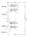
- a first marine power distribution and propulsion system 20 according to the present invention is shown in Figure 2 .
- Figure 2 A first marine power distribution and propulsion system 20 according to the present invention is shown in Figure 2 .
- the following description concentrates on systems for marine vessels, it will be readily appreciated that other power distribution systems can be implemented in a similar manner.
- the overall marine power distribution and propulsion system 20 is similar to the one shown in Figure 1 and it will be understood that any suitable number and type of ac generators, propulsion motors etc. can be used. Like components have been given the same labels or reference numerals.
- a plurality of ac generators G1...G4 provide ac power to a busbar 2 which carries a fixed-frequency distribution voltage (e.g. 690 V, 60Hz but other system voltages can be used).
- the generators G1...G4 are associated with diesel engines D1...D4 but other types of prime mover can be used.
- Electric propulsion motors M1...M4 are connected to the busbar 2 by means of interposing active front end (AFE) power converters 4, 22.
- the propulsion motors M1...M4 can be of any suitable type and construction and can optionally be configured to drive a propeller shaft or other propulsion system such as a thruster. In alternative power distribution systems then other electrical loads might be connected to the AFE power converters.
- Each AFE power converter 4, 22 includes a first active rectifier/inverter 6 having ac terminals connected to the busbar 2 and a second active rectifier/inverter 8 having ac terminals connected to the propulsion motor M1...M4.
- the dc terminals of the first and second active rectifier/inverters 6, 8 are connected together by either a conventional dc link 10 or an extended dc link 24 depending on whether the particular AFE power converter is to be provided with an additional power source.
- a harmonic filter 12 is connected to the ac terminals of the first active rectifier/inverter 6, i.e. on the network-side, to ensure harmonic voltages and currents are eliminated.
- the AFE power converters 4, 22 might, for example, be implemented as MV3000 converters supplied by GE Energy Power Conversion UK Ltd of Boughton Road, rugby, United Kingdom.
- the first active rectifier/inverter 6 will operate as an active rectifier to supply power to the dc link 10 or extended dc link 24 and the second active rectifier/inverter 8 will operate as an inverter to supply power to the associated propulsion motor M1...M4.
- reverse operation can be possible in certain circumstances such as regenerative braking for the propulsion motors M1...M4.
- the propulsion motors M1...M4 generate power which can be fed back to the busbar 2.
- the second active/rectifier 8 will operate as an active rectifier to supply the generated power to the dc link 10 and the first active rectifier/inverter 6 will operate as an inverter to supply power to the busbar 2.
- Each active rectifier/inverter 6, 8 will typically have a suitable topology with semiconductor power switching devices fully controlled and regulated using a pulse width modulation (PWM) strategy.
- PWM pulse width modulation
- the busbar 2 is equipped with protective switchgear with circuit breakers and associated controls.
- the busbar 2 is divided into a pair of busbars sections 2a, 2b (e.g. port and starboard) that are interconnected by a tie 14.
- the actual arrangement of the power distribution system will typically depend on redundancy, which is particularly important for marine vessels.
- the generators G1...G4 and AFE power converters 4, 22 can be connected to the busbar 2 by circuit breakers 16, 18 and associated controls or other switching means.
- a second busbar 26 carries a fixed-frequency distribution voltage (e.g. 480 V, 60 Hz but other system voltage and frequencies can be used).
- the second busbar 26 is equipped with protective switchgear with circuit breakers and associated controls.
- the second busbar 26 is divided into a pair of busbar sections 26a, 26b (e.g. port and starboard) that are interconnected by a tie 28.
- the first busbar sections 2a, 26a are connected together by a first step-down transformer 30a and the second busbar sections 2b, 26b are connected together by a second step-down transformer 30b.
- the first and second transformers 30a, 30b are connected to the respective busbars by circuit breakers 32 and associated controls or other switching means.
- the AFE power converters 22 associated with propulsion motors M1 and M3 have extended dc links 24.
- First and second power sources PS1, PS2 are connected in parallel to the extended dc link 24 of the AFE power converter associated with propulsion motor M1.
- a third power source PS3 is connected to the extended dc link 24 of the AFE power converter associated with propulsion motor M3.
- the first power source PS1 provides an additional dc power supply and is connected to the extended dc link 24 by means of a DC/DC power converter 34.
- the first power source PS1 can be a battery and is capable of being charged from the extended dc link 24 as well as discharging power into the extended dc link.
- the second power source PS2 provides an additional ac power supply and is connected to the extended dc link 24 by means of an AC/DC power converter 36.
- the second power source PS2 can be an auxiliary ac generator with an associated prime mover such as a diesel engine. It will be readily appreciated that the second power source PS2 is only capable of exporting power to the extended dc link 24 and cannot be charged.
- the third power source PS3 provides an additional dc power supply and is connected to the extended dc link 24 by means of a DC/DC power converter 38.
- the third power source PS3 can be a battery and, like the first power source PS1, is capable of being charged from the extended dc link 24 as well as discharging power into the extended dc link.
- the third power source PS3 is also connected to an external supply or power source 40 such as a ship to shore connection or the like by means of a power converter 42.
- the power converter 42 can either be a DC/DC or AC/DC power converter depending on the output of the external power source 40.
- a similar external power source could also be connected to the extended dc link 24, optionally by means of a suitable power converter.
- the power converter 42 could be connected to the extended dc link 24 so that power from the external power source 40 is exported directly into the extended dc link instead of being used to charge the third power source PS3.
- the DC/DC power converter 38 is connected to the extended dc link 24 by a switch 44 and the power converter 42 is connected to the third power source PS3 by a switch 46.
- the switch 44 can be opened to isolate the third power source PS3 from the extended dc link 24 when it is being charged by the external power source 40.
- the switch 46 can be opened to isolate the third power source PS3 from the external power source 40 when it is supplying power to or receiving power from the extended dc link 24.
- the power sources PS1...PS3 and their interposing power converters are controlled by individual controllers (not shown) interfaced together and to a power management controller or power management system (PMS) for the marine power distribution and propulsion system.
- the first power source PS 1 and its interposing power converter 34 can be controlled to provide one or more of the power flow modes summarised in Tables 1 and 2 above. For example, power can flow to the first power source PS1 through the extended dc link 24 from one or both of the busbar 2 and the propulsion motor M1 if operating in a regenerative mode to charge the first power source, and power can flow from the first power source PS1 through the extended dc link to one or both of the busbar and the propulsion motor M1.
- the third power source PS3 and its interposing power converter 38 can be controlled to provide one or more of the power flow modes summarised in Tables 1 and 2 above.
- power can flow through the extended dc link to the third power source PS3 from one or both of the busbar 2 and the propulsion motor M3 if operating in a regenerative mode to charge the third power source, and power can flow from the third power source PS3 through the extended dc link to one or both of the busbar and the propulsion motor M3.
- the third power source PS3 can also be charged by the external power source 40 through the power converter 42.
- the second power source PS2 and its interposing power converter 36 can be controlled to provide one or more of the power flow modes summarised in Table 1 above.
- power can flow from the second power source PS2 through the extended dc link 24 to one or both of the busbar 2 and the propulsion motor M1.
- the power sources PS1...PS3 can be operated simultaneously under the control of the power management controller or PMS.
- AFE power converters 22 can be operated in a conventional manner, i.e. where the power sources PS1...PS3 are not operational.
- the power sources PS1...PS3 can also be disabled as shown in Table 3 above.
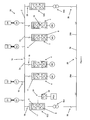
- a second marine power distribution and propulsion system 50 according to the present invention is shown in Figure 3 .
- the third marine power distribution and propulsion system 50 is similar to the one shown in Figure 2 and like components have been given the same labels or reference numerals.
- the busbar 2 carries a variable-frequency distribution voltage (e.g. 690 V but other system voltages can be used).
- the power management controller or PMS can be adapted to vary the rotational speed of the diesel engines D1...D4 with reference to the electrical load on the busbar 2 such that the ac generators G1...G4 provide a variable frequency output during normal operation of the power distribution system.
- the second busbar 26 carries a fixed-frequency distribution voltage (e.g. 480 V, 60 Hz but other system voltage and frequencies can be used).
- a fixed-frequency distribution voltage e.g. 480 V, 60 Hz but other system voltage and frequencies can be used.
- the first busbar sections 2a, 26a are connected together by a first AFE power converter 52a and a first step-down transformer 54a and the second busbar sections 2b, 26b are connected together by a second AFE power converter 52b and a second step-down transformer 54b.
- the AFE power converters 52a, 52b and the step-down transformers 54a, 54b are connected to the respective busbar by circuit breakers 56 and associated controls or other switching means.
- the first AFE power converter 52a has an extended dc link 24 to which a fourth power source PS4 is connected by means of a DC/DC converter 58.
- the fourth power source is a battery and defines an additional dc power supply.
- a fifth power source could also be connected to an extended dc link of the second AFE power converter 52b.
- Power sources could also be connected to the AFE power converters associated with propulsion motors M1...M4 is provided with an extended dc link as described above. It will be readily appreciated that the particular arrangement of power sources shown in Figure 3 is not intended to be a practical implementation and is provided only for the purposes of illustrating the technical features of the present invention.
- the fourth power source PS4 and its interposing power converter 58 are controlled by individual controllers (not shown) interfaced together and to a power management controller or PMS.
- the fourth power source PS4 and its interposing power converter 58 can be controlled such that power flows to the fourth power source through the extended dc link 24 from one or both of the busbars 2, 26 to charge the fourth power source and such that power can flow from the fourth power source through the extended dc link to one or both of the busbars 2, 26.
Landscapes
- Engineering & Computer Science (AREA)
- Power Engineering (AREA)
- Inverter Devices (AREA)
Claims (15)
- Leistungsverteilungssystem (20; 50) aufweisend:eine Wechselspannungssammelschiene (2);einen Wandler (22; 52a) aufweisend einen ersten aktiven Gleichrichter/Inverter (6) mit Wechselspannungsanschlüssen und Gleichspannungsanschlüssen, wobei die Wechselspannungsanschlüsse mit der Wechselspannungssammelschiene (2) verbunden sind, und einen zweiten aktiven Gleichrichter/Inverter (8) mit Wechselspannungsanschlüssen und Gleichspannungsanschlüssen, wobei die Wechselspannungsanschlüsse mit einer elektrischen Last (M1; 26) verbunden sind, wobei die Gleichspannungsanschlüsse des ersten und zweiten aktiven Gleichrichters/Inverters mittels eines Gleichspannungszwischenkreises (24) miteinander verbunden sind; undgekennzeichnet durch eine Leistungsquelle (PS1, PS2; PS4), die mit dem Gleichspannungszwischenkreis (24) verbunden ist und derart betrieben wird, dass sie Leistung wahlweise mittels des ersten aktiven Gleichrichters/ Inverters (6) für die Wechselspannungssammelschiene (2) und/oder mittels des zweiten aktiven Gleichrichters/Inverters (8) für die elektrische Last (M1; 26) bereitstellt.
- Leistungsverteilungssystem (20) nach Anspruch 1, wobei die Leistungsquelle (PS2) eine energieerzeugende Einrichtung ist.
- Leistungsverteilungssystem (20) nach Anspruch 1 oder 2, wobei die Leistungsquelle (PS2) derart gesteuert ist, dass sie einen oder mehrere der nachfolgenden Leistungsflussmodi bereitstellt:(i) Leistung fließt nur von der Leistungsquelle (PS2) zu der Wechselspannungssammelschiene (2),(ii) Leistung fließt nur von der Leistungsquelle (PS2) zu der elektrischen Last (M1),(iii) Leistung fließt sowohl von der Wechselspannungssammelschiene (2) als auch von der Leistungsquelle (PS2) zu der elektrischen Last (M1),(iv) Leistung fließt sowohl von der Leistungsquelle (PS2) als auch der elektrischen Last (M1) zu der Wechselspannungssammelschiene (2), und(v) Leistung fließt von der Leistungsquelle (PS2) sowohl zu der Wechselspannungssammelschiene (2) als auch zu der elektrischen Last (M1).
- Leistungsverteilungssystem (20; 50) nach Anspruch 1, wobei die Leistungsquelle (PS1; PS4) eine Energiespeicher- und Abgabeeinrichtung ist, die betrieben wird, um Leistung wahlweise mittels des ersten aktiven Gleichrichters/Inverters (6) für die Wechselspannungssammelschiene (2) und/oder mittels des zweiten aktiven Gleichrichters/Inverters (8) für die elektrische Last (M1; 26) bereitzustellen und um Leistung wahlweise über den ersten aktiven Gleichrichter/Inverter (6) von der Wechselspannungssammelschiene (2) und/oder über den zweiten aktiven Gleichrichter/Inverter (8) von der elektrischen Last (M1; 26) zu erhalten.
- Leistungsverteilungssystem (20; 50) nach Anspruch 4, wobei die Leistungsquelle (PS1; PS4) gesteuert wird, um einen oder mehrere der nachfolgenden Leistungsflussmodi bereitzustellen:(i) Leistung fließt nur von der Leistungsquelle (PS1; PS4) zu der Wechselspannungssammelschiene (2),(ii) Leistung fließt nur von der Leistungsquelle (PS1; PS4) zu der elektrischen Last (M1; 26),(iii) Leistung fließt sowohl von der Wechselspannungssammelschiene (2) als auch von der Leistungsquelle (PS1; PS4) zu der elektrischen Last (M1; 26),(iv) Leistung fließt sowohl von der Leistungsquelle (PS1; PS4) als auch von der elektrischen Last (M1; 26) zu der Wechselspannungssammelschiene (2),(v) Leistung fließt von der Leistungsquelle (PS1; PS4) sowohl zu der Wechselspannungssammelschiene (2) als auch zu der elektrischen Last (M1; 26),(vi) Leistung fließt nur von der Wechselspannungssammelschiene (2) zu der Leistungsquelle (PS1; PS4),(vii) Leistung fließt nur von der elektrischen Last (M1; 26) zu der Leistungsquelle (PS1; PS4),(viii) Leistung fließt von der Wechselspannungssammelschiene (2) sowohl zu der elektrischen Last (M1; 26) als auch zu der Leistungsquelle (PS1; PS4),(ix) Leistung fließt von der elektrischen Last (M1; 26) sowohl zu der Wechselspannungssammelschiene (2) als auch zu der Leistungsquelle (PS1; PS4), und(x) Leistung fließt sowohl von der Wechselspannungssammelschiene (2) also auch von der elektrischen Last (M1; 26) zu der Leistungsquelle (PS1; PS4).
- Leistungsverteilungssystem (29) nach Anspruch 4 oder 5, wobei die Leistungsquelle (PS3) mit einer anderen Leistungsquelle (40) verbunden ist, optional mittels eines Wandlers (42).
- Leistungsverteilungssystem (20; 50) nach einem der vorhergehenden Ansprüche, ferner aufweisend einen Wandler (34; 58), der zwischen die Leistungsquelle (PS1; PS4) und den Gleichspannungszwischenkreis (24) geschaltet ist.
- Leistungsverteilungssystem (20; 50) nach einem der vorhergehenden Ansprüche, wobei der Gleichspannungszwischenkreis (22) keine Drosselspule aufweist.
- Leistungsverteilungssystem (20; 50) nach einem der vorhergehenden Ansprüche, wobei die Verbindung zwischen den Wechselspannungsanschlüssen des ersten aktiven Gleichrichters/Inverters (6) und der Wechselspannungssammelschiene (2) keinen Transformator aufweist.
- Leistungsverteilungssystem (20; 50) nach einem der vorgehenden Ansprüche, ferner aufweisend einen Wechselspannungsgenerator (G1), der mit der Wechselspannungssammelschiene (2) verbunden ist und einen zugeordneten Antriebsmotor (D1) aufweist.
- Leistungsverteilungssystem (20) nach einem der vorhergehenden Ansprüche, wobei die elektrische Last ein Antriebsaggregat oder ein Strahlruderaggregat (M1) ist.
- Leistungsverteilungssystem (50) nach einem der Ansprüche 1 bis 10, wobei an der Wechselspannungssammelschiene (2) eine Versorgungsspannung mit variabler Frequenz anliegt und die elektrische Last eine zweite Wechselspannungssammelschiene (26) ist, an der eine Versorgungsspannung mit unveränderlicher Frequenz anliegt.
- Leistungsverteilungssystem nach Anspruch 12, wobei die Wechselspannungsanschlüsse des zweiten aktiven Gleichrichters/Inverters (8) mittels eines Transformators (54a) mit der zweiten Wechselspannungssammelschiene (26) verbunden sind.
- Verfahren zum Betreiben eines Leistungsverteilungssystems (20; 50) aufweisend:eine Wechselspannungssammelschiene (2);einen Wandler (22; 52a) aufweisend einen ersten aktiven Gleichrichter/Inverter (6) mit Wechselspannungsanschlüssen und Gleichspannungsanschlüssen, wobei die Wechselspannungsanschlüsse mit der Wechselspannungssammelschiene (2) verbunden sind, und einen zweiten aktiven Gleichrichter/Inverter (8) mit Wechselspannungsanschlüssen und Gleichspannungsanschlüssen, wobei die Wechselspannungsanschlüsse mit einer elektrischen Last (M1; 26) verbunden sind, wobei die Gleichspannungsanschlüsse des ersten und zweiten aktiven Gleichrichters/Inverters mittels einen Gleichspannungszwischenkreises (24) miteinander verbunden sind;wobei das Verfahren gekennzeichnet ist durch eine Leistungsquelle (PS1, PS2; PS4) die mit dem Gleichspannungszwischenkreis (24) verbunden ist und einen Schritt des Steuerns der Leistungsquelle (PS1, PS2; PS4) um wahlweise Leistung mittels des ersten aktiven Gleichrichters/Inverters (6) für die Wechselspannungssammelschiene (2) und/oder mittels des zweiten aktiven Gleichrichters/Inverters (8) für die elektrische Last (M1; 26) bereitzustellen.
- Verfahren nach Anspruch 14, wobei die Leistungsquelle (PS1; PS4) eine Energiespeicher- und Abgabeeinrichtung ist, und wobei das Verfahren ferner den Schritt des Steuerns der Leistungsquelle (PS1; PS4) aufweist, um wahlweise Leistung mittels des ersten aktiven Gleichrichters/Inverters (6) von der Wechselspannungssammelschiene (2) und/oder mittels des zweiten aktiven Gleichrichters/Inverters (8) von der elektrischen Last (M1; 26) zu erhalten.
Priority Applications (4)
| Application Number | Priority Date | Filing Date | Title |
|---|---|---|---|
| EP20120184692 EP2709229B1 (de) | 2012-09-17 | 2012-09-17 | Stromverteilungssysteme |
| CA 2826932 CA2826932A1 (en) | 2012-09-17 | 2013-09-12 | Power distribution systems |
| CN201310423679.0A CN103762613B (zh) | 2012-09-17 | 2013-09-17 | 配电系统 |
| US14/028,780 US10770895B2 (en) | 2012-09-17 | 2013-09-17 | Power distribution systems |
Applications Claiming Priority (1)
| Application Number | Priority Date | Filing Date | Title |
|---|---|---|---|
| EP20120184692 EP2709229B1 (de) | 2012-09-17 | 2012-09-17 | Stromverteilungssysteme |
Publications (2)
| Publication Number | Publication Date |
|---|---|
| EP2709229A1 EP2709229A1 (de) | 2014-03-19 |
| EP2709229B1 true EP2709229B1 (de) | 2015-03-25 |
Family
ID=47010237
Family Applications (1)
| Application Number | Title | Priority Date | Filing Date |
|---|---|---|---|
| EP20120184692 Revoked EP2709229B1 (de) | 2012-09-17 | 2012-09-17 | Stromverteilungssysteme |
Country Status (4)
| Country | Link |
|---|---|
| US (1) | US10770895B2 (de) |
| EP (1) | EP2709229B1 (de) |
| CN (1) | CN103762613B (de) |
| CA (1) | CA2826932A1 (de) |
Families Citing this family (75)
| Publication number | Priority date | Publication date | Assignee | Title |
|---|---|---|---|---|
| US10424935B2 (en) | 2009-09-15 | 2019-09-24 | Rajiv Kumar Varma | Multivariable modulator controller for power generation facility |
| US10232332B2 (en) | 2012-11-16 | 2019-03-19 | U.S. Well Services, Inc. | Independent control of auger and hopper assembly in electric blender system |
| US9995218B2 (en) | 2012-11-16 | 2018-06-12 | U.S. Well Services, LLC | Turbine chilling for oil field power generation |
| US11449018B2 (en) | 2012-11-16 | 2022-09-20 | U.S. Well Services, LLC | System and method for parallel power and blackout protection for electric powered hydraulic fracturing |
| US11476781B2 (en) | 2012-11-16 | 2022-10-18 | U.S. Well Services, LLC | Wireline power supply during electric powered fracturing operations |
| US10407990B2 (en) | 2012-11-16 | 2019-09-10 | U.S. Well Services, LLC | Slide out pump stand for hydraulic fracturing equipment |
| US9893500B2 (en) | 2012-11-16 | 2018-02-13 | U.S. Well Services, LLC | Switchgear load sharing for oil field equipment |
| US9745840B2 (en) | 2012-11-16 | 2017-08-29 | Us Well Services Llc | Electric powered pump down |
| WO2015020531A1 (en) * | 2013-08-06 | 2015-02-12 | Rolls-Roys Marine As | Dynamic positioning vessel |
| CN206086406U (zh) * | 2013-10-02 | 2017-04-12 | Lt350有限公司 | 篷和太阳能篷 |
| US10587015B2 (en) | 2013-10-02 | 2020-03-10 | Lt350, Llc | Energy storage canopy |
| US11916205B2 (en) | 2013-10-02 | 2024-02-27 | Lt 350, Llc | Energy storage canopy |
| EP2887484B1 (de) * | 2013-12-20 | 2023-06-28 | Abb Ag | Schaltanlagenanordnung für Wechsel- und Gleichstrom-Leistungsverteilung |
| US20150183330A1 (en) * | 2013-12-30 | 2015-07-02 | Electric Power Research Institute, Inc. | Modular reconfigurable medium voltage transformer for data centers, volt/var control, ac and dc charging, and vehicle-to-grid applications |
| EP2930815B1 (de) | 2014-04-10 | 2018-11-14 | GE Energy Power Conversion Technology Ltd | Stromverteilungssysteme |
| CA2908276C (en) | 2014-10-14 | 2022-11-01 | Us Well Services Llc | Parallel power and blackout protection for electric hydraulic fracturing |
| ES2622380T3 (es) * | 2014-10-27 | 2017-07-06 | Abb Schweiz Ag | Sistema de generación de energía eléctrica |
| EP3035477A1 (de) | 2014-12-19 | 2016-06-22 | ABB Technology Ltd | Antriebssystem mit zentralem Energiespeichersystem und Verfahren zur Steuerung der Stromübertragung in einem Stromversorgungssystem |
| DK201500424A1 (en) * | 2015-02-20 | 2016-09-12 | Maersk Drilling As | Energy generation and storage system for drilling rigs |
| DK3259821T3 (da) | 2015-02-20 | 2019-05-13 | Maersk Drilling As | Strømgenererings- og distributionssystem til offshore boreenheder |
| EP3086432B1 (de) * | 2015-04-23 | 2018-07-18 | GE Energy Power Conversion Technology Ltd | Stromverteilungssysteme |
| CN104802975A (zh) * | 2015-04-30 | 2015-07-29 | 中国船舶重工集团公司第七一二研究所 | 用于小型游船单相供电的电力推进电路 |
| EP3109964A1 (de) * | 2015-06-26 | 2016-12-28 | Siemens Aktiengesellschaft | Gleichstromnetz |
| US10008856B2 (en) | 2015-11-09 | 2018-06-26 | General Electric Company | Power system for offshore applications |
| US12078110B2 (en) | 2015-11-20 | 2024-09-03 | Us Well Services, Llc | System for gas compression on electric hydraulic fracturing fleets |
| GB2547419A (en) * | 2016-02-12 | 2017-08-23 | Endersby Daniel | Vehicle dynamic position powering system and method |
| US10511169B2 (en) * | 2016-02-20 | 2019-12-17 | Electronic Power Design, Inc. | System and method for a dynamic switchable active front end—dynamic switchable active harmonic filtering system |
| EP3696936B1 (de) * | 2016-04-05 | 2021-05-26 | Danfoss Editron Oy | Wasserfahrzeug |
| US12027831B2 (en) * | 2016-04-15 | 2024-07-02 | U.S. Well Services, LLC | Switchgear load sharing for oil field equipment |
| US10074985B2 (en) | 2016-06-21 | 2018-09-11 | The Aerospace Corporation | Solar and/or wind inverter |
| CN106274508A (zh) * | 2016-08-30 | 2017-01-04 | 中车株洲电力机车有限公司 | 一种内燃动车组及其供电系统及牵引控制方法 |
| GB2554077B (en) | 2016-09-15 | 2021-05-19 | Equinor Energy As | Handling of hydrocarbons on an offshore platform |
| GB2554075B (en) | 2016-09-15 | 2021-05-19 | Equinor Energy As | Optimising fire protection for an offshore platform |
| US10411626B2 (en) | 2016-10-13 | 2019-09-10 | Halliburton Energy Services, Inc. | Dynamic generator voltage control for high power drilling and logging-while-drilling |
| CN106741792A (zh) * | 2016-12-01 | 2017-05-31 | 广州发展瑞华新能源电动船有限公司 | 一种千吨级以上电动船舶 |
| CA2987665C (en) | 2016-12-02 | 2021-10-19 | U.S. Well Services, LLC | Constant voltage power distribution system for use with an electric hydraulic fracturing system |
| US11387658B2 (en) * | 2017-03-06 | 2022-07-12 | Hubbell Incorporated | System and method for power distribution |
| GB2560378B (en) * | 2017-03-10 | 2022-05-18 | Equinor Energy As | Power supply system for an offshore platform |
| US10598258B2 (en) | 2017-12-05 | 2020-03-24 | U.S. Well Services, LLC | Multi-plunger pumps and associated drive systems |
| US10648311B2 (en) | 2017-12-05 | 2020-05-12 | U.S. Well Services, LLC | High horsepower pumping configuration for an electric hydraulic fracturing system |
| US11791636B2 (en) | 2018-05-20 | 2023-10-17 | Off The Wall Energy Inc. | Coordinated multiple device power management system |
| CA3103490A1 (en) | 2018-06-15 | 2019-12-19 | U.S. Well Services, LLC | Integrated mobile power unit for hydraulic fracturing |
| CN110858714B (zh) * | 2018-08-24 | 2024-04-19 | 阿里巴巴集团控股有限公司 | 供电系统及供电方法 |
| WO2020056258A1 (en) | 2018-09-14 | 2020-03-19 | U.S. Well Services, LLC | Riser assist for wellsites |
| CA3115650A1 (en) | 2018-10-09 | 2020-04-23 | U.S. Well Services, LLC | Electric powered hydraulic fracturing pump system with single electric powered multi-plunger pump fracturing trailers, filtration units, and slide out platform |
| EP3648294B1 (de) * | 2018-11-05 | 2022-09-14 | Damen 40 B.V. | Antriebssystem mit umrichter zwischen schaltanlagen |
| ES3021224T3 (en) * | 2018-12-14 | 2025-05-26 | Abb Schweiz Ag | A drive arrangement for a cycloidal marine propulsion unit, a cycloidal marine propulsion unit and a method of operating such a drive arrangement |
| CN109638899B (zh) * | 2019-01-23 | 2022-07-01 | 华北电力大学(保定) | 一种多台ac/dc双向功率换流器的经济最优控制方法 |
| CA3072660C (en) | 2019-02-14 | 2020-12-08 | National Service Alliance - Houston Llc | Electric driven hydraulic fracking operation |
| US10794165B2 (en) | 2019-02-14 | 2020-10-06 | National Service Alliance—Houston LLC | Power distribution trailer for an electric driven hydraulic fracking system |
| US10738580B1 (en) | 2019-02-14 | 2020-08-11 | Service Alliance—Houston LLC | Electric driven hydraulic fracking system |
| US10753165B1 (en) | 2019-02-14 | 2020-08-25 | National Service Alliance—Houston LLC | Parameter monitoring and control for an electric driven hydraulic fracking system |
| US10753153B1 (en) | 2019-02-14 | 2020-08-25 | National Service Alliance—Houston LLC | Variable frequency drive configuration for electric driven hydraulic fracking system |
| US11578577B2 (en) | 2019-03-20 | 2023-02-14 | U.S. Well Services, LLC | Oversized switchgear trailer for electric hydraulic fracturing |
| US12664487B2 (en) | 2019-03-20 | 2026-06-23 | U.S. Well Services, LLC | Damage accumulation metering for remaining useful life determination |
| TWI704744B (zh) * | 2019-03-29 | 2020-09-11 | 威達高科股份有限公司 | 使用移動機器人電池的電源橋接裝置 |
| CA3139970A1 (en) | 2019-05-13 | 2020-11-19 | U.S. Well Services, LLC | Encoderless vector control for vfd in hydraulic fracturing applications |
| WO2020251978A1 (en) | 2019-06-10 | 2020-12-17 | U.S. Well Services, LLC | Integrated fuel gas heater for mobile fuel conditioning equipment |
| US11108234B2 (en) | 2019-08-27 | 2021-08-31 | Halliburton Energy Services, Inc. | Grid power for hydrocarbon service applications |
| US11459863B2 (en) | 2019-10-03 | 2022-10-04 | U.S. Well Services, LLC | Electric powered hydraulic fracturing pump system with single electric powered multi-plunger fracturing pump |
| US11491935B2 (en) | 2019-10-25 | 2022-11-08 | Sea Clear Power Inc. | Systems and methods for distribution of power in a marine vessel, ATVS, and vehicles |
| US11009162B1 (en) | 2019-12-27 | 2021-05-18 | U.S. Well Services, LLC | System and method for integrated flow supply line |
| US12509974B2 (en) | 2019-12-27 | 2025-12-30 | U.S. Well Services, LLC | Systems and methods for fluid end health monitoring |
| US11885206B2 (en) | 2019-12-30 | 2024-01-30 | U.S. Well Services, LLC | Electric motor driven transportation mechanisms for fracturing blenders |
| US11492886B2 (en) | 2019-12-31 | 2022-11-08 | U.S. Wells Services, LLC | Self-regulating FRAC pump suction stabilizer/dampener |
| EP3907843A1 (de) * | 2020-05-06 | 2021-11-10 | ABB Schweiz AG | Schiffsversorgungssystem |
| DE102020211493A1 (de) * | 2020-09-14 | 2022-03-17 | Skf Marine Gmbh | Energieversorgungssystem |
| CN112345878A (zh) * | 2020-09-16 | 2021-02-09 | 中国船舶重工集团公司第七0四研究所 | 一种船舶供电系统电能品质在线监测与评估装置 |
| WO2022221432A1 (en) | 2021-04-15 | 2022-10-20 | Spoc Automation Inc. | Naturally load balanced redundant power conversion system |
| SE2151299A1 (en) * | 2021-10-25 | 2023-04-26 | Berg Propulsion Production Ab | Electrical power for marine vessels |
| CN114142533B (zh) * | 2021-11-30 | 2024-03-05 | 中船动力研究院有限公司 | 一种海上浮式氢工厂的能量调度方法和装置 |
| CN113998090A (zh) * | 2021-12-06 | 2022-02-01 | 国网智慧能源交通技术创新中心(苏州)有限公司 | 一种电池动力船舶的动力配置系统和船舶 |
| US12224573B2 (en) | 2022-10-26 | 2025-02-11 | Saudi Arabian Oil Company | Submarine cable system and a switching method thereof |
| US12327991B2 (en) | 2022-12-16 | 2025-06-10 | Bae Systems Controls Inc. | AC busbar for current sharing between parallelly connected semiconductor switching pairs |
| FI20245476A1 (en) * | 2024-04-16 | 2025-10-17 | Normet Oy | Electrical system, mining or tunneling machine and method for operating the electrical system |
Citations (12)
| Publication number | Priority date | Publication date | Assignee | Title |
|---|---|---|---|---|
| DE9301877U1 (de) | 1993-02-10 | 1994-03-10 | Siemens AG, 80333 München | Vorrichtung zur Energieversorgung und Verteilung, und zum Antrieb eines Unterseebootes |
| DE19739917A1 (de) | 1997-09-11 | 1999-03-18 | Siemens Ag | System zur Versorgung elektromotorischer Verbraucher mit elektrischer Energie |
| US20040069251A1 (en) | 2001-01-22 | 2004-04-15 | Wolfgang Rzadki | Energy system for watercraft |
| WO2006020667A2 (en) | 2004-08-09 | 2006-02-23 | Railpower Technologies Corp. | Locomotive power train architecture |
| US20080182466A1 (en) | 2006-10-24 | 2008-07-31 | Railpower Technologies Corp. | Marine power train system and method of storing energy in a marine vehicle |
| US20090156068A1 (en) | 2007-12-12 | 2009-06-18 | Foss Maritime Company | Hybrid propulsion systems |
| EP2371702A1 (de) | 2007-03-19 | 2011-10-05 | Cummins Generator Technologies Limited | Antriebssystem |
| US20110309677A1 (en) | 2010-06-16 | 2011-12-22 | Transocean Sedco Forex Ventures Limited | Hybrid Power Plant for Improved Efficiency and Dynamic Performance |
| EP2423103A1 (de) | 2010-08-26 | 2012-02-29 | ABB Technology AG | Elektrisches Antriebssystem eines Schiffes mit einem Energiespeichersystem |
| WO2012049441A1 (en) | 2010-10-14 | 2012-04-19 | Converteam Technology Ltd | Marine propulsion systems |
| US20120129411A1 (en) | 2009-08-21 | 2012-05-24 | Niigata Power Systems Co., Ltd. | Marine propulsion device |
| EP2482425A1 (de) | 2011-02-01 | 2012-08-01 | Siemens Aktiengesellschaft | Blackout-Durchlaufsystem |
Family Cites Families (5)
| Publication number | Priority date | Publication date | Assignee | Title |
|---|---|---|---|---|
| US20060071554A1 (en) | 2004-09-27 | 2006-04-06 | Mcnamara James L | Electrical power distribution system and method thereof |
| US8159082B2 (en) * | 2008-09-05 | 2012-04-17 | General Electric Company | Systems and methods for providing an uninterruptible power supply to a ship-service bus of a marine vessel |
| JP5512212B2 (ja) * | 2009-09-29 | 2014-06-04 | パナソニック株式会社 | 電力管理システム |
| NO332138B2 (no) * | 2009-11-09 | 2016-04-11 | Rolls Royce Marine As Power Electric Systems Bergen | Hybrid fremdriftssystem for et fartøy |
| EP2394908B1 (de) * | 2010-06-08 | 2013-03-06 | GE Energy Power Conversion Technology Limited | Stromverteilungssystem und Verfahren für seine Steuerung. |
-
2012
- 2012-09-17 EP EP20120184692 patent/EP2709229B1/de not_active Revoked
-
2013
- 2013-09-12 CA CA 2826932 patent/CA2826932A1/en not_active Abandoned
- 2013-09-17 US US14/028,780 patent/US10770895B2/en active Active
- 2013-09-17 CN CN201310423679.0A patent/CN103762613B/zh active Active
Patent Citations (12)
| Publication number | Priority date | Publication date | Assignee | Title |
|---|---|---|---|---|
| DE9301877U1 (de) | 1993-02-10 | 1994-03-10 | Siemens AG, 80333 München | Vorrichtung zur Energieversorgung und Verteilung, und zum Antrieb eines Unterseebootes |
| DE19739917A1 (de) | 1997-09-11 | 1999-03-18 | Siemens Ag | System zur Versorgung elektromotorischer Verbraucher mit elektrischer Energie |
| US20040069251A1 (en) | 2001-01-22 | 2004-04-15 | Wolfgang Rzadki | Energy system for watercraft |
| WO2006020667A2 (en) | 2004-08-09 | 2006-02-23 | Railpower Technologies Corp. | Locomotive power train architecture |
| US20080182466A1 (en) | 2006-10-24 | 2008-07-31 | Railpower Technologies Corp. | Marine power train system and method of storing energy in a marine vehicle |
| EP2371702A1 (de) | 2007-03-19 | 2011-10-05 | Cummins Generator Technologies Limited | Antriebssystem |
| US20090156068A1 (en) | 2007-12-12 | 2009-06-18 | Foss Maritime Company | Hybrid propulsion systems |
| US20120129411A1 (en) | 2009-08-21 | 2012-05-24 | Niigata Power Systems Co., Ltd. | Marine propulsion device |
| US20110309677A1 (en) | 2010-06-16 | 2011-12-22 | Transocean Sedco Forex Ventures Limited | Hybrid Power Plant for Improved Efficiency and Dynamic Performance |
| EP2423103A1 (de) | 2010-08-26 | 2012-02-29 | ABB Technology AG | Elektrisches Antriebssystem eines Schiffes mit einem Energiespeichersystem |
| WO2012049441A1 (en) | 2010-10-14 | 2012-04-19 | Converteam Technology Ltd | Marine propulsion systems |
| EP2482425A1 (de) | 2011-02-01 | 2012-08-01 | Siemens Aktiengesellschaft | Blackout-Durchlaufsystem |
Also Published As
| Publication number | Publication date |
|---|---|
| CN103762613B (zh) | 2018-02-23 |
| CN103762613A (zh) | 2014-04-30 |
| US10770895B2 (en) | 2020-09-08 |
| CA2826932A1 (en) | 2014-03-17 |
| EP2709229A1 (de) | 2014-03-19 |
| US20140077607A1 (en) | 2014-03-20 |
Similar Documents
| Publication | Publication Date | Title |
|---|---|---|
| US10770895B2 (en) | Power distribution systems | |
| US12173594B2 (en) | Fracturing system | |
| US11680472B2 (en) | Fracturing system | |
| CN110582916B (zh) | 充电系统和方法 | |
| KR101931138B1 (ko) | 선박 상에서의 전력 분배 | |
| EP2636115B1 (de) | Verfahren für den betrieb von doppelt gespeisten systemen | |
| EP2627557B1 (de) | Marines antriebssystem | |
| CN113056853B (zh) | 用于涉水设施的能量供给系统 | |
| US20230268733A1 (en) | Energy distribution system | |
| CN111409807B (zh) | 船舶交直流组网的柴电混合电力推进系统 | |
| CN216508978U (zh) | 一种无人船直流组网电力推进系统 | |
| US11146100B2 (en) | Power supply system and method | |
| CN114567012B (zh) | 风电直流送出系统及其控制方法 | |
| WO2019061803A1 (zh) | 一种船舶电力系统 | |
| CN113169551B (zh) | 具有发电机系统的用于对不同的直流电压母线馈电的第一和第二绕组系统的用于涉水设施的能量供应系统 | |
| CN117040008A (zh) | 一种海上风电场黑启动和直流送出系统及控制方法 | |
| CN212332947U (zh) | 船舶交直流组网的柴电混合电力推进系统 | |
| CN113196607B (zh) | 用于具有多个区域的涉水设施的能量供应系统 | |
| US12312930B2 (en) | Fracturing system | |
| BR102013023660A2 (pt) | Sistema de distribuição de energia e método para operar um sistema de distribuição de energia | |
| CN116667323A (zh) | 一种船舶供电系统及方法 |
Legal Events
| Date | Code | Title | Description |
|---|---|---|---|
| PUAI | Public reference made under article 153(3) epc to a published international application that has entered the european phase |
Free format text: ORIGINAL CODE: 0009012 |
|
| AK | Designated contracting states |
Kind code of ref document: A1 Designated state(s): AL AT BE BG CH CY CZ DE DK EE ES FI FR GB GR HR HU IE IS IT LI LT LU LV MC MK MT NL NO PL PT RO RS SE SI SK SM TR |
|
| AX | Request for extension of the european patent |
Extension state: BA ME |
|
| 17P | Request for examination filed |
Effective date: 20140827 |
|
| RBV | Designated contracting states (corrected) |
Designated state(s): AL AT BE BG CH CY CZ DE DK EE ES FI FR GB GR HR HU IE IS IT LI LT LU LV MC MK MT NL NO PL PT RO RS SE SI SK SM TR |
|
| RIC1 | Information provided on ipc code assigned before grant |
Ipc: H02J 4/00 20060101ALI20140918BHEP Ipc: H02J 3/00 20060101AFI20140918BHEP |
|
| GRAP | Despatch of communication of intention to grant a patent |
Free format text: ORIGINAL CODE: EPIDOSNIGR1 |
|
| INTG | Intention to grant announced |
Effective date: 20141113 |
|
| GRAS | Grant fee paid |
Free format text: ORIGINAL CODE: EPIDOSNIGR3 |
|
| GRAA | (expected) grant |
Free format text: ORIGINAL CODE: 0009210 |
|
| AK | Designated contracting states |
Kind code of ref document: B1 Designated state(s): AL AT BE BG CH CY CZ DE DK EE ES FI FR GB GR HR HU IE IS IT LI LT LU LV MC MK MT NL NO PL PT RO RS SE SI SK SM TR |
|
| REG | Reference to a national code |
Ref country code: GB Ref legal event code: FG4D |
|
| REG | Reference to a national code |
Ref country code: CH Ref legal event code: EP |
|
| REG | Reference to a national code |
Ref country code: IE Ref legal event code: FG4D |
|
| REG | Reference to a national code |
Ref country code: DE Ref legal event code: R096 Ref document number: 602012006120 Country of ref document: DE Effective date: 20150507 |
|
| REG | Reference to a national code |
Ref country code: AT Ref legal event code: REF Ref document number: 718387 Country of ref document: AT Kind code of ref document: T Effective date: 20150515 |
|
| PG25 | Lapsed in a contracting state [announced via postgrant information from national office to epo] |
Ref country code: LT Free format text: LAPSE BECAUSE OF FAILURE TO SUBMIT A TRANSLATION OF THE DESCRIPTION OR TO PAY THE FEE WITHIN THE PRESCRIBED TIME-LIMIT Effective date: 20150325 Ref country code: HR Free format text: LAPSE BECAUSE OF FAILURE TO SUBMIT A TRANSLATION OF THE DESCRIPTION OR TO PAY THE FEE WITHIN THE PRESCRIBED TIME-LIMIT Effective date: 20150325 Ref country code: SE Free format text: LAPSE BECAUSE OF FAILURE TO SUBMIT A TRANSLATION OF THE DESCRIPTION OR TO PAY THE FEE WITHIN THE PRESCRIBED TIME-LIMIT Effective date: 20150325 Ref country code: FI Free format text: LAPSE BECAUSE OF FAILURE TO SUBMIT A TRANSLATION OF THE DESCRIPTION OR TO PAY THE FEE WITHIN THE PRESCRIBED TIME-LIMIT Effective date: 20150325 |
|
| REG | Reference to a national code |
Ref country code: AT Ref legal event code: MK05 Ref document number: 718387 Country of ref document: AT Kind code of ref document: T Effective date: 20150325 |
|
| REG | Reference to a national code |
Ref country code: LT Ref legal event code: MG4D |
|
| PG25 | Lapsed in a contracting state [announced via postgrant information from national office to epo] |
Ref country code: RS Free format text: LAPSE BECAUSE OF FAILURE TO SUBMIT A TRANSLATION OF THE DESCRIPTION OR TO PAY THE FEE WITHIN THE PRESCRIBED TIME-LIMIT Effective date: 20150325 Ref country code: GR Free format text: LAPSE BECAUSE OF FAILURE TO SUBMIT A TRANSLATION OF THE DESCRIPTION OR TO PAY THE FEE WITHIN THE PRESCRIBED TIME-LIMIT Effective date: 20150626 Ref country code: LV Free format text: LAPSE BECAUSE OF FAILURE TO SUBMIT A TRANSLATION OF THE DESCRIPTION OR TO PAY THE FEE WITHIN THE PRESCRIBED TIME-LIMIT Effective date: 20150325 |
|
| REG | Reference to a national code |
Ref country code: FR Ref legal event code: PLFP Year of fee payment: 4 |
|
| PG25 | Lapsed in a contracting state [announced via postgrant information from national office to epo] |
Ref country code: NL Free format text: LAPSE BECAUSE OF FAILURE TO SUBMIT A TRANSLATION OF THE DESCRIPTION OR TO PAY THE FEE WITHIN THE PRESCRIBED TIME-LIMIT Effective date: 20150325 |
|
| PG25 | Lapsed in a contracting state [announced via postgrant information from national office to epo] |
Ref country code: RO Free format text: LAPSE BECAUSE OF FAILURE TO SUBMIT A TRANSLATION OF THE DESCRIPTION OR TO PAY THE FEE WITHIN THE PRESCRIBED TIME-LIMIT Effective date: 20150325 Ref country code: CZ Free format text: LAPSE BECAUSE OF FAILURE TO SUBMIT A TRANSLATION OF THE DESCRIPTION OR TO PAY THE FEE WITHIN THE PRESCRIBED TIME-LIMIT Effective date: 20150325 Ref country code: SK Free format text: LAPSE BECAUSE OF FAILURE TO SUBMIT A TRANSLATION OF THE DESCRIPTION OR TO PAY THE FEE WITHIN THE PRESCRIBED TIME-LIMIT Effective date: 20150325 Ref country code: ES Free format text: LAPSE BECAUSE OF FAILURE TO SUBMIT A TRANSLATION OF THE DESCRIPTION OR TO PAY THE FEE WITHIN THE PRESCRIBED TIME-LIMIT Effective date: 20150325 Ref country code: PT Free format text: LAPSE BECAUSE OF FAILURE TO SUBMIT A TRANSLATION OF THE DESCRIPTION OR TO PAY THE FEE WITHIN THE PRESCRIBED TIME-LIMIT Effective date: 20150727 Ref country code: EE Free format text: LAPSE BECAUSE OF FAILURE TO SUBMIT A TRANSLATION OF THE DESCRIPTION OR TO PAY THE FEE WITHIN THE PRESCRIBED TIME-LIMIT Effective date: 20150325 |
|
| PG25 | Lapsed in a contracting state [announced via postgrant information from national office to epo] |
Ref country code: IS Free format text: LAPSE BECAUSE OF FAILURE TO SUBMIT A TRANSLATION OF THE DESCRIPTION OR TO PAY THE FEE WITHIN THE PRESCRIBED TIME-LIMIT Effective date: 20150725 Ref country code: PL Free format text: LAPSE BECAUSE OF FAILURE TO SUBMIT A TRANSLATION OF THE DESCRIPTION OR TO PAY THE FEE WITHIN THE PRESCRIBED TIME-LIMIT Effective date: 20150325 Ref country code: AT Free format text: LAPSE BECAUSE OF FAILURE TO SUBMIT A TRANSLATION OF THE DESCRIPTION OR TO PAY THE FEE WITHIN THE PRESCRIBED TIME-LIMIT Effective date: 20150325 |
|
| REG | Reference to a national code |
Ref country code: DE Ref legal event code: R026 Ref document number: 602012006120 Country of ref document: DE |
|
| PLBI | Opposition filed |
Free format text: ORIGINAL CODE: 0009260 |
|
| PG25 | Lapsed in a contracting state [announced via postgrant information from national office to epo] |
Ref country code: DK Free format text: LAPSE BECAUSE OF FAILURE TO SUBMIT A TRANSLATION OF THE DESCRIPTION OR TO PAY THE FEE WITHIN THE PRESCRIBED TIME-LIMIT Effective date: 20150325 |
|
| PLAX | Notice of opposition and request to file observation + time limit sent |
Free format text: ORIGINAL CODE: EPIDOSNOBS2 |
|
| 26 | Opposition filed |
Opponent name: ABB TECHNOLOGY LTD. Effective date: 20151223 |
|
| PG25 | Lapsed in a contracting state [announced via postgrant information from national office to epo] |
Ref country code: IT Free format text: LAPSE BECAUSE OF FAILURE TO SUBMIT A TRANSLATION OF THE DESCRIPTION OR TO PAY THE FEE WITHIN THE PRESCRIBED TIME-LIMIT Effective date: 20150325 Ref country code: MC Free format text: LAPSE BECAUSE OF FAILURE TO SUBMIT A TRANSLATION OF THE DESCRIPTION OR TO PAY THE FEE WITHIN THE PRESCRIBED TIME-LIMIT Effective date: 20150325 Ref country code: LU Free format text: LAPSE BECAUSE OF FAILURE TO SUBMIT A TRANSLATION OF THE DESCRIPTION OR TO PAY THE FEE WITHIN THE PRESCRIBED TIME-LIMIT Effective date: 20150917 |
|
| REG | Reference to a national code |
Ref country code: CH Ref legal event code: PL |
|
| PLAF | Information modified related to communication of a notice of opposition and request to file observations + time limit |
Free format text: ORIGINAL CODE: EPIDOSCOBS2 |
|
| PG25 | Lapsed in a contracting state [announced via postgrant information from national office to epo] |
Ref country code: SI Free format text: LAPSE BECAUSE OF FAILURE TO SUBMIT A TRANSLATION OF THE DESCRIPTION OR TO PAY THE FEE WITHIN THE PRESCRIBED TIME-LIMIT Effective date: 20150325 |
|
| REG | Reference to a national code |
Ref country code: IE Ref legal event code: MM4A |
|
| PG25 | Lapsed in a contracting state [announced via postgrant information from national office to epo] |
Ref country code: IE Free format text: LAPSE BECAUSE OF NON-PAYMENT OF DUE FEES Effective date: 20150917 Ref country code: CH Free format text: LAPSE BECAUSE OF NON-PAYMENT OF DUE FEES Effective date: 20150930 Ref country code: LI Free format text: LAPSE BECAUSE OF NON-PAYMENT OF DUE FEES Effective date: 20150930 |
|
| PLBB | Reply of patent proprietor to notice(s) of opposition received |
Free format text: ORIGINAL CODE: EPIDOSNOBS3 |
|
| PG25 | Lapsed in a contracting state [announced via postgrant information from national office to epo] |
Ref country code: BE Free format text: LAPSE BECAUSE OF FAILURE TO SUBMIT A TRANSLATION OF THE DESCRIPTION OR TO PAY THE FEE WITHIN THE PRESCRIBED TIME-LIMIT Effective date: 20150325 |
|
| REG | Reference to a national code |
Ref country code: FR Ref legal event code: PLFP Year of fee payment: 5 |
|
| PG25 | Lapsed in a contracting state [announced via postgrant information from national office to epo] |
Ref country code: MT Free format text: LAPSE BECAUSE OF FAILURE TO SUBMIT A TRANSLATION OF THE DESCRIPTION OR TO PAY THE FEE WITHIN THE PRESCRIBED TIME-LIMIT Effective date: 20150325 |
|
| PG25 | Lapsed in a contracting state [announced via postgrant information from national office to epo] |
Ref country code: SM Free format text: LAPSE BECAUSE OF FAILURE TO SUBMIT A TRANSLATION OF THE DESCRIPTION OR TO PAY THE FEE WITHIN THE PRESCRIBED TIME-LIMIT Effective date: 20150325 Ref country code: BG Free format text: LAPSE BECAUSE OF FAILURE TO SUBMIT A TRANSLATION OF THE DESCRIPTION OR TO PAY THE FEE WITHIN THE PRESCRIBED TIME-LIMIT Effective date: 20150325 Ref country code: NO Free format text: LAPSE BECAUSE OF FAILURE TO SUBMIT A TRANSLATION OF THE DESCRIPTION OR TO PAY THE FEE WITHIN THE PRESCRIBED TIME-LIMIT Effective date: 20150625 Ref country code: HU Free format text: LAPSE BECAUSE OF FAILURE TO SUBMIT A TRANSLATION OF THE DESCRIPTION OR TO PAY THE FEE WITHIN THE PRESCRIBED TIME-LIMIT; INVALID AB INITIO Effective date: 20120917 |
|
| PG25 | Lapsed in a contracting state [announced via postgrant information from national office to epo] |
Ref country code: CY Free format text: LAPSE BECAUSE OF FAILURE TO SUBMIT A TRANSLATION OF THE DESCRIPTION OR TO PAY THE FEE WITHIN THE PRESCRIBED TIME-LIMIT Effective date: 20150325 |
|
| REG | Reference to a national code |
Ref country code: FR Ref legal event code: PLFP Year of fee payment: 6 |
|
| RIC2 | Information provided on ipc code assigned after grant |
Ipc: H02J 3/00 20060101ALI20171220BHEP Ipc: H04B 5/00 20060101ALI20171220BHEP Ipc: H02J 7/00 20060101AFI20171220BHEP Ipc: H02J 4/00 20060101ALI20171220BHEP |
|
| PG25 | Lapsed in a contracting state [announced via postgrant information from national office to epo] |
Ref country code: TR Free format text: LAPSE BECAUSE OF FAILURE TO SUBMIT A TRANSLATION OF THE DESCRIPTION OR TO PAY THE FEE WITHIN THE PRESCRIBED TIME-LIMIT Effective date: 20150325 Ref country code: MK Free format text: LAPSE BECAUSE OF FAILURE TO SUBMIT A TRANSLATION OF THE DESCRIPTION OR TO PAY THE FEE WITHIN THE PRESCRIBED TIME-LIMIT Effective date: 20150325 |
|
| APAH | Appeal reference modified |
Free format text: ORIGINAL CODE: EPIDOSCREFNO |
|
| APBM | Appeal reference recorded |
Free format text: ORIGINAL CODE: EPIDOSNREFNO |
|
| APBP | Date of receipt of notice of appeal recorded |
Free format text: ORIGINAL CODE: EPIDOSNNOA2O |
|
| REG | Reference to a national code |
Ref country code: FR Ref legal event code: PLFP Year of fee payment: 7 |
|
| APBQ | Date of receipt of statement of grounds of appeal recorded |
Free format text: ORIGINAL CODE: EPIDOSNNOA3O |
|
| PG25 | Lapsed in a contracting state [announced via postgrant information from national office to epo] |
Ref country code: AL Free format text: LAPSE BECAUSE OF FAILURE TO SUBMIT A TRANSLATION OF THE DESCRIPTION OR TO PAY THE FEE WITHIN THE PRESCRIBED TIME-LIMIT Effective date: 20150325 |
|
| PGFP | Annual fee paid to national office [announced via postgrant information from national office to epo] |
Ref country code: FR Payment date: 20210819 Year of fee payment: 10 |
|
| PGFP | Annual fee paid to national office [announced via postgrant information from national office to epo] |
Ref country code: DE Payment date: 20210818 Year of fee payment: 10 Ref country code: GB Payment date: 20210820 Year of fee payment: 10 |
|
| REG | Reference to a national code |
Ref country code: DE Ref legal event code: R103 Ref document number: 602012006120 Country of ref document: DE Ref country code: DE Ref legal event code: R064 Ref document number: 602012006120 Country of ref document: DE |
|
| APBU | Appeal procedure closed |
Free format text: ORIGINAL CODE: EPIDOSNNOA9O |
|
| RDAF | Communication despatched that patent is revoked |
Free format text: ORIGINAL CODE: EPIDOSNREV1 |
|
| STAA | Information on the status of an ep patent application or granted ep patent |
Free format text: STATUS: PATENT REVOKED |
|
| RDAG | Patent revoked |
Free format text: ORIGINAL CODE: 0009271 |
|
| 27W | Patent revoked |
Effective date: 20220711 |
|
| GBPR | Gb: patent revoked under art. 102 of the ep convention designating the uk as contracting state |
Effective date: 20220711 |
|
| REG | Reference to a national code |
Ref country code: FI Ref legal event code: MGE |