EP2709381A2 - Haut-parleur miniature à puissance élevée - Google Patents
Haut-parleur miniature à puissance élevée Download PDFInfo
- Publication number
- EP2709381A2 EP2709381A2 EP12786481.7A EP12786481A EP2709381A2 EP 2709381 A2 EP2709381 A2 EP 2709381A2 EP 12786481 A EP12786481 A EP 12786481A EP 2709381 A2 EP2709381 A2 EP 2709381A2
- Authority
- EP
- European Patent Office
- Prior art keywords
- damper
- microspeaker
- output
- fpcb
- diaphragm
- Prior art date
- Legal status (The legal status is an assumption and is not a legal conclusion. Google has not performed a legal analysis and makes no representation as to the accuracy of the status listed.)
- Granted
Links
Images


Classifications
-
- H—ELECTRICITY
- H04—ELECTRIC COMMUNICATION TECHNIQUE
- H04R—LOUDSPEAKERS, MICROPHONES, GRAMOPHONE PICK-UPS OR LIKE ACOUSTIC ELECTROMECHANICAL TRANSDUCERS; ELECTRIC HEARING AIDS; PUBLIC ADDRESS SYSTEMS
- H04R9/00—Transducers of moving-coil, moving-strip, or moving-wire type
- H04R9/02—Details
-
- H—ELECTRICITY
- H04—ELECTRIC COMMUNICATION TECHNIQUE
- H04R—LOUDSPEAKERS, MICROPHONES, GRAMOPHONE PICK-UPS OR LIKE ACOUSTIC ELECTROMECHANICAL TRANSDUCERS; ELECTRIC HEARING AIDS; PUBLIC ADDRESS SYSTEMS
- H04R9/00—Transducers of moving-coil, moving-strip, or moving-wire type
- H04R9/02—Details
- H04R9/04—Construction, mounting, or centering of coil
- H04R9/041—Centering
- H04R9/043—Inner suspension or damper, e.g. spider
-
- H—ELECTRICITY
- H04—ELECTRIC COMMUNICATION TECHNIQUE
- H04R—LOUDSPEAKERS, MICROPHONES, GRAMOPHONE PICK-UPS OR LIKE ACOUSTIC ELECTROMECHANICAL TRANSDUCERS; ELECTRIC HEARING AIDS; PUBLIC ADDRESS SYSTEMS
- H04R7/00—Diaphragms for electromechanical transducers; Cones
- H04R7/16—Mounting or tensioning of diaphragms or cones
- H04R7/18—Mounting or tensioning of diaphragms or cones at the periphery
- H04R7/20—Securing diaphragm or cone resiliently to support by flexible material, springs, cords, or strands
-
- H—ELECTRICITY
- H04—ELECTRIC COMMUNICATION TECHNIQUE
- H04R—LOUDSPEAKERS, MICROPHONES, GRAMOPHONE PICK-UPS OR LIKE ACOUSTIC ELECTROMECHANICAL TRANSDUCERS; ELECTRIC HEARING AIDS; PUBLIC ADDRESS SYSTEMS
- H04R9/00—Transducers of moving-coil, moving-strip, or moving-wire type
- H04R9/02—Details
- H04R9/04—Construction, mounting, or centering of coil
- H04R9/045—Mounting
Definitions
- the present invention relates to a high-output microspeaker, and more particularly, to a high-output microspeaker which includes a damper for preventing lateral vibrations of a diaphragm.
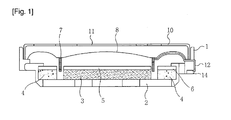
- FIG. 1 is a sectional view showing a conventional sound transducer.
- a typical sound transducer includes a frame 1, a yoke 2 inserted and mounted inside the frame 1, an inner ring magnet 3 and an outer ring magnet 4 for transmitting a magnetic flux to the yoke 2 or receiving the magnetic flux from the yoke 2, an inner ring top plate 5 and an outer ring top plate 6 for receiving the magnetic flux from the inner ring magnet 3 or the outer ring magnet 4 and transmitting the magnetic flux to a voice coil 7 at a right angle, the voice coil 7 partially inserted into air gaps between the inner ring magnet 3 and inner ring top plate 5 and the outer ring magnet 4 and outer ring top plate 6, a diaphragm 8, into which the voice coil 7 is attached, for generating a vibration by the up-down movement of the voice coil 7, and a protector 10 having a sound-emitting hole 11 and protecting the diaphragm 8.
- the lead-out wire of the voice coil 7 is fixedly adhered to the bottom face of the diaphragm 8 by a wire bond, taken out through the side face of the frame 1 or a groove (not shown) formed at the frame 1, and soldered to a terminal 14 along the outer side face of the frame 1, respectively.
- this structure has limitations in reproducing wideband sound sources.
- a film with low rigidity is used or the diaphragm is thinned, in order to improve low frequency performance, this generates dips in sound pressure at mid-to-high frequencies and particular lateral vibrations at low frequencies, thus causing an increase in defect rate.
- the diaphragm is thickened or a film with high rigidity is used, this degrades low frequency performance and results in poor sound balance.
- a film structure for a wideband speaker was conventionally proposed, in which an edge portion and a central portion are made of different film materials.
- this damper greatly affect the features and reliability of a microspeaker when configuring the damper.
- a wrongly-configured damper could be more subject to wire breakage than a voice coil lead-out structure and cause difficulties in correcting lateral vibrations at a particular mode.
- An object of the present invention is to provide a high-output microspeaker which includes a damper having a structure capable of correcting lateral vibrations of the high-output microspeaker.
- Another object of the present invention is to provide a high-output microspeaker which improves reliability by preventing the breakage of an FPCB pattern formed on a damper.
- a high-output microspeaker comprising: a frame; a protector; a yoke assembly coupled to the frame and including a magnet; a diaphragm provided in the frame and producing vibration; a voice coil coupled to the diaphragm and vibrating the diaphragm; a terminal provided on one side of the frame and providing an electrical connection between the lead wire of the voice coil and an external terminal; and a damper formed of an FPCB that includes an inner portion to which a center diaphragm, a side diaphragm and the voice coil are attached, an outer portion to which the side diaphragm is attached and which is in contact with the frame and the protector, a support portion functioning to connect the voice coil, the outer portion and the inner portion and including a land portion to which the lead-in wire of the coil is soldered or welded, and a connecting portion extending outward from the outer portion and providing an electrical connection between the terminal provided on the frame
- the terminal and the connecting portion are located on a corner of the frame, two or more projections for supporting the connecting portion are provided on the corner where the terminal and the connecting portion are located, and the connecting portion has a shape fitting to the projections.
- the connecting portion includes a horseshoe-shaped land portion for soldering or welding.
- the horseshoe-shaped land portion is formed on at least one of the top and bottom sides of the damper.
- the horseshoe-shaped land portion is formed on the bottom side of the damper, and a through hole for transmitting electrical signals to an FPCB pattern formed on the top side of the damper is formed at the boundary between the connecting portion and the outer portion.
- an FPCB pattern at the support portion is formed on either the top side or bottom side of the damper, and an FPCB pattern at the outer portion is formed on both the top and bottom sides of the damper.
- the inner portion has no FPCB pattern of the damper.
- a cover layer is formed in stress-concentrated regions of the FPCB pattern of the damper.
- the support portion has an FPCB pattern for soldering or welding the lead-in wire of the coil, and the FPCB pattern at the support portion includes a dummy pattern for forming a symmetrical structure.
- the high-output microspeaker is formed in a rectangular shape, and the support portion is formed on four edges.
- the support portion includes an outer curved portion, a linear portion and an inner curved portion and is connected from the outer portion to the inner portion.
- the width of the curved portions is greater than the width of the linear portion.
- the curved portion connected to the outer portion is inclined to one side from the center of the edge.
- the FPCB pattern of the damper includes a pair of sections, each including two neighboring support portions, and the curved portion of any one of the two support portions is spaced apart from the outer portion of the other section of the FPCB pattern.
- the width of the inner portion is greater than the sum of the size of the seating portion of the side diaphragm and the size of the attachment portion of the voice coil.
- the contour of the land portion formed at the support portion is entirely in the shape of a curve.
- the high-output microspeaker provided by the present invention can prevent lateral vibrations owing to the position and shape of the support portion of the damper and the patterning shape of an FPCB pattern.
- the high-output microspeaker provided by the present invention can prevent the breakage of a patterned FPCB circuit by forming a cover layer in stress-concentrated regions, thereby improving reliability.
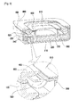
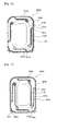
- FIG. 2 is an exploded perspective view showing a sound transducer according to a first embodiment of the present invention.
- the sound transducer according to the first embodiment includes a frame 100, a yoke 210 coupled to the bottom side of the frame 100, an inner ring magnet 220 attached to the yoke 210, an inner ring top plate 230 covering the inner ring magnet, an outer ring magnet 240 fixed to the frame 100 and the yoke 210, an outer ring top plate 250 covering the outer ring magnet 240, a voice coil 300 partially inserted between the inner ring magnet 230 and the outer ring magnet 240 and vibrating up and down according to an electrical signal, a damper 400 to which the voice coil 300 is attached and which vibrates together with the voice coil 300, a diaphragm 500 attached to the top or bottom of the damper 400 and vibrating together with the damper 400, a protector 600 that protects the internal parts, is coupled to the frame 100 to form the outer appearance, and defines an inner vibration space, and pad type
- the sound transducer further includes a short-circuit prevention member 800 interposed between the damper 400 and the protector 600.
- the term 'external terminal' refers to a portion or part that is provided in a machine equipped with a high-output sound transducer to transmit an electrical signal to the high-output sound transducer
- the term 'terminal' refers to a portion or part that is electrically connected to an external terminal to transmit an electrical signal to an FPCB, i.e., the damper 400.
- the pad type terminals 900 are employed as an example of terminals.
- the damper 400 is formed of an FPCB which is capable of transmitting an external electrical signal to the voice coil 300.
- the damper 400 formed of an FPCB is patterned to transmit (+) and (-) currents, with the voice coil 300 being connected to one end of the pattern and an external terminal being connected to the other end.
- portions that connect the damper 400 and the terminal are referred to as connecting portions 410.
- the voice coil 300 is attached to the damper 400 by soldering or the like, and the diaphragm 500 is then attached to the damper 400 with tape or other adhesives.
- the diaphragm 500 vibrates up and down only, so that abnormal vibrations such as split vibrations or lateral vibrations are prevented and sound quality is improved.
- the diaphragm 500 includes a center diaphragm 520 located at the center and a side diaphragm 520 located outside the center diaphragm 510 and formed in a ring shape.
- the center diaphragm 510 and the side diaphragm 520 are in the shape of a dome, each of which projects upward or downward.
- the center diaphragm 510 and the side diaphragm 520 generally project upward; if the overall height of the voice coil 300 becomes larger, the lower space of the damper 400 can be used as a vibration space. Accordingly, the height (size) of the high-output sound transducer can be reduced by projecting the center diaphragm 510 and the side diaphragm 520 downward.
- the center diaphragm 510 and the side diaphragm 520 may be attached to the top of the damper 400 or to the bottom thereof. In the drawing, the center diaphragm 510 is illustrated as being attached to the top of the damper, and the side diaphragm 520 is illustrated as being attached to the bottom of the damper.
- the connecting portions 410 of the damper 400 are disposed so as not to overlap the diaphragm 500 and located on the edge of the damper 400 to provide a convenient connection to a pin terminal 700. That is, the connecting portions 410 are located outside the region of the damper 400 to which the side diaphragm 520 is attached, so that the side diaphragm 520 and the connecting portions 410, which are mounted on the edge of the damper 400, do not overlap each other. Accordingly, the outer circumference of the damper 400 is longer than the outer circumference of the side diaphragm 520. With this configuration, the damper 400, the diaphragm 500, and the voice coil 300 are joined together in a jig. They can be firmly joined because they are fixed by applying constant pressure during bonding.
- the voice coil 300, the side diaphragm 520 and the center diaphragm 510 are attached to the damper 400, and the damper 400 is then seated on the frame 100 where the yoke 210, the inner ring magnet 220, the inner ring top plate 230, the outer ring magnet 240, the outer ring top plate 250 and the pin terminal 700 are mounted.
- the frame 100 includes projections 110 for helping seat the damper 400 and the diaphragm 500, and one end of the pin terminal 700 is located at a region where the connecting portion 410 is seated.
- the projections 110 are located on the corners of the frame 100.
- two or more projections 110 are formed on at least one corner so as to prevent the damper 400, the diaphragm 500 and the protector 600 from deviating up, down, left, and right.
- the projections 110 are formed on the corners where the connecting portions 410 of the damper 400 are located, and the protector 600 has portions formed to engage with the projections 110 so that the protector 600 is fixed by the projections 110.
- Each pad type terminal 900 is insert injection-molded into the frame 100 and includes a pad portion 910 that comes into contact with an external terminal and receives an electrical signal, a bonding portion 920 that is bonded to a connecting portion 410 of the damper 400 formed of an FPCB, and a bent portion 930 connecting the bonding portion 920 and the pad portion 910.
- the pad portion 910 is disposed so as to be exposed to the bottom side of the frame 100 to be in contact with the external terminal
- the bonding portion 920 is disposed so as to be exposed to a top corner of the frame 100 to be in contact with the connecting portion 410 of the damper 400.
- the pad type terminal 900 In order to integrally form the frame 100 and the pad type terminal 900 by insert injection-molding, the pad type terminal 900 should be fixed into a mold so that the pad type terminal 900 is located at a precise position, i.e., no defect is generated. While the pad portion 910 of the pad type terminal 900 requires no fixing member because it is located on the bottom side of the mold, the bonding portion 920 is spaced apart from the bottom side of the mold and therefore needs to be fixed at a precise position because, unless the bonding portion 920 is at a precise position during injection molding, the bonding portion 920 could be buried in an injection-molded product and not exposed to the outside, resulting in the production of defective products incapable of bonding.
- Injection molding should be carried out while fixing the bonding portion 920 at a precise position by applying pressure from the top and bottom.
- the bonding portion 920 can be easily pressed with a separate member because its top is open.
- the pad portion 910 exists on the same axis as the bottom of the bonding portion 920, and therefore the pad portion 910 and the bonding portion 920 should be formed not to overlap each other to apply pressure to the bonding portion 920 from the bottom.
- the pad portion 910 and the bonding portion 920 should be formed in a way that the end of the bonding portion 920 does not overlap the pad portion 910 when viewed in the height direction of the high-output sound transducer (lamination direction of parts such as the frame, the magnets, the damper, etc).
- the bonding portion 920 may be partially extended to be longer than the pad portion 910, and the pad portion 910 may be partially eliminated.
- the short-circuit prevention member 800 interposed between the damper 400 and the protector 600 will be further explained.
- the purpose of the protector 600 is to protect the voice coil 300, the damper 400 and the diaphragm 500 and generally has a sound-emitting hole perforated therein to emit a sound.
- the protector 600 is usually made of a metal because it requires sufficient strength for protection. If the protector 600 is formed of a metal, it may be brought into contact with a terminal 700 or 900 or the damper 400 formed of an FPCB, leading to short-circuit and failure. To prevent this, the short-circuit prevention member 800 made of a non-metal material is interposed between the damper 400 and the protector 600.
- the short-circuit prevention member 800 is formed in the shape of a rectangular ring so as to be in contact with the circumference of the protector 600 and prevents the protector 600 from coming into contact with the damper 400 or the terminal 700 or 900.
- the short-circuit prevention member 800 is formed integrally with the protector 600 as the protector 600 made of a metal is insert injection-molded. Instead of providing the short-circuit prevention member 800, the protector 600 may be formed of a non-conductive material.
- FIG. 3 is a sectional perspective view showing a sound transducer according to an embodiment of the present invention.
- a voice coil 300 and a diaphragm 500 are attached to a damper 400.
- the diaphragm 500 includes a center diaphragm 510 and a side diaphragm 520, and the center diaphragm 510 and the side diaphragm 520 are in the shape of a dome that projects upward or downward.
- the height of the voice coil 300 inevitably rises.
- the projecting height of the side diaphragm 520 is increased in order to enhance low frequencies.
- the center diaphragm 510 may project either upward or downward because a space provided on the top by the protector 600 can be used as the vibration space, or if the diaphragm 500 is not covered with the protector 600, a space between the high-output sound transducer and a case in which the high-output sound transducer is installed can be used as the vibration space.
- the side diaphragm 520 mounted on the same side as the voice coil 300 needs to be protected from heat generation. This is because the side diaphragm 520, which is made of a thin film and is weak to heat, can be easily deformed. Therefore, when attaching the voice coil 300 to the damper 400 by soldering or the like and attaching the side diaphragm 520 to the damper 400 via an adhesive or adhesive tape, the side diaphragm 520 is spaced a predetermined distance from the attachment position of the voice coil 300. Accordingly, the side diaphragm 520 can be protected from heat generated from the voice coil 300 during the operation of the sound transducer.
- the center diaphragm 510 and the side diaphragm 520 may be made of the same film material or different film materials as required.
- the center diaphragm 510 is made of a thermoplastic film such as PE, PP, PEN, PEI, PEEK or PET, and if necessary, can be UV-molded or the like.
- the side diaphragm 520 can be made by combining a thermoplastic film such as PE, PP, PEN, PEEK, PEI or PET and a thermoplastic urethane film such as TPU.
- the center diaphragm 510 and the side diaphragm 520 cover different sound frequency bands.
- the side diaphragm 510 can enhance the acoustic properties in the low frequency band owing to its increased ductility and elasticity, whereas the center diaphragm 510 can enhance the acoustic characteristics in the mid and high frequency bands owing to its light weight and increased rigidity.
- the outer ring top plate 250 and the frame 100 have level differences so as to engage with each other. If the outer ring top plate 250 and the frame 100 have level differences to engage with each other, less space is required to fix the outer ring top plate 250 and the frame 100, as compared to the outer ring top plate 250 and the frame 100 which do not. More specifically, the top of the outer ring top plate 250 should be covered with the frame 100 so as to fix the outer ring top plate 250 and the outer ring magnet 240. By providing level differences in the outer ring top plate 250 and the corresponding level differences in the frame 100, the height of the frame 100 projecting above the outer ring top plate 250, which is required for fixing the outer ring top plate 250, can be reduced.
- the space for vibration of the diaphragm can be further extended, thereby helping improve the output of the sound transducer and providing an advantage in miniaturizing the sound transducer.
- a leakage magnetic flux flowing from the outer ring magnet 240 toward the frame 100 can be reduced, and therefore the amount of the magnetic flux flowing between the outer ring magnet 240 and the inner ring magnet 220 can be increased, thus improving the output of the sound transducer.
- FIG. 4 is a view showing an FPCB pattern on the top side of the damper for the high-output microspeaker according to the first embodiment of the present invention
- FIG. 5 is a view showing the shape of the top side of the damper for the high-output microspeaker according to the first embodiment of the present invention
- FIG. 6 is a view showing an FPCB pattern on the bottom side of the damper for the high-output microspeaker according to the first embodiment of the present invention
- FIG. 7 is a view showing the shape of the bottom side of the damper for the high-output microspeaker according to the first embodiment of the present invention.
- the damper 400a includes an inner portion 410a to which a center diaphragm, a side diaphragm and a voice coil are attached, an outer portion 420a being in contact with a frame and a protector, and support portions 430a connecting and supporting the inner portion 410a and the outer portion 420a. Also, connecting portions 422a for connecting to terminals such as pad type terminals 900 are provided on one side of the outer portion 420a.
- the damper 400a is overall in the shape of a rectangle, and its corners are rounded.
- the outer portion 420a has a rectangular shape with corners rounded along the shape of the damper 400a and includes four sides, and the inner portion 410 likewise has a rectangular shape with rounded corners and includes four sides.
- the width of the inner portion 410a should be greater than the sum of the width of the seating portion of the side diaphragm 520 and the width of the seating portion of the voice coil 300.
- a total of four support portions 430a are provided on each side, each of which includes two ends connected to one side of the outer portion 420a and one side of the inner portion 410a, respectively.
- Each support portion 430a includes an outer curved portion 432a meeting the outer portion 420a and formed in a curve, an inner curved portion 434a meeting the inner portion 410a and formed in a curve, and a linear portion 436a formed as a straight line between the outer curved portion 432a and the inner curved portion 434a.
- the outer curved portion 432a and the inner curved portion 434a are made thicker in width than the linear portion 436a because they receive more stress than the linear portion 436a; especially, the inner curved portion 434a is made thick.
- the connecting portions 422a are formed at both ends of one side of the outer portion 420a, i.e., on the corners of one side of the outer portion 420a, and are projected further than the corners where the connecting portions 422a are not formed.
- an FPCB upper surface pattern 440a is formed only at the outer portion 420a on the top side of the damper 400a.
- the FPCB upper surface pattern 440a formed on the top side of the damper 400a is formed all over the outer portion 420a along the outer portion 420a and is divided into two sections for transmitting (+) signals and (-) signals, respectively.
- Each section of the FPCB upper surface pattern 440a includes one connecting portion 422a.
- Land portions 442a for bonding to the terminals 900 are provided at ends of the FPCB upper surface pattern 440a formed at the connecting portions 422a.
- the land portions 442a are plated for higher conduction efficiency to the terminals 900 and have a substantially horseshoe shape.
- Conducting holes 444a are formed at the boundaries between the connecting portions 422a and the outer portion 420a, inside the land portions 442a, i.e., within the FPCB upper surface pattern 440a.
- the conducting holes 444a are of a structure for transmitting the electrical signals from the FPCB upper surface pattern 440a through the land portions 442a to an FPCB lower surface pattern 450a.
- the voice coil 300 is configured to be electrically connected to the FPCB lower surface pattern 450a formed on the bottom side of the damper 400a
- the FPCB upper surface pattern 440a and the FPCB lower surface pattern 450a should be electrically connected so that the electrical signals transmitted from the terminals 900 are transmitted finally to the voice coil 300.
- the FPCB lower surface pattern 450a is formed all over the outer portion 420a, the inner portion 410a, and the support portions 430a.
- the FPCB lower surface pattern 450a is likewise divided into two sections for transmitting (+) signals and (-) signals, respectively.
- the FPCB lower surface pattern 450a is configured in a way that the outer curved portion 432a of a support portion 430a in one section is spaced apart from the pattern formed at the outer portion 420a in the other section, and the pattern formed at the inner portion 410a in one section is spaced apart from the pattern formed at the inner portion 410a in the other section.
- land portions 438a for soldering or welding the FPCB lower surface pattern 450a and the voice coil 300 are provided at the support portions 430a, more particularly, at the inner curved portions 434a of the support portions 430a.
- the contours of the land portions 438a are wholly formed in a curve so as to prevent the land portions 438a from breaking easily.
- the land portions 438a are plated with silver for higher conduction efficiency.
- the damper 400a is overall in the shape of a rectangle and includes four sides, with one support portion 430a formed on each side.
- the positions at the outer portion 420a where the support portions 430a are attached are inclined to one side of the center, all in the same direction on the four sides.
- the positions at the inner portion 410a where the support portions 430a are attached are inclined to one side of the center in a direction opposite to the direction of the support portions 430a at the outer portion 420a.
- the damper 400a has a rectangular shape, with two shorter sides and two longer sides.
- the shorter sides are referred to as the short axis
- the longer sides are referred to as the long axis.
- gaps between one of the two divided sections of the FPCB lower surface pattern 450a and the other section exist on the short axis.
- the FPCB pattern is divided into two sections.
- an outer curved portion 432a in one section of the FPCB pattern is spaced apart from the FPCB pattern formed at the outer portion 420 in the other section, which causes the FPCB pattern formed at the outer curved portions 432a of the support portions 430a located on the short axis to form a U-shaped curve.
- the FPCB lower surface pattern 450a formed on the bottom side of the damper 400a is almost the same shape as the damper 400a, except for the presence of the land portions 438a or the gaps. Accordingly, the FPCB lower surface pattern 450a, formed on the inner curved portions 434a to which stress is concentrated, likewise has a large width and therefore does not break easily, thereby increasing the reliability of the high-output microspeaker.
- the FPCB lower surface pattern 450a formed on the outer curved portions 432a located on the long axis also has a large width and does not break easily, and the FPCB pattern formed at the outer curved portions 432a located on the short axis does not break easily, although its width is not large, because it is in the shape of a U-shaped curve.
- an adhesive tape 460a is attached to the inner portion 410a in order to attach the center diaphragm 510 and the damper 400a.
- an adhesive tape 470a is attached to the outer portion 420a in order to attach the side diaphragm 520, the frame 100, and the damper 400a.
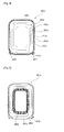
- FIG. 8 is a view showing a damper for a high-output microspeaker according to a second embodiment of the present invention.
- the second embodiment is identical to the first embodiment, except that a cover layer 480b for protecting a damper 400b is attached on the top layer of the damper 400b.
- the cover layer 480b is formed in stress-concentrated regions, and the cover layer 480b is removed from regions where little stress is applied, so as to reduce the weight of the damper 400b.
- the cover layer 480b is attached to the regions of the damper 400b that receive the most stress, including an inner portion 410b, to which the voice coil 300 is attached, and inner curved portions 434b of support portions 430.
- the cover layer 480b is attached to both the top and bottom sides of the damper 400b and functions to protect the FPCB pattern and receive the stress applied to the damper 400b.
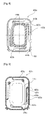
- FIG. 9 is a view showing a damper for a high-output microspeaker according to a third embodiment of the present invention.
- the third embodiment is identical to the second embodiment, except for the shape of an FPCB lower surface pattern, so descriptions of components other than the FPCB lower surface pattern will be omitted.
- an FPCB lower surface pattern 450c is formed only at an outer portion 420c and support portions 430c, but not at an inner portion 410a. While land portions 438c are formed only at two of the support portions 430c, the FPCB lower surface pattern 450c is formed at all the support portions 430c in order to form a symmetrical structure. That is, a dummy pattern is formed at two of the support portions 430c.
- the FPCB lower surface pattern 450c is configured such that the pattern width is somewhat larger at the boundaries between the regions formed on inner curved portions 434a of the support portions 430c and the inner portion 410a.
- FIG. 10 is a view showing a damper for a high-output microspeaker according to a fourth embodiment of the present invention.
- the fourth embodiment is identical to the second and third embodiments, except for the shape of an FPCB lower surface pattern, so descriptions of components other than the FPCB lower surface pattern will be omitted.
- an FPCB lower surface pattern 450d is formed only at an outer portion 420d and support portions 430d, but not at an inner portion 410d.
- land portions 438d and an FPCB pattern for connecting to the land portions 438d are formed at two of the support portions 430d, and a dummy pattern for forming a symmetrical structure is formed at the other two support portions 430d.
- the FPCB lower surface pattern 450c is different from that of the third embodiment in that the regions formed on inner curved portions 434d of the support portions 430d are slightly further extended toward the inner portion 410d and become narrower toward the inner portion 410d, as compared to the third embodiment.
- FIG. 11 is a view showing a damper for a high-output microspeaker according to a fifth embodiment of the present invention.
- the fifth embodiment is identical to the second to fourth embodiments, except for the shape of an FPCB lower surface pattern, so descriptions of components other than the FPCB lower surface pattern will be omitted.
- An FPCB lower surface pattern 450e according to the fifth embodiment is formed in some part of an inner portion 410e, an outer portion 420e, and support portions 430e. Also, land portions 438e and an FPCB pattern for connecting to the land portions 438e are formed at two of the support portions 430e, and a dummy pattern for forming a symmetrical structure is formed at the other two support portions 430e.
- the FPCB lower surface pattern 450e is likewise divided into two sections for transmitting (+) signals and (-) signals, respectively.
- Each section is provided with one FPCB pattern for connecting to the land portions 438e and one dummy pattern.
- an end of the dummy pattern in each section and an end of the FPCB pattern for connecting to the land portions 438e are extended toward the inner portion 410e and connected to each other.
- the regions extending toward the inner portion 410e are formed partially on the outer side of the inner portion 410e along the long axis.
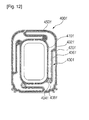
- FIG. 12 is a view showing a damper for a high-output microspeaker according to a sixth embodiment of the present invention.
- the sixth embodiment is identical to the second to fifth embodiments, except for the shape of an FPCB lower surface pattern, so descriptions of components other than the FPCB lower surface pattern will be omitted.
- An FPCB lower surface pattern 450f according to the sixth embodiment is almost identical to that of the second embodiment, but different from the second embodiment in that an FPCB pattern is formed partially on the outer side of an inner portion 410f but not on the inner side thereof. In other words, the FPCB pattern formed at the inner portion 410f is narrower than that of the second embodiment.
Landscapes
- Engineering & Computer Science (AREA)
- Physics & Mathematics (AREA)
- Acoustics & Sound (AREA)
- Signal Processing (AREA)
- Multimedia (AREA)
- Audible-Bandwidth Dynamoelectric Transducers Other Than Pickups (AREA)
Applications Claiming Priority (2)
| Application Number | Priority Date | Filing Date | Title |
|---|---|---|---|
| KR1020110045070A KR101200435B1 (ko) | 2011-05-13 | 2011-05-13 | 고출력 마이크로 스피커 |
| PCT/KR2012/003653 WO2012157888A2 (fr) | 2011-05-13 | 2012-05-10 | Haut-parleur miniature à puissance élevée |
Publications (3)
| Publication Number | Publication Date |
|---|---|
| EP2709381A2 true EP2709381A2 (fr) | 2014-03-19 |
| EP2709381A4 EP2709381A4 (fr) | 2014-09-24 |
| EP2709381B1 EP2709381B1 (fr) | 2017-11-01 |
Family
ID=47177445
Family Applications (1)
| Application Number | Title | Priority Date | Filing Date |
|---|---|---|---|
| EP12786481.7A Not-in-force EP2709381B1 (fr) | 2011-05-13 | 2012-05-10 | Haut-parleur miniature à puissance élevée |
Country Status (5)
| Country | Link |
|---|---|
| US (1) | US9025808B2 (fr) |
| EP (1) | EP2709381B1 (fr) |
| KR (1) | KR101200435B1 (fr) |
| CN (1) | CN103563397B (fr) |
| WO (1) | WO2012157888A2 (fr) |
Cited By (4)
| Publication number | Priority date | Publication date | Assignee | Title |
|---|---|---|---|---|
| EP2787744A1 (fr) * | 2013-04-03 | 2014-10-08 | Em-tech. Co., Ltd. | Enceinte mince côté haut-parleur avec structure d'émission acoustique |
| EP3035708A3 (fr) * | 2014-12-15 | 2016-09-21 | EM-Tech Co., Ltd. | Micro haut-parleur mince |
| EP3247132A4 (fr) * | 2015-03-31 | 2018-02-28 | Goertek.Ink | Appareil haut-parleur supprimant la polarisation et procédé de réglage de position d'équilibrage et de souplesse de membrane |
| CN112752200A (zh) * | 2019-10-29 | 2021-05-04 | 易音特电子株式会社 | 用于接收器的隔膜的结合结构 |
Families Citing this family (49)
| Publication number | Priority date | Publication date | Assignee | Title |
|---|---|---|---|---|
| EP2624595A4 (fr) * | 2011-05-19 | 2015-07-01 | Tang Band Ind Co Ltd | Dispositif à plaque vibrante d'un vibreur électromagnétique et son procédé de fabrication |
| US9900703B2 (en) | 2012-08-23 | 2018-02-20 | Em-Tech. Co., Ltd. | Suspension for high power micro speaker and high power micro speaker having the same |
| CN103686549B (zh) * | 2012-09-14 | 2016-12-21 | 易音特电子株式会社 | 高功率微型扬声器的悬架和具有悬架的高功率微型扬声器 |
| KR101395011B1 (ko) * | 2012-11-16 | 2014-05-14 | 주식회사 이엠텍 | 납땜 구조를 개선한 음향 변환 장치 및 그 납땜 방법 |
| US9788122B2 (en) * | 2012-12-26 | 2017-10-10 | Xin Min HUANG | Vibrating panel device for electromagnetic vibrator and manufacture method thereof |
| KR101513905B1 (ko) * | 2013-02-13 | 2015-04-22 | 주식회사 이엠텍 | 측면 방사 구조를 가지는 마이크로스피커 |
| KR101439914B1 (ko) * | 2013-02-22 | 2014-09-15 | 주식회사 이엠텍 | 내륜 자석형 마이크로스피커 |
| KR101439913B1 (ko) * | 2013-02-25 | 2014-09-15 | 주식회사 이엠텍 | Lds 공법을 이용해 터미널을 형성한 마이크로스피커 |
| KR101439911B1 (ko) * | 2013-03-15 | 2014-09-12 | 주식회사 이엠텍 | 링플레이트를 부착한 진동판 및 이를 구비하는 마이크로스피커 |
| KR101452969B1 (ko) * | 2013-03-27 | 2014-10-22 | 주식회사 한빛티앤아이 | 스피커용 pcb 댐퍼 |
| KR101439912B1 (ko) * | 2013-05-28 | 2014-09-12 | 주식회사 이엠텍 | 납땜 구조를 개선한 마이크로스피커 |
| KR101439915B1 (ko) * | 2013-06-03 | 2014-09-15 | 주식회사 이엠텍 | 좁은 폭을 가지는 마이크로스피커 |
| US20150110335A1 (en) * | 2013-10-10 | 2015-04-23 | Knowles Electronics, Llc | Integrated Speaker Assembly |
| KR102269152B1 (ko) * | 2014-10-07 | 2021-06-25 | 삼성전자주식회사 | 스피커 |
| CN104469634A (zh) * | 2014-12-02 | 2015-03-25 | 歌尔声学股份有限公司 | 微型扬声器 |
| KR101578358B1 (ko) | 2015-03-11 | 2015-12-18 | 주식회사 이엠텍 | 편진동을 개선한 슬림형 마이크로스피커 |
| CN204887448U (zh) * | 2015-07-20 | 2015-12-16 | 瑞声光电科技(常州)有限公司 | 扬声器 |
| US20170099536A1 (en) * | 2015-10-06 | 2017-04-06 | Sound Solutions International Co., Ltd. | Electroacoustic transducer with flexible coilwire connection |
| JP6443710B2 (ja) * | 2016-09-28 | 2018-12-26 | 株式会社村田製作所 | 圧電発音部品 |
| DE102017108594A1 (de) * | 2017-04-21 | 2018-10-25 | USound GmbH | Lautsprechereinheit mit einem elektrodynamischen und einem MEMS-Lautsprecher |
| CN207124745U (zh) * | 2017-07-10 | 2018-03-20 | 歌尔科技有限公司 | 扬声器 |
| CN109587610B (zh) | 2017-09-29 | 2020-12-15 | 易音特电子株式会社 | 声音转换器 |
| KR101982512B1 (ko) * | 2018-04-06 | 2019-08-30 | 엔시트론 주식회사 | 자력 누설이 없는 마그넷 구조 및 이를 포함하는 패널 진동형 음향 발생 장치 |
| CN108810761B (zh) * | 2018-06-25 | 2024-11-05 | 歌尔股份有限公司 | 扬声器及便携终端 |
| CN208638583U (zh) * | 2018-08-01 | 2019-03-22 | 瑞声科技(新加坡)有限公司 | 扬声器 |
| CN208798197U (zh) * | 2018-08-03 | 2019-04-26 | 瑞声科技(新加坡)有限公司 | 扬声器 |
| CN108810767B (zh) * | 2018-08-03 | 2020-11-17 | 瑞声科技(新加坡)有限公司 | 扬声器及扬声器的制作方法 |
| CN108882129B (zh) * | 2018-09-21 | 2021-04-02 | 歌尔股份有限公司 | 电路板、扬声器、电子设备及偏振补偿方法 |
| CN109218941B (zh) * | 2018-09-21 | 2020-07-24 | 歌尔股份有限公司 | 发声装置以及电子设备 |
| KR102085840B1 (ko) | 2018-11-09 | 2020-03-06 | 주식회사 이엠텍 | 음향 변환 장치 |
| CN209201331U (zh) * | 2018-11-12 | 2019-08-02 | 瑞声科技(新加坡)有限公司 | 一种电声发声器 |
| KR102197865B1 (ko) | 2018-11-29 | 2021-01-05 | 삼원액트 주식회사 | Fccl 제조 방법 |
| CN209390343U (zh) * | 2018-12-30 | 2019-09-13 | 瑞声科技(新加坡)有限公司 | 发声器件 |
| KR102120768B1 (ko) | 2019-03-25 | 2020-06-18 | 삼원액트 주식회사 | 서스펜션 제조 방법, 이에 의해 제조된 서스펜션 |
| CN110198507B (zh) * | 2019-06-10 | 2024-03-29 | 厦门冠音泰科技有限公司 | 一种新型振膜及扬声器 |
| CN110401906A (zh) * | 2019-08-27 | 2019-11-01 | 常州紫浩电子有限公司 | 贴片喇叭 |
| KR102205854B1 (ko) * | 2019-09-17 | 2021-01-21 | 김동만 | 비대칭 자기체와 베이스 프레임을 포함하는 평판형 스피커 |
| KR102242204B1 (ko) | 2019-10-23 | 2021-04-21 | 삼원액트 주식회사 | 마이크로 스피커 |
| KR102152897B1 (ko) | 2020-02-19 | 2020-09-09 | 삼원액트 주식회사 | 서스펜션 제조 방법 |
| CN111246661B (zh) * | 2020-04-27 | 2020-08-04 | 共达电声股份有限公司 | 一种柔性电路板及扬声器 |
| CN113727249B (zh) * | 2020-05-25 | 2022-07-22 | 歌尔股份有限公司 | 发声装置及电子设备 |
| KR102447285B1 (ko) * | 2020-12-24 | 2022-09-27 | 주식회사 알머스 | 이어폰용 스피커 유닛 |
| KR102373333B1 (ko) * | 2021-01-20 | 2022-03-11 | 주식회사 이엠텍 | 3접점 터미널을 구비하는 마이크로스피커 |
| KR102667299B1 (ko) * | 2021-09-08 | 2024-05-23 | 주식회사 이엠텍 | 터미널 일체형 서스펜션을 구비하는 마이크로스피커 |
| CN216491032U (zh) * | 2021-09-22 | 2022-05-10 | 瑞声光电科技(常州)有限公司 | 扬声器 |
| CN218772441U (zh) * | 2022-01-29 | 2023-03-28 | 瑞声光电科技(常州)有限公司 | 一种微型扬声器和振膜模具 |
| KR102611945B1 (ko) * | 2022-04-26 | 2023-12-11 | 부전전자 주식회사 | 음향 튜닝 메쉬를 이용한 쇼트 방지 구조 |
| CN115334416B (zh) * | 2022-08-03 | 2026-01-30 | 东莞泉声电子有限公司 | 扬声器及应用其的电子装置 |
| CN117939373B (zh) * | 2024-03-25 | 2024-08-02 | 瑞声光电科技(常州)有限公司 | 扬声器 |
Family Cites Families (9)
| Publication number | Priority date | Publication date | Assignee | Title |
|---|---|---|---|---|
| KR100419915B1 (ko) * | 2002-08-30 | 2004-02-25 | 주식회사 진영음향 | 듀얼 서스펜션을 갖는 다이나믹 마이크로 스피커 |
| KR101026987B1 (ko) * | 2009-05-11 | 2011-04-11 | 주식회사 성주음향 | B-댐퍼 및 fpcb를 갖는 스피커 |
| KR20110002370A (ko) | 2009-07-01 | 2011-01-07 | 부전전자 주식회사 | 듀얼 서스펜션 마이크로 스피커 |
| KR100963559B1 (ko) * | 2009-07-20 | 2010-06-15 | 범진아이엔디(주) | 슬림형 스피커 |
| KR20110002043U (ko) * | 2009-08-24 | 2011-03-03 | 최윤길 | 홀더 일체형 스피커 |
| KR100930537B1 (ko) | 2009-09-03 | 2009-12-09 | 주식회사 블루콤 | 고출력 진동판 결합 구조를 갖춘 마이크로 스피커 |
| KR101139386B1 (ko) * | 2010-08-17 | 2012-04-30 | 주식회사 엑셀웨이 | 평판형 스피커용 보이스 코일판과 진동판 사이에 장착되는 진동-리드 플레이트 |
| WO2012023709A2 (fr) * | 2010-08-18 | 2012-02-23 | 주식회사 이엠텍 | Dispositif à transducteur acoustique |
| KR101392872B1 (ko) * | 2012-10-29 | 2014-05-12 | 주식회사 이엠텍 | 음향 변환 장치용 진동 모듈 |
-
2011
- 2011-05-13 KR KR1020110045070A patent/KR101200435B1/ko not_active Expired - Fee Related
-
2012
- 2012-05-10 CN CN201280022730.0A patent/CN103563397B/zh not_active Expired - Fee Related
- 2012-05-10 EP EP12786481.7A patent/EP2709381B1/fr not_active Not-in-force
- 2012-05-10 WO PCT/KR2012/003653 patent/WO2012157888A2/fr not_active Ceased
- 2012-05-10 US US14/116,197 patent/US9025808B2/en not_active Expired - Fee Related
Cited By (6)
| Publication number | Priority date | Publication date | Assignee | Title |
|---|---|---|---|---|
| EP2787744A1 (fr) * | 2013-04-03 | 2014-10-08 | Em-tech. Co., Ltd. | Enceinte mince côté haut-parleur avec structure d'émission acoustique |
| EP3035708A3 (fr) * | 2014-12-15 | 2016-09-21 | EM-Tech Co., Ltd. | Micro haut-parleur mince |
| US9832557B2 (en) | 2014-12-15 | 2017-11-28 | Em-Tech. Co., Ltd. | Slim microspeaker |
| EP3247132A4 (fr) * | 2015-03-31 | 2018-02-28 | Goertek.Ink | Appareil haut-parleur supprimant la polarisation et procédé de réglage de position d'équilibrage et de souplesse de membrane |
| CN112752200A (zh) * | 2019-10-29 | 2021-05-04 | 易音特电子株式会社 | 用于接收器的隔膜的结合结构 |
| US11212616B2 (en) | 2019-10-29 | 2021-12-28 | Em-Tech Co., Ltd. | Bonding structure of diaphragm for receiver |
Also Published As
| Publication number | Publication date |
|---|---|
| WO2012157888A2 (fr) | 2012-11-22 |
| KR101200435B1 (ko) | 2012-11-12 |
| WO2012157888A3 (fr) | 2013-01-17 |
| EP2709381A4 (fr) | 2014-09-24 |
| US20140169593A1 (en) | 2014-06-19 |
| US9025808B2 (en) | 2015-05-05 |
| EP2709381B1 (fr) | 2017-11-01 |
| CN103563397A (zh) | 2014-02-05 |
| CN103563397B (zh) | 2016-05-25 |
Similar Documents
| Publication | Publication Date | Title |
|---|---|---|
| EP2709381B1 (fr) | Haut-parleur miniature à puissance élevée | |
| EP2490461B1 (fr) | Dispositif à transducteur acoustique | |
| KR101638755B1 (ko) | 전기 음향 변환기 | |
| US20200045471A1 (en) | Speaker | |
| CN102164330A (zh) | 具备安装有音圈的振动板的扬声器单元 | |
| KR101392872B1 (ko) | 음향 변환 장치용 진동 모듈 | |
| KR101439912B1 (ko) | 납땜 구조를 개선한 마이크로스피커 | |
| KR101381255B1 (ko) | 하이브리드 마이크로스피커 | |
| US20160234586A1 (en) | Electroacoustic transducer | |
| KR101255586B1 (ko) | 고출력 음향변환장치 | |
| KR101468630B1 (ko) | 진동판모듈 및 이를 이용한 마이크로 스피커 | |
| KR101481652B1 (ko) | 내부 터미널 구조를 개선한 마이크로스피커 | |
| KR101330112B1 (ko) | 다이나믹 리시버 | |
| KR101318699B1 (ko) | 마이크로 스피커 | |
| CN221553435U (zh) | 双音圈双磁路喇叭 | |
| US12160721B2 (en) | Coaxial speaker | |
| US11665478B2 (en) | Acoustic diaphragm, method of manufacturing acoustic diaphragm, and electroacoustic transducer | |
| EP2701402B1 (fr) | Suspension pour micro haut-parleur à puissance élevée et micro haut-parleur à puissance élevée l'utilisant | |
| JP2935936B2 (ja) | セラミックレシーバ | |
| JP4777866B2 (ja) | スピーカ | |
| JP2003158792A (ja) | スピーカ | |
| JP2022142805A (ja) | スピーカ | |
| JP2000156900A (ja) | スピーカユニット | |
| JP2003259484A (ja) | スピーカ | |
| JP2001166778A (ja) | 電磁型発音体 |
Legal Events
| Date | Code | Title | Description |
|---|---|---|---|
| PUAI | Public reference made under article 153(3) epc to a published international application that has entered the european phase |
Free format text: ORIGINAL CODE: 0009012 |
|
| 17P | Request for examination filed |
Effective date: 20130905 |
|
| AK | Designated contracting states |
Kind code of ref document: A2 Designated state(s): AL AT BE BG CH CY CZ DE DK EE ES FI FR GB GR HR HU IE IS IT LI LT LU LV MC MK MT NL NO PL PT RO RS SE SI SK SM TR |
|
| RIN1 | Information on inventor provided before grant (corrected) |
Inventor name: CHOI, KYU DONG Inventor name: KWON, JOONG HAK Inventor name: KIM, JI HOON Inventor name: KIM, CHEON MYEONG |
|
| DAX | Request for extension of the european patent (deleted) | ||
| A4 | Supplementary search report drawn up and despatched |
Effective date: 20140822 |
|
| RIC1 | Information provided on ipc code assigned before grant |
Ipc: H04R 7/20 20060101ALI20140818BHEP Ipc: H04R 9/02 20060101AFI20140818BHEP Ipc: H04R 9/04 20060101ALI20140818BHEP |
|
| GRAP | Despatch of communication of intention to grant a patent |
Free format text: ORIGINAL CODE: EPIDOSNIGR1 |
|
| STAA | Information on the status of an ep patent application or granted ep patent |
Free format text: STATUS: GRANT OF PATENT IS INTENDED |
|
| RAP1 | Party data changed (applicant data changed or rights of an application transferred) |
Owner name: EM-TECH CO., LTD. |
|
| INTG | Intention to grant announced |
Effective date: 20170523 |
|
| GRAS | Grant fee paid |
Free format text: ORIGINAL CODE: EPIDOSNIGR3 |
|
| GRAA | (expected) grant |
Free format text: ORIGINAL CODE: 0009210 |
|
| STAA | Information on the status of an ep patent application or granted ep patent |
Free format text: STATUS: THE PATENT HAS BEEN GRANTED |
|
| AK | Designated contracting states |
Kind code of ref document: B1 Designated state(s): AL AT BE BG CH CY CZ DE DK EE ES FI FR GB GR HR HU IE IS IT LI LT LU LV MC MK MT NL NO PL PT RO RS SE SI SK SM TR |
|
| REG | Reference to a national code |
Ref country code: GB Ref legal event code: FG4D |
|
| REG | Reference to a national code |
Ref country code: CH Ref legal event code: EP Ref country code: AT Ref legal event code: REF Ref document number: 943136 Country of ref document: AT Kind code of ref document: T Effective date: 20171115 |
|
| REG | Reference to a national code |
Ref country code: IE Ref legal event code: FG4D |
|
| REG | Reference to a national code |
Ref country code: DE Ref legal event code: R096 Ref document number: 602012039268 Country of ref document: DE |
|
| REG | Reference to a national code |
Ref country code: NL Ref legal event code: MP Effective date: 20171101 |
|
| REG | Reference to a national code |
Ref country code: LT Ref legal event code: MG4D |
|
| REG | Reference to a national code |
Ref country code: AT Ref legal event code: MK05 Ref document number: 943136 Country of ref document: AT Kind code of ref document: T Effective date: 20171101 |
|
| PG25 | Lapsed in a contracting state [announced via postgrant information from national office to epo] |
Ref country code: SE Free format text: LAPSE BECAUSE OF FAILURE TO SUBMIT A TRANSLATION OF THE DESCRIPTION OR TO PAY THE FEE WITHIN THE PRESCRIBED TIME-LIMIT Effective date: 20171101 Ref country code: ES Free format text: LAPSE BECAUSE OF FAILURE TO SUBMIT A TRANSLATION OF THE DESCRIPTION OR TO PAY THE FEE WITHIN THE PRESCRIBED TIME-LIMIT Effective date: 20171101 Ref country code: FI Free format text: LAPSE BECAUSE OF FAILURE TO SUBMIT A TRANSLATION OF THE DESCRIPTION OR TO PAY THE FEE WITHIN THE PRESCRIBED TIME-LIMIT Effective date: 20171101 Ref country code: NL Free format text: LAPSE BECAUSE OF FAILURE TO SUBMIT A TRANSLATION OF THE DESCRIPTION OR TO PAY THE FEE WITHIN THE PRESCRIBED TIME-LIMIT Effective date: 20171101 Ref country code: NO Free format text: LAPSE BECAUSE OF FAILURE TO SUBMIT A TRANSLATION OF THE DESCRIPTION OR TO PAY THE FEE WITHIN THE PRESCRIBED TIME-LIMIT Effective date: 20180201 Ref country code: LT Free format text: LAPSE BECAUSE OF FAILURE TO SUBMIT A TRANSLATION OF THE DESCRIPTION OR TO PAY THE FEE WITHIN THE PRESCRIBED TIME-LIMIT Effective date: 20171101 |
|
| PG25 | Lapsed in a contracting state [announced via postgrant information from national office to epo] |
Ref country code: LV Free format text: LAPSE BECAUSE OF FAILURE TO SUBMIT A TRANSLATION OF THE DESCRIPTION OR TO PAY THE FEE WITHIN THE PRESCRIBED TIME-LIMIT Effective date: 20171101 Ref country code: GR Free format text: LAPSE BECAUSE OF FAILURE TO SUBMIT A TRANSLATION OF THE DESCRIPTION OR TO PAY THE FEE WITHIN THE PRESCRIBED TIME-LIMIT Effective date: 20180202 Ref country code: RS Free format text: LAPSE BECAUSE OF FAILURE TO SUBMIT A TRANSLATION OF THE DESCRIPTION OR TO PAY THE FEE WITHIN THE PRESCRIBED TIME-LIMIT Effective date: 20171101 Ref country code: BG Free format text: LAPSE BECAUSE OF FAILURE TO SUBMIT A TRANSLATION OF THE DESCRIPTION OR TO PAY THE FEE WITHIN THE PRESCRIBED TIME-LIMIT Effective date: 20180201 Ref country code: IS Free format text: LAPSE BECAUSE OF FAILURE TO SUBMIT A TRANSLATION OF THE DESCRIPTION OR TO PAY THE FEE WITHIN THE PRESCRIBED TIME-LIMIT Effective date: 20180301 Ref country code: HR Free format text: LAPSE BECAUSE OF FAILURE TO SUBMIT A TRANSLATION OF THE DESCRIPTION OR TO PAY THE FEE WITHIN THE PRESCRIBED TIME-LIMIT Effective date: 20171101 Ref country code: AT Free format text: LAPSE BECAUSE OF FAILURE TO SUBMIT A TRANSLATION OF THE DESCRIPTION OR TO PAY THE FEE WITHIN THE PRESCRIBED TIME-LIMIT Effective date: 20171101 |
|
| PG25 | Lapsed in a contracting state [announced via postgrant information from national office to epo] |
Ref country code: CZ Free format text: LAPSE BECAUSE OF FAILURE TO SUBMIT A TRANSLATION OF THE DESCRIPTION OR TO PAY THE FEE WITHIN THE PRESCRIBED TIME-LIMIT Effective date: 20171101 Ref country code: SK Free format text: LAPSE BECAUSE OF FAILURE TO SUBMIT A TRANSLATION OF THE DESCRIPTION OR TO PAY THE FEE WITHIN THE PRESCRIBED TIME-LIMIT Effective date: 20171101 Ref country code: CY Free format text: LAPSE BECAUSE OF FAILURE TO SUBMIT A TRANSLATION OF THE DESCRIPTION OR TO PAY THE FEE WITHIN THE PRESCRIBED TIME-LIMIT Effective date: 20171101 Ref country code: EE Free format text: LAPSE BECAUSE OF FAILURE TO SUBMIT A TRANSLATION OF THE DESCRIPTION OR TO PAY THE FEE WITHIN THE PRESCRIBED TIME-LIMIT Effective date: 20171101 Ref country code: DK Free format text: LAPSE BECAUSE OF FAILURE TO SUBMIT A TRANSLATION OF THE DESCRIPTION OR TO PAY THE FEE WITHIN THE PRESCRIBED TIME-LIMIT Effective date: 20171101 |
|
| REG | Reference to a national code |
Ref country code: DE Ref legal event code: R097 Ref document number: 602012039268 Country of ref document: DE |
|
| PG25 | Lapsed in a contracting state [announced via postgrant information from national office to epo] |
Ref country code: IT Free format text: LAPSE BECAUSE OF FAILURE TO SUBMIT A TRANSLATION OF THE DESCRIPTION OR TO PAY THE FEE WITHIN THE PRESCRIBED TIME-LIMIT Effective date: 20171101 Ref country code: PL Free format text: LAPSE BECAUSE OF FAILURE TO SUBMIT A TRANSLATION OF THE DESCRIPTION OR TO PAY THE FEE WITHIN THE PRESCRIBED TIME-LIMIT Effective date: 20171101 Ref country code: SM Free format text: LAPSE BECAUSE OF FAILURE TO SUBMIT A TRANSLATION OF THE DESCRIPTION OR TO PAY THE FEE WITHIN THE PRESCRIBED TIME-LIMIT Effective date: 20171101 Ref country code: RO Free format text: LAPSE BECAUSE OF FAILURE TO SUBMIT A TRANSLATION OF THE DESCRIPTION OR TO PAY THE FEE WITHIN THE PRESCRIBED TIME-LIMIT Effective date: 20171101 |
|
| PLBE | No opposition filed within time limit |
Free format text: ORIGINAL CODE: 0009261 |
|
| STAA | Information on the status of an ep patent application or granted ep patent |
Free format text: STATUS: NO OPPOSITION FILED WITHIN TIME LIMIT |
|
| 26N | No opposition filed |
Effective date: 20180802 |
|
| PG25 | Lapsed in a contracting state [announced via postgrant information from national office to epo] |
Ref country code: SI Free format text: LAPSE BECAUSE OF FAILURE TO SUBMIT A TRANSLATION OF THE DESCRIPTION OR TO PAY THE FEE WITHIN THE PRESCRIBED TIME-LIMIT Effective date: 20171101 |
|
| REG | Reference to a national code |
Ref country code: CH Ref legal event code: PL |
|
| GBPC | Gb: european patent ceased through non-payment of renewal fee |
Effective date: 20180510 |
|
| REG | Reference to a national code |
Ref country code: BE Ref legal event code: MM Effective date: 20180531 |
|
| PG25 | Lapsed in a contracting state [announced via postgrant information from national office to epo] |
Ref country code: MC Free format text: LAPSE BECAUSE OF FAILURE TO SUBMIT A TRANSLATION OF THE DESCRIPTION OR TO PAY THE FEE WITHIN THE PRESCRIBED TIME-LIMIT Effective date: 20171101 |
|
| REG | Reference to a national code |
Ref country code: IE Ref legal event code: MM4A |
|
| PG25 | Lapsed in a contracting state [announced via postgrant information from national office to epo] |
Ref country code: LI Free format text: LAPSE BECAUSE OF NON-PAYMENT OF DUE FEES Effective date: 20180531 Ref country code: CH Free format text: LAPSE BECAUSE OF NON-PAYMENT OF DUE FEES Effective date: 20180531 |
|
| PG25 | Lapsed in a contracting state [announced via postgrant information from national office to epo] |
Ref country code: LU Free format text: LAPSE BECAUSE OF NON-PAYMENT OF DUE FEES Effective date: 20180510 |
|
| PG25 | Lapsed in a contracting state [announced via postgrant information from national office to epo] |
Ref country code: IE Free format text: LAPSE BECAUSE OF NON-PAYMENT OF DUE FEES Effective date: 20180510 Ref country code: FR Free format text: LAPSE BECAUSE OF NON-PAYMENT OF DUE FEES Effective date: 20180531 Ref country code: GB Free format text: LAPSE BECAUSE OF NON-PAYMENT OF DUE FEES Effective date: 20180510 |
|
| PG25 | Lapsed in a contracting state [announced via postgrant information from national office to epo] |
Ref country code: BE Free format text: LAPSE BECAUSE OF NON-PAYMENT OF DUE FEES Effective date: 20180531 |
|
| PG25 | Lapsed in a contracting state [announced via postgrant information from national office to epo] |
Ref country code: MT Free format text: LAPSE BECAUSE OF NON-PAYMENT OF DUE FEES Effective date: 20180510 |
|
| PG25 | Lapsed in a contracting state [announced via postgrant information from national office to epo] |
Ref country code: TR Free format text: LAPSE BECAUSE OF FAILURE TO SUBMIT A TRANSLATION OF THE DESCRIPTION OR TO PAY THE FEE WITHIN THE PRESCRIBED TIME-LIMIT Effective date: 20171101 |
|
| PG25 | Lapsed in a contracting state [announced via postgrant information from national office to epo] |
Ref country code: HU Free format text: LAPSE BECAUSE OF FAILURE TO SUBMIT A TRANSLATION OF THE DESCRIPTION OR TO PAY THE FEE WITHIN THE PRESCRIBED TIME-LIMIT; INVALID AB INITIO Effective date: 20120510 Ref country code: PT Free format text: LAPSE BECAUSE OF FAILURE TO SUBMIT A TRANSLATION OF THE DESCRIPTION OR TO PAY THE FEE WITHIN THE PRESCRIBED TIME-LIMIT Effective date: 20171101 |
|
| PG25 | Lapsed in a contracting state [announced via postgrant information from national office to epo] |
Ref country code: MK Free format text: LAPSE BECAUSE OF NON-PAYMENT OF DUE FEES Effective date: 20171101 |
|
| PG25 | Lapsed in a contracting state [announced via postgrant information from national office to epo] |
Ref country code: AL Free format text: LAPSE BECAUSE OF FAILURE TO SUBMIT A TRANSLATION OF THE DESCRIPTION OR TO PAY THE FEE WITHIN THE PRESCRIBED TIME-LIMIT Effective date: 20171101 |
|
| PGFP | Annual fee paid to national office [announced via postgrant information from national office to epo] |
Ref country code: DE Payment date: 20220525 Year of fee payment: 11 |
|
| REG | Reference to a national code |
Ref country code: DE Ref legal event code: R119 Ref document number: 602012039268 Country of ref document: DE |
|
| PG25 | Lapsed in a contracting state [announced via postgrant information from national office to epo] |
Ref country code: DE Free format text: LAPSE BECAUSE OF NON-PAYMENT OF DUE FEES Effective date: 20231201 |