EP2709696B1 - Injektionsvorrichtung - Google Patents
Injektionsvorrichtung Download PDFInfo
- Publication number
- EP2709696B1 EP2709696B1 EP11865919.2A EP11865919A EP2709696B1 EP 2709696 B1 EP2709696 B1 EP 2709696B1 EP 11865919 A EP11865919 A EP 11865919A EP 2709696 B1 EP2709696 B1 EP 2709696B1
- Authority
- EP
- European Patent Office
- Prior art keywords
- sliding body
- cartridge
- angled
- needle
- distally
- Prior art date
- Legal status (The legal status is an assumption and is not a legal conclusion. Google has not performed a legal analysis and makes no representation as to the accuracy of the status listed.)
- Active
Links
Images





Classifications
-
- A—HUMAN NECESSITIES
- A61—MEDICAL OR VETERINARY SCIENCE; HYGIENE
- A61M—DEVICES FOR INTRODUCING MEDIA INTO, OR ONTO, THE BODY; DEVICES FOR TRANSDUCING BODY MEDIA OR FOR TAKING MEDIA FROM THE BODY; DEVICES FOR PRODUCING OR ENDING SLEEP OR STUPOR
- A61M5/00—Devices for bringing media into the body in a subcutaneous, intra-vascular or intramuscular way; Accessories therefor, e.g. filling or cleaning devices, arm-rests
- A61M5/178—Syringes
- A61M5/20—Automatic syringes, e.g. with automatically actuated piston rod, with automatic needle injection, filling automatically
- A61M5/2033—Spring-loaded one-shot injectors with or without automatic needle insertion
-
- A—HUMAN NECESSITIES
- A61—MEDICAL OR VETERINARY SCIENCE; HYGIENE
- A61M—DEVICES FOR INTRODUCING MEDIA INTO, OR ONTO, THE BODY; DEVICES FOR TRANSDUCING BODY MEDIA OR FOR TAKING MEDIA FROM THE BODY; DEVICES FOR PRODUCING OR ENDING SLEEP OR STUPOR
- A61M5/00—Devices for bringing media into the body in a subcutaneous, intra-vascular or intramuscular way; Accessories therefor, e.g. filling or cleaning devices, arm-rests
- A61M5/50—Devices for bringing media into the body in a subcutaneous, intra-vascular or intramuscular way; Accessories therefor, e.g. filling or cleaning devices, arm-rests having means for preventing re-use, or for indicating if defective, used, tampered with or unsterile
-
- A—HUMAN NECESSITIES
- A61—MEDICAL OR VETERINARY SCIENCE; HYGIENE
- A61M—DEVICES FOR INTRODUCING MEDIA INTO, OR ONTO, THE BODY; DEVICES FOR TRANSDUCING BODY MEDIA OR FOR TAKING MEDIA FROM THE BODY; DEVICES FOR PRODUCING OR ENDING SLEEP OR STUPOR
- A61M5/00—Devices for bringing media into the body in a subcutaneous, intra-vascular or intramuscular way; Accessories therefor, e.g. filling or cleaning devices, arm-rests
- A61M5/178—Syringes
- A61M5/24—Ampoule syringes, i.e. syringes with needle for use in combination with replaceable ampoules or carpules, e.g. automatic
- A61M5/2422—Ampoule syringes, i.e. syringes with needle for use in combination with replaceable ampoules or carpules, e.g. automatic using emptying means to expel or eject media, e.g. pistons, deformation of the ampoule, or telescoping of the ampoule
- A61M5/2429—Ampoule syringes, i.e. syringes with needle for use in combination with replaceable ampoules or carpules, e.g. automatic using emptying means to expel or eject media, e.g. pistons, deformation of the ampoule, or telescoping of the ampoule by telescoping of ampoules or carpules with the syringe body
-
- A—HUMAN NECESSITIES
- A61—MEDICAL OR VETERINARY SCIENCE; HYGIENE
- A61M—DEVICES FOR INTRODUCING MEDIA INTO, OR ONTO, THE BODY; DEVICES FOR TRANSDUCING BODY MEDIA OR FOR TAKING MEDIA FROM THE BODY; DEVICES FOR PRODUCING OR ENDING SLEEP OR STUPOR
- A61M5/00—Devices for bringing media into the body in a subcutaneous, intra-vascular or intramuscular way; Accessories therefor, e.g. filling or cleaning devices, arm-rests
- A61M5/178—Syringes
- A61M5/28—Syringe ampoules or carpules, i.e. ampoules or carpules provided with a needle
- A61M5/285—Syringe ampoules or carpules, i.e. ampoules or carpules provided with a needle with sealing means to be broken or opened
- A61M5/286—Syringe ampoules or carpules, i.e. ampoules or carpules provided with a needle with sealing means to be broken or opened upon internal pressure increase, e.g. pierced or burst
-
- A—HUMAN NECESSITIES
- A61—MEDICAL OR VETERINARY SCIENCE; HYGIENE
- A61M—DEVICES FOR INTRODUCING MEDIA INTO, OR ONTO, THE BODY; DEVICES FOR TRANSDUCING BODY MEDIA OR FOR TAKING MEDIA FROM THE BODY; DEVICES FOR PRODUCING OR ENDING SLEEP OR STUPOR
- A61M5/00—Devices for bringing media into the body in a subcutaneous, intra-vascular or intramuscular way; Accessories therefor, e.g. filling or cleaning devices, arm-rests
- A61M5/178—Syringes
- A61M5/31—Details
- A61M5/32—Needles; Details of needles pertaining to their connection with syringe or hub; Accessories for bringing the needle into, or holding the needle on, the body; Devices for protection of needles
- A61M5/3205—Apparatus for removing or disposing of used needles or syringes, e.g. containers; Means for protection against accidental injuries from used needles
- A61M5/321—Means for protection against accidental injuries by used needles
- A61M5/3243—Means for protection against accidental injuries by used needles being axially-extensible, e.g. protective sleeves coaxially slidable on the syringe barrel
- A61M5/326—Fully automatic sleeve extension, i.e. in which triggering of the sleeve does not require a deliberate action by the user
-
- A—HUMAN NECESSITIES
- A61—MEDICAL OR VETERINARY SCIENCE; HYGIENE
- A61M—DEVICES FOR INTRODUCING MEDIA INTO, OR ONTO, THE BODY; DEVICES FOR TRANSDUCING BODY MEDIA OR FOR TAKING MEDIA FROM THE BODY; DEVICES FOR PRODUCING OR ENDING SLEEP OR STUPOR
- A61M5/00—Devices for bringing media into the body in a subcutaneous, intra-vascular or intramuscular way; Accessories therefor, e.g. filling or cleaning devices, arm-rests
- A61M5/50—Devices for bringing media into the body in a subcutaneous, intra-vascular or intramuscular way; Accessories therefor, e.g. filling or cleaning devices, arm-rests having means for preventing re-use, or for indicating if defective, used, tampered with or unsterile
- A61M5/5066—Means for preventing re-use by disconnection of piston and piston-rod
-
- A—HUMAN NECESSITIES
- A61—MEDICAL OR VETERINARY SCIENCE; HYGIENE
- A61M—DEVICES FOR INTRODUCING MEDIA INTO, OR ONTO, THE BODY; DEVICES FOR TRANSDUCING BODY MEDIA OR FOR TAKING MEDIA FROM THE BODY; DEVICES FOR PRODUCING OR ENDING SLEEP OR STUPOR
- A61M5/00—Devices for bringing media into the body in a subcutaneous, intra-vascular or intramuscular way; Accessories therefor, e.g. filling or cleaning devices, arm-rests
- A61M5/178—Syringes
- A61M5/24—Ampoule syringes, i.e. syringes with needle for use in combination with replaceable ampoules or carpules, e.g. automatic
- A61M2005/2403—Ampoule inserted into the ampoule holder
- A61M2005/2407—Ampoule inserted into the ampoule holder from the rear
-
- A—HUMAN NECESSITIES
- A61—MEDICAL OR VETERINARY SCIENCE; HYGIENE
- A61M—DEVICES FOR INTRODUCING MEDIA INTO, OR ONTO, THE BODY; DEVICES FOR TRANSDUCING BODY MEDIA OR FOR TAKING MEDIA FROM THE BODY; DEVICES FOR PRODUCING OR ENDING SLEEP OR STUPOR
- A61M5/00—Devices for bringing media into the body in a subcutaneous, intra-vascular or intramuscular way; Accessories therefor, e.g. filling or cleaning devices, arm-rests
- A61M5/178—Syringes
- A61M5/24—Ampoule syringes, i.e. syringes with needle for use in combination with replaceable ampoules or carpules, e.g. automatic
- A61M5/2455—Ampoule syringes, i.e. syringes with needle for use in combination with replaceable ampoules or carpules, e.g. automatic with sealing means to be broken or opened
- A61M5/2466—Ampoule syringes, i.e. syringes with needle for use in combination with replaceable ampoules or carpules, e.g. automatic with sealing means to be broken or opened by piercing without internal pressure increase
- A61M2005/247—Ampoule syringes, i.e. syringes with needle for use in combination with replaceable ampoules or carpules, e.g. automatic with sealing means to be broken or opened by piercing without internal pressure increase with fixed or steady piercing means, e.g. piercing under movement of ampoule
-
- A—HUMAN NECESSITIES
- A61—MEDICAL OR VETERINARY SCIENCE; HYGIENE
- A61M—DEVICES FOR INTRODUCING MEDIA INTO, OR ONTO, THE BODY; DEVICES FOR TRANSDUCING BODY MEDIA OR FOR TAKING MEDIA FROM THE BODY; DEVICES FOR PRODUCING OR ENDING SLEEP OR STUPOR
- A61M5/00—Devices for bringing media into the body in a subcutaneous, intra-vascular or intramuscular way; Accessories therefor, e.g. filling or cleaning devices, arm-rests
- A61M5/178—Syringes
- A61M5/31—Details
- A61M5/32—Needles; Details of needles pertaining to their connection with syringe or hub; Accessories for bringing the needle into, or holding the needle on, the body; Devices for protection of needles
- A61M5/3205—Apparatus for removing or disposing of used needles or syringes, e.g. containers; Means for protection against accidental injuries from used needles
- A61M5/321—Means for protection against accidental injuries by used needles
- A61M5/3243—Means for protection against accidental injuries by used needles being axially-extensible, e.g. protective sleeves coaxially slidable on the syringe barrel
- A61M5/3245—Constructional features thereof, e.g. to improve manipulation or functioning
- A61M2005/3247—Means to impede repositioning of protection sleeve from needle covering to needle uncovering position
-
- A—HUMAN NECESSITIES
- A61—MEDICAL OR VETERINARY SCIENCE; HYGIENE
- A61M—DEVICES FOR INTRODUCING MEDIA INTO, OR ONTO, THE BODY; DEVICES FOR TRANSDUCING BODY MEDIA OR FOR TAKING MEDIA FROM THE BODY; DEVICES FOR PRODUCING OR ENDING SLEEP OR STUPOR
- A61M5/00—Devices for bringing media into the body in a subcutaneous, intra-vascular or intramuscular way; Accessories therefor, e.g. filling or cleaning devices, arm-rests
- A61M5/178—Syringes
- A61M5/31—Details
- A61M5/32—Needles; Details of needles pertaining to their connection with syringe or hub; Accessories for bringing the needle into, or holding the needle on, the body; Devices for protection of needles
- A61M5/3205—Apparatus for removing or disposing of used needles or syringes, e.g. containers; Means for protection against accidental injuries from used needles
- A61M5/321—Means for protection against accidental injuries by used needles
- A61M5/3243—Means for protection against accidental injuries by used needles being axially-extensible, e.g. protective sleeves coaxially slidable on the syringe barrel
- A61M5/326—Fully automatic sleeve extension, i.e. in which triggering of the sleeve does not require a deliberate action by the user
- A61M2005/3267—Biased sleeves where the needle is uncovered by insertion of the needle into a patient's body
-
- A—HUMAN NECESSITIES
- A61—MEDICAL OR VETERINARY SCIENCE; HYGIENE
- A61M—DEVICES FOR INTRODUCING MEDIA INTO, OR ONTO, THE BODY; DEVICES FOR TRANSDUCING BODY MEDIA OR FOR TAKING MEDIA FROM THE BODY; DEVICES FOR PRODUCING OR ENDING SLEEP OR STUPOR
- A61M5/00—Devices for bringing media into the body in a subcutaneous, intra-vascular or intramuscular way; Accessories therefor, e.g. filling or cleaning devices, arm-rests
- A61M5/002—Packages specially adapted therefor, e.g. for syringes or needles, kits for diabetics
-
- A—HUMAN NECESSITIES
- A61—MEDICAL OR VETERINARY SCIENCE; HYGIENE
- A61M—DEVICES FOR INTRODUCING MEDIA INTO, OR ONTO, THE BODY; DEVICES FOR TRANSDUCING BODY MEDIA OR FOR TAKING MEDIA FROM THE BODY; DEVICES FOR PRODUCING OR ENDING SLEEP OR STUPOR
- A61M5/00—Devices for bringing media into the body in a subcutaneous, intra-vascular or intramuscular way; Accessories therefor, e.g. filling or cleaning devices, arm-rests
- A61M5/178—Syringes
- A61M5/31—Details
- A61M5/32—Needles; Details of needles pertaining to their connection with syringe or hub; Accessories for bringing the needle into, or holding the needle on, the body; Devices for protection of needles
- A61M5/3205—Apparatus for removing or disposing of used needles or syringes, e.g. containers; Means for protection against accidental injuries from used needles
- A61M5/321—Means for protection against accidental injuries by used needles
- A61M5/3243—Means for protection against accidental injuries by used needles being axially-extensible, e.g. protective sleeves coaxially slidable on the syringe barrel
- A61M5/3271—Means for protection against accidental injuries by used needles being axially-extensible, e.g. protective sleeves coaxially slidable on the syringe barrel with guiding tracks for controlled sliding of needle protective sleeve from needle exposing to needle covering position
Definitions
- the present invention relates generally to an injection device for dispensing a medicament, and more particularly to a low-cost, single use injection device.
- An aspect of the present invention is to provide a low-cost injection device. Another aspect of the present invention is to provide an intuitive injection device that can be properly used by untrained or minimally trained people for self-injection or injection of others.
- an injection device including a base, a sliding body slidably connected to the base, a double-ended needle fixed to the sliding body, a biasing member for proximally biasing the sliding body with respect to the base, and for retracting the needle into the device subsequent to activation of the device, a medicament cartridge for holding a medicament, slidably connected to the sliding body, and a stopper slidably disposed within the medicament cartridge.
- the base has a proximal end and a surface disposed at a distal end thereof for contacting a patient's skin.
- the base also has a first locking mechanism.
- the sliding body has a locking feature and a second locking mechanism. The second locking mechanism locks the medicament cartridge relative to the sliding body upon completion of displacement of the medicament cartridge relative to the sliding body.
- the first locking mechanism and the locking feature interact to lock the sliding member relative to the base subsequent to retraction of the needle into the device.
- an injection device including a base having a proximal end and a surface disposed at a distal end thereof for contacting a patient's skin, the base comprising a plurality of angled lips and a plurality of axial ribs, each plurality being disposed circumferentially about an interior of the base, a sliding body slidably connected to the base, the sliding body comprising a holding rib protruding radially inward and a plurality of circumferentially disposed, distally depending, cantilevered legs, each leg having a pair of feet circumferentially protruding from a distal end thereof, and a double-ended needle fixed to the sliding body.
- the device also includes a biasing member for proximally biasing the sliding body with respect to the base, and for retracting the needle into the device subsequent to activation of the device, a medicament cartridge for holding a medicament, the medicament cartridge being slidably connected to the sliding body and having a cartridge lip protruding radially outward from a distal end thereof, the cartridge lip being disposed adjacent to the holding rib prior to activation of the device, and a stopper slidably disposed within the medicament cartridge.
- a force applied to the medicament cartridge to displace the cartridge lip distally past the holding lip exceeds a force applied to the medicament cartridge to displace the feet distally past the angled lips and drive the needle into a patient's skin.
- a method for injecting a medicament in a patient using an injection device having a base, a sliding body slidably connected to the base, a double-ended needle fixed to the sliding body, a biasing member, a medicament cartridge for holding a medicament, the medicament cartridge being slidably connected to the sliding body, and a stopper slidably disposed within the medicament cartridge.
- the method includes pressing the medicament cartridge toward the patient's skin/injection site to sequentially distally displace the sliding body relative to the base, insert the needle into the patient, and compress the spring, puncture the stopper with the needle to establish fluid communication between the needle and the medicament cartridge, and proximally displace the stopper relative to the medicament cartridge to eject the medicament from the medicament cartridge.
- the method also includes, subsequent to ejecting the medicament from the medicament cartridge, ceasing pressure on the medicament cartridge to sequentially proximally displace the sliding body relative to the base to withdraw the needle from the patient due to the force of the spring, and lock the sliding member relative to the base to prevent reuse of the device.
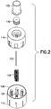
- FIG. 1 is a perspective view of an injection device 100 in accordance with an embodiment of the present invention and FIG. 2 is a perspective exploded view of the device 100.
- the injection device 100 includes a base 104 that has a proximal end 108 and a distal end 112, a sliding body slidably connected to the base 104, a double ended needle 120 fixed to the sliding body 116, and a biasing member 124 (such as a spring) for proximally biasing the sliding body 116 respect the base 104 and, as will be discussed in greater detail below, for retracting the needle 120 into the device 100 subsequent to activation thereof.
- a biasing member 124 such as a spring
- the device 100 also includes a medicament cartridge 128 for holding the medicament.
- the medicament cartridge 128 is slidably connected to the sliding body 116.
- the medicament cartridge 128 is made of glass.
- the medicament cartridge 128 is made of a transparent plastic material that does not react with the medicament. Examples of such a plastic material include, but are not limited to, cyclic olefin polymer (COP) and cyclic olefin copolymer (COC).
- COC cyclic olefin polymer
- BD CCP Resin cyclic olefin copolymer
- the device includes a stopper 132 slidably disposed within the medicament cartridge 128, for retaining the medicament within the medicament cartridge 128 and expelling the medicament from the medicament cartridge 128.
- the medicament cartridge 128 and the stopper 132 disposed therein define a medicament chamber therebetween.
- the stopper 132 is made of an elastomeric material, such as rubber, that does not react with the medicament.
- the medicament cartridge 128 is pre-assembled to the remainder of the device 100, and the entire device 100 is provided to the user in sterile packaging, for example a cup with a foil top.
- a pre-filled medicament cartridge 128 (including the stopper 132) is provided separately from the remainder of the device 100.
- the medicament cartridge 128 can be assembled to the remainder of the device 100 at the time of the injection, and thus, is, selectively connectable to the sliding body 116, as described in greater detail below.
- Refrigeration space may be at a premium in developing areas of the world. For medicament that needs to be refrigerated, such a design provides for more efficient use of the refrigeration space because only the medicament cartridge 128 is refrigerated, not the entire device 100.
- FIGS. 3 and 4 are respective perspective views of proximal and distal ends 108 and 112 of the base 104.
- the base 104 has a plurality of angled lips 136 disposed circumferentially about interior of the base 104. Each of the angled lips 136 projects radially inward, and is angled distally with respect to the base 104.
- each angled lip 136 has a proximal angled surface 140 and a distal angled surface 144.
- the base 104 also includes a plurality of axial ribs 148 circumferentially disposed about the interior of the base 104. The axial ribs 148 are distally separated from the angled lips 136 to define a locking space 152 therebetween.
- a pair of axial ribs 148 corresponds to each angled lip 136 and the individual ribs 148 of the pair are circumferentially disposed on opposing sides of the corresponding angled lip 136.
- the angled lips 136 and the axial ribs 148 (as well as the locking space 152 disposed therebetween) form a first locking mechanism, which is discussed in greater detail below.
- the base 104 additionally includes a central boss 156 with a central bore 160 through which the needle 120 moves.
- the base 104 includes a plurality of base locking ribs 158 for connecting the sliding body 116 and the base 104 prior to activation of the device 100.
- the distal end of the base 112 has a surface 164 for contacting a patient's skin.
- the surface 164 is flat.
- the surface 164 is concave, or proximally domed, for example, to stably contact the patient's skin.
- the surface 164 may be convex, have another shape, or have a plurality of shapes without departing from the scope of the invention.
- at least a portion of the surface 164 has an adhesive disposed thereon for temporarily adhering the device 100 to the patient's skin. Such an adhesive portion may be covered by, for example, a paper cover which is removed prior to use of the device 100.
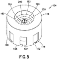
- FIG. 5 is a perspective view of proximal ends of the sliding body 116 and the needle 120
- FIG. 6 is a perspective view of the distal ends of the sliding body 116 and the needle 120.
- the needle 120 is fixed to the sliding body 116.
- the needle 120 does not displace relative to the sliding body 116.
- Methods for fixing the needle 120 to the sliding body 116 include gluing, epoxying, insert molding, and swaging, using, for example, heat or ultrasonic energy.
- heat or ultrasonic energy One skilled in the art will appreciate that other methods of fixing the needle 120 to the sliding body 116 may be employed without departing from the scope of the invention.
- the sliding body 116 includes a plurality of circumferentially disposed, distally depending, cantilevered legs 168.
- each leg 168 has a pair of feet 172 circumferentially protruding from a distal end thereof.
- proximal surfaces 176 of the feet 172 are angled to correspond to the angle of the distal angled surfaces 144 of the angled lips 136.
- the biasing member 124 is inserted into the base 104 around the central boss 156. Subsequently, the sliding body is inserted distally into the base 104 (over the biasing member 124) until the legs 168 and/or the feet 172 elastically deform radially inward and the feet 172 distally pass base locking ribs 158. Subsequently, the legs 168 and/or of the feet 172 spring back radially outward to contact the inner wall of the base 104.
- the base locking ribs 158 are angled to correspond to the angle of the proximal surfaces 176 of the feet 172.
- the base locking ribs 158 engage the proximal surfaces 176 of the feet 172 (due to the force of the biasing member 124, which biases the sliding body 116 proximally relative to the base 104) to prevent proximal movement of the feet 172 past the base locking ribs 158.
- Such an assembled state is shown, for example, in FIG. 7 .
- sliding body 116 additionally includes a central portion 180 that has a stopper-receiving boss 184 centrally disposed thereon.
- the walls of the central portion 180 form a cartridge channel for slidably receiving the medicament cartridge 128.
- the central portion 180 has an opening 188 at a distal end thereof for receiving the central boss 156 of the base 104 and the biasing member 124.
- the central portion 180 has a series of ribs disposed therein, specifically, a connecting rib 192, a holding rib 196, and a locking rib 200. As discussed in greater detail below, the locking rib 200 forms a second locking mechanism.
- the ribs 192, 196, and 200 interact with a cartridge lip 204, which protrudes radially outward from the distal end of the medicament cartridge 128.
- the ribs 192, 196, and 200 are annular.
- the connecting rib 192 for example, includes a plurality of connecting ribs 192 circumferentially spaced from each other about the central portion 180.
- the plurality of connecting ribs 192 are disposed to form a segmented array with spaces between the segments.
- Such an embodiment may reduce the amount of force necessary to distally advance the cartridge lip 204 past the connecting ribs 192.
- the medicament cartridge 128 is made of glass, and thus, is relatively inflexible, the reduced force required to advance the cartridge lip 204 past the plurality of discrete connecting ribs 192 may be advantageous.
- annular rings and ring segments may be respectively used for the ribs 192, 196, and 200 without departing from the scope of the invention.
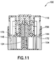
- a user inserts the medicament cartridge 128 into the central portion 180 of the sliding body 116 until the cartridge lip 204 passes the connecting rib 192 and comes to rest against the holding rib 196, as shown in FIG. 7 .
- the cartridge lip 204 is disposed between the connecting rib hundred 92 and the holding rib 196 and the feet 172 are disposed adjacent to the angled lips 136, as shown in FIGS. 7 .
- the sliding body 116 is in a first, or pre-activated position, in which the needle 120 is disposed entirely within the device 100.
- the force required to distally displace the cartridge lip 204 past the holding lip 196 is greater than the force required to distally displace the cartridge lip 204 past the connecting rib 192.
- Such an embodiment provides ease of connection of the medicament cartridge 128 with the sliding body 116 but prevents inadvertent activation of the device 100 during connection.
- the holding rib 196 protrudes radially inward further than the connecting rib 192 to provide the force differential.
- the holding rib 196 is less flexible than the connecting rib 192 to provide the force differential.
- the user presses the pre-activated device 100 ( FIG. 7 ) against the patient's skin 208 and presses down (i.e., distally) on the medicament cartridge 128.
- the force required to distally displace the cartridge lip 204 relative to the holding rib 196 is greater than the force required to distally displace the feet 172 relative to the angled lips 136.
- the force required to distally displace the cartridge lip 204 relative to the holding rib 196 is greater than the force required to compress the biasing member 124 and pierce the patient's skin 208 with the distal end of the needle 120. Accordingly, as shown in FIG. 8 , when the user presses down on the medicament cartridge 128, the force is transferred to the sliding body 116 and the legs 168 and/or the feet 172 elastically deform radially inward, thereby allowing the feet 172 to distally pass the angled lips 136. The legs 168 and/or the feet 172 then snap back radially outward and the slide distally along the axial ribs 148.
- the sliding body 116 compresses the biasing member 124 and drives the needle 120 to a predetermined depth into the patient's skin 208. In this second, or activated position of the sliding body 116, a portion of the needle 120 extends outside of the device 100.
- the cartridge lip 204 distally passes the holding rib 196 and the medicament cartridge 128 and the stopper travel distally in the cartridge channel, seating the stopper 132 on the stopper-receiving boss 184.
- This action also pierces the stopper 132 with the proximal end of the needle 120, thereby establishing fluid communication between the medicament and the needle 120, as shown in FIG. 9 .
- the stopper 132 is selectively pierceable by the needle 120 to establish communication with the medicament.
- the medicament cartridge 128 travels distally in the cartridge channel relative to the stopper 132 and the sliding body 116, thereby expelling the medicament from the medicament chamber, through the needle 120, and into the patient.
- the locking rib 200 is disposed at the distal end of the cartridge channel so that when the medicament cartridge 128 reaches the end of its distal stroke ( FIG. 10 ), the cartridge lip 204 distally passes the locking rib 200, thereby locking the medicament cartridge 128 relative to the sliding body 116. That is, the second locking mechanism (locking rib 200) engages the cartridge lip 204 and prevents movement of the medicament cartridge 128 with respect to the sliding body 116. Put another way, the second locking mechanism locks the medicament cartridge 128 relative to the sliding body 116 upon completion of the displacement of the medicament cartridge 128 relative to the sliding body 116. As used herein, locking an element relative to another element prevents subsequent relative displacement of the two elements. As additionally shown in FIG.
- the proximal surface of the medicament cartridge when the medicament cartridge 128 reaches the end of its distal stroke, is substantially planar with the proximal surface of the sliding body 116.
- Such a configuration prevents a user from gaining a purchase on the medicament cartridge 128, and thereby prevents an attempt to proximally displace the medicament cartridge 128 relative to the sliding body 116.
- the user releases the medicament cartridge 128 and the sliding body 116 (and the medicament cartridge 128 locked thereto) moves proximally with respect to the base 104 due to the force of the biasing member 124, thereby withdrawing the needle 120 from the patient and disposing the needle 120 completely within the device 100. More specifically, as the sliding body 116 moves proximally, the feet 172 slide proximally along the axial ribs 148.
- the legs 168 and/or the feet 172 Upon passing the proximal ends of the axial ribs 148, the legs 168 and/or the feet 172 spring back radially outward into the locking spaces 152 and the proximal surfaces 176 of the feet 172 engage the distal angled surfaces 144 of the angled lips 136, thereby locking the sliding body 116 relative to the base 104.
- the distal angled surface 144 prevents proximal movement of the feet 172 and the proximal ends of the axial ribs 148 prevent distal movement of the feet 172.
- the first locking mechanism and the locking feature interact to lock the sliding member 116 relative to the base 104 subsequent to retraction of the needle 120 into the device 100.
- the needle 120 is again retracted entirely within the device 100.
- the third position of the sliding body 116 is distally displaced relative to the first position.
Landscapes
- Health & Medical Sciences (AREA)
- Engineering & Computer Science (AREA)
- Animal Behavior & Ethology (AREA)
- General Health & Medical Sciences (AREA)
- Biomedical Technology (AREA)
- Heart & Thoracic Surgery (AREA)
- Hematology (AREA)
- Life Sciences & Earth Sciences (AREA)
- Vascular Medicine (AREA)
- Anesthesiology (AREA)
- Public Health (AREA)
- Veterinary Medicine (AREA)
- Environmental & Geological Engineering (AREA)
- Infusion, Injection, And Reservoir Apparatuses (AREA)
- Injection Moulding Of Plastics Or The Like (AREA)
- Chemical Or Physical Treatment Of Fibers (AREA)
- Polarising Elements (AREA)
Claims (10)
- Injektionsvorrichtung (100), die aufweist:eine Basis (104) mit einem proximalen Ende (108) und einer Fläche (164), die an einem distalen Ende (112) derselben angeordnet ist, um mit der Haut eines Patienten in Kontakt zu kommen, wobei die Basis einen ersten Verrastungsmechanismus, der aus einer Vielzahl von abgewinkelten Lippen (136) gebildet ist, und eine Vielzahl von axialen Rippen (148) aufweist, die am Umfang um das Innere der Basis (104) herum angeordnet sind;einen Gleitkörper (116), der koaxial gleitbar mit der Basis verbunden ist, wobei der Gleitkörper ein Verrastungsmerkmal (168, 172) und einen zweiten Verrastungsmechanismus (200) aufweist;eine doppelendige Nadel (120), die an dem Gleitkörper befestigt ist;ein Vorspannelement (124), das derart ausgebildet ist, dass es den Gleitkörper relativ zu der Basis proximal vorspannt, wodurch die Nadel im Anschluss an die Aktivierung der Vorrichtung in die Vorrichtung zurückgezogen wird;eine Medikamenten-Cartridge (128) zum Halten eines Medikaments, die koaxial gleitbar mit dem Gleitkörper verbunden ist, wobei die Medikamenten-Cartridge (128) ein zweites Verrastungsmerkmal (204) aufweist, wobei der zweite Verrastungsmechanismus und das zweite Verrastungsmerkmal derart ausgebildet sind, dass sie zusammenwirken, um bei Beendigung der Versetzung der Medikamenten-Cartridge relativ zu dem Gleitkörper die Medikamenten-Cartridge relativ zu dem Gleitkörper zu verrasten; undeinen Stopfen (132), der gleitbar in der Medikamenten-Cartridge angeordnet ist;wobei der erste Verrastungsmechanismus (136, 148, 152) und das Verrastungsmerkmal (168, 172) derart ausgebildet sind, dass sie zusammenwirken, um im Anschluss an das Zurückziehen der Nadel in die Vorrichtung den Gleitkörper relativ zu der Basis zu verrasten.
- Vorrichtung nach Anspruch 1, bei der der Gleitkörper aus einer ersten Position, in der die Nadel vollständig innerhalb der Vorrichtung angeordnet ist, in eine zweite Position, in der sich ein Abschnitt der Nadel von der Vorrichtung nach außen erstreckt, und in eine dritte Position, in der die Nadel vollständig in die Vorrichtung zurückgezogen ist, bewegbar ist, wobei die dritte Position relativ zur ersten Position distal versetzt ist.
- Vorrichtung nach Anspruch 1, bei der die Medikamenten-Cartridge mit dem Gleitkörper verbindbar ist und/oder bei der der Stopfen von der Nadel durchstechbar ist, um eine Kommunikation mit dem Medikament herzustellen.
- Vorrichtung nach Anspruch 1, bei der die abgewinkelten Lippen (136) radial nach innen vorstehen und distal abgewinkelt sind, wobei jede abgewinkelte Lippe eine proximale abgewinkelte Fläche (140) und eine distale abgewinkelte Fläche (144) aufweist; und
wobei die Rippen (148) distal von den abgewinkelten Lippen (136) getrennt sind, um einen Verrastungsraum (152) dazwischen zu definieren. - Vorrichtung nach Anspruch 4, bei der die Vielzahl von axialen Rippen (148) ein Paar von axialen Rippen aufweist, die jeweils einer abgewinkelten Lippe (136) entsprechen, wobei jedes Paar von axialen Rippen am Umfang auf gegenüberliegenden Seiten der entsprechenden abgewinkelten Lippe angeordnet ist.
- Vorrichtung nach Anspruch 4, bei der das Verrastungsmerkmal (168, 172) des Gleitkörpers eine Vielzahl von am Umfang angeordneten, distal herabhängenden, frei abstehenden Beinen (168) aufweist, wobei jedes Bein ein Paar von Füßen (172) aufweist, die am Umfang von einem distalen Ende desselben vorstehen, wobei jeweilige proximale Flächen der Füße vorzugsweise abgewinkelt sind, um dem Winkel der jeweiligen distalen abgewinkelten Flächen der abgewinkelten Lippen zu entsprechen.
- Vorrichtung nach Anspruch 6, bei der dann, wenn sich der Gleitkörper aus einer ersten Position, in der die Nadel vollständig innerhalb der Vorrichtung angeordnet ist, in eine zweite Position, in der sich ein Abschnitt der Nadel von der Vorrichtung nach außen erstreckt, bewegt, die Füße (172) an der proximalen abgewinkelten Fläche (140) der abgewinkelten Lippe (136) angreifen, wobei die Beine (168) radial nach innen ausgelenkt werden und die Beine radial nach außen vorgespannt werden, und sobald sich die Füße (172) distal an der abgewinkelten Lippe (136) vorbeibewegen, sich die Füße radial nach außen bewegen, um an den axialen Rippen (148) anzugreifen und diese entlang zu gleiten.
- Vorrichtung nach Anspruch 7, bei der dann, wenn sich der Gleitkörper aus der zweiten Position in die dritte Position bewegt, in der die Nadel vollständig in die Vorrichtung zurückgezogen ist, die Füße (172) die axialen Rippen (148) entlang gleiten, bis sie proximale Enden derselben erreichen, und sich dann radial nach außen in den Verrastungsraum (152) bewegen.
- Vorrichtung nach Anspruch 1, bei der:die Medikamenten-Cartridge eine Cartridge-Lippe (204) aufweist, die von einem distalen Ende derselben nach außen vorsteht; undder zweite Verrastungsmechanismus (200) des Gleitkörpers eine Verrastungsrippe (200) aufweist, die radial nach innen vorsteht, wobei die Verrastungsrippe angrenzend an ein distales Ende eines Cartridge-Kanals des Gleitkörpers angeordnet ist, in dem die Medikamenten-Cartridge läuft;wobei bei Beendigung der Versetzung der Medikamenten-Cartridge relativ zu dem Gleitkörper sich die Cartridge-Lippe distal an der Verrastungsrippe vorbeibewegt und die Verrastungsrippe die Medikamenten-Cartridge relativ zu dem Gleitkörper verrastet.
- Vorrichtung nach Anspruch 9, bei der der Cartridge-Kanal aufweist:eine Verbindungsrippe (192), die radial nach innen vorsteht; undeine Halterippe (196), die radial nach innen vorsteht und relativ zu der Verbindungsrippe distal angeordnet ist;wobei sich die Cartridge-Lippe (204) distal an der Verbindungsrippe (192) vorbeibewegt, um die Medikamenten-Cartridge mit dem Gleitkörper zu verbinden;wobei dann, wenn sich die Cartridge-Lippe (204) distal an der Halterippe (196) vorbeibewegt, die Nadel (120) den Stopfen (132) durchsticht; undwobei eine Kraft, die zum distalen Versetzen der Cartridge-Lippe (204) an der Halterippe (196) vorbei erforderlich ist, größer ist als eine Kraft, die zum distalen Versetzen der Cartridge-Lippe (204) an der Verbindungsrippe (192) vorbei erforderlich ist.
Applications Claiming Priority (1)
| Application Number | Priority Date | Filing Date | Title |
|---|---|---|---|
| PCT/US2011/000878 WO2012158136A1 (en) | 2011-05-18 | 2011-05-18 | Injection device |
Publications (3)
| Publication Number | Publication Date |
|---|---|
| EP2709696A1 EP2709696A1 (de) | 2014-03-26 |
| EP2709696A4 EP2709696A4 (de) | 2015-10-28 |
| EP2709696B1 true EP2709696B1 (de) | 2022-10-26 |
Family
ID=47177213
Family Applications (1)
| Application Number | Title | Priority Date | Filing Date |
|---|---|---|---|
| EP11865919.2A Active EP2709696B1 (de) | 2011-05-18 | 2011-05-18 | Injektionsvorrichtung |
Country Status (9)
| Country | Link |
|---|---|
| US (1) | US9844629B2 (de) |
| EP (1) | EP2709696B1 (de) |
| JP (1) | JP5897113B2 (de) |
| CN (2) | CN103619380B (de) |
| BR (1) | BR112013029629B1 (de) |
| CA (4) | CA3037365C (de) |
| ES (1) | ES2931328T3 (de) |
| MX (2) | MX339740B (de) |
| WO (1) | WO2012158136A1 (de) |
Families Citing this family (23)
| Publication number | Priority date | Publication date | Assignee | Title |
|---|---|---|---|---|
| JP2013523202A (ja) | 2010-03-25 | 2013-06-17 | ニュー インジェクション システムズ リミテッド | 注射器 |
| ES2675035T3 (es) | 2011-10-14 | 2018-07-05 | Amgen, Inc | Inyector y método de ensamblaje |
| US10471209B2 (en) | 2012-11-23 | 2019-11-12 | New Injection Systems Ltd. | Auto-injector assembly |
| IL292270B2 (en) | 2013-03-22 | 2024-04-01 | Amgen Inc | Injector and method of assembly |
| MX373358B (es) | 2013-10-24 | 2020-07-06 | Amgen Inc | Inyector y método de montaje. |
| EP3733147A1 (de) * | 2014-04-21 | 2020-11-04 | Becton Dickinson and Company Limited | Fluidtransfervorrichtung und verpackung dafür |
| US9415176B1 (en) | 2015-01-22 | 2016-08-16 | West Pharmaceutical Services, Inc. | Autoinjector having an end-of-dose visual indicator |
| CN107635527B (zh) * | 2015-03-10 | 2021-04-23 | 里珍纳龙药品有限公司 | 无菌刺穿系统和方法 |
| US11207465B2 (en) | 2015-06-04 | 2021-12-28 | West Pharma. Services Il. Ltd. | Cartridge insertion for drug delivery device |
| US9579453B1 (en) * | 2016-02-18 | 2017-02-28 | Chalbourne Brasington | Two-step auto-injection device |
| CN110536709A (zh) * | 2017-03-16 | 2019-12-03 | 诺瓦提斯公司 | 注射装置 |
| WO2019022950A1 (en) * | 2017-07-25 | 2019-01-31 | Amgen Inc. | DRUG DELIVERY DEVICE WITH CONTAINER ACCESS SYSTEM AND ASSEMBLY METHOD THEREOF |
| US10245381B2 (en) * | 2017-08-21 | 2019-04-02 | Chalbourne Brasington | Two-step auto-injection device |
| JP1629610S (de) * | 2017-10-25 | 2019-04-15 | ||
| JP7402799B2 (ja) | 2017-12-22 | 2023-12-21 | ウェスト ファーマ サービシーズ イスラエル リミテッド | サイズの異なるカートリッジを利用可能な注射器 |
| US12023463B2 (en) | 2018-01-02 | 2024-07-02 | Cerner Innovation, Inc. | Clinical notifications |
| US10357619B1 (en) | 2018-02-08 | 2019-07-23 | Chalbourne Brasington | Auto-injection device |
| JP7458140B2 (ja) * | 2018-02-09 | 2024-03-29 | ニプロ株式会社 | 薬液注入装置 |
| USD867588S1 (en) * | 2018-05-22 | 2019-11-19 | Sanofi | Cap of an injection device |
| EP3771460B1 (de) * | 2019-08-01 | 2022-10-12 | SCHOTT Schweiz AG | Dead-end behälter und behältersvorrichtung mit dead-end behälter |
| USD948715S1 (en) * | 2020-11-06 | 2022-04-12 | West Pharmaceutical Services, Inc. | Injection needle shield puller |
| WO2022207136A1 (en) * | 2021-03-31 | 2022-10-06 | Shl Medical Ag | Medicament delivery device |
| USD1007676S1 (en) | 2021-11-16 | 2023-12-12 | Regeneron Pharmaceuticals, Inc. | Wearable autoinjector |
Family Cites Families (41)
| Publication number | Priority date | Publication date | Assignee | Title |
|---|---|---|---|---|
| SU787035A1 (ru) * | 1978-01-11 | 1980-12-15 | Всесоюзный научно-исследовательский и испытательный институт медицинской техники | Устройство дл введени лекарственных препаратов |
| US4188950A (en) | 1978-10-30 | 1980-02-19 | Wardlaw Stephen C | Disposable syringe |
| US4227528A (en) | 1978-12-26 | 1980-10-14 | Wardlaw Stephen C | Automatic disposable hypodermic syringe |
| US4196732A (en) | 1978-12-26 | 1980-04-08 | Wardlaw Stephen C | Automatic disposable syringe and method of filling the same |
| US4258713A (en) | 1979-07-23 | 1981-03-31 | Wardlaw Stephen C | Automatic disposable hypodermic syringe |
| US4378015A (en) | 1981-12-21 | 1983-03-29 | Wardlaw Stephen C | Automatic injecting syringe |
| US4767413A (en) | 1987-04-20 | 1988-08-30 | Habley Medical Technology Corporation | Dental syringe having an automatically retractable needle |
| US4747831A (en) | 1987-04-29 | 1988-05-31 | Phase Medical, Inc. | Cannula insertion set with safety retracting needle |
| US4955871A (en) | 1987-04-29 | 1990-09-11 | Path | Single-use disposable syringe |
| US4850961A (en) | 1987-07-30 | 1989-07-25 | Wanderer Alan A | Indwelling placement device with guard |
| US4813426A (en) | 1987-11-09 | 1989-03-21 | Habley Medical Technology Corporation | Shielded safety syringe having a retractable needle |
| US4894054A (en) | 1988-06-20 | 1990-01-16 | Miskinyar Shir A | Preloaded automatic disposable syringe |
| US4900310A (en) | 1988-10-07 | 1990-02-13 | International Medication Systems Limited | Protective device for cannula used to draw blood |
| CA1337167C (en) | 1989-03-14 | 1995-10-03 | Eastman Kodak Company | Needle housing with retractable needle |
| US5019048A (en) | 1990-01-10 | 1991-05-28 | Margolin George D | Unit dose syringe with rotatable needle |
| ES2092572T3 (es) | 1990-07-04 | 1996-12-01 | Maxwell Edmund Whisson | Dispositivo parenteral mejorado. |
| US5248303A (en) | 1991-08-27 | 1993-09-28 | Margolin George D | Medical syringe with needle-retracting mechanism |
| CA2124073C (en) | 1991-11-20 | 2005-05-10 | Maxwell Edmund Whisson | Attachment for a parenteral device |
| US5267963A (en) | 1992-08-21 | 1993-12-07 | Nicholas Bachynsky | Medication injection device |
| DE69427226T2 (de) | 1993-03-24 | 2001-08-30 | Owen Mumford Ltd., Woodstock | Vorrichtung zur injektion |
| US5634906A (en) | 1995-12-27 | 1997-06-03 | Habley Medical Technology Corporation | Needle hiding shield for a dose metering syringe |
| BR9908839A (pt) | 1998-03-17 | 2001-10-02 | Mdc Invest Holdings Inc | Dispositivo médico |
| AU6414400A (en) | 1999-07-27 | 2001-02-13 | Pharma Consult Ges.M.B.H. | Device for automatically injecting injection liquids |
| CA2440886A1 (en) | 2001-03-15 | 2002-09-26 | Mdc Investment Holdings, Inc. | Retractable needle medical device for injecting fluid from a pre-filled cartridge |
| US6808507B2 (en) * | 2002-05-10 | 2004-10-26 | Cambridge Biostability Ltd. | Safety injectors |
| CN2589962Y (zh) * | 2002-12-31 | 2003-12-03 | 台杰生化科技股份有限公司 | 针座可自动回缩的液体注射/采取装置 |
| US7252651B2 (en) | 2003-01-07 | 2007-08-07 | Becton, Dickinson And Company | Disposable injection device |
| DE602004013140T2 (de) | 2003-05-08 | 2009-07-02 | Novo Nordisk A/S | Interne nadeleinführvorrichtung |
| US8932264B2 (en) * | 2003-08-11 | 2015-01-13 | Becton, Dickinson And Company | Medication delivery pen assembly with needle locking safety shield |
| DE602005003009T2 (de) | 2004-01-23 | 2008-08-14 | The Medical House Plc, Attercliffe | Injektionsvorrichtung |
| GB2410188B (en) * | 2004-01-23 | 2006-01-25 | Medical House Plc | Injection device |
| US7670314B2 (en) * | 2004-02-17 | 2010-03-02 | Children's Hospital Medical Center | Injection device for administering a vaccine |
| US7621891B2 (en) | 2004-12-06 | 2009-11-24 | Washington Biotech Corporation | Method and apparatus for delivering epinephrine |
| CA2536845C (en) * | 2006-02-16 | 2009-10-27 | Pka Softtouch Corp. | Drug delivery device |
| NZ595031A (en) * | 2007-07-02 | 2012-02-24 | Unitract Syringe Pty Ltd | Automatically retracting syringe with spring based mechanisim |
| CN101912648B (zh) * | 2008-01-23 | 2013-04-24 | 诺沃-诺迪斯克有限公司 | 用于注射所分配剂量的液体药物的设备 |
| WO2010035056A1 (en) * | 2008-09-29 | 2010-04-01 | Becton Dickinson France | Automatic injection device with sensitive indicator of completed injection |
| GB2467904B (en) | 2009-02-17 | 2013-06-12 | Oval Medical Technologies Ltd | Drug container and delivery mechanism |
| GB2471304B (en) | 2009-06-24 | 2013-12-11 | Oval Medical Technologies Ltd | A pre-filled syringe or autoinjector |
| WO2011117287A1 (en) * | 2010-03-25 | 2011-09-29 | Sanofi-Aventis Deutschland Gmbh | Medicated module with automatic reservoir engagement |
| JP5657786B2 (ja) | 2010-05-26 | 2015-01-21 | ベクトン・ディキンソン・アンド・カンパニーBecton, Dickinson And Company | 安全針アセンブリ |
-
2011
- 2011-05-18 MX MX2013013314A patent/MX339740B/es active IP Right Grant
- 2011-05-18 ES ES11865919T patent/ES2931328T3/es active Active
- 2011-05-18 BR BR112013029629-1A patent/BR112013029629B1/pt active IP Right Grant
- 2011-05-18 JP JP2014511326A patent/JP5897113B2/ja active Active
- 2011-05-18 CA CA3037365A patent/CA3037365C/en active Active
- 2011-05-18 EP EP11865919.2A patent/EP2709696B1/de active Active
- 2011-05-18 CA CA3037381A patent/CA3037381C/en active Active
- 2011-05-18 CA CA2836234A patent/CA2836234C/en active Active
- 2011-05-18 US US14/117,838 patent/US9844629B2/en active Active
- 2011-05-18 MX MX2016001114A patent/MX349581B/es unknown
- 2011-05-18 WO PCT/US2011/000878 patent/WO2012158136A1/en not_active Ceased
- 2011-05-18 CN CN201180071886.3A patent/CN103619380B/zh active Active
- 2011-05-18 CA CA3037363A patent/CA3037363C/en active Active
- 2011-05-18 CN CN201710147808.6A patent/CN106860975B/zh active Active
Also Published As
| Publication number | Publication date |
|---|---|
| CA3037363A1 (en) | 2012-11-22 |
| US9844629B2 (en) | 2017-12-19 |
| CA3037365A1 (en) | 2012-11-22 |
| WO2012158136A1 (en) | 2012-11-22 |
| MX2013013314A (es) | 2014-05-27 |
| CA3037363C (en) | 2021-04-13 |
| CA3037381A1 (en) | 2012-11-22 |
| JP5897113B2 (ja) | 2016-03-30 |
| CA3037365C (en) | 2021-04-13 |
| BR112013029629B1 (pt) | 2021-08-31 |
| ES2931328T3 (es) | 2022-12-28 |
| MX349581B (es) | 2017-08-04 |
| JP2014516688A (ja) | 2014-07-17 |
| BR112013029629A2 (pt) | 2020-10-06 |
| CA3037381C (en) | 2020-07-21 |
| CN103619380B (zh) | 2017-04-05 |
| EP2709696A4 (de) | 2015-10-28 |
| US20140081239A1 (en) | 2014-03-20 |
| CN106860975A (zh) | 2017-06-20 |
| MX339740B (es) | 2016-06-07 |
| CN103619380A (zh) | 2014-03-05 |
| CA2836234A1 (en) | 2012-11-22 |
| CN106860975B (zh) | 2019-12-31 |
| CA2836234C (en) | 2020-06-09 |
| EP2709696A1 (de) | 2014-03-26 |
Similar Documents
| Publication | Publication Date | Title |
|---|---|---|
| EP2709696B1 (de) | Injektionsvorrichtung | |
| CA2978588C (en) | Single-use injector of low cost | |
| CN105561443B (zh) | 可伸缩针式注射器 | |
| CN104582767A (zh) | 回缩针安全性注射器 | |
| EP2695630A1 (de) | Flüssigkeitsinfusionsinstrument | |
| KR20140042901A (ko) | 주사 장치용 재충전 모듈 | |
| EP2560704B1 (de) | Automatische injektionsspritzenanordung mit integriertem füllbarem medizinischem behälter und verfahren zur befüllung einer injektionsspritzenanordnung | |
| CN117500544A (zh) | 用于注射装置的组件 |
Legal Events
| Date | Code | Title | Description |
|---|---|---|---|
| PUAI | Public reference made under article 153(3) epc to a published international application that has entered the european phase |
Free format text: ORIGINAL CODE: 0009012 |
|
| 17P | Request for examination filed |
Effective date: 20131119 |
|
| AK | Designated contracting states |
Kind code of ref document: A1 Designated state(s): AL AT BE BG CH CY CZ DE DK EE ES FI FR GB GR HR HU IE IS IT LI LT LU LV MC MK MT NL NO PL PT RO RS SE SI SK SM TR |
|
| DAX | Request for extension of the european patent (deleted) | ||
| RA4 | Supplementary search report drawn up and despatched (corrected) |
Effective date: 20150924 |
|
| RIC1 | Information provided on ipc code assigned before grant |
Ipc: A61M 5/20 20060101AFI20150918BHEP Ipc: A61M 5/32 20060101ALI20150918BHEP Ipc: A61M 5/24 20060101ALI20150918BHEP |
|
| RAP1 | Party data changed (applicant data changed or rights of an application transferred) |
Owner name: BECTON, DICKINSON AND COMPANY |
|
| STAA | Information on the status of an ep patent application or granted ep patent |
Free format text: STATUS: EXAMINATION IS IN PROGRESS |
|
| 17Q | First examination report despatched |
Effective date: 20180424 |
|
| GRAP | Despatch of communication of intention to grant a patent |
Free format text: ORIGINAL CODE: EPIDOSNIGR1 |
|
| STAA | Information on the status of an ep patent application or granted ep patent |
Free format text: STATUS: GRANT OF PATENT IS INTENDED |
|
| INTG | Intention to grant announced |
Effective date: 20211116 |
|
| GRAJ | Information related to disapproval of communication of intention to grant by the applicant or resumption of examination proceedings by the epo deleted |
Free format text: ORIGINAL CODE: EPIDOSDIGR1 |
|
| STAA | Information on the status of an ep patent application or granted ep patent |
Free format text: STATUS: EXAMINATION IS IN PROGRESS |
|
| INTC | Intention to grant announced (deleted) | ||
| GRAP | Despatch of communication of intention to grant a patent |
Free format text: ORIGINAL CODE: EPIDOSNIGR1 |
|
| STAA | Information on the status of an ep patent application or granted ep patent |
Free format text: STATUS: GRANT OF PATENT IS INTENDED |
|
| INTG | Intention to grant announced |
Effective date: 20220531 |
|
| GRAS | Grant fee paid |
Free format text: ORIGINAL CODE: EPIDOSNIGR3 |
|
| GRAA | (expected) grant |
Free format text: ORIGINAL CODE: 0009210 |
|
| STAA | Information on the status of an ep patent application or granted ep patent |
Free format text: STATUS: THE PATENT HAS BEEN GRANTED |
|
| AK | Designated contracting states |
Kind code of ref document: B1 Designated state(s): AL AT BE BG CH CY CZ DE DK EE ES FI FR GB GR HR HU IE IS IT LI LT LU LV MC MK MT NL NO PL PT RO RS SE SI SK SM TR |
|
| REG | Reference to a national code |
Ref country code: GB Ref legal event code: FG4D |
|
| REG | Reference to a national code |
Ref country code: CH Ref legal event code: EP |
|
| REG | Reference to a national code |
Ref country code: AT Ref legal event code: REF Ref document number: 1526597 Country of ref document: AT Kind code of ref document: T Effective date: 20221115 |
|
| REG | Reference to a national code |
Ref country code: DE Ref legal event code: R096 Ref document number: 602011073401 Country of ref document: DE |
|
| REG | Reference to a national code |
Ref country code: IE Ref legal event code: FG4D |
|
| REG | Reference to a national code |
Ref country code: ES Ref legal event code: FG2A Ref document number: 2931328 Country of ref document: ES Kind code of ref document: T3 Effective date: 20221228 |
|
| REG | Reference to a national code |
Ref country code: LT Ref legal event code: MG9D |
|
| REG | Reference to a national code |
Ref country code: NL Ref legal event code: MP Effective date: 20221026 |
|
| REG | Reference to a national code |
Ref country code: AT Ref legal event code: MK05 Ref document number: 1526597 Country of ref document: AT Kind code of ref document: T Effective date: 20221026 |
|
| PG25 | Lapsed in a contracting state [announced via postgrant information from national office to epo] |
Ref country code: NL Free format text: LAPSE BECAUSE OF FAILURE TO SUBMIT A TRANSLATION OF THE DESCRIPTION OR TO PAY THE FEE WITHIN THE PRESCRIBED TIME-LIMIT Effective date: 20221026 |
|
| PG25 | Lapsed in a contracting state [announced via postgrant information from national office to epo] |
Ref country code: SE Free format text: LAPSE BECAUSE OF FAILURE TO SUBMIT A TRANSLATION OF THE DESCRIPTION OR TO PAY THE FEE WITHIN THE PRESCRIBED TIME-LIMIT Effective date: 20221026 Ref country code: PT Free format text: LAPSE BECAUSE OF FAILURE TO SUBMIT A TRANSLATION OF THE DESCRIPTION OR TO PAY THE FEE WITHIN THE PRESCRIBED TIME-LIMIT Effective date: 20230227 Ref country code: NO Free format text: LAPSE BECAUSE OF FAILURE TO SUBMIT A TRANSLATION OF THE DESCRIPTION OR TO PAY THE FEE WITHIN THE PRESCRIBED TIME-LIMIT Effective date: 20230126 Ref country code: LT Free format text: LAPSE BECAUSE OF FAILURE TO SUBMIT A TRANSLATION OF THE DESCRIPTION OR TO PAY THE FEE WITHIN THE PRESCRIBED TIME-LIMIT Effective date: 20221026 Ref country code: FI Free format text: LAPSE BECAUSE OF FAILURE TO SUBMIT A TRANSLATION OF THE DESCRIPTION OR TO PAY THE FEE WITHIN THE PRESCRIBED TIME-LIMIT Effective date: 20221026 Ref country code: AT Free format text: LAPSE BECAUSE OF FAILURE TO SUBMIT A TRANSLATION OF THE DESCRIPTION OR TO PAY THE FEE WITHIN THE PRESCRIBED TIME-LIMIT Effective date: 20221026 |
|
| PG25 | Lapsed in a contracting state [announced via postgrant information from national office to epo] |
Ref country code: RS Free format text: LAPSE BECAUSE OF FAILURE TO SUBMIT A TRANSLATION OF THE DESCRIPTION OR TO PAY THE FEE WITHIN THE PRESCRIBED TIME-LIMIT Effective date: 20221026 Ref country code: PL Free format text: LAPSE BECAUSE OF FAILURE TO SUBMIT A TRANSLATION OF THE DESCRIPTION OR TO PAY THE FEE WITHIN THE PRESCRIBED TIME-LIMIT Effective date: 20221026 Ref country code: LV Free format text: LAPSE BECAUSE OF FAILURE TO SUBMIT A TRANSLATION OF THE DESCRIPTION OR TO PAY THE FEE WITHIN THE PRESCRIBED TIME-LIMIT Effective date: 20221026 Ref country code: IS Free format text: LAPSE BECAUSE OF FAILURE TO SUBMIT A TRANSLATION OF THE DESCRIPTION OR TO PAY THE FEE WITHIN THE PRESCRIBED TIME-LIMIT Effective date: 20230226 Ref country code: HR Free format text: LAPSE BECAUSE OF FAILURE TO SUBMIT A TRANSLATION OF THE DESCRIPTION OR TO PAY THE FEE WITHIN THE PRESCRIBED TIME-LIMIT Effective date: 20221026 Ref country code: GR Free format text: LAPSE BECAUSE OF FAILURE TO SUBMIT A TRANSLATION OF THE DESCRIPTION OR TO PAY THE FEE WITHIN THE PRESCRIBED TIME-LIMIT Effective date: 20230127 |
|
| REG | Reference to a national code |
Ref country code: DE Ref legal event code: R097 Ref document number: 602011073401 Country of ref document: DE |
|
| PG25 | Lapsed in a contracting state [announced via postgrant information from national office to epo] |
Ref country code: SM Free format text: LAPSE BECAUSE OF FAILURE TO SUBMIT A TRANSLATION OF THE DESCRIPTION OR TO PAY THE FEE WITHIN THE PRESCRIBED TIME-LIMIT Effective date: 20221026 Ref country code: RO Free format text: LAPSE BECAUSE OF FAILURE TO SUBMIT A TRANSLATION OF THE DESCRIPTION OR TO PAY THE FEE WITHIN THE PRESCRIBED TIME-LIMIT Effective date: 20221026 Ref country code: EE Free format text: LAPSE BECAUSE OF FAILURE TO SUBMIT A TRANSLATION OF THE DESCRIPTION OR TO PAY THE FEE WITHIN THE PRESCRIBED TIME-LIMIT Effective date: 20221026 Ref country code: DK Free format text: LAPSE BECAUSE OF FAILURE TO SUBMIT A TRANSLATION OF THE DESCRIPTION OR TO PAY THE FEE WITHIN THE PRESCRIBED TIME-LIMIT Effective date: 20221026 Ref country code: CZ Free format text: LAPSE BECAUSE OF FAILURE TO SUBMIT A TRANSLATION OF THE DESCRIPTION OR TO PAY THE FEE WITHIN THE PRESCRIBED TIME-LIMIT Effective date: 20221026 |
|
| PG25 | Lapsed in a contracting state [announced via postgrant information from national office to epo] |
Ref country code: SK Free format text: LAPSE BECAUSE OF FAILURE TO SUBMIT A TRANSLATION OF THE DESCRIPTION OR TO PAY THE FEE WITHIN THE PRESCRIBED TIME-LIMIT Effective date: 20221026 Ref country code: AL Free format text: LAPSE BECAUSE OF FAILURE TO SUBMIT A TRANSLATION OF THE DESCRIPTION OR TO PAY THE FEE WITHIN THE PRESCRIBED TIME-LIMIT Effective date: 20221026 |
|
| PLBE | No opposition filed within time limit |
Free format text: ORIGINAL CODE: 0009261 |
|
| STAA | Information on the status of an ep patent application or granted ep patent |
Free format text: STATUS: NO OPPOSITION FILED WITHIN TIME LIMIT |
|
| 26N | No opposition filed |
Effective date: 20230727 |
|
| PG25 | Lapsed in a contracting state [announced via postgrant information from national office to epo] |
Ref country code: SI Free format text: LAPSE BECAUSE OF FAILURE TO SUBMIT A TRANSLATION OF THE DESCRIPTION OR TO PAY THE FEE WITHIN THE PRESCRIBED TIME-LIMIT Effective date: 20221026 |
|
| REG | Reference to a national code |
Ref country code: CH Ref legal event code: PL |
|
| PG25 | Lapsed in a contracting state [announced via postgrant information from national office to epo] |
Ref country code: MC Free format text: LAPSE BECAUSE OF FAILURE TO SUBMIT A TRANSLATION OF THE DESCRIPTION OR TO PAY THE FEE WITHIN THE PRESCRIBED TIME-LIMIT Effective date: 20221026 |
|
| REG | Reference to a national code |
Ref country code: BE Ref legal event code: MM Effective date: 20230531 |
|
| PG25 | Lapsed in a contracting state [announced via postgrant information from national office to epo] |
Ref country code: MC Free format text: LAPSE BECAUSE OF FAILURE TO SUBMIT A TRANSLATION OF THE DESCRIPTION OR TO PAY THE FEE WITHIN THE PRESCRIBED TIME-LIMIT Effective date: 20221026 Ref country code: LU Free format text: LAPSE BECAUSE OF NON-PAYMENT OF DUE FEES Effective date: 20230518 Ref country code: LI Free format text: LAPSE BECAUSE OF NON-PAYMENT OF DUE FEES Effective date: 20230531 Ref country code: CH Free format text: LAPSE BECAUSE OF NON-PAYMENT OF DUE FEES Effective date: 20230531 |
|
| REG | Reference to a national code |
Ref country code: IE Ref legal event code: MM4A |
|
| PG25 | Lapsed in a contracting state [announced via postgrant information from national office to epo] |
Ref country code: IE Free format text: LAPSE BECAUSE OF NON-PAYMENT OF DUE FEES Effective date: 20230518 |
|
| PG25 | Lapsed in a contracting state [announced via postgrant information from national office to epo] |
Ref country code: IE Free format text: LAPSE BECAUSE OF NON-PAYMENT OF DUE FEES Effective date: 20230518 |
|
| PG25 | Lapsed in a contracting state [announced via postgrant information from national office to epo] |
Ref country code: BE Free format text: LAPSE BECAUSE OF NON-PAYMENT OF DUE FEES Effective date: 20230531 |
|
| PG25 | Lapsed in a contracting state [announced via postgrant information from national office to epo] |
Ref country code: BG Free format text: LAPSE BECAUSE OF FAILURE TO SUBMIT A TRANSLATION OF THE DESCRIPTION OR TO PAY THE FEE WITHIN THE PRESCRIBED TIME-LIMIT Effective date: 20221026 |
|
| PG25 | Lapsed in a contracting state [announced via postgrant information from national office to epo] |
Ref country code: BG Free format text: LAPSE BECAUSE OF FAILURE TO SUBMIT A TRANSLATION OF THE DESCRIPTION OR TO PAY THE FEE WITHIN THE PRESCRIBED TIME-LIMIT Effective date: 20221026 |
|
| PGFP | Annual fee paid to national office [announced via postgrant information from national office to epo] |
Ref country code: DE Payment date: 20250423 Year of fee payment: 15 |
|
| PGFP | Annual fee paid to national office [announced via postgrant information from national office to epo] |
Ref country code: GB Payment date: 20250423 Year of fee payment: 15 Ref country code: ES Payment date: 20250602 Year of fee payment: 15 |
|
| PGFP | Annual fee paid to national office [announced via postgrant information from national office to epo] |
Ref country code: IT Payment date: 20250423 Year of fee payment: 15 |
|
| PGFP | Annual fee paid to national office [announced via postgrant information from national office to epo] |
Ref country code: FR Payment date: 20250423 Year of fee payment: 15 |
|
| PG25 | Lapsed in a contracting state [announced via postgrant information from national office to epo] |
Ref country code: CY Free format text: LAPSE BECAUSE OF FAILURE TO SUBMIT A TRANSLATION OF THE DESCRIPTION OR TO PAY THE FEE WITHIN THE PRESCRIBED TIME-LIMIT; INVALID AB INITIO Effective date: 20110518 |
|
| PG25 | Lapsed in a contracting state [announced via postgrant information from national office to epo] |
Ref country code: HU Free format text: LAPSE BECAUSE OF FAILURE TO SUBMIT A TRANSLATION OF THE DESCRIPTION OR TO PAY THE FEE WITHIN THE PRESCRIBED TIME-LIMIT; INVALID AB INITIO Effective date: 20110518 |
|
| PG25 | Lapsed in a contracting state [announced via postgrant information from national office to epo] |
Ref country code: TR Free format text: LAPSE BECAUSE OF FAILURE TO SUBMIT A TRANSLATION OF THE DESCRIPTION OR TO PAY THE FEE WITHIN THE PRESCRIBED TIME-LIMIT Effective date: 20221026 |