EP2709704B1 - Katheter mit heilungsdummy - Google Patents
Katheter mit heilungsdummy Download PDFInfo
- Publication number
- EP2709704B1 EP2709704B1 EP12721537.4A EP12721537A EP2709704B1 EP 2709704 B1 EP2709704 B1 EP 2709704B1 EP 12721537 A EP12721537 A EP 12721537A EP 2709704 B1 EP2709704 B1 EP 2709704B1
- Authority
- EP
- European Patent Office
- Prior art keywords
- catheter
- healing
- dummy
- tubing
- tissue
- Prior art date
- Legal status (The legal status is an assumption and is not a legal conclusion. Google has not performed a legal analysis and makes no representation as to the accuracy of the status listed.)
- Active
Links
Images


Classifications
-
- A—HUMAN NECESSITIES
- A61—MEDICAL OR VETERINARY SCIENCE; HYGIENE
- A61M—DEVICES FOR INTRODUCING MEDIA INTO, OR ONTO, THE BODY; DEVICES FOR TRANSDUCING BODY MEDIA OR FOR TAKING MEDIA FROM THE BODY; DEVICES FOR PRODUCING OR ENDING SLEEP OR STUPOR
- A61M5/00—Devices for bringing media into the body in a subcutaneous, intra-vascular or intramuscular way; Accessories therefor, e.g. filling or cleaning devices, arm-rests
- A61M5/14—Infusion devices, e.g. infusing by gravity; Blood infusion; Accessories therefor
- A61M5/142—Pressure infusion, e.g. using pumps
- A61M5/14244—Pressure infusion, e.g. using pumps adapted to be carried by the patient, e.g. portable on the body
- A61M5/14276—Pressure infusion, e.g. using pumps adapted to be carried by the patient, e.g. portable on the body specially adapted for implantation
-
- A—HUMAN NECESSITIES
- A61—MEDICAL OR VETERINARY SCIENCE; HYGIENE
- A61B—DIAGNOSIS; SURGERY; IDENTIFICATION
- A61B5/00—Measuring for diagnostic purposes; Identification of persons
- A61B5/145—Measuring characteristics of blood in vivo, e.g. gas concentration or pH-value ; Measuring characteristics of body fluids or tissues, e.g. interstitial fluid or cerebral tissue
- A61B5/14507—Measuring characteristics of blood in vivo, e.g. gas concentration or pH-value ; Measuring characteristics of body fluids or tissues, e.g. interstitial fluid or cerebral tissue specially adapted for measuring characteristics of body fluids other than blood
-
- A—HUMAN NECESSITIES
- A61—MEDICAL OR VETERINARY SCIENCE; HYGIENE
- A61B—DIAGNOSIS; SURGERY; IDENTIFICATION
- A61B5/00—Measuring for diagnostic purposes; Identification of persons
- A61B5/145—Measuring characteristics of blood in vivo, e.g. gas concentration or pH-value ; Measuring characteristics of body fluids or tissues, e.g. interstitial fluid or cerebral tissue
- A61B5/14525—Measuring characteristics of blood in vivo, e.g. gas concentration or pH-value ; Measuring characteristics of body fluids or tissues, e.g. interstitial fluid or cerebral tissue using microdialysis
-
- A—HUMAN NECESSITIES
- A61—MEDICAL OR VETERINARY SCIENCE; HYGIENE
- A61B—DIAGNOSIS; SURGERY; IDENTIFICATION
- A61B5/00—Measuring for diagnostic purposes; Identification of persons
- A61B5/145—Measuring characteristics of blood in vivo, e.g. gas concentration or pH-value ; Measuring characteristics of body fluids or tissues, e.g. interstitial fluid or cerebral tissue
- A61B5/14532—Measuring characteristics of blood in vivo, e.g. gas concentration or pH-value ; Measuring characteristics of body fluids or tissues, e.g. interstitial fluid or cerebral tissue for measuring glucose, e.g. by tissue impedance measurement
-
- A—HUMAN NECESSITIES
- A61—MEDICAL OR VETERINARY SCIENCE; HYGIENE
- A61M—DEVICES FOR INTRODUCING MEDIA INTO, OR ONTO, THE BODY; DEVICES FOR TRANSDUCING BODY MEDIA OR FOR TAKING MEDIA FROM THE BODY; DEVICES FOR PRODUCING OR ENDING SLEEP OR STUPOR
- A61M1/00—Suction or pumping devices for medical purposes; Devices for carrying-off, for treatment of, or for carrying-over, body-liquids; Drainage systems
- A61M1/84—Drainage tubes; Aspiration tips
- A61M1/85—Drainage tubes; Aspiration tips with gas or fluid supply means, e.g. for supplying rinsing fluids or anticoagulants
-
- A—HUMAN NECESSITIES
- A61—MEDICAL OR VETERINARY SCIENCE; HYGIENE
- A61M—DEVICES FOR INTRODUCING MEDIA INTO, OR ONTO, THE BODY; DEVICES FOR TRANSDUCING BODY MEDIA OR FOR TAKING MEDIA FROM THE BODY; DEVICES FOR PRODUCING OR ENDING SLEEP OR STUPOR
- A61M25/00—Catheters; Hollow probes
- A61M25/0017—Catheters; Hollow probes specially adapted for long-term hygiene care, e.g. urethral or indwelling catheters to prevent infections
-
- A—HUMAN NECESSITIES
- A61—MEDICAL OR VETERINARY SCIENCE; HYGIENE
- A61M—DEVICES FOR INTRODUCING MEDIA INTO, OR ONTO, THE BODY; DEVICES FOR TRANSDUCING BODY MEDIA OR FOR TAKING MEDIA FROM THE BODY; DEVICES FOR PRODUCING OR ENDING SLEEP OR STUPOR
- A61M39/00—Tubes, tube connectors, tube couplings, valves, access sites or the like, specially adapted for medical use
- A61M39/02—Access sites
-
- A—HUMAN NECESSITIES
- A61—MEDICAL OR VETERINARY SCIENCE; HYGIENE
- A61M—DEVICES FOR INTRODUCING MEDIA INTO, OR ONTO, THE BODY; DEVICES FOR TRANSDUCING BODY MEDIA OR FOR TAKING MEDIA FROM THE BODY; DEVICES FOR PRODUCING OR ENDING SLEEP OR STUPOR
- A61M25/00—Catheters; Hollow probes
- A61M2025/0018—Catheters; Hollow probes having a plug, e.g. an inflatable plug for closing catheter lumens
-
- A—HUMAN NECESSITIES
- A61—MEDICAL OR VETERINARY SCIENCE; HYGIENE
- A61M—DEVICES FOR INTRODUCING MEDIA INTO, OR ONTO, THE BODY; DEVICES FOR TRANSDUCING BODY MEDIA OR FOR TAKING MEDIA FROM THE BODY; DEVICES FOR PRODUCING OR ENDING SLEEP OR STUPOR
- A61M39/00—Tubes, tube connectors, tube couplings, valves, access sites or the like, specially adapted for medical use
- A61M39/02—Access sites
- A61M39/0247—Semi-permanent or permanent transcutaneous or percutaneous access sites to the inside of the body
- A61M2039/025—Semi-permanent or permanent transcutaneous or percutaneous access sites to the inside of the body through bones or teeth, e.g. through the skull
-
- A—HUMAN NECESSITIES
- A61—MEDICAL OR VETERINARY SCIENCE; HYGIENE
- A61M—DEVICES FOR INTRODUCING MEDIA INTO, OR ONTO, THE BODY; DEVICES FOR TRANSDUCING BODY MEDIA OR FOR TAKING MEDIA FROM THE BODY; DEVICES FOR PRODUCING OR ENDING SLEEP OR STUPOR
- A61M39/00—Tubes, tube connectors, tube couplings, valves, access sites or the like, specially adapted for medical use
- A61M39/02—Access sites
- A61M39/0247—Semi-permanent or permanent transcutaneous or percutaneous access sites to the inside of the body
- A61M2039/0273—Semi-permanent or permanent transcutaneous or percutaneous access sites to the inside of the body for introducing catheters into the body
Definitions
- the invention relates to a catheter for implantation into a tissue.
- the invention relates to a medical system.
- a needle-like catheter in order to capture the alterations or levels of biochemical entities at tissue level in vivo for instance blood glucose levels subcutaneously, a needle-like catheter may be inserted into tissue, for instance in adipose tissue, muscle tissue, or skin.
- Linear catheters with a single lumen and an exchange area can be used to establish flow-through path for perfusion fluid.
- a perfusion fluid is continuously infused through the inner lumen and withdrawn through the annular space between the inner cannula and the outer catheter tubing.
- the perfusate is enriched by surrounding substances (or solutes, entities, molecules), such that the substances can be detected in the outflow.
- substances or solutes, entities, molecules
- a glucose sensor outside the body can capture glucose from the aspirated fluid.
- the fluid in the outflow is not a dialysate resulting from a membrane process, but to keep the analogy between microdialysis and microperfusion the term "dialysate" herein may also mean microperfusion outflows fluids.
- cerebral OFM is rendered difficult when using conventional approaches.
- the so-called blood-brain barrier When implanting a cerebral catheter, the so-called blood-brain barrier can be disturbed or even disabled by the injury of the brain being caused by the implantation.
- the intact blood-brain barrier provides for a separation of circulating blood and cerebral extracellular fluid in the central nervous system. Endothelial cells restrict the diffusion of microscopic objects (for instance bacteria) and large or hydrophilic molecules into the central nervous system, while allowing the diffusion of small hydrophobic molecules (O 2 , CO 2 , neuroactive drugs,).
- cerebral catheters are specifically delicate, different types of catheters suffer from problems arising from the risk of injury during implantation or removal.
- WO 2002/056937 discloses a system for delivering substances or apparatus to an extravascular target site within the body of a human or veterinary patient, said system comprising a vessel wall penetrating catheter that comprises a catheter body that is insertable into the vasculature of the patient and a vessel wall penetrating member having a lumen extending longitudinally therethrough, said penetrating member being passable from the catheter body and through the wall of a blood vessel in which the catheter body is positioned, and a delivery catheter having a lumen extending longitudinally therethrough, said delivery catheter being advanceable through the lumen of the vessel wall penetrating member to an extravascular target site, said vessel wall penetrating member being retractable into the catheter body of the vessel wall penetrating catheter and the vessel wall penetrating catheter being removable from the patient's body such that the delivery catheter remains indwelling with the distal end of the delivery catheter located at the extravascular target site.
- WO 2004/096314 discloses a catheter assembly for intracranial treatment of a patient, wherein the assembly comprises an outer catheter and an inner catheter.
- the outer catheter includes a proximal opening, at least one aperture, a lumen connecting the opening and the aperture, and at least one element.
- the inner catheter is adapted to be received within the lumen and includes a passageway and at least one port for transferring fluids between the inner catheter and a tissue region within the patient's brain.
- the assembly facilitates regular accurate placement of the drug delivery catheter at the tissue region without additional extended contact with the brain during insertion.
- WO 2007/138590 discloses an implantable pump for pumping a drug in a patient's body.
- the pump includes a drug delivery chamber configured to be filled with the drug and a drug delivery catheter having a catheter lumen and a distal end, the drug delivery catheter in fluid communication with the drug delivery chamber and configured to deliver the drug to a delivery site. It also includes a pushing element coupled to the distal end of the catheter, and configured to push away from the catheter lumen fibrotic matter that has developed in response to the drug delivery catheter.
- US 2006/235349 discloses cerebrospinal fluid shunts (implantable devices for diversion of excess fluid from the brain to other body cavities) used to treat hydrocephalus often malfunction.
- a common etiology of shunt malfunction is obstruction of the distal catheter tip by accumulating particulate matter such as fat or proteinaceous debris.
- the proposed implantable device maintains the patency of the cerebrospinal fluid shunt with mechanical energy which serves to "scrub" the catheter lumen of particulate debris.
- the device accomplishes this by housing a source of mechanical energy which is coupled to the external aspect of the catheter, itself traversing through a bore in the device.
- the energy source secondarily induces a waveform in the cerebrospinal fluid flowing through the catheter.
- the fluid waveform exerts shearing forces on the catheter wall and serves to disrupt the formation and accumulation of debris that potentially could occlude the shunt catheter, thereby maintaining patency of the shunt.
- US-2008/0119789 discloses a therapy delivery system for the intermittent delivery of biologics, or pharmaceuticals into tissues.
- the system involves a chronically implantable guide tube having a guide cannula with a proximal and a distal end, an access port mounted on the proximal end of the guide cannula and adapted for chronic implantation into a patient, a first stop mounted near the distal end of the guide cannula and a delivery cannula insertable into the lumen of the guide cannula through the access port.
- a catheter for implantation into tissue (particularly a brain)
- the catheter comprising a (particularly flexible) tubing having a lumen and defining at least partially an outer boundary between the catheter and the tissue when the catheter is implanted in the tissue, a healing dummy being insertable in the lumen with clearance so as to prevent tissue growth from the tissue into the lumen (also denoted as ingrowth from the tissue into the lumen) when the healing dummy is within the lumen, wherein the healing dummy is removable from the lumen by pulling the healing dummy relative to the tubing out of the lumen, and a perfusion insert being insertable in the lumen when the healing dummy is removed from the lumen, being configured for supplying a perfusion fluid to the tissue so as to initiate interaction between the perfusion fluid and the tissue, and being configured for collecting perfusion fluid after interaction with the tissue.
- a medical system which comprises a catheter having the above mentioned features and being configured to be inserted into tissue of a physiological subject, and a pump being in fluid communication with the catheter for conducting a perfusion fluid towards the catheter and for conducting a sample fluid resulting from an interaction of the perfusion fluid with the tissue away from the catheter.
- a method of implanting a catheter (particularly a cerebral catheter) into tissue (particularly brain) comprises implanting the catheter into the tissue so that a (particularly flexible) tubing having a lumen defines at least partially an outer boundary between the catheter and the tissue, inserting a healing dummy in the lumen with clearance so as to prevent tissue ingrowth from the tissue into the lumen when the healing dummy is within the lumen and maintaining the healing dummy in the lumen for a predefined healing time (for instance 10 hours to 20 days), after expiry of the healing time, removing the healing dummy from the lumen by pulling the healing dummy relative to the tubing out of the lumen, after the removing, inserting a perfusion insert in the lumen for supplying a perfusion fluid to the tissue so as to initiate interaction between the perfusion fluid and the tissue, and collecting perfusion fluid after the interaction with the tissue.
- a predefined healing time for instance 10 hours to 20 days
- the term "catheter” may particularly denote a tube (or any differently shaped geometrical structure) that can be inserted into a body, wherein upon inserting the catheter into the body, the catheter may generate itself a cavity in which the catheter is accommodated.
- a catheter may also be inserted into an existing body cavity.
- a catheter may comprise one or more flexible or rigid tubings. Its diameter may vary particularly between 0.1 mm and 10 mm.
- a catheter may have an exchange surface (such as a permeable membrane or one or more small gaps between adjacent tubes) via which substances can be exchanged between an interior and an exterior of the catheter. Cerebral catheterization is a technique where a catheter is navigated to a brain.
- tubing may particularly denote a tubular or hollow cylindrical structure enclosing a lumen (i.e. a fluidic conduit along which a fluid is conductable) and being made of a bioinert material sufficiently smooth to keep injuries during the implantation as small as possible.
- a lumen i.e. a fluidic conduit along which a fluid is conductable
- tubing and healing dummy may particularly denote a body being made of a bioinert material and being temporarily insertable into an open lumen of the tubing so as to basically close the lumen during a time interval which the tissue requires for healing an injury which may be caused by the implantation of the catheter.
- tubing and healing dummy should be designed to correspond to one another regarding size, shape and material (since tubing and healing dummy shall function as a tribological pair being slidable relative to one another with low friction).
- the term "clearance” may particularly denote a distance between tubing and healing body being as small as possible to avoid a large gap but at the same time sufficiently large to prevent the appearance of touching or even clamping between healing dummy and tubing.
- the clearance is to be selected so that insertion of the healing dummy into the tubing and removal of the healing dummy from the tubing is not disturbed by friction forces between the tubing and the healing dummy to such an extent that particularly the removing actions causes anew injury of the tissue, for instance the brain.
- the clearance shall be designed such that a frictionless insertion and removal of the healing dummy in and out of the flexible tubing is enabled, simultaneously preventing cell growth in a corresponding gap.
- tissue ingrowth (also denoted as”tissue growth”) may particularly denote the natural process of growth of tissue in the physiological subject.
- the gap between the tubing and the healing dummy should be made sufficiently small so as to prevent that such a process forms new organic material between the tubing and the healing dummy which material could cause anew injury when removing the healing dummy.
- perfusion insert may particularly denote a component configured to be insertable into the tubing to substitute the healing dummy such that the tubing plus the perfusion insert together form a regular catheter allowing for a supply of a perfusion fluid to the tissue, particularly brain, for exchange with surrounding tissue including body fluids such as cerebrospinal fluid or any kind of brain tissue, and allowing for extracting or recovering a mixture of the perfusion fluid with the cerebrospinal fluid or brain tissue.
- perfusion fluid may particularly denote a fluid (such as a buffer, water, a medication, etc.) which may be brought in interaction with body fluid/solid tissue via an exchange surface of the catheter so that a material transport from the body fluid/solid tissue to the perfusion fluid (or vice versa) may allow to analyze a component of the body fluid/solid tissue by analyzing the modified perfusate.
- perfusion fluid may denote the liquid entering a lumen of the catheter.
- sample fluid or "dialysis fluid” or “dialysate” may denote the liquid resulting when perfusion fluid has interacted, particularly via a permeable membrane or via a small exchange gap, with tissue such as brain tissue.
- brain tissue may particularly denote any physiological substance of the brain in a liquid and/or solid phase, including intra- and extracellular brain fluid, brain cells, and also an aggregate of cells and cell material forming a structural material of an organism or physiological subject.
- physiological subject or biological subject may particularly denote any human being and any animal (any organism).
- healing time may particularly denote a time interval required by the physiological subject to carry out healing processes so as to heal a potential injury resulting from the implantation process of the catheter.
- healing time may particularly denote a time interval required by the physiological subject to carry out healing processes so as to heal a potential injury resulting from the implantation process of the catheter.
- an implantation injury may cause disturbance or loss of the blood-brain barrier.
- it may take several days (for instance 20 days) until such an injury is repaired and the blood-brain barrier is intact again.
- a catheter system which allows for a reliable determination of the physiological condition within a body part such as the brain of a physiological subject.
- a for example flexible tubing may be implanted into the body part, particularly the brain (for instance after having formed an access bore through the cranium).
- the process of forming the access to the body part, particularly the brain, and inserting the tubing into the access hole may cause injury of the body part, particularly the brain, which in case of the brain may even have the consequence that the blood-brain barrier is disturbed or deactivated. In this physiological state, a meaningful measurement of a physiological condition is not possible in many cases.
- a healing dummy is inserted into the flexible tubing so that tubing and healing dummy form a non-traumatic structure promoting the healing process and simultaneously inhibiting growth of tissue, particularly brain tissue, at an interface between tubing and healing dummy.
- tissue particularly brain tissue
- the remaining gap between tubing and healing dummy required for a low friction insertion and removal of the healing dummy can be rendered so small that it does not allow tissue to grow in this gap.
- the flexibility of the tubing and the bioinert property of the healing dummy fitting to the tubing allow to securely prevent further injury of the body part, particularly the brain, after this implantation process, i.e. during a healing process.
- the healing dummy may serve as a placeholder for the perfusion insert until injuries of the body part, particularly the brain, due to the implantation process are healed. After an appropriate waiting time which depends on the degree of injury and the physiological subject, it can be reasonably expected that the blood-brain barrier has recovered or that other kind of injury disturbing a measurement process has healed to a sufficient degree. After such a time interval, the healing dummy may be smoothly retracted and therefore removed from the tubing and may be substituted by the perfusion insert. Therefore, the tubing remaining within the physiological subject during this substitution serves as an anti-traumatic anchor and prevents further injury to occur.
- a catheter for instance a cerebral catheter
- a wound healing dummy is provided, particularly for cerebral OFM (open-flow microperfusion).
- an invasive catheter is provided which allows the healing of the implantation trauma and prevents formation of a new trauma prior to and during the measurement of a physiological parameter.
- the catheter may be configured so that, when the healing dummy is inserted in the lumen to prevent tissue ingrowth, the healing dummy and the tubing may be in flush (i.e. the healing dummy may be inserted in the tubing with aligned proximal end faces without protruding over the tubing and at the same time without (apart from a slight gap in view of the clearance) forming a recess in a front portion of the tubing, so that the healing dummy and the tubing together form a flat and planar structure at a common front face).
- the front surface of the healing dummy may protrude, along a direction along which the healing dummy or the perfusion insert is inserted into the tubing, over the open lumen of the tubing by a distance in a range between 0 and 0.5 mm.
- a flushing between front face of healing dummy and front face of tubing is highly preferred because this fully avoids anew injury of tissue after primary implantation of the catheter when operating the catheter to convert it between a healing dummy mode and a perfusion mode.
- the healing dummy and the tubing may be configured so that, when the healing dummy is inserted in the lumen to prevent tissue from ingrowing into the lumen, the front or proximal surface of the healing dummy protrudes, along a direction along which the healing dummy or the perfusion insert is inserted into the tubing, over the open lumen of the tubing by a distance in a range between zero and 0.5 mm.
- lateral wall openings could never be closed completely by a healing dummy being longitudinally movable (for instance reciprocatable) along the lumen of the tubing.
- a front opening in the front face of the tubing which can be closed by the flushing or marginally protruding healing dummy such undesired lateral tissue ingrowth may be safely prevented.
- the provision of a front opening in the front face of the tubing which can be closed by the flushing or even slightly protruding healing dummy has the advantage over one or more lateral openings in the side wall of the tubing that the exchange efficiency between the perfusion fluid and the tissue is significantly better. It is believed that this improvement is due to the basically 180° inversion of the fluid flow at the front face opening of the catheter.
- lateral openings of conventional approaches involve smaller angles of fluid flow changes which cannot achieve these efficiencies of fluid exchange.
- the perfusion insert and the tubing are in flush (i.e. the perfusion insert may be inserted in the tubing with aligned proximal end faces without protruding over the tubing and at the same time without (apart from a slight gap in view of a clearance and/or a fluidic channel) forming a recess in a front portion of the tubing, so that the perfusion insert and the tubing together form a basically flat and planar structure at a common front face), or the perfusion insert protrudes along an insertion direction over the tubing by a distance in a range between 0 and 0.5 mm.
- the perfusion insert and the tubing may be configured so that, when the perfusion insert is inserted in the lumen, the front surface of the perfusion insert protrudes, along a direction along which the healing dummy or the perfusion insert is inserted into the tubing, over the open lumen of the tubing by a distance in a range between zero and 0.5 mm.
- the healing dummy is configured to basically completely fill the opening in the tubing so that basically no recess remains in the tubing when the healing dummy is inserted into the tubing.
- the tubing may be free of lateral recesses which are located at such a lateral surface of the tubing that the healing dummy reciprocating in the lumen without being capable of entirely closing the lateral recesses.
- the perfusion insert may be configured to basically fill the opening in the tubing apart from one or more fluid channels formed by the perfusion insert itself and/or between the perfusion insert and the flexible tubing.
- embodiments of the invention are predominantly described referring to a cerebral catheter for implantation into a brain.
- embodiments of the invention may also be used for other catheter applications, i.e. to be implanted in other body parts such as bones, skin, adipose tissue, muscle tissue, and/or cartilage tissue.
- all following embodiments also apply for other kinds of catheters as well.
- the healing dummy comprises a venting unit configured for venting a region between the healing dummy and the tissue upon pulling the healing dummy relative to the tubing out of the lumen.
- a venting unit may be realized as one or more vent holes in the healing dummy.
- Such one or more vent holes should be sufficiently small to prevent tissue ingrowth, i.e. can for instance have a diameter of the same size as the clearance between the tubing and the healing dummy.
- the tubing is a flexible tubing.
- the flexibility may further reduce the risk of injuries during implantation, stay and removal of the catheter in the body.
- the term "flexible” may particularly denote a material property of the tubing, namely that the tubing can be reversibly deformed under the influence of an external force having an order of magnitude of several Newton.
- the flexibility may include an elastic behavior, i.e. a reversible squeezability in contrast to a plastic deformation.
- the healing dummy has an edgeless, particularly a rounded, surface facing the brain when being inserted in the flexible tubing.
- the healing dummy has a cylindrical shape and the flexible tubing has a hollow cylindrical shape.
- the healing dummy may have a circular cylindrical shape and the flexible tubing may have a hollow circular cylindrical shape. This geometry allows to prevent injuries during the implantation process to a minimum.
- the healing dummy protrudes along an insertion direction (i.e. in a direction along which the healing dummy or the perfusion insert is inserted into the tubing) over the flexible tubing by a distance in a range between zero and about 0.5 mm.
- healing dummy and flexible tubing may be in flush, or the healing dummy may slightly protrude over the flexible tubing.
- a length of the flexible tubing along an insertion direction will not be larger and will be at the maximum about 0.5 mm shorter than a length of the healing dummy.
- any recess of the tubing-healing dummy arrangement which could serve as a place for growth of tissue can be prevented when the flexible tubing and the healing dummy either are flush with one another or if the healing dummy slightly protrudes over the flexible tube.
- the healing dummy and the perfusion insert may have the same length along the insertion direction.
- the perfusion insert protrudes along an insertion direction over the flexible tubing by a distance in a range between zero and about 0.5 mm.
- the clearance between the healing dummy and the flexible tubing is formed by a spacing between an inner surface of the flexible tubing and an outer surface of the healing dummy in a range between about 0.01 mm and about 0.5 mm, particularly in a range between about 0.05 mm and about 0.2 mm. It has turned out that the mentioned distances ensure that no tissue ingrowth can occur between healing dummy and flexible tubing and at the same time allow for a sufficiently low frictional insertion and removal procedure of the healing dummy.
- a surface of the healing dummy facing the brain tissue is functionalized.
- a surface of the flexible tubing facing the brain tissue is functionalized.
- the healing dummy and/or the flexible tubing may be functionalized at a surface thereof facing the brain substance.
- An antibiotic surface functionalization may inhibit the formation of germs at the implantation site. It is also possible that such a functionalization reduces the surface friction properties of the healing dummy and/or the flexible tubing. More generally, such a functionalization may comprise surface activation, surface deposition, adaptation of surface smoothness, etc. It may suppress fouling, bacterial growth, coagulation, inflammation and/or rejection reactions. It may include surface activation by the introduction of chemical functional groups to a surface. It may also include surface activation, for instance antibacterial, anticoagulational, antiinflammational, antiadhesive surface treatment.
- the healing dummy is made of a fluoropolymer, particularly of polytetrafluorethylene (PTFE).
- PTFE polytetrafluorethylene
- suitable materials include perfluoroalkoxy (PFA), fluorinated ethylene propylene (FEP), or ethylene tetrafluoroethylene (ETFE).
- PFA perfluoroalkoxy
- FEP fluorinated ethylene propylene
- ETFE ethylene tetrafluoroethylene
- a fluoropolymer, particularly PTFE is particularly suitable as material for the healing dummy since this is a low friction bioinert material which allows the insertion into the physiological subject with a low risk of injury.
- the flexible tubing may be made of such a fluoropolymer material.
- the perfusion insert comprises a hollow cylindrical tube delimiting an inner lumen and delimiting together with the flexible tubing an annular outer lumen, wherein the inner lumen is configured for supplying the perfusion fluid to the brain and the annular lumen is configured for collecting the perfusion fluid, or vice versa.
- a microperfusion catheter for instance an open-flow microperfusion catheter.
- the perfusion insert comprises a multi-lumen structure delimiting in its interior multiple lumen (for instance concentrically arranged annuli and/or lumen arranged side by side), wherein one or more of the multiple lumen is/are configured for supplying the perfusion fluid to the brain and one or more of the multiple lumen is/are configured for collecting the perfusion fluid.
- a multi-lumen structure delimiting in its interior multiple lumen (for instance concentrically arranged annuli and/or lumen arranged side by side), wherein one or more of the multiple lumen is/are configured for supplying the perfusion fluid to the brain and one or more of the multiple lumen is/are configured for collecting the perfusion fluid.
- the perfusion insert comprises a permeable membrane between the catheter on the one hand and tissue surrounding the catheter on the other hand.
- a permeable membrane may in this context particularly denote a material property of a corresponding membrane, namely that the membrane can be traversed - in a significant manner or quantity - by fluidic or solid particles having specific sizes.
- a membrane may be permeable for substances being smaller than a cut-off size of the membrane, but being impermeable for substances being larger than a cut-off size of the membrane.
- the perfusion insert comprises a mesh of a filament structure between the catheter on the one hand and tissue surrounding the catheter on the other hand, wherein filament material of the filament structure is impermeable and gaps between adjacent portions of the filament material are permeable.
- a catheter structure is provided having an exchange surface made of a filament structure.
- wound filaments or filament portions may be crosslinked or interconnected or attached/aligned to one another in such a manner that macroscopic and/or microscopic holes are formed between the network of filament portions serving as permeable regions, whereas the solid structure of the filaments may be impermeable.
- such a catheter does not have to include a porous material, i.e. an essentially two-dimensional impermeable substrate in which a plurality of pores are formed, but in contrast to this an interwoven structure of essentially one-dimensional filaments may define the material exchange properties.
- the flexible tubing has a wall thickness in a range between about 0.01 mm and about 0.3 mm, particularly in a range between about 0.02 mm and about 0.15 mm.
- These ranges are highly advantageous, particularly when the tubing is made of a flexible plastic material, in order to allow at the same time a simple insertion of the flexible tubing into a bore in the cranium and from there towards the brain but also being sufficiently flexible so as to prevent surrounding brain tissue from severe injuries.
- the thickness of the flexible tubing may be not too small, and for the purpose of injury prevention, the thickness may not be too large to provide sufficient flexibility.
- the flexible tubing is made of a material which has a Shore hardness in a range between about D30 and about D90, particularly in a range between about D50 and about D70.
- the given hardness values relate to a Shore hardness test. This test measures the resistance of a plastic towards indentation and provides an empirical hardness value.
- Shore hardness using the Shore D scale is a preferred method for rubbers/elastomers and is also commonly used for even softer plastics such as polyolefins, fluoropolymers, and vinyls.
- the Shore hardness is measured with an apparatus known as a Durometer and consequently is also known as "Durometer hardness".
- the hardness value is determined by the penetration of a Durometer indenter foot into the sample.
- the given values may relate to methods of ISO 7619-1:2010, ISO 868, in the latest version available at the priority date of this patent application.
- the catheter is configured for microdialysis or for microperfusion, particularly for open-flow microperfusion (OFM).
- microdialysis may particularly denote a method which is mainly based on diffusion through a permeable membrane. It may be used for monitoring analyte concentrations, wherein two phases are separated by a (semi-)permeable membrane.
- a first phase may be a milieu to be investigated by monitoring the concentration of one or several analytes.
- a second phase may be a liquid phase into which analytes diffuse and equilibrate partially or fully with the first phase, without systemically altering the concentration of the analyte in the first phase.
- microperfusion may particularly denote a system of monitoring analyte concentrations, wherein in contrast to microdialysis no membrane is used but an exchange occurs via a small open gap between two adjacent structures.
- the surface roughness (in terms of RMS roughness) of the flexible tube and/or of the healing dummy, as measured by Atomic Force Microscopy (AFM), may be in a range between about 1 nm and about 100 nm, particularly in a range between about 1 nm and about 50 nm, more particularly in a range between about 3 nm and about 20 nm.
- AFM Atomic Force Microscopy
- the medical system comprises a sensor unit being supplyable with the sample fluid by the pump and being configured for sensing a value of a physiological parameter by analyzing the sample fluid.
- physiological parameter may particularly denote any parameter which is related to the physiology of an organism, for instance the metabolism, etc.
- a physiological parameter may include the concentration of a hormone, a protein concentration, etc.
- the physiological parameter may denote a glucose concentration.
- a sensor unit is provided as a part of the medical system, online sensing is possible, i.e. sensing during the fluid processing.
- the sensing of a physiological parameter may be performed by analyzing the sample fluid, for example by mixing it with an enzyme to generate a detectable product.
- the result of the analysis may be displayed in real time on a display device of the medical system.
- One application of embodiments of the invention is the screening of pharmaceutical substances.
- the sensor unit is configured for continuously monitoring a physiological parameter by analyzing the sample fluid, particularly is configured for glucose monitoring. Since glucose can pass the blood-brain barrier, it can also be detected in the brain tissue. By continuously measuring the value of the physiological parameter, it is possible to monitor the parameter. Particularly for diabetes patients, it is possible to continuously monitor the glucose level so as to trigger an alarm in case of a too large or too high glucose level.
- physiologically active substance may particularly denote any substance which may have an effect on the physiology of the living organism, for instance a medication, a drug, etc.
- the medical system comprises a sample fluid collection container configured for collecting the sample fluid for subsequent offline analysis. After exchange with brain tissue of the patient, the resulting sample fluid can be pumped to a sample container which may be disassembled from the medical device for later offline analysis.
- the pump for instance a syringe pump
- the pump is configured for conducting the perfusion fluid towards the catheter with basically the same flow rate according to which the sample fluid is conducted away from the catheter, for instance towards a sensor or a collection container. This may ensure maintenance of an equilibrium between supplied fluid and sucked fluid to prevent any undesired physiological influence (such as oedema) which may result from an unbalanced supply and drain of fluid.
- the medical system comprises a blood-brain barrier integrity detector configured for detecting, after having substituted the healing dummy by the perfusion insert, whether the blood-brain barrier has recovered after potential injury caused by the implantation of the healing dummy.
- the blood-brain barrier integrity detector is configured for detecting whether the blood-brain barrier has recovered by detecting whether a marker substance (which is not transferrable from the blood to the brain in case of an intact blood-brain barrier, but which may be transferrable from the blood to the brain in case when the blood-brain barrier is disturbed) supplied to blood of the physiological subject by a marker supply unit is detectable in the perfusion fluid.
- a marker substance may be injected into the blood of the physiological subject by a marker substance catheter or syringe of the medical system in order to check whether this marker can pass the barrier between blood system and brain system.
- the marker can be detected by the blood-brain barrier integrity detector showing that the injury has not yet sufficiently healed so that the healing dummy needs to be inserted again and it is necessary to wait a further time interval until the actual monitoring procedure can be initiated. If however no such a marker substance can be measured by the blood-brain barrier integrity detector, it can be concluded that the blood-brain barrier integrity is already recovered and that the actual measurement mode can be started.
- the perfusion fluid comprises a mixture of NaCl and/or MgCl and/or CaCl 2 and/or KCl and/or NaH 2 PO 4 and/or Na 2 HPO 4 and/or glucose.
- the perfusion fluid may be a dedicated brain perfusion fluid, i.e. a mixture of components known by the skilled person to be appropriate for perfusion in the brain.
- the perfusion fluid comprises a mixture of about 130 ⁇ 10 mmol/l Na, about 4.3 ⁇ 0.5 mmol/l K, about 0.72 ⁇ 0.10 mmol/l Ca, about 0.40 ⁇ 0.08 mmol/l Mg, about 135 ⁇ 10 mmol/l Cl, and about 3 ⁇ 1 mmol/l glucose.
- the given mixture of substances is advantageous.
- the perfusion fluid may be configured as disclosed by McNay E.C., Sherwin, R.S., "Journal of Neuroscience Methods", 132, 2004, pages 35-43 . However, some deviations from the given values/ranges are possible.
- the perfusion fluid comprises a medication.
- a physiologically active substance into the brain and to measure the response of the physiological subject to the supply of this active pharmaceutical ingredient.
- Fig. 1 shows a cross-sectional simplifying view of a brain of a human being, wherein for purposes of a schematic illustration only some of the anatomic components are mentioned.
- Fig. 1 shows a cranial bone 100 covering t different layers of the meninges 102.
- the actual cerebrum or brain is denoted with reference numeral 104.
- a space 106 with brain fluid (or cerebral fluid) as well as blood vessels is interposed.
- a bore 200 is formed traversing components 100 and 102 for subsequent implantation of a cerebral catheter.
- a part of a cerebral catheter 300 is then inserted into the bore 200 (for sampling extracellular brain fluid, components 300, 302, 304, 306, 308 will extend up to the brain 104).
- a healing dummy 302 arranged in a lumen of a flexible tubing 304 may be inserted together into the bore 200. It is possible that first the flexible tubing 304 is inserted into the bore 200, and subsequently the healing dummy 302 is inserted into a central lumen of the flexible tubing 304.
- the flexible tubing 304 has an inner lumen (denoted with reference numeral 400 in Fig. 4 ) and forms an outer boundary between the catheter 300 and surrounding brain tissue when the catheter 300 is implanted.
- the healing dummy 302 is inserted in the lumen of the flexible tubing 304 with some clearance (in other words, there is a small gap between an exterior surface of the healing dummy 302 and an interior surface of the flexible tubing 304) so as to prevent tissue ingrowth from the brain 104 into the lumen as long as the healing dummy 302 remains located within the lumen.
- the healing dummy 302 has an edgeless rounded surface 306 facing the brain tissue (i.e. reference numerals 106, 104) when being inserted in the flexible tubing 304.
- the flexible tubing 304 is a PTFE (Teflon®) tube having a wall thickness of 0.05 mm and having a Shore hardness with a value D60. Furthermore, the roughness of an exterior surface of the flexible tubing 304 is 8 nm. Also the healing dummy 302 is made, in the present embodiment, of PTFE and has a surface roughness at the rounded surface 306 of about 8 nm. A small annular gap 308 having a width of 0.1 mm is formed between the flexible tubing 304 and the healing dummy 302 so that it is basically prevented that any solid tissue of brain grows into the annular gap between the flexible tubing 304 and the healing dummy 302.
- PTFE Teflon®
- the healing dummy 302 is shaped as a circular cylinder with a rounded front face, and the flexible tubing 304 is shaped as a hollow circular cylinder. As can further be taken from Fig. 3 , when the healing dummy 302 is inserted in the flexible tubing 304, it protrudes over an end of the flexible tubing 304 by a small distance of, in the present embodiment, 0.1 mm.
- the brain is slightly injured which may also have the effect that the blood-brain barrier is temporarily deactivated.
- the healing dummy 302 stays within the flexible tubing 304 for a certain time of for instance 20 days. From medical experience, it is known that 20 days are in many cases sufficient so that the blood-brain barrier is recovered. After expiry of a corresponding time period, the healing dummy 302 can be removed from the flexible tubing 304 by simply retracting it in an upward direction according to Fig. 3 , compare pulling arrow 402.
- the removal of the healing dummy 302 can be performed in a frictionless manner (what concerns the sliding between the healing dummy 302 and the flexible tubing 304), i.e. without exerting significant forces to the surrounding tissue. Therefore, it can be safely prevented that a new injury of the brain occurs due to the removal of the healing dummy 302.
- the flexible tubing 304 alone remains within the brain so that the inner lumen 400 is exposed.
- Fig. 5 shows a medical system 500 according to an exemplary embodiment of the invention which includes the catheter 300, now in an operation mode in which a perfusion insert 502 has been inserted into the lumen 400 delimited by the flexible tubing 304, as well as including further components.
- the perfusion insert 502 is inserted in the lumen 400 after having removed the healing dummy 302 from the lumen 400, i.e. as a substitution therefore.
- the perfusion insert 502 is configured, i.e. has a corresponding supply interface 540, for supplying a perfusion fluid from a perfusion fluid container 504 to the brain so as to initiate an interaction between the perfusion fluid and brain tissue.
- the perfusion insert 502 is further configured, i.e. has a corresponding drain interface 550, so that perfusion fluid can be collected after the interaction with the brain tissue (hence, a sample fluid having contributions of the initial perfusion fluid and of the brain tissue, particularly brain fluid thereof).
- the perfusion insert 502 forms, together with the flexible tubing 304 and the connected pump configuration which will be described below in more detail, an open flow microperfusion catheter.
- the medical system 500 furthermore comprises a pump 506 which is in fluid communication with the catheter 300 and conducts the perfusion fluid from the perfusion fluid container 504 to the inner lumen 400 within the perfusion insert 502.
- the perfusion fluid then mixes with brain fluid or other kind of brain tissue, and after this interaction, the corresponding sample fluid is pumped back via an annular space 508 via the pump 506 away from the catheter 300.
- a control unit 510 controls operation of the various components of the medical system 500.
- the pump 506 is controlled by the control unit 510.
- the control unit 510 controls a valve 512 which can be opened or closed so as to pump the perfusion fluid with a predetermined flow rate towards the catheter 300.
- the control unit 510 furthermore controls a valve 514 which connects the sample fluid with a sensor 516.
- the sensor 516 is supplyable with the sample fluid by the pump 506 and senses a value of a physiological parameter such as the glucose level by analyzing the sample fluid.
- an online sensing method is implemented in the medical system 500.
- the sensor 516 is controlled by the control unit 510 and may report the result of the sensing to the control unit 510.
- Alternative sensing is possible, for instance brain pressure measurement.
- a marker substance for instance evans blue and sodium fluorscein
- the marker substance is selected so that it cannot pass an intact blood-brain barrier. If the blood-brain barrier is still disturbed by the implantation injury, the marker may pass the blood-brain barrier and may be sucked by the pump 506 via a valve 522 controllable by the control unit 510 towards a marker detection unit 524.
- the marker detection unit 524 determines whether the marker can be detected and provides a corresponding result to the control unit 510.
- the marker is identified in the brain tissue by the marker detection unit 524, it is possible to reinsert the healing dummy 302 into the lumen 400 so as to continue the healing procedure without the danger of tissue ingrowth. If however no markers are detected by the marker detection unit 524, the supply of a perfusate fluid as described above can be initiated.
- peristaltic pump 506 it is possible to substitute the peristaltic pump 506 by syringe pumps.
- syringe pumps may be included in containers 516, 524 ,526, 504.
- the valves 522, 514, 512, 528 may be omitted.
- Controller 510 may be directly connected to the syringe pumps.
- a medication container 526 can be provided in which a corresponding medication is stored. Under control of the control unit 510, a valve 528 can be opened so as to supply medication from the medication container 526 to the lumen 400. Alternatively, it is also possible that a medication is within the perfusion fluid stored in container 504.
- the flow rate of the supplied fluid is equal to the volume of the fluid recovered from the annulus 508 so as to prevent the formation of oedemas and other undesired physiological conditions in the brain.
- the healing dummy 302 is located in an interior of the outer flexible tubing 304 of the catheter 300.
- the healing dummy 302 remains within the flexible tubing 304 until the implantation trauma is healed.
- the healing dummy 302 effectively prevents growth of tissue into an interior of the flexible tubing 304.
- the healing dummy 302 is removed and the inner tubing 502 is inserted into the outer tubing 304 forming a larger annular volume (see reference numeral 508) as compared to the scenario in which the healing dummy 302 is inserted into the flexible tubing 304.
- the dimensions and the position of the inner tubing 502 and the healing dummy 302 are configured so that no new additional irritation of the tissue occurs.
- a pressureless removal of the healing dummy 302 by means of a ventilation unit may reduce the risk of new additional irritation of the tissue.
- the perfusion fluid is conducted as a measurement fluid through the inner tube 502 into the tissue. With the same pump speed fluid is withdrawn via the annulus 508 between the outer tubing 304 and the inner tubing 502 so that the liquid volume remaining in the tissue is zero or very close to zero. After the measurement, it is possible to again substitute the inner tubing 502 by the healing dummy 302. The measurement can be repeated as often as desired without a new damage of the tissue.
- the front face of the outer tubing 304 and healing dummy 302 arrangement as well as the front face of the outer tubing 304 and inner tubing 502 arrangement are aligned with a surface of brain 104.
- these arrangements may alternatively be forwarded or advanced further into the brain 104.
- the surface of the brain in such an embodiment is indicated by dashed lines 320 in Fig. 3 to Fig. 5 , so that the catheter 300 then penetrated into the brain 104.
- Fig. 6 shows a catheter 600 according to another exemplary embodiment in an operation mode in which a cylindrical healing dummy 302 has been inserted into an interior lumen of the cylindrical flexible tube 304.
- the front surface 602 of the healing dummy 302 facing the tissue is planar so that, in combination with the high flexibility of the flexible tubing 304, the arrangement 600 is not prone to cause a new injury.
- the gap 604 is sufficiently small so as to prevent tissue ingrowth from the brain into the catheter 600.
- Fig. 7 corresponds to the embodiment of Fig. 5 and shows that a dual lumen catheter can be formed by inserting the tubular insert 502 into the lumen 400.
- This relates to a flow-through catheter architecture in which a mixture of perfusion fluid supplied via the lumen 400 and brain fluid is conducted to the annulus 508, as indicated schematically by reference numeral 700.
- the width of the annulus between the tubular insert 502 and the flexible tubing 304 is larger than the width of the annulus between the healing dummy 302 and the flexible tubing 304.
- a multi-lumen catheter is formed by configuring the perfusion insert from a multi-walled structure 800 so that a plurality of tubular or circular lumen 802 is formed.
- a multi-lumen catheter is formed by configuring the perfusion insert from a multi-walled structure 800 so that a plurality of tubular or circular lumen 802 is formed.
- an even more complex fluid exchange architecture can be realized with the embodiment of Fig. 8 .
- Fig. 9 does not rely on the principle of microperfusion as the embodiments of Fig. 7 and Fig. 8 , but relates to a microdialysis catheter.
- an arrangement of tube 502 and a permeable membrane 900 is inserted into the lumen 400
- Perfusion fluid is supplied to the lumen 400, as indicated schematically with reference numeral 902.
- Via the permeable membrane 900 an exchange with the surrounding tissue is possible and the corresponding sample fluid is pumped away via the annulus 508, as indicated schematically by reference numeral 904.
- Fig. 9 may also be realized with multiple lumen (for instance as in Fig. 8 ) and/or the membrane 900 may be substituted by a mesh of filaments.
- all surfaces of the catheters shown in Fig. 5 , Fig. 7 to Fig. 9 can be used for attaching miniaturized wall-integrated sensors, or alternatively sensors arranged as coatings on such surfaces being in contact with sample fluid.
- Fig. 10 shows an enlarged view of a part of a catheter 1000 according to an exemplary embodiment of the invention.
- the wall thickness of the flexible tubing 304 denoted with “s” in Fig. 10 , can be in a range between 0.02 mm and 0.15 mm.
- the Shore hardness of the flexible tubing 304 can be in a range between D50 and D70 mm.
- a protrusion of the inner tubing 502 over the flexible tubing 304 denoted with "L” in Fig. 10 , can be in a range between 0 and 0.5 mm.
- a distance between the flexible tubing 304 and the healing dummy 302, denoted with "d” in Fig. 10 can be in a range between 0.05 mm and 0.2 mm.
- a distance "D" between the inner tube 502 and the flexible tubing 304 can be in a range between 0.15 and 0.6 mm, wherein D > d.
- Fig. 11 shows a composition of a perfusion fluid to be used as a measurement fluid particularly for cerebral catheters according to exemplary embodiments of the invention.
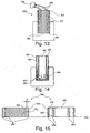
- Fig. 12 shows a table illustrating a possible perfusion fluid with tolerances.
- Fig. 13 shows an arrangement 1300 of a healing dummy 302' having a venting unit 1302 and being inserted into a flexible tubing 304 of a catheter according to an exemplary embodiment of the invention.
- the venting unit 1302 is realized as two through holes extending through the healing dummy 302'.
- Fig. 13 shows an additional optional component of the venting unit 1302, i.e. a pump 1304.
- This pump 1304 may pump a fluid (such as a gas or a liquid) through the through holes while the healing dummy 302' is removed from the tubing 304 so as to actively avoid an underpressure at the interface between the healing dummy 302' and adjacent tissue.
- a fluid such as a gas or a liquid
- Fig. 14 is very similar to the embodiment of Fig. 9 to which explicit reference is made for details. However, in contrast to Fig. 9 , Fig. 14 implements membrane 900 to enclose also a part of the sidewall.
- the membrane 900 can be inserted so that the healing dummy 302' (or healing dummy 302) serves for shaping the membrane 900.
- the membrane 900 can be stretched over the healing dummy during implantation.
- Fig. 15 shows two operation modes of a catheter 1500 according to an exemplary embodiment of the invention.
- One operation mode shows a healing dummy 302 inserted into and flushing with a tubing 304.
- the other operation mode shows a perfusion insert 502 inserted into and flushing with the tubing 304.
- a common flat and planar front surface 1502 of the flushing healing dummy 302 and tubing 304 in the first operation mode equals to or flushes with a common front surface 1504 of flushing perfusion insert 502 and tubing 304.
- a common flushing line 1510 indicates a common end position up to which the healing dummy 302 and tubing 304 arrangement on the left hand side of Fig. 15 as well as the perfusion insert 502 and tubing 304 arrangement on the right hand side of Fig. 15 extend when being implanted in a physiological environment such as a brain.
- the catheter 1500 is configured so that, when the healing dummy 302 is inserted in the lumen of tubing 304 to prevent tissue ingrowth, the healing dummy 302 and the tubing 304 are in flush (i.e. the healing dummy 302 is inserted in the tubing 304 without protruding over the tubing 304), so that the healing dummy 302 and the tubing 304 together form the flat and planar structure at the common front face 1502.
- This flushing between front face of healing dummy 302 and front face of tubing 304 is highly advantageous because this fully avoids anew injury of tissue after primary implantation of the catheter 1500.
- the perfusion insert 502 and the tubing 304 are also in flush and are configured so that, when the perfusion insert 502 is inserted in the lumen of tubing 304, the front surface of the perfusion insert 502 and the front surface of the tubing 304 are aligned to one another.
- the aligned or flushing position (as well as the slight protruding position in other embodiments such as in Fig. 10 ) may be, in an embodiment, defined by cooperating engagement structures (which may form a mechanical locking mechanism) between tubing 304 and healing dummy 302 and/or between tubing 304 and perfusion insert 502.
- cooperating engagement structures which may form a mechanical locking mechanism
- the cooperating engagement structures may come into engagement to thereby prevent further advancing of healing dummy 302 or perfusion insert 502 into the tubing 304 when the flushing position (or a defined slightly protruding position) is reached. This may simplify operation by a user because the user will experience a mechanical blocking when the desired end position is reached.
Landscapes
- Health & Medical Sciences (AREA)
- Life Sciences & Earth Sciences (AREA)
- Heart & Thoracic Surgery (AREA)
- General Health & Medical Sciences (AREA)
- Veterinary Medicine (AREA)
- Engineering & Computer Science (AREA)
- Biomedical Technology (AREA)
- Public Health (AREA)
- Animal Behavior & Ethology (AREA)
- Physics & Mathematics (AREA)
- Biophysics (AREA)
- Surgery (AREA)
- Anesthesiology (AREA)
- Molecular Biology (AREA)
- Hematology (AREA)
- Medical Informatics (AREA)
- Optics & Photonics (AREA)
- Pathology (AREA)
- Pulmonology (AREA)
- Vascular Medicine (AREA)
- Urology & Nephrology (AREA)
- Emergency Medicine (AREA)
- Epidemiology (AREA)
- Oral & Maxillofacial Surgery (AREA)
- Media Introduction/Drainage Providing Device (AREA)
- External Artificial Organs (AREA)
- Reproductive Health (AREA)
- Nuclear Medicine, Radiotherapy & Molecular Imaging (AREA)
Claims (15)
- Ein Katheter (300) zur Implantation in Gewebe, wobei der Katheter (300) aufweist:eine Rohrleitung (304), welche ein Lumen (400) hat und welche zumindest teilweise eine äußere Abgrenzung zwischen dem Katheter (300) und dem Gewebe definiert, wenn der Katheter (300) in das Gewebe implantiert ist;einen Heilungsdummy (302), welcher in das Lumen (400) mit lichtem Abstand einführbar ist, so dass ein Gewebeeinwachsen von dem Gewebe in das Lumen (400) verhindert wird, wenn der Heilungsdummy (302) innerhalb des Lumens (400) ist, wobei
der Heilungsdummy (302) aus dem Lumen (400) entfernbar ist mittels Ziehens des Heilungsdummys (302) relativ zu der Rohrleitung (304) aus dem Lumen (400) heraus;ein Perfusionseinsatz (502), welcherin das Lumen einführbar ist, wenn der Heilungsdummy (302) aus dem Lumen (400) entfernt ist, welcher
konfiguriert ist zum Zuführen eines Perfusionsfluides an das Gewebe, so dass eine Interaktion zwischen dem Perfusionsfluid und dem Gewebe initiiert wird, und welcher
konfiguriert ist zum Sammeln von Perfusionsfluid nach einer Interaktion mit dem Gewebe;
wobei der Heilungsdummy (302) und die Rohrleitung (304) bündig sind,
oder
wobei der Heilungsdummy (302) entlang einer Einführrichtung über die Rohrleitung (304) um einen Abstand in einem Bereich zwischen 0 und 0,5 mm vorsteht. - Der Katheter (300) gemäß dem vorangehenden Anspruch, wobei
der Perfusionseinsatz (502) und die Rohrleitung (304) bündig sind oder
der Perfusionseinsatz (502) entlang einer Einführrichtung über die Rohrleitung (304) um einen Abstand in einem Bereich von 0 und 0,5 mm vorsteht, und/oder wobei
der Katheter (300) ein zerebraler Katheter (300) zur Implantation in ein Gehirn (104) ist, und/oder wobei
die Rohrleitung eine flexible Rohrleitung (304) ist. - Der Katheter (300) gemäß einem beliebigen von Anspruch 1 bis 2, wobei
der Heilungsdummy (302) eine Belüftungseinheit (1302) aufweist, welche konfiguriert ist zum Belüften einer Region zwischen dem Heilungsdummy (302) und dem Gewebe bei einem Ziehen des Heilungsdummys (302) relativ zu der Rohrleitung (304) aus dem Lumen (400) heraus. - Der Katheter (300) gemäß einem beliebigen von Anspruch 1 bis 3, wobei
der Heilungsdummy (302) eine kantenlose, insbesondere abgerundete Oberfläche hat, welche dem Gewebe zugewandt ist, wenn der Heilungsdummy in die Rohrleitung (304) eingeführt wird, und/oder wobei
der Heilungsdummy (302) eine zylindrische Form hat und die Rohrleitung (304) eine hohle zylindrische Form hat, und/oder wobei
der Heilungsdummy (302) konfiguriert ist die Öffnung in der Rohrleitung (304) vollständig auszufüllen, so dass keine Aussparung in der Rohrleitung (304) verbleibt, wenn der Heilungsdummy (302) in die Rohrleitung (304) eingeführt ist. - Der Katheter (300) gemäß einem beliebigen von Anspruch 1 bis 4, wobei
der Perfusionseinsatz (502) konfiguriert ist die Öffnung in die Rohrleitung (304) zu füllen abgesehen von einem oder mehreren Fluidkanälen, welche gebildet sind mittels des Perfusionseinsatzes (102) selbst und/oder
zwischen dem Perfusionseinsatz (502) und der flexiblen Rohrleitung (304), und/oder wobei
eine Oberflächenrauheit der Rohrleitung (304) und/oder des Heilungsdummys (302) in einem Bereich zwischen 1 nm und 100 nm ist, insbesondere in einem Bereich zwischen 1 nm und 50 nm, weiter insbesondere in einem Bereich zwischen 3 nm und 20 nm, und/oder wobei
der lichte Abstand zwischen dem Heilungsdummy (302) und der Rohrleitung (304) mittels eines Beabstandens zwischen einer inneren Oberfläche der Rohrleitung (304) und einer äußeren Oberfläche des Heilungsdummys (302) gebildet ist, wobei das Beabstanden in einem Bereich zwischen 0,01 mm und 0,5 mm ist, insbesondere in einem Bereich zwischen 0,05 mm und 0,2 mm. - Der Katheter (300) gemäß einem beliebigen von Anspruch 1 bis 5, wobei eine Oberfläche des Heilungsdummys (302) und/oder der Rohrleitung (304), welche dem Gewebe zugewandt ist, funktionalisiert ist, und/oder wobei der Heilungsdummy (302) aus einem Fluorpolymer, insbesondere aus Polytetrafluorethylen, hergestellt ist.
- Der Katheter (300) gemäß einem beliebigen von Anspruch 1 bis 6, wobei der Perfusionseinsatz (502) ein hohles zylindrisches Rohr aufweist, welches ein inneres Lumen (400) begrenzt, und welches
zusammen mit der Rohrleitung (304) ein ringförmiges Lumen begrenzt, wobei das innere Lumen (400) konfiguriert ist zum Zuführen des Perfusionsfluides an das Gewebe, und wobei
das ringförmige Lumen konfiguriert ist zum Sammeln des Perfusionsfluides. - Der Katheter (300) gemäß einem beliebigen von Anspruch 1 bis 7, wobei der Perfusionseinsatz (502) eine Multi Lumen Struktur aufweist, welche in ihrem Inneren mehrere Lumen begrenzt, wobei
eines oder mehrere der mehreren Lumen konfiguriert ist/sind zum Zuführen des Perfusionsfluides an das Gewebe, und wobei
eines oder mehrere der mehreren Lumen konfiguriert ist/sind zum Sammeln des Perfusionsfluides. - Der Katheter gemäß einem beliebigen von Anspruch 7 oder 8, aufweisend eines der folgenden Merkmale:der Perfusionseinsatz (502) weist auf eine permeable Membran zwischen den verschiedenen Lumen auf der einen Seite und dem Gewebe, welches den Katheter (300) umgibt, auf der anderen Seite;der Perfusionseinsatz (502) weist auf ein Netz von einer Fadenstruktur zwischen den verschiedenen Lumen auf der einen Seite und dem Gewebe, welches den Katheter (300) umgibt, auf der anderen Seite, wobei das Fadenmaterial der Fadenstruktur impermeabel ist und wobei Lücken zwischen aneinandergrenzenden Abschnitten des Fadenmaterials permeabel sind.
- Der Katheter (300) gemäß einem beliebigen von Anspruch 1 bis 9, wobei
die Rohrleitung (304) eine Wandstärke in einem Bereich zwischen 0,01 mm und 0,3 mm hat, insbesondere in einem Bereich zwischen 0,02 mm und 0,15 mm, und/oder wobei
die flexible Rohrleitung (304) aus einem Material hergestellt ist, welches eine Shore-Härte in einem Bereich zwischen D30 und D90 hat, insbesondere in einem Bereich zwischen D50 und D70, und/oder wobei
der Katheter (300) konfiguriert ist für eine aus der Gruppe bestehend aus Mikro-Perfusion, insbesondere offene Fluss Mikro-Perfusion, und Mikrodialyse. - Ein medizinisches System (100), aufweisend:einen Katheter (300) gemäß einem beliebigen von Anspruch 1 bis 10, welcher konfiguriert ist, um in ein Gewebe eingeführt zu werden;eine Pumpe (506), welche in Fluidkommunikation mit dem Katheter (300) istzum Leiten eines Perfusionsfluides in Richtung des Katheters (300) und
zum Leiten eines Probefluides, welches von einer Interaktion des Perfusionsfluides mit dem Gewebe resultiert, weg von dem Katheter (300). - Das medizinische System (500) gemäß dem vorangehenden Anspruch, aufweisend eine Sensoreinheit (516), an welche
das Probefluid mittels der Pumpe (106) zuführbar ist, und welche konfiguriert ist zum Messen eines physiologischen Parameters, insbesondere mittels Analysierens des Probefluides oder mittels Druckmessens, wobei
die Sensoreinheit (516) insbesondere konfiguriert ist zum kontinuierlichen Überwachen eines physiologischen Parameters mittels Analysierens des Probefluides, und/oder wobei
das medizinische System (500) einen Probefluid Sammelbehälter aufweist, welcher zum Sammeln des Probefluides für eine nachfolgende Offline Analyse konfiguriert ist. - Das medizinische System (500) gemäß einem beliebigen von Anspruch 11 oder 12, wobei
die Pumpe (506) konfiguriert ist zum Leiten des Perfusionsfluides in Richtung des Katheters (300) mit derselben Flussrate gemäß welcher das Probefluid von dem Katheter (300) weggeleitet wird. - Das medizinische System (500) gemäß einem beliebigen von Anspruch 11 bis 13, wobei
der Katheter (300) ein zerebraler Katheter (300) zur Implantation in ein Gehirn (104) ist, wobei
das medizinische System (500) einen Blut-Gehirn-Schranke Integrität Detektor aufweist, welcher konfiguriert ist zum Detektieren, nachdem der Heilungsdummy (302) durch den Perfusionseinsatz (502) ausgetauscht wurde, ob die Blut-Gehirn-Schranke sich nach der Verletzung durch die Implantation des Heilungsdummys (302) erholt hat, insbesondere wobei
der Blut-Gehirn-Schranke Integrität Detektor konfiguriert ist zum Detektieren ob
die Blut-Gehirn-Schranke sich erholt hat durch ein Detektieren ob eine Markersubstanz, welche dem Blut der physiologischen Versuchsperson mittels einer Marker Zufuhreinheit zugeführt wurde, in dem Perfusionsfluid detektierbar ist. - Das medizinische System (500) gemäß einem beliebigen von Anspruch 11 bis 14, wobei
das Perfusionsfluid eine Mischung aufweist aus NaCL, MgCl, CaCl2, KCL, NaH2PO4, Na2HPO4 und/oder Glukose und/oder wobei
das Perfusionsfluid eine Mischung aufweist aus 130±10 mmol/l Na, 4,3±0,5 mmol/l K, 0,72±0,10 mmol/l Ca, 0,40±0,80 mmol/l Mg, 135±10 mmol/l Cl und 3±1 mmol/l Glukose und/oder wobei
das Perfusionsfluid eine Medikation aufweist.
Priority Applications (1)
| Application Number | Priority Date | Filing Date | Title |
|---|---|---|---|
| EP12721537.4A EP2709704B1 (de) | 2011-05-17 | 2012-05-16 | Katheter mit heilungsdummy |
Applications Claiming Priority (3)
| Application Number | Priority Date | Filing Date | Title |
|---|---|---|---|
| EP11166411 | 2011-05-17 | ||
| EP12721537.4A EP2709704B1 (de) | 2011-05-17 | 2012-05-16 | Katheter mit heilungsdummy |
| PCT/EP2012/059192 WO2012156478A1 (en) | 2011-05-17 | 2012-05-16 | Catheter having a healing dummy |
Publications (2)
| Publication Number | Publication Date |
|---|---|
| EP2709704A1 EP2709704A1 (de) | 2014-03-26 |
| EP2709704B1 true EP2709704B1 (de) | 2016-11-30 |
Family
ID=46085978
Family Applications (1)
| Application Number | Title | Priority Date | Filing Date |
|---|---|---|---|
| EP12721537.4A Active EP2709704B1 (de) | 2011-05-17 | 2012-05-16 | Katheter mit heilungsdummy |
Country Status (4)
| Country | Link |
|---|---|
| US (1) | US9656018B2 (de) |
| EP (1) | EP2709704B1 (de) |
| DK (1) | DK2709704T3 (de) |
| WO (1) | WO2012156478A1 (de) |
Families Citing this family (13)
| Publication number | Priority date | Publication date | Assignee | Title |
|---|---|---|---|---|
| CA2917047C (en) | 2013-08-30 | 2019-06-11 | Hollister Incorporated | Device for trans-anal irrigation |
| US10561817B2 (en) | 2014-05-30 | 2020-02-18 | Hollister Incorporated | Flip open catheter package |
| EP3166662B1 (de) | 2014-07-08 | 2023-06-07 | Hollister Incorporated | Transanale irrigationsplattform mit bettmodul |
| AU2015287989C1 (en) | 2014-07-08 | 2020-07-02 | Hollister Incorporated | Portable trans anal irrigation device |
| WO2017174557A2 (en) * | 2016-04-04 | 2017-10-12 | Brains Online Holding B.V. | Use of push pull microdialysis in combination with shotgun proteomics for analyzing the proteome in extracellular space of brain |
| AU2017254706B2 (en) | 2016-04-22 | 2022-04-28 | Hollister Incorporated | Medical device package with a twist cap |
| US11103676B2 (en) | 2016-04-22 | 2021-08-31 | Hollister Incorporated | Medical device package with flip cap having a snap fit |
| LT3481460T (lt) | 2016-07-08 | 2020-07-27 | Hollister Incorporated | Bevielis elektroninis siurblys, skirtas kūno ertmės irigacijos aparatui |
| EP3777921B1 (de) | 2016-12-14 | 2025-08-13 | Hollister Incorporated | Transanales spülungssystem |
| CA3054197A1 (en) | 2017-02-21 | 2018-08-30 | Hollister Incorporated | Medical device package with flip cap having a snap fit |
| LT3700612T (lt) | 2017-10-25 | 2024-07-10 | Hollister Incorporated | Kateterių pakuočių dangteliai |
| EP3720536B1 (de) | 2017-12-08 | 2024-08-14 | Hollister Incorporated | Verpackung für medizinische vorrichtung zur ergonomischen vorrichtungsentnahme |
| EP4208242A1 (de) | 2020-09-04 | 2023-07-12 | Hollister Incorporated | Verpackung für eine medizinische vorrichtung mit indikatoretikett zur ersten verwendung |
Family Cites Families (17)
| Publication number | Priority date | Publication date | Assignee | Title |
|---|---|---|---|---|
| AT391998B (de) * | 1987-02-02 | 1990-12-27 | Falko Dr Skrabal | Vorrichtung zur bestimmung der konzentration zumindest einer medizinischen substanz in lebenden organismen |
| AT398699B (de) * | 1990-07-30 | 1995-01-25 | Avl Verbrennungskraft Messtech | Dialysesonde |
| US5441481A (en) | 1994-05-27 | 1995-08-15 | Mishra; Pravin | Microdialysis probes and methods of use |
| JP4841788B2 (ja) * | 2000-02-04 | 2011-12-21 | コンメド エンドスコピック テクノロジーズ インコーポレイテッド | 3管腔結石バルーン・カテーテルおよびその方法 |
| DE10008825C2 (de) * | 2000-02-25 | 2002-11-21 | Disetronic Licensing Ag | Mikroperfusionsvorrichtung |
| US7357794B2 (en) * | 2002-01-17 | 2008-04-15 | Medtronic Vascular, Inc. | Devices, systems and methods for acute or chronic delivery of substances or apparatus to extravascular treatment sites |
| US6602241B2 (en) | 2001-01-17 | 2003-08-05 | Transvascular, Inc. | Methods and apparatus for acute or chronic delivery of substances or apparatus to extravascular treatment sites |
| US7241283B2 (en) | 2003-04-25 | 2007-07-10 | Ad-Tech Medical Instrument Corp. | Method for intracranial catheter treatment of brain tissue |
| US20060235349A1 (en) | 2005-04-14 | 2006-10-19 | Brett Osborn | Implantable anti-clogging device for maintenance of cerebrospinal fluid shunt patency |
| EP1898799A1 (de) * | 2005-07-06 | 2008-03-19 | Medizinische Universität Graz | Vorrichtung und verfahren zur abgabe und entfernung von substanzen in und aus einem gewebe oder gefäss |
| EP2029195A2 (de) | 2006-05-30 | 2009-03-04 | Yossi Gross | Implantierbare pumpe zur arzneiabgabe zur behandlung von erektiler dysfunktion |
| US8551075B2 (en) * | 2006-06-02 | 2013-10-08 | Kci Medical Resources | Assemblies, systems, and methods for vacuum assisted internal drainage during wound healing |
| US7766394B2 (en) * | 2006-10-30 | 2010-08-03 | Medtronic, Inc. | Breakaway connectors and systems |
| US7819842B2 (en) * | 2006-11-21 | 2010-10-26 | Medtronic, Inc. | Chronically implantable guide tube for repeated intermittent delivery of materials or fluids to targeted tissue sites |
| EP2258416B1 (de) * | 2008-03-26 | 2014-11-26 | Kaneka Corporation | Antithrombotische oberfläche |
| WO2009158007A2 (en) * | 2008-06-27 | 2009-12-30 | Limerick Biopharma, Inc. | Methods and compositions for therapeutic treatment |
| WO2010031515A1 (en) * | 2008-09-17 | 2010-03-25 | Johanneum Research Forschungsgesellschaft Mbh | Filament-based catheter |
-
2012
- 2012-05-16 EP EP12721537.4A patent/EP2709704B1/de active Active
- 2012-05-16 DK DK12721537.4T patent/DK2709704T3/en active
- 2012-05-16 US US14/118,128 patent/US9656018B2/en active Active
- 2012-05-16 WO PCT/EP2012/059192 patent/WO2012156478A1/en not_active Ceased
Also Published As
| Publication number | Publication date |
|---|---|
| WO2012156478A1 (en) | 2012-11-22 |
| DK2709704T3 (en) | 2017-03-13 |
| EP2709704A1 (de) | 2014-03-26 |
| US20140163458A1 (en) | 2014-06-12 |
| US9656018B2 (en) | 2017-05-23 |
Similar Documents
| Publication | Publication Date | Title |
|---|---|---|
| EP2709704B1 (de) | Katheter mit heilungsdummy | |
| EP2023994B1 (de) | Katheter mit länglichem schlitz | |
| US7850666B2 (en) | Catheter infusion port | |
| CA2458966C (en) | Method and system for non-vascular sensor implantation | |
| US8388584B2 (en) | Method and system for the use of hollow fiber catheters in topical applications | |
| EP0902699B1 (de) | Vorrichtung zum injiziereneines stoffes in einen körper,insbesondere einen menschlichen oder einen tierischen körper | |
| WO2009049823A1 (en) | Catheter and methods of operating and manufacturing the same | |
| WO2018138346A1 (de) | Vorrichtung und verfahren zum automatischen entlüften und befüllen eines katheters | |
| KR20200135386A (ko) | 유치 정맥 캐뉼라 | |
| CN119258374A (zh) | 静脉留置套管 | |
| US8460253B2 (en) | Magnetically sealed intravenous access valve | |
| US20080234563A1 (en) | Device for and Method of Delivery and Removal of Substances in and From a Tissue or Vessel | |
| JP6418645B2 (ja) | 溶質および/または溶媒の局所での浸透および拡散を制御する装置、システム、および方法 | |
| WO2007054317A1 (en) | Determining a value of a physiological parameter | |
| CN110582323A (zh) | 用来进入人体或动物体血管系统的植入式进入装置 | |
| DK2884896T3 (en) | Improved fluid sampling system |
Legal Events
| Date | Code | Title | Description |
|---|---|---|---|
| PUAI | Public reference made under article 153(3) epc to a published international application that has entered the european phase |
Free format text: ORIGINAL CODE: 0009012 |
|
| 17P | Request for examination filed |
Effective date: 20131114 |
|
| AK | Designated contracting states |
Kind code of ref document: A1 Designated state(s): AL AT BE BG CH CY CZ DE DK EE ES FI FR GB GR HR HU IE IS IT LI LT LU LV MC MK MT NL NO PL PT RO RS SE SI SK SM TR |
|
| DAX | Request for extension of the european patent (deleted) | ||
| REG | Reference to a national code |
Ref country code: DE Ref legal event code: R079 Ref document number: 602012026013 Country of ref document: DE Free format text: PREVIOUS MAIN CLASS: A61M0025000000 Ipc: A61M0005142000 |
|
| GRAP | Despatch of communication of intention to grant a patent |
Free format text: ORIGINAL CODE: EPIDOSNIGR1 |
|
| RIC1 | Information provided on ipc code assigned before grant |
Ipc: A61M 5/142 20060101AFI20160606BHEP Ipc: A61M 25/00 20060101ALI20160606BHEP Ipc: A61B 5/145 20060101ALI20160606BHEP Ipc: A61M 39/02 20060101ALI20160606BHEP |
|
| INTG | Intention to grant announced |
Effective date: 20160622 |
|
| GRAS | Grant fee paid |
Free format text: ORIGINAL CODE: EPIDOSNIGR3 |
|
| GRAA | (expected) grant |
Free format text: ORIGINAL CODE: 0009210 |
|
| AK | Designated contracting states |
Kind code of ref document: B1 Designated state(s): AL AT BE BG CH CY CZ DE DK EE ES FI FR GB GR HR HU IE IS IT LI LT LU LV MC MK MT NL NO PL PT RO RS SE SI SK SM TR |
|
| REG | Reference to a national code |
Ref country code: CH Ref legal event code: EP Ref country code: GB Ref legal event code: FG4D |
|
| REG | Reference to a national code |
Ref country code: AT Ref legal event code: REF Ref document number: 849219 Country of ref document: AT Kind code of ref document: T Effective date: 20161215 |
|
| REG | Reference to a national code |
Ref country code: IE Ref legal event code: FG4D |
|
| REG | Reference to a national code |
Ref country code: DE Ref legal event code: R096 Ref document number: 602012026013 Country of ref document: DE |
|
| PG25 | Lapsed in a contracting state [announced via postgrant information from national office to epo] |
Ref country code: LV Free format text: LAPSE BECAUSE OF FAILURE TO SUBMIT A TRANSLATION OF THE DESCRIPTION OR TO PAY THE FEE WITHIN THE PRESCRIBED TIME-LIMIT Effective date: 20161130 |
|
| REG | Reference to a national code |
Ref country code: DK Ref legal event code: T3 Effective date: 20170307 |
|
| REG | Reference to a national code |
Ref country code: SE Ref legal event code: TRGR |
|
| REG | Reference to a national code |
Ref country code: LT Ref legal event code: MG4D |
|
| REG | Reference to a national code |
Ref country code: CH Ref legal event code: NV Representative=s name: RIEDERER HASLER AND PARTNER PATENTANWAELTE AG, CH |
|
| REG | Reference to a national code |
Ref country code: NL Ref legal event code: MP Effective date: 20161130 |
|
| PG25 | Lapsed in a contracting state [announced via postgrant information from national office to epo] |
Ref country code: NO Free format text: LAPSE BECAUSE OF FAILURE TO SUBMIT A TRANSLATION OF THE DESCRIPTION OR TO PAY THE FEE WITHIN THE PRESCRIBED TIME-LIMIT Effective date: 20170228 Ref country code: GR Free format text: LAPSE BECAUSE OF FAILURE TO SUBMIT A TRANSLATION OF THE DESCRIPTION OR TO PAY THE FEE WITHIN THE PRESCRIBED TIME-LIMIT Effective date: 20170301 Ref country code: LT Free format text: LAPSE BECAUSE OF FAILURE TO SUBMIT A TRANSLATION OF THE DESCRIPTION OR TO PAY THE FEE WITHIN THE PRESCRIBED TIME-LIMIT Effective date: 20161130 |
|
| REG | Reference to a national code |
Ref country code: FR Ref legal event code: PLFP Year of fee payment: 6 |
|
| PG25 | Lapsed in a contracting state [announced via postgrant information from national office to epo] |
Ref country code: FI Free format text: LAPSE BECAUSE OF FAILURE TO SUBMIT A TRANSLATION OF THE DESCRIPTION OR TO PAY THE FEE WITHIN THE PRESCRIBED TIME-LIMIT Effective date: 20161130 Ref country code: RS Free format text: LAPSE BECAUSE OF FAILURE TO SUBMIT A TRANSLATION OF THE DESCRIPTION OR TO PAY THE FEE WITHIN THE PRESCRIBED TIME-LIMIT Effective date: 20161130 Ref country code: PL Free format text: LAPSE BECAUSE OF FAILURE TO SUBMIT A TRANSLATION OF THE DESCRIPTION OR TO PAY THE FEE WITHIN THE PRESCRIBED TIME-LIMIT Effective date: 20161130 Ref country code: ES Free format text: LAPSE BECAUSE OF FAILURE TO SUBMIT A TRANSLATION OF THE DESCRIPTION OR TO PAY THE FEE WITHIN THE PRESCRIBED TIME-LIMIT Effective date: 20161130 Ref country code: PT Free format text: LAPSE BECAUSE OF FAILURE TO SUBMIT A TRANSLATION OF THE DESCRIPTION OR TO PAY THE FEE WITHIN THE PRESCRIBED TIME-LIMIT Effective date: 20170330 Ref country code: HR Free format text: LAPSE BECAUSE OF FAILURE TO SUBMIT A TRANSLATION OF THE DESCRIPTION OR TO PAY THE FEE WITHIN THE PRESCRIBED TIME-LIMIT Effective date: 20161130 |
|
| PG25 | Lapsed in a contracting state [announced via postgrant information from national office to epo] |
Ref country code: NL Free format text: LAPSE BECAUSE OF FAILURE TO SUBMIT A TRANSLATION OF THE DESCRIPTION OR TO PAY THE FEE WITHIN THE PRESCRIBED TIME-LIMIT Effective date: 20161130 |
|
| PG25 | Lapsed in a contracting state [announced via postgrant information from national office to epo] |
Ref country code: EE Free format text: LAPSE BECAUSE OF FAILURE TO SUBMIT A TRANSLATION OF THE DESCRIPTION OR TO PAY THE FEE WITHIN THE PRESCRIBED TIME-LIMIT Effective date: 20161130 Ref country code: CZ Free format text: LAPSE BECAUSE OF FAILURE TO SUBMIT A TRANSLATION OF THE DESCRIPTION OR TO PAY THE FEE WITHIN THE PRESCRIBED TIME-LIMIT Effective date: 20161130 Ref country code: SK Free format text: LAPSE BECAUSE OF FAILURE TO SUBMIT A TRANSLATION OF THE DESCRIPTION OR TO PAY THE FEE WITHIN THE PRESCRIBED TIME-LIMIT Effective date: 20161130 Ref country code: RO Free format text: LAPSE BECAUSE OF FAILURE TO SUBMIT A TRANSLATION OF THE DESCRIPTION OR TO PAY THE FEE WITHIN THE PRESCRIBED TIME-LIMIT Effective date: 20161130 |
|
| PG25 | Lapsed in a contracting state [announced via postgrant information from national office to epo] |
Ref country code: BG Free format text: LAPSE BECAUSE OF FAILURE TO SUBMIT A TRANSLATION OF THE DESCRIPTION OR TO PAY THE FEE WITHIN THE PRESCRIBED TIME-LIMIT Effective date: 20170228 Ref country code: SM Free format text: LAPSE BECAUSE OF FAILURE TO SUBMIT A TRANSLATION OF THE DESCRIPTION OR TO PAY THE FEE WITHIN THE PRESCRIBED TIME-LIMIT Effective date: 20161130 Ref country code: BE Free format text: LAPSE BECAUSE OF FAILURE TO SUBMIT A TRANSLATION OF THE DESCRIPTION OR TO PAY THE FEE WITHIN THE PRESCRIBED TIME-LIMIT Effective date: 20161130 Ref country code: LU Free format text: LAPSE BECAUSE OF NON-PAYMENT OF DUE FEES Effective date: 20170531 Ref country code: IT Free format text: LAPSE BECAUSE OF FAILURE TO SUBMIT A TRANSLATION OF THE DESCRIPTION OR TO PAY THE FEE WITHIN THE PRESCRIBED TIME-LIMIT Effective date: 20161130 |
|
| REG | Reference to a national code |
Ref country code: DE Ref legal event code: R097 Ref document number: 602012026013 Country of ref document: DE |
|
| PLBE | No opposition filed within time limit |
Free format text: ORIGINAL CODE: 0009261 |
|
| STAA | Information on the status of an ep patent application or granted ep patent |
Free format text: STATUS: NO OPPOSITION FILED WITHIN TIME LIMIT |
|
| 26N | No opposition filed |
Effective date: 20170831 |
|
| PG25 | Lapsed in a contracting state [announced via postgrant information from national office to epo] |
Ref country code: SI Free format text: LAPSE BECAUSE OF FAILURE TO SUBMIT A TRANSLATION OF THE DESCRIPTION OR TO PAY THE FEE WITHIN THE PRESCRIBED TIME-LIMIT Effective date: 20161130 |
|
| PG25 | Lapsed in a contracting state [announced via postgrant information from national office to epo] |
Ref country code: MC Free format text: LAPSE BECAUSE OF FAILURE TO SUBMIT A TRANSLATION OF THE DESCRIPTION OR TO PAY THE FEE WITHIN THE PRESCRIBED TIME-LIMIT Effective date: 20161130 |
|
| REG | Reference to a national code |
Ref country code: IE Ref legal event code: MM4A |
|
| PG25 | Lapsed in a contracting state [announced via postgrant information from national office to epo] |
Ref country code: LU Free format text: LAPSE BECAUSE OF NON-PAYMENT OF DUE FEES Effective date: 20170516 |
|
| PG25 | Lapsed in a contracting state [announced via postgrant information from national office to epo] |
Ref country code: IE Free format text: LAPSE BECAUSE OF NON-PAYMENT OF DUE FEES Effective date: 20170516 |
|
| REG | Reference to a national code |
Ref country code: FR Ref legal event code: PLFP Year of fee payment: 7 |
|
| PG25 | Lapsed in a contracting state [announced via postgrant information from national office to epo] |
Ref country code: MT Free format text: LAPSE BECAUSE OF NON-PAYMENT OF DUE FEES Effective date: 20170516 |
|
| PG25 | Lapsed in a contracting state [announced via postgrant information from national office to epo] |
Ref country code: HU Free format text: LAPSE BECAUSE OF FAILURE TO SUBMIT A TRANSLATION OF THE DESCRIPTION OR TO PAY THE FEE WITHIN THE PRESCRIBED TIME-LIMIT; INVALID AB INITIO Effective date: 20120516 |
|
| PG25 | Lapsed in a contracting state [announced via postgrant information from national office to epo] |
Ref country code: CY Free format text: LAPSE BECAUSE OF NON-PAYMENT OF DUE FEES Effective date: 20161130 |
|
| PG25 | Lapsed in a contracting state [announced via postgrant information from national office to epo] |
Ref country code: MK Free format text: LAPSE BECAUSE OF FAILURE TO SUBMIT A TRANSLATION OF THE DESCRIPTION OR TO PAY THE FEE WITHIN THE PRESCRIBED TIME-LIMIT Effective date: 20161130 |
|
| PG25 | Lapsed in a contracting state [announced via postgrant information from national office to epo] |
Ref country code: TR Free format text: LAPSE BECAUSE OF FAILURE TO SUBMIT A TRANSLATION OF THE DESCRIPTION OR TO PAY THE FEE WITHIN THE PRESCRIBED TIME-LIMIT Effective date: 20161130 |
|
| REG | Reference to a national code |
Ref country code: AT Ref legal event code: UEP Ref document number: 849219 Country of ref document: AT Kind code of ref document: T Effective date: 20161130 |
|
| PG25 | Lapsed in a contracting state [announced via postgrant information from national office to epo] |
Ref country code: AL Free format text: LAPSE BECAUSE OF FAILURE TO SUBMIT A TRANSLATION OF THE DESCRIPTION OR TO PAY THE FEE WITHIN THE PRESCRIBED TIME-LIMIT Effective date: 20161130 Ref country code: IS Free format text: LAPSE BECAUSE OF FAILURE TO SUBMIT A TRANSLATION OF THE DESCRIPTION OR TO PAY THE FEE WITHIN THE PRESCRIBED TIME-LIMIT Effective date: 20170330 |
|
| P01 | Opt-out of the competence of the unified patent court (upc) registered |
Effective date: 20230525 |
|
| PGFP | Annual fee paid to national office [announced via postgrant information from national office to epo] |
Ref country code: DE Payment date: 20250530 Year of fee payment: 14 |
|
| PGFP | Annual fee paid to national office [announced via postgrant information from national office to epo] |
Ref country code: GB Payment date: 20250515 Year of fee payment: 14 Ref country code: DK Payment date: 20250526 Year of fee payment: 14 |
|
| PGFP | Annual fee paid to national office [announced via postgrant information from national office to epo] |
Ref country code: FR Payment date: 20250528 Year of fee payment: 14 |
|
| PGFP | Annual fee paid to national office [announced via postgrant information from national office to epo] |
Ref country code: CH Payment date: 20250605 Year of fee payment: 14 |
|
| PGFP | Annual fee paid to national office [announced via postgrant information from national office to epo] |
Ref country code: AT Payment date: 20250514 Year of fee payment: 14 |
|
| PGFP | Annual fee paid to national office [announced via postgrant information from national office to epo] |
Ref country code: SE Payment date: 20250515 Year of fee payment: 14 |