EP2709818B1 - Verfahren zur streckblasung eines behälters mit einzug der streckstrange während einer verschachtelungsoperation - Google Patents
Verfahren zur streckblasung eines behälters mit einzug der streckstrange während einer verschachtelungsoperation Download PDFInfo
- Publication number
- EP2709818B1 EP2709818B1 EP12725076.9A EP12725076A EP2709818B1 EP 2709818 B1 EP2709818 B1 EP 2709818B1 EP 12725076 A EP12725076 A EP 12725076A EP 2709818 B1 EP2709818 B1 EP 2709818B1
- Authority
- EP
- European Patent Office
- Prior art keywords
- stretch
- rod
- displacement
- mold
- container
- Prior art date
- Legal status (The legal status is an assumption and is not a legal conclusion. Google has not performed a legal analysis and makes no representation as to the accuracy of the status listed.)
- Active
Links
Images




Classifications
-
- B—PERFORMING OPERATIONS; TRANSPORTING
- B29—WORKING OF PLASTICS; WORKING OF SUBSTANCES IN A PLASTIC STATE IN GENERAL
- B29C—SHAPING OR JOINING OF PLASTICS; SHAPING OF MATERIAL IN A PLASTIC STATE, NOT OTHERWISE PROVIDED FOR; AFTER-TREATMENT OF THE SHAPED PRODUCTS, e.g. REPAIRING
- B29C49/00—Blow-moulding, i.e. blowing a preform or parison to a desired shape within a mould; Apparatus therefor
- B29C49/42—Component parts, details or accessories; Auxiliary operations
- B29C49/48—Moulds
- B29C49/4802—Moulds with means for locally compressing part(s) of the parison in the main blowing cavity
- B29C49/4812—Moulds with means for locally compressing part(s) of the parison in the main blowing cavity and welding opposite wall parts of the parisons or preforms to each other
- B29C49/4815—Moulds with means for locally compressing part(s) of the parison in the main blowing cavity and welding opposite wall parts of the parisons or preforms to each other by means of movable mould parts
-
- B—PERFORMING OPERATIONS; TRANSPORTING
- B29—WORKING OF PLASTICS; WORKING OF SUBSTANCES IN A PLASTIC STATE IN GENERAL
- B29C—SHAPING OR JOINING OF PLASTICS; SHAPING OF MATERIAL IN A PLASTIC STATE, NOT OTHERWISE PROVIDED FOR; AFTER-TREATMENT OF THE SHAPED PRODUCTS, e.g. REPAIRING
- B29C49/00—Blow-moulding, i.e. blowing a preform or parison to a desired shape within a mould; Apparatus therefor
- B29C49/08—Biaxial stretching during blow-moulding
- B29C49/10—Biaxial stretching during blow-moulding using mechanical means for prestretching
- B29C49/12—Stretching rods
-
- B—PERFORMING OPERATIONS; TRANSPORTING
- B29—WORKING OF PLASTICS; WORKING OF SUBSTANCES IN A PLASTIC STATE IN GENERAL
- B29C—SHAPING OR JOINING OF PLASTICS; SHAPING OF MATERIAL IN A PLASTIC STATE, NOT OTHERWISE PROVIDED FOR; AFTER-TREATMENT OF THE SHAPED PRODUCTS, e.g. REPAIRING
- B29C49/00—Blow-moulding, i.e. blowing a preform or parison to a desired shape within a mould; Apparatus therefor
- B29C49/42—Component parts, details or accessories; Auxiliary operations
- B29C49/48—Moulds
- B29C49/54—Moulds for undercut articles
- B29C49/541—Moulds for undercut articles having a recessed undersurface
-
- B—PERFORMING OPERATIONS; TRANSPORTING
- B29—WORKING OF PLASTICS; WORKING OF SUBSTANCES IN A PLASTIC STATE IN GENERAL
- B29C—SHAPING OR JOINING OF PLASTICS; SHAPING OF MATERIAL IN A PLASTIC STATE, NOT OTHERWISE PROVIDED FOR; AFTER-TREATMENT OF THE SHAPED PRODUCTS, e.g. REPAIRING
- B29C49/00—Blow-moulding, i.e. blowing a preform or parison to a desired shape within a mould; Apparatus therefor
- B29C49/42—Component parts, details or accessories; Auxiliary operations
- B29C49/48—Moulds
- B29C2049/4879—Moulds characterised by mould configurations
- B29C2049/4892—Mould halves consisting of an independent main and bottom part
-
- B—PERFORMING OPERATIONS; TRANSPORTING
- B29—WORKING OF PLASTICS; WORKING OF SUBSTANCES IN A PLASTIC STATE IN GENERAL
- B29C—SHAPING OR JOINING OF PLASTICS; SHAPING OF MATERIAL IN A PLASTIC STATE, NOT OTHERWISE PROVIDED FOR; AFTER-TREATMENT OF THE SHAPED PRODUCTS, e.g. REPAIRING
- B29C49/00—Blow-moulding, i.e. blowing a preform or parison to a desired shape within a mould; Apparatus therefor
- B29C49/42—Component parts, details or accessories; Auxiliary operations
- B29C49/78—Measuring, controlling or regulating
- B29C2049/7879—Stretching, e.g. stretch rod
-
- B—PERFORMING OPERATIONS; TRANSPORTING
- B29—WORKING OF PLASTICS; WORKING OF SUBSTANCES IN A PLASTIC STATE IN GENERAL
- B29C—SHAPING OR JOINING OF PLASTICS; SHAPING OF MATERIAL IN A PLASTIC STATE, NOT OTHERWISE PROVIDED FOR; AFTER-TREATMENT OF THE SHAPED PRODUCTS, e.g. REPAIRING
- B29C2949/00—Indexing scheme relating to blow-moulding
- B29C2949/07—Preforms or parisons characterised by their configuration
- B29C2949/0715—Preforms or parisons characterised by their configuration the preform having one end closed
-
- B—PERFORMING OPERATIONS; TRANSPORTING
- B29—WORKING OF PLASTICS; WORKING OF SUBSTANCES IN A PLASTIC STATE IN GENERAL
- B29C—SHAPING OR JOINING OF PLASTICS; SHAPING OF MATERIAL IN A PLASTIC STATE, NOT OTHERWISE PROVIDED FOR; AFTER-TREATMENT OF THE SHAPED PRODUCTS, e.g. REPAIRING
- B29C49/00—Blow-moulding, i.e. blowing a preform or parison to a desired shape within a mould; Apparatus therefor
- B29C49/02—Combined blow-moulding and manufacture of the preform or the parison
- B29C49/06—Injection blow-moulding
-
- B—PERFORMING OPERATIONS; TRANSPORTING
- B29—WORKING OF PLASTICS; WORKING OF SUBSTANCES IN A PLASTIC STATE IN GENERAL
- B29C—SHAPING OR JOINING OF PLASTICS; SHAPING OF MATERIAL IN A PLASTIC STATE, NOT OTHERWISE PROVIDED FOR; AFTER-TREATMENT OF THE SHAPED PRODUCTS, e.g. REPAIRING
- B29C49/00—Blow-moulding, i.e. blowing a preform or parison to a desired shape within a mould; Apparatus therefor
- B29C49/42—Component parts, details or accessories; Auxiliary operations
- B29C49/56—Opening, closing or clamping means
- B29C49/5612—Opening, closing or clamping means characterised by bottom part movement
-
- B—PERFORMING OPERATIONS; TRANSPORTING
- B29—WORKING OF PLASTICS; WORKING OF SUBSTANCES IN A PLASTIC STATE IN GENERAL
- B29K—INDEXING SCHEME ASSOCIATED WITH SUBCLASSES B29B, B29C OR B29D, RELATING TO MOULDING MATERIALS OR TO MATERIALS FOR MOULDS, REINFORCEMENTS, FILLERS OR PREFORMED PARTS, e.g. INSERTS
- B29K2267/00—Use of polyesters or derivatives thereof as reinforcement
Definitions
- the invention relates to the manufacture of containers by stretch blow molding from plastic blanks such as polyethylene terephthalate (PET).
- plastic blanks such as polyethylene terephthalate (PET).
- a blank comprises a body, generally cylindrical of revolution, a neck, which constitutes the rim of the container to be formed, and a bottom which closes the body opposite the collar.
- the conventional manufacturing technique consists in introducing the blank, previously heated to a temperature above the glass transition temperature of the material (about 80 ° C. in the case of PET), in a mold provided with a wall defining a cavity to the impression of the container, and to inject into the blank, through the neck, a fluid, such as a gas (usually air), under pressure to press the material against the wall of the mold.
- a fluid such as a gas (usually air)
- the material softened by the heating forms a bubble which swells and develops both in an axial direction, parallel to the main axis of the mold, and in a radial direction, perpendicular to the axis of the mold.
- the axial stretching of the blank is forced by means of an axially displaceable rod in the mold, this rod comprising a distal end pushing back the bottom of the blank until it comes to press against a mold bottom to the footprint of the bottom of the container.
- the displacement control of the mold bottom is generally pneumatic.
- the pressure required to move the mold bottom is high, since it is necessary to overcome the resistance due to the blowing pressure (greater than 25 bars) prevailing in the container.
- the drawing rod must be maintained pressed against the mold bottom during boxing, in order to limit the risk of slipping (and thus of misalignment) of the bottom of the container during the movement of the mold bottom.
- the pneumatic control of the drawing rod does not prohibit boxing, since the thrust exerted by the mold bottom on which applies a pressure greater than 25 bar is much greater than the resistance (negligible, in comparison) exerted by the elongation rod, whose control pressure is only about 7 bars.
- the kinetics of the boxing a function of the inertia of the mold bottom and its speed of displacement (high to avoid the phenomenon of pinching of the material between the bottom and the wall of the mold), is such that the withdrawal movement elongation rod under the push of the mold bottom can be uncontrolled. Bouncing phenomena of the rod may occur, which may cause a marking of the bottom of the container, and promote a sliding thereof when the loss of contact of the rod.
- the document WO99 / 52701 A1 describes a method of manufacturing a container according to the preamble of claim 1 and a container stretching assembly according to the preamble of claim 2.
- the invention aims to overcome the aforementioned drawbacks, by proposing a solution to limit the risk of deformation or damage to it during boxing.
- the rod is mounted on a movable carriage disengageably, by example via a movable connecting piece.
- This connecting piece may comprise a piston mounted in a jacket which it separates into two chambers, at least one of which is connected to a fluid distributor.
- the piston is preferably displaceable over a predetermined stroke, equal to a stroke of the mold bottom.
- the blow-molding assembly comprises means for detecting the position of the mold base, such as at least one sensor connected to the control unit.
- the device for controlling the displacement of the rod is preferably electromagnetic.
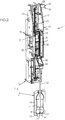
- the machine 1 is equipped with a series of individual stretch-blow assemblies 7 , mounted on a carousel (not shown) rotated about a central axis.
- Each set 7 stretching stretch such as that shown on the Figures 1 to 3 , comprises a mold 8, a drawing unit 9 and blowing means, known per se and not shown.
- the mold 8 is for example of the wallet type and comprises two half-molds articulated around a common hinge and which open to allow, successively, the evacuation of a container 2 formed and the introduction of a preform 3 to be formed, previously heated in a heating unit.
- the mobility of the bottom 13 of the mold makes it possible to overetch the bottom of the container 2, during an operation called "boxing".
- the displacement of the bottom 13 of the mold is for example provided by a double-acting jack supplied with gas under pressure.
- the output position of the mold bottom 13 corresponds to a low position, and its position retracted to a high position.
- the bottom 13 of the mold has an upper surface 14 which, in the upper position of the bottom 13, closes the cavity 11 by closing the opening 12, thus completing the impression against which the material is applied during the blowing of the container 2.
- the stretching unit 9 comprises a frame 15 fixed to the carousel of the machine 1, which extends vertically substantially vertically above the mold 8.
- the frame 15 has a U-shaped profile in cross-section and comprises a wall 16 bottom lined with two side walls 17 .
- the unit 9 drawing is provided with a locking device 25 of the carriage 19 in the high position, which comprises a hook 26 fixed in the upper part of the carriage 19, and a latch 27 fixed to one of the side walls 17 of the frame 15, the latch 27 being provided with a movable bolt 28 on which the hook 26 engages in the up position ( figure 1 ) of the carriage 19.
- the position of the carriage 19 is momentarily locked to the position of the bottom 13 of the mold.
- the set point of the bottom 13 of the mold is for example delivered by detection means, such as at least one sensor 33, able to determine the linear position of the bottom 13 of the mold along the X axis of the mold 8.
- the detection means (in this case the sensor 33 ) are for example of the magnetic type, and they can in this case be placed opposite a magnetic track fixed on the bottom 13 of the mold. In alternatively, it may be one or more capacitive sensors provided with a plurality of sensitive elements successively detecting the presence of a portion of the mold 8.
- the rod 21 is disengageable, the control unit 32 being programmed to control a momentary release of the rod 21 allowing it a free axial movement on a predetermined stroke.
- the manufacture of a container 2 boxed bottom is performed as follows.
- a first phase is to introduce into the mold 8 the preform 3, previously heated to a temperature above the glass transition temperature of the material (about 80 ° C in the case of PET).
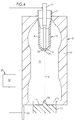
- the control device 29 causes the unlocking and then the displacement of the carriage 19 (and therefore of the drawing rod 21 ) from the high position to a starting position in which the free end 24 of the rod 21 comes into contact with the bottom 6 of the preform 3 ( figure 4 ).
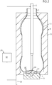
- a second phase consists in injecting into the preform 3 a fluid (normally air) at an average pre-blast pressure of between 5 bars and 15 bars, while moving the rod 21 of stretching from its starting position to its low position, the bottom 13 of the mold being maintained in its extended (low) position.
- a fluid normally air
- the speed of movement of the drawing rod 21 is adjusted so as to maintain contact between the free end 24 of the rod 21 and the bottom 6 of the preform 3.
- the lower position of the drawing rod 21 is adjusted so that a gap 34 is provided between the free end 24 of the rod 21 and the upper surface 14 of the mold base 13 .
- the value of this predetermined interstice 34 is less than or equal to the local thickness of material at the bottom center 6.
- the gap 34 is preferably between 0.2 and 1 mm (for example from about 0.5 mm).
- the bottom 13 of the mold has at its center a recess 35 in which recess is received, at the end of the drawing, a pellet 36 remaining molding of the preform 3.
- the drawing rod 21 retains the pellet 36 in the reserve 35 and thus ensures the transverse locking of the bottom 6, avoiding its sliding during the third phase of the process, called boxing.
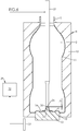
- the boxing phase consists in moving the bottom 13 of the mold, initially in the extended position, towards its retracted position, and completing the blow-molding of the container 2 by injecting into the preform 3, during the ascent of the bottom 13 of the mold, a fluid (air) at a high pressure (called blowing, greater than 25 bars).
- the blowing pressure is maintained for a predetermined time - called the stabilization period - after the mold bottom 13 has reached its high position.
- the blowing pressure intimately adheres the material against the wall 10 of the mold 8 and the upper surface 14 of the bottom 13 of the mold, thus conforming the container 2 to the cavity cavity 11.
- the boxing phase comprises a retraction operation which consists, during the displacement of the mold base 13 towards its retracted position (in other words during the ascent of the mold base 13 towards its upper position), according to the invention, to moving the drawing rod 21 in synchronism (or servo-control) with the bottom 13 of the mold, keeping the gap 34 constant between the free end 24 of the rod 21 and the upper surface 14 of the bottom 13 of the mold. In this way, the rod 21 integrally accompanies the movement of the bottom 13 of the mold.
- the displacement of the rod 21 is not passive (that is to say that the rod 21 is not pushed by the bottom 13 during its ascent) but active: this movement is controlled by the device 29 electromagnetic control, which delivers to motors 30 a control signal for raising the carriage 19, that is to say moving it towards its upper position.
- the electrical command delivered by the control device 29 is slaved according to at least one set point of the bottom 13 of the mold, delivered by the sensor 33.
- the connecting piece 37 includes a flange 38 for the rigid attachment of the rod 21 at its upper end 22 .
- the connecting piece 37 comprises (or is preferably shaped in) a piston 39 received in a jacket 40 formed in the bracket 20.
- the distributor 43 is controlled by the control unit 32 .
- the piston 39 and the jacket 40 are dimensioned so that the stroke of the piston 39 is equal to the stroke of the bottom 13 of the mold during the boxing operation.
- the lower chamber 42 is simply permanently connected to the open air by a bore made in the bracket 20 , while the upper chamber 41 is connected to a three-way distributor and two positions: a load position in which the upper chamber 41 is in communication with the source of fluid pressure, and an exhaust position in which the upper chamber 41 is placed in communication with an exhaust.
- the rod remains secured to the carriage 19, but it is the coupling thereof to the motors 30 which is disengageable, the release of the carriage 19 (and thus the rod 21 ) being controlled by the control unit 32 .
- control unit 32 which is normally programmed to apply to the carriage 19, via the motors 30, a electromotive force directed downwards (during the descent of the rod 21 ) or upwards (during the ascent of the rod 21 ) is also programmed to modify, for example by canceling momentarily during the duration of the boxing operation, the electromotive force reference applied to the rod 21, in order to release it and allow the recovery of the bottom 13 of mold without resistance.
- a stop electromagnetic for the rod 21 may be performed by programming a rise of the rod 21 during boxing, on an equal stroke (or slightly higher, to maintain a margin of safety) to that of the bottom 13 of the mold. Given the simultaneous cancellation of the electromotive force, the rod 21 remains free during boxing, but can not go back beyond its programmed end of travel.
- the operation is as follows.
- the distributor 43 is in the load position, the position of the rod 21, devoid of any axial displacement, being determined by the control unit 32 which ensures the displacement of the carriage 19 (in the direction of the arrow on the figure 8 ). This configuration is maintained as the rod 21 has not reached its low position.
- the displacement of the mold base 13 and the release of the rod 21 are controlled simultaneously by the control unit 32 .
- the rod 21 then opposes any resistance (other than its own weight) to the rise of the bottom 13 mold, as it has not reached its high position.
- the rise of the rod 21 during boxing (in the direction of the arrow on the figure 10 ) is passive, the rod 21 is simply pushed back by the bottom 13 of the mold a distance equal to its stroke.
- a fourth phase consists, at the end of the stabilization period, in venting the container 2 thus formed.
- the pressure then drops until it reaches asymptotically the atmospheric pressure.
- the bottom 13 of the mold is moved to its lower position, the carriage 19 (with the rod 21 ) is raised to the high position, the mold 8 is open and the container 2 formed is removed to allow the cycle to be repeated.
- the bottom 13 retains its output (low) position while the rod 21 descends from the high position to the low position, the latter being reached when the rod 21 reaches the height of the center from the bottom 13, increased by the gap 34.
- the bottom 13 and the rod 21 are simultaneously raised to their respective high positions, the gap 34 between them remaining constant. It can be seen that after the bottom 13 and the stem have both reached their high positions, they are temporarily held in this position for at least the stabilization period. Then degassing occurs, followed by the rise of the stem 21.
- the delivery of the dispenser 43 in the load position can be controlled during the ascent of the rod 21, when the distance separating it from the bottom of the container 2 is sufficient.
Landscapes
- Engineering & Computer Science (AREA)
- Manufacturing & Machinery (AREA)
- Mechanical Engineering (AREA)
- Blow-Moulding Or Thermoforming Of Plastics Or The Like (AREA)
- Container Filling Or Packaging Operations (AREA)
- Moulds For Moulding Plastics Or The Like (AREA)
Claims (5)
- Verfahren zur Herstellung eines Behälters (2) ausgehend von einem Rohling (3) aus Kunststoff, in einer Streckblaseinheit (7), die ausgestattet ist mit:- einem Formwerkzeug (8), das mit einer Wand (10), die einen Hohlraum (11) mit dem Abdruck des Behälters (2) definiert, der sich gemäß einer Hauptachse (X) des Formwerkzeugs (8) erstreckt, und mit einem Formwerkzeugboden (13) versehen ist, der axial bezüglich der Wand (10) zwischen einer ausgetretenen Stellung und einer eingezogenen Stellung verschiebbar ist,- einer Streckeinheit (9), die eine Streckstange (21), die axial bezüglich der Wand (10) verschiebbar ist, und eine Vorrichtung (29) zum Steuern der Verschiebung der Streckstange (21) enthält,wobei dieses Verfahren enthält:- eine Phase des Einführens des Rohlings (3) in das Formwerkzeug (8),- eine Phase des Streckblasens, bei der ein unter Druck stehendes Fluid in den Rohling (3) eingespritzt und die Streckstange (21) in Richtung des Bodens (13) des Formwerkzeugs verschoben wird, bis sie den Rohling (3) lokal gegen den Formwerkzeugboden (13) drückt;- eine Phase des Treibens, bei der der Boden (13) des Formwerkzeugs, der ursprünglich in der ausgetretenen Stellung ist, in seine eingezogene Stellung verschoben wird;Verfahren, das derart ist, dass es einen Einziehvorgang enthält, der während der Treibphase darin besteht, eine Verschiebung der Streckstange (21) synchron mit der Verschiebung des Bodens (13) des Formwerkzeugs zu steuern, wobei das Verfahren dadurch gekennzeichnet ist, dass die Verschiebesteuerung der Streckstange (21) von der Verschiebung des Bodens (13) des Formwerkzeugs abhängig ist, indem der Zwischenraum (34) zwischen dem freien Ende (24) der Stange (21) und der Oberfläche (14) des Bodens (13) des Formwerkzeugs konstant gehalten wird.
- Streckblaseinheit (7) eines Behälters (2) ausgehend von einem Rohling (3) aus Kunststoff, die enthält:- ein Formwerkzeug (8), das mit einer Wand (10) versehen ist, die einen Hohlraum (11) mit dem Abdruck des Behälters (2) definiert, der sich gemäß einer Hauptachse (X) erstreckt,- einen Formwerkzeugboden (13), der axial bezüglich der Wand (10) zwischen einer ausgetretenen Stellung und einer eingezogenen Stellung verschiebbar ist,- eine Streckeinheit (9) mit einer Streckstange (21), die axial bezüglich der Wand (10) verschiebbar ist, und einer Vorrichtung (29) zum Steuern der Verschiebung der Streckstange (21), derart, dass die Steuervorrichtung (29) eine Kontrolleinheit (32) enthält, die so programmiert ist, dass sie in einer Treibphase, die darin besteht, den Boden (13) des Formwerkzeugs von seiner ausgetretenen Stellung in seine eingezogene Stellung zu verschieben, eine Verschiebung der Streckstange (21) synchron mit der Verschiebung des Bodens (13) des Formwerkzeugs steuert,dadurch gekennzeichnet, dass die Steuerung der Verschiebung der Streckstange (21) von der Verschiebung des Bodens (13) des Formwerkzeugs abhängt, indem der Zwischenraum (34) zwischen dem freien Ende (24) der Stange (21) und der Oberfläche (14) des Bodens (13) des Formwerkzeugs konstant gehalten wird.
- Streckblaseinheit (7) nach Anspruch 2, dadurch gekennzeichnet, dass die Steuervorrichtung (29) der Verschiebung der Streckstange (21) elektromagnetisch ist.
- Streckblaseinheit (7) nach einem der Ansprüche 2 bis 3, dadurch gekennzeichnet, dass sie Einrichtungen zur Erfassung/Überwachung der Stellung des Bodens (13) des Formwerkzeugs enthält, wie mindestens einen Sensor (33), der mit der Kontrolleinheit (32) verbunden ist.
- Maschine (1) zur Herstellung von Behältern durch Streckblasen ausgehend von Rohlingen (3) aus Kunststoff, die mit einer oder mehreren Streckblaseinheiten (7) nach einem der Ansprüche 2 bis 4 ausgestattet ist.
Applications Claiming Priority (2)
| Application Number | Priority Date | Filing Date | Title |
|---|---|---|---|
| FR1154354A FR2975331B1 (fr) | 2011-05-19 | 2011-05-19 | Procede d'etirage soufflage d'un recipient, comprenant une retraction de la tige d'etirage au cours d'une operation de boxage |
| PCT/FR2012/050964 WO2012156614A1 (fr) | 2011-05-19 | 2012-04-30 | Procédé d'étirage soufflage d'un récipient, comprenant une rétraction de la tige d'étirage au cours d'une opération de boxage |
Publications (2)
| Publication Number | Publication Date |
|---|---|
| EP2709818A1 EP2709818A1 (de) | 2014-03-26 |
| EP2709818B1 true EP2709818B1 (de) | 2018-08-22 |
Family
ID=46201700
Family Applications (1)
| Application Number | Title | Priority Date | Filing Date |
|---|---|---|---|
| EP12725076.9A Active EP2709818B1 (de) | 2011-05-19 | 2012-04-30 | Verfahren zur streckblasung eines behälters mit einzug der streckstrange während einer verschachtelungsoperation |
Country Status (6)
| Country | Link |
|---|---|
| US (1) | US9688013B2 (de) |
| EP (1) | EP2709818B1 (de) |
| CN (1) | CN103547432B (de) |
| FR (1) | FR2975331B1 (de) |
| MX (1) | MX347627B (de) |
| WO (1) | WO2012156614A1 (de) |
Families Citing this family (18)
| Publication number | Priority date | Publication date | Assignee | Title |
|---|---|---|---|---|
| FR2998207B1 (fr) * | 2012-11-20 | 2015-01-16 | Sidel Participations | Procede d'etirage soufflage d'un recipient, comprenant une mesure du deplacement de la tige d'etirage au cours d'une operation de boxage |
| FR3019486B1 (fr) * | 2014-04-02 | 2016-12-23 | Sidel Participations | Procede de fabrication et unite de moulage de recipients a grande course de boxage |
| FR3023503B1 (fr) * | 2014-07-11 | 2016-07-29 | Sidel Participations | Mesure de la course de boxage par la fonction etirage, dans une installation de fabrication de recipients |
| FR3024071B1 (fr) | 2014-07-25 | 2016-08-19 | Sidel Participations | Procede de controle d'un procede de soufflage de recipients en matiere plastique |
| FR3027248B1 (fr) * | 2014-10-17 | 2016-12-09 | Sidel Participations | Moule a plan de joint sureleve pour la fabrication de recipients |
| FR3029133B1 (fr) * | 2014-11-27 | 2016-12-30 | Sidel Participations | Procede de fabrication de recipient a boxage cale sur le soufflage |
| JP6437379B2 (ja) * | 2015-04-30 | 2018-12-12 | 株式会社吉野工業所 | 液体ブロー成形装置および液体ブロー成形方法 |
| JP6860494B2 (ja) * | 2015-10-29 | 2021-04-14 | 日精エー・エス・ビー機械株式会社 | 金型ユニット、ブロー成形装置、およびブロー成形方法 |
| FR3053271B1 (fr) | 2016-06-29 | 2018-07-27 | Sidel Participations | Procede de fabrication par etirage soufflage d'un recipient a vitesse d'etirage elevee |
| DE102016125586A1 (de) * | 2016-12-23 | 2018-06-28 | Krones Aktiengesellschaft | Verfahren und Vorrichtung zum Blasformen von Behältnissen mit beweglichem Bodenteil |
| DE102016125654A1 (de) * | 2016-12-23 | 2018-06-28 | Krones Ag | Verfahren und Vorrichtung zum Blasformen von Behältnissen mit beweglichem Bodenteil |
| DE102016125552A1 (de) * | 2016-12-23 | 2018-06-28 | Krones Ag | Verfahren und Vorrichtung zum Blasformen von Behältnissen mit beweglichem Bodenteil |
| FR3063926B1 (fr) * | 2017-03-17 | 2019-04-12 | Sidel Participations | Procede de reglage automatique de la course d'une tige d'etirage d'un dispositif de formage de corps creux |
| FR3072321B1 (fr) * | 2017-10-16 | 2019-09-27 | Sidel Participations | Unite de moulage equipee d'un systeme de boxage a electrovanne proportionnelle |
| FR3079442B1 (fr) * | 2018-03-28 | 2020-03-13 | Sidel Participations | Procede de fabrication de recipients, par boxage ajustable en fonction de la courbe de soufflage |
| FR3080795B1 (fr) | 2018-05-02 | 2020-04-03 | Sidel Participations | Procede de formage de recipient en materiau thermoplastique par etirage bi-axial |
| DE102019131242B4 (de) * | 2019-11-19 | 2022-12-15 | Khs Gmbh | Verfahren und Vorrichtung zur Herstellung von Behältern aus Vorformlingen |
| EP4259536A4 (de) * | 2020-12-10 | 2024-08-14 | Amcor Rigid Packaging USA, LLC | Behälterboden mit tiefen eingeformten aussparungen |
Family Cites Families (11)
| Publication number | Priority date | Publication date | Assignee | Title |
|---|---|---|---|---|
| US4009980A (en) * | 1975-07-23 | 1977-03-01 | Package Machinery Company | Injection blow molding machine having movable parison pins |
| DE2717365A1 (de) * | 1977-04-20 | 1978-10-26 | Bekum Maschf Gmbh | Verfahren zur herstellung von hohlkoerpern aus thermoplastischem kunststoff |
| FR2662631B3 (fr) | 1990-05-31 | 1992-09-04 | Dynaplast Sa | Machine pour le soufflage d'emballages en pet bi-oriente ainsi que le procede de soufflage mis en óoeuvre. |
| JP3325074B2 (ja) * | 1993-03-19 | 2002-09-17 | 日精エー・エス・ビー機械株式会社 | 容器の成形方法 |
| CH692492A5 (fr) * | 1998-03-25 | 2002-07-15 | Tetra Pak Plastics Ltd Tetra P | Machine de moulage par étirage-soufflage. |
| US6277321B1 (en) * | 1998-04-09 | 2001-08-21 | Schmalbach-Lubeca Ag | Method of forming wide-mouth, heat-set, pinch-grip containers |
| WO2000038902A1 (en) | 1998-12-28 | 2000-07-06 | A.K. Technical Laboratory, Inc. | Wide-mouthed container bottom molding method using stretch blow molding |
| FR2798093B1 (fr) | 1999-09-03 | 2001-11-30 | Sidel Sa | Machine rotative d'etirage-soufflage comportant une commande magnetique de la tige d'etirage |
| TW200410812A (en) * | 2002-12-12 | 2004-07-01 | A K Tech Lab Inc | Elongation drive device of stretch rod in stretch blow molding machine and bottom-type lifting drive device |
| DE10349753A1 (de) * | 2003-10-24 | 2005-06-02 | Sig Technology Ltd. | Behälter zur Aufnahme von Flüssigkeiten sowie Verfahren zur Behälterherstellung |
| FR2943941B1 (fr) * | 2009-04-02 | 2011-04-22 | Sidel Participations | Unite porte-moule avec tuyere pilotee |
-
2011
- 2011-05-19 FR FR1154354A patent/FR2975331B1/fr not_active Expired - Fee Related
-
2012
- 2012-04-30 US US14/115,717 patent/US9688013B2/en active Active
- 2012-04-30 MX MX2013013089A patent/MX347627B/es active IP Right Grant
- 2012-04-30 WO PCT/FR2012/050964 patent/WO2012156614A1/fr not_active Ceased
- 2012-04-30 CN CN201280024180.6A patent/CN103547432B/zh not_active Expired - Fee Related
- 2012-04-30 EP EP12725076.9A patent/EP2709818B1/de active Active
Non-Patent Citations (1)
| Title |
|---|
| None * |
Also Published As
| Publication number | Publication date |
|---|---|
| MX2013013089A (es) | 2013-12-02 |
| US20140203481A1 (en) | 2014-07-24 |
| EP2709818A1 (de) | 2014-03-26 |
| FR2975331B1 (fr) | 2014-03-07 |
| CN103547432B (zh) | 2017-05-17 |
| WO2012156614A1 (fr) | 2012-11-22 |
| CN103547432A (zh) | 2014-01-29 |
| FR2975331A1 (fr) | 2012-11-23 |
| MX347627B (es) | 2017-05-04 |
| US9688013B2 (en) | 2017-06-27 |
Similar Documents
| Publication | Publication Date | Title |
|---|---|---|
| EP2709818A1 (de) | Verfahren zur streckblasung eines behälters mit einzug der streckstrange während einer verschachtelungsoperation | |
| CA2423702C (fr) | Machine d'etirage-soufflage comportant une commande perfectionnee de la tige d'etirage | |
| EP3126117B1 (de) | Verfahren und gussform zur herstellung von behältern | |
| FR2765515A1 (fr) | Dispositif et procede de fabrication d'un objet en matiere plastique par soufflage | |
| EP2919963B1 (de) | Verfahren zur herstellung von behältern mit verzögertem kartonierungsbetrieb | |
| EP2922682A1 (de) | Verfahren zum streckblasformen eines behälters mit messung der bewegung der streckstange während eines verschachtelungsbetriebs | |
| FR2939073A1 (fr) | Formage des recipients avec contre-pression localisee | |
| WO2012156638A1 (fr) | Procede de fabrication de recipients, comprenant une operation anticipee de boxage | |
| WO2015055499A1 (fr) | Unité de moulage pour la fabrication de récipients comportant une pince de compensation | |
| EP2205425A2 (de) | Verfahren und maschine zur herstellung von behältern mit zwischenzeitlichem druckabbauvorgang | |
| WO2017103494A1 (fr) | Fond de moule pourvu d'un insert mobile central | |
| EP3181327B1 (de) | Giessformboden mit grossen auslassöffnungen für das formverfahren eines behälters | |
| EP2421691B1 (de) | Verbesserter blasdorn zu herstellung von behältern | |
| WO2016087761A1 (fr) | Procédé de formage de récipients, avec freinage d'une tige d'étirage pendant le soufflage | |
| WO2014167235A1 (fr) | Moule à plan de joint déporté pour la fabrication de récipients à stabilité accrue | |
| EP3263312B2 (de) | Herstellungsverfahren durch streckblasformen eines behälters mit hoher streckgeschwindigkeit | |
| EP3206856A1 (de) | Form mit erhöhter wand zur herstellung von behältern | |
| EP3774277B1 (de) | Verfahren zur herstellung von behältern durch je nach blaskurve einstellbarem einpacken | |
| FR3072321B1 (fr) | Unite de moulage equipee d'un systeme de boxage a electrovanne proportionnelle | |
| WO2017077209A1 (fr) | Moule equipe d'une tige de contre-etirage interchangeable | |
| FR3004381A1 (fr) | Moule de soufflage a fond mobile et plan de joint horizontal | |
| FR3151783A1 (fr) | Unité de moulage de récipients avec système de décollement du fond | |
| WO2018109327A1 (fr) | Machine et procede de moulage de preformes par injection compression | |
| EP2909001A1 (de) | Verfahren zur herstellung eines behälters durch streckblasen, wobei ein teil der wand des behälters nicht geformt wird | |
| FR3088572A1 (fr) | Procédé de fabrication d’un récipient en matière plastique muni d’une poignée obtenue par boxage. |
Legal Events
| Date | Code | Title | Description |
|---|---|---|---|
| PUAI | Public reference made under article 153(3) epc to a published international application that has entered the european phase |
Free format text: ORIGINAL CODE: 0009012 |
|
| 17P | Request for examination filed |
Effective date: 20131021 |
|
| AK | Designated contracting states |
Kind code of ref document: A1 Designated state(s): AL AT BE BG CH CY CZ DE DK EE ES FI FR GB GR HR HU IE IS IT LI LT LU LV MC MK MT NL NO PL PT RO RS SE SI SK SM TR |
|
| DAX | Request for extension of the european patent (deleted) | ||
| STAA | Information on the status of an ep patent application or granted ep patent |
Free format text: STATUS: EXAMINATION IS IN PROGRESS |
|
| 17Q | First examination report despatched |
Effective date: 20161027 |
|
| RIC1 | Information provided on ipc code assigned before grant |
Ipc: B29C 49/06 20060101ALN20180409BHEP Ipc: B29C 49/18 20060101AFI20180409BHEP Ipc: B29C 49/54 20060101ALI20180409BHEP Ipc: B29C 49/78 20060101ALN20180409BHEP Ipc: B29K 267/00 20060101ALN20180409BHEP Ipc: B29C 49/12 20060101ALI20180409BHEP Ipc: B29C 49/48 20060101ALN20180409BHEP |
|
| GRAP | Despatch of communication of intention to grant a patent |
Free format text: ORIGINAL CODE: EPIDOSNIGR1 |
|
| STAA | Information on the status of an ep patent application or granted ep patent |
Free format text: STATUS: GRANT OF PATENT IS INTENDED |
|
| INTG | Intention to grant announced |
Effective date: 20180518 |
|
| GRAS | Grant fee paid |
Free format text: ORIGINAL CODE: EPIDOSNIGR3 |
|
| GRAA | (expected) grant |
Free format text: ORIGINAL CODE: 0009210 |
|
| STAA | Information on the status of an ep patent application or granted ep patent |
Free format text: STATUS: THE PATENT HAS BEEN GRANTED |
|
| AK | Designated contracting states |
Kind code of ref document: B1 Designated state(s): AL AT BE BG CH CY CZ DE DK EE ES FI FR GB GR HR HU IE IS IT LI LT LU LV MC MK MT NL NO PL PT RO RS SE SI SK SM TR |
|
| REG | Reference to a national code |
Ref country code: GB Ref legal event code: FG4D Free format text: NOT ENGLISH |
|
| REG | Reference to a national code |
Ref country code: CH Ref legal event code: EP |
|
| REG | Reference to a national code |
Ref country code: AT Ref legal event code: REF Ref document number: 1031943 Country of ref document: AT Kind code of ref document: T Effective date: 20180915 |
|
| REG | Reference to a national code |
Ref country code: IE Ref legal event code: FG4D Free format text: LANGUAGE OF EP DOCUMENT: FRENCH |
|
| REG | Reference to a national code |
Ref country code: DE Ref legal event code: R096 Ref document number: 602012050071 Country of ref document: DE |
|
| REG | Reference to a national code |
Ref country code: NL Ref legal event code: MP Effective date: 20180822 |
|
| REG | Reference to a national code |
Ref country code: LT Ref legal event code: MG4D |
|
| PG25 | Lapsed in a contracting state [announced via postgrant information from national office to epo] |
Ref country code: SE Free format text: LAPSE BECAUSE OF FAILURE TO SUBMIT A TRANSLATION OF THE DESCRIPTION OR TO PAY THE FEE WITHIN THE PRESCRIBED TIME-LIMIT Effective date: 20180822 Ref country code: NL Free format text: LAPSE BECAUSE OF FAILURE TO SUBMIT A TRANSLATION OF THE DESCRIPTION OR TO PAY THE FEE WITHIN THE PRESCRIBED TIME-LIMIT Effective date: 20180822 Ref country code: NO Free format text: LAPSE BECAUSE OF FAILURE TO SUBMIT A TRANSLATION OF THE DESCRIPTION OR TO PAY THE FEE WITHIN THE PRESCRIBED TIME-LIMIT Effective date: 20181122 Ref country code: BG Free format text: LAPSE BECAUSE OF FAILURE TO SUBMIT A TRANSLATION OF THE DESCRIPTION OR TO PAY THE FEE WITHIN THE PRESCRIBED TIME-LIMIT Effective date: 20181122 Ref country code: IS Free format text: LAPSE BECAUSE OF FAILURE TO SUBMIT A TRANSLATION OF THE DESCRIPTION OR TO PAY THE FEE WITHIN THE PRESCRIBED TIME-LIMIT Effective date: 20181222 Ref country code: LT Free format text: LAPSE BECAUSE OF FAILURE TO SUBMIT A TRANSLATION OF THE DESCRIPTION OR TO PAY THE FEE WITHIN THE PRESCRIBED TIME-LIMIT Effective date: 20180822 Ref country code: FI Free format text: LAPSE BECAUSE OF FAILURE TO SUBMIT A TRANSLATION OF THE DESCRIPTION OR TO PAY THE FEE WITHIN THE PRESCRIBED TIME-LIMIT Effective date: 20180822 Ref country code: RS Free format text: LAPSE BECAUSE OF FAILURE TO SUBMIT A TRANSLATION OF THE DESCRIPTION OR TO PAY THE FEE WITHIN THE PRESCRIBED TIME-LIMIT Effective date: 20180822 Ref country code: GR Free format text: LAPSE BECAUSE OF FAILURE TO SUBMIT A TRANSLATION OF THE DESCRIPTION OR TO PAY THE FEE WITHIN THE PRESCRIBED TIME-LIMIT Effective date: 20181123 |
|
| REG | Reference to a national code |
Ref country code: AT Ref legal event code: MK05 Ref document number: 1031943 Country of ref document: AT Kind code of ref document: T Effective date: 20180822 |
|
| PG25 | Lapsed in a contracting state [announced via postgrant information from national office to epo] |
Ref country code: HR Free format text: LAPSE BECAUSE OF FAILURE TO SUBMIT A TRANSLATION OF THE DESCRIPTION OR TO PAY THE FEE WITHIN THE PRESCRIBED TIME-LIMIT Effective date: 20180822 Ref country code: AL Free format text: LAPSE BECAUSE OF FAILURE TO SUBMIT A TRANSLATION OF THE DESCRIPTION OR TO PAY THE FEE WITHIN THE PRESCRIBED TIME-LIMIT Effective date: 20180822 Ref country code: LV Free format text: LAPSE BECAUSE OF FAILURE TO SUBMIT A TRANSLATION OF THE DESCRIPTION OR TO PAY THE FEE WITHIN THE PRESCRIBED TIME-LIMIT Effective date: 20180822 |
|
| PG25 | Lapsed in a contracting state [announced via postgrant information from national office to epo] |
Ref country code: RO Free format text: LAPSE BECAUSE OF FAILURE TO SUBMIT A TRANSLATION OF THE DESCRIPTION OR TO PAY THE FEE WITHIN THE PRESCRIBED TIME-LIMIT Effective date: 20180822 Ref country code: EE Free format text: LAPSE BECAUSE OF FAILURE TO SUBMIT A TRANSLATION OF THE DESCRIPTION OR TO PAY THE FEE WITHIN THE PRESCRIBED TIME-LIMIT Effective date: 20180822 Ref country code: AT Free format text: LAPSE BECAUSE OF FAILURE TO SUBMIT A TRANSLATION OF THE DESCRIPTION OR TO PAY THE FEE WITHIN THE PRESCRIBED TIME-LIMIT Effective date: 20180822 Ref country code: ES Free format text: LAPSE BECAUSE OF FAILURE TO SUBMIT A TRANSLATION OF THE DESCRIPTION OR TO PAY THE FEE WITHIN THE PRESCRIBED TIME-LIMIT Effective date: 20180822 Ref country code: PL Free format text: LAPSE BECAUSE OF FAILURE TO SUBMIT A TRANSLATION OF THE DESCRIPTION OR TO PAY THE FEE WITHIN THE PRESCRIBED TIME-LIMIT Effective date: 20180822 Ref country code: CZ Free format text: LAPSE BECAUSE OF FAILURE TO SUBMIT A TRANSLATION OF THE DESCRIPTION OR TO PAY THE FEE WITHIN THE PRESCRIBED TIME-LIMIT Effective date: 20180822 |
|
| REG | Reference to a national code |
Ref country code: DE Ref legal event code: R097 Ref document number: 602012050071 Country of ref document: DE |
|
| PG25 | Lapsed in a contracting state [announced via postgrant information from national office to epo] |
Ref country code: SK Free format text: LAPSE BECAUSE OF FAILURE TO SUBMIT A TRANSLATION OF THE DESCRIPTION OR TO PAY THE FEE WITHIN THE PRESCRIBED TIME-LIMIT Effective date: 20180822 Ref country code: SM Free format text: LAPSE BECAUSE OF FAILURE TO SUBMIT A TRANSLATION OF THE DESCRIPTION OR TO PAY THE FEE WITHIN THE PRESCRIBED TIME-LIMIT Effective date: 20180822 Ref country code: DK Free format text: LAPSE BECAUSE OF FAILURE TO SUBMIT A TRANSLATION OF THE DESCRIPTION OR TO PAY THE FEE WITHIN THE PRESCRIBED TIME-LIMIT Effective date: 20180822 |
|
| PLBE | No opposition filed within time limit |
Free format text: ORIGINAL CODE: 0009261 |
|
| STAA | Information on the status of an ep patent application or granted ep patent |
Free format text: STATUS: NO OPPOSITION FILED WITHIN TIME LIMIT |
|
| 26N | No opposition filed |
Effective date: 20190523 |
|
| PG25 | Lapsed in a contracting state [announced via postgrant information from national office to epo] |
Ref country code: SI Free format text: LAPSE BECAUSE OF FAILURE TO SUBMIT A TRANSLATION OF THE DESCRIPTION OR TO PAY THE FEE WITHIN THE PRESCRIBED TIME-LIMIT Effective date: 20180822 |
|
| REG | Reference to a national code |
Ref country code: CH Ref legal event code: PL |
|
| REG | Reference to a national code |
Ref country code: BE Ref legal event code: MM Effective date: 20190430 |
|
| GBPC | Gb: european patent ceased through non-payment of renewal fee |
Effective date: 20190430 |
|
| PG25 | Lapsed in a contracting state [announced via postgrant information from national office to epo] |
Ref country code: MC Free format text: LAPSE BECAUSE OF FAILURE TO SUBMIT A TRANSLATION OF THE DESCRIPTION OR TO PAY THE FEE WITHIN THE PRESCRIBED TIME-LIMIT Effective date: 20180822 Ref country code: LU Free format text: LAPSE BECAUSE OF NON-PAYMENT OF DUE FEES Effective date: 20190430 |
|
| PG25 | Lapsed in a contracting state [announced via postgrant information from national office to epo] |
Ref country code: LI Free format text: LAPSE BECAUSE OF NON-PAYMENT OF DUE FEES Effective date: 20190430 Ref country code: CH Free format text: LAPSE BECAUSE OF NON-PAYMENT OF DUE FEES Effective date: 20190430 Ref country code: GB Free format text: LAPSE BECAUSE OF NON-PAYMENT OF DUE FEES Effective date: 20190430 |
|
| PG25 | Lapsed in a contracting state [announced via postgrant information from national office to epo] |
Ref country code: BE Free format text: LAPSE BECAUSE OF NON-PAYMENT OF DUE FEES Effective date: 20190430 |
|
| PG25 | Lapsed in a contracting state [announced via postgrant information from national office to epo] |
Ref country code: TR Free format text: LAPSE BECAUSE OF FAILURE TO SUBMIT A TRANSLATION OF THE DESCRIPTION OR TO PAY THE FEE WITHIN THE PRESCRIBED TIME-LIMIT Effective date: 20180822 |
|
| PG25 | Lapsed in a contracting state [announced via postgrant information from national office to epo] |
Ref country code: IE Free format text: LAPSE BECAUSE OF NON-PAYMENT OF DUE FEES Effective date: 20190430 |
|
| PG25 | Lapsed in a contracting state [announced via postgrant information from national office to epo] |
Ref country code: PT Free format text: LAPSE BECAUSE OF FAILURE TO SUBMIT A TRANSLATION OF THE DESCRIPTION OR TO PAY THE FEE WITHIN THE PRESCRIBED TIME-LIMIT Effective date: 20181222 |
|
| PG25 | Lapsed in a contracting state [announced via postgrant information from national office to epo] |
Ref country code: CY Free format text: LAPSE BECAUSE OF FAILURE TO SUBMIT A TRANSLATION OF THE DESCRIPTION OR TO PAY THE FEE WITHIN THE PRESCRIBED TIME-LIMIT Effective date: 20180822 |
|
| PG25 | Lapsed in a contracting state [announced via postgrant information from national office to epo] |
Ref country code: HU Free format text: LAPSE BECAUSE OF FAILURE TO SUBMIT A TRANSLATION OF THE DESCRIPTION OR TO PAY THE FEE WITHIN THE PRESCRIBED TIME-LIMIT; INVALID AB INITIO Effective date: 20120430 Ref country code: MT Free format text: LAPSE BECAUSE OF FAILURE TO SUBMIT A TRANSLATION OF THE DESCRIPTION OR TO PAY THE FEE WITHIN THE PRESCRIBED TIME-LIMIT Effective date: 20180822 |
|
| PG25 | Lapsed in a contracting state [announced via postgrant information from national office to epo] |
Ref country code: MK Free format text: LAPSE BECAUSE OF FAILURE TO SUBMIT A TRANSLATION OF THE DESCRIPTION OR TO PAY THE FEE WITHIN THE PRESCRIBED TIME-LIMIT Effective date: 20180822 |
|
| P01 | Opt-out of the competence of the unified patent court (upc) registered |
Effective date: 20230328 |
|
| PGFP | Annual fee paid to national office [announced via postgrant information from national office to epo] |
Ref country code: DE Payment date: 20250319 Year of fee payment: 14 |
|
| PGFP | Annual fee paid to national office [announced via postgrant information from national office to epo] |
Ref country code: IT Payment date: 20260319 Year of fee payment: 15 |
|
| PGFP | Annual fee paid to national office [announced via postgrant information from national office to epo] |
Ref country code: FR Payment date: 20260320 Year of fee payment: 15 |