EP2710097B1 - Torréfaction améliorée par introduction d'oxygène à contre-courant - Google Patents
Torréfaction améliorée par introduction d'oxygène à contre-courant Download PDFInfo
- Publication number
- EP2710097B1 EP2710097B1 EP12785686.2A EP12785686A EP2710097B1 EP 2710097 B1 EP2710097 B1 EP 2710097B1 EP 12785686 A EP12785686 A EP 12785686A EP 2710097 B1 EP2710097 B1 EP 2710097B1
- Authority
- EP
- European Patent Office
- Prior art keywords
- torrefaction
- biomass
- reactor
- torrefied
- gases
- Prior art date
- Legal status (The legal status is an assumption and is not a legal conclusion. Google has not performed a legal analysis and makes no representation as to the accuracy of the status listed.)
- Active
Links
Images

Classifications
-
- C—CHEMISTRY; METALLURGY
- C10—PETROLEUM, GAS OR COKE INDUSTRIES; TECHNICAL GASES CONTAINING CARBON MONOXIDE; FUELS; LUBRICANTS; PEAT
- C10L—FUELS NOT OTHERWISE PROVIDED FOR; NATURAL GAS; SYNTHETIC NATURAL GAS OBTAINED BY PROCESSES NOT COVERED BY SUBCLASSES C10G OR C10K; LIQUIFIED PETROLEUM GAS; USE OF ADDITIVES TO FUELS OR FIRES; FIRE-LIGHTERS
- C10L5/00—Solid fuels
- C10L5/40—Solid fuels essentially based on materials of non-mineral origin
- C10L5/44—Solid fuels essentially based on materials of non-mineral origin on vegetable substances
- C10L5/447—Carbonized vegetable substances, e.g. charcoal, or produced by hydrothermal carbonization of biomass
-
- C—CHEMISTRY; METALLURGY
- C10—PETROLEUM, GAS OR COKE INDUSTRIES; TECHNICAL GASES CONTAINING CARBON MONOXIDE; FUELS; LUBRICANTS; PEAT
- C10L—FUELS NOT OTHERWISE PROVIDED FOR; NATURAL GAS; SYNTHETIC NATURAL GAS OBTAINED BY PROCESSES NOT COVERED BY SUBCLASSES C10G OR C10K; LIQUIFIED PETROLEUM GAS; USE OF ADDITIVES TO FUELS OR FIRES; FIRE-LIGHTERS
- C10L5/00—Solid fuels
- C10L5/02—Solid fuels such as briquettes consisting mainly of carbonaceous materials of mineral or non-mineral origin
- C10L5/34—Other details of the shaped fuels, e.g. briquettes
- C10L5/36—Shape
- C10L5/366—Powders
-
- C—CHEMISTRY; METALLURGY
- C10—PETROLEUM, GAS OR COKE INDUSTRIES; TECHNICAL GASES CONTAINING CARBON MONOXIDE; FUELS; LUBRICANTS; PEAT
- C10L—FUELS NOT OTHERWISE PROVIDED FOR; NATURAL GAS; SYNTHETIC NATURAL GAS OBTAINED BY PROCESSES NOT COVERED BY SUBCLASSES C10G OR C10K; LIQUIFIED PETROLEUM GAS; USE OF ADDITIVES TO FUELS OR FIRES; FIRE-LIGHTERS
- C10L9/00—Treating solid fuels to improve their combustion
- C10L9/08—Treating solid fuels to improve their combustion by heat treatments, e.g. calcining
- C10L9/083—Torrefaction
-
- F—MECHANICAL ENGINEERING; LIGHTING; HEATING; WEAPONS; BLASTING
- F23—COMBUSTION APPARATUS; COMBUSTION PROCESSES
- F23G—CREMATION FURNACES; CONSUMING WASTE PRODUCTS BY COMBUSTION
- F23G5/00—Incineration of waste; Incinerator constructions; Details, accessories or control therefor
- F23G5/02—Incineration of waste; Incinerator constructions; Details, accessories or control therefor with pretreatment
- F23G5/033—Incineration of waste; Incinerator constructions; Details, accessories or control therefor with pretreatment comminuting or crushing
-
- F—MECHANICAL ENGINEERING; LIGHTING; HEATING; WEAPONS; BLASTING
- F26—DRYING
- F26B—DRYING SOLID MATERIALS OR OBJECTS BY REMOVING LIQUID THEREFROM
- F26B17/00—Machines or apparatus for drying materials in loose, plastic, or fluidised form, e.g. granules, staple fibres, with progressive movement
- F26B17/18—Machines or apparatus for drying materials in loose, plastic, or fluidised form, e.g. granules, staple fibres, with progressive movement with movement performed by rotating helical blades or other rotary conveyors which may be heated moving materials in stationary chambers, e.g. troughs
- F26B17/20—Machines or apparatus for drying materials in loose, plastic, or fluidised form, e.g. granules, staple fibres, with progressive movement with movement performed by rotating helical blades or other rotary conveyors which may be heated moving materials in stationary chambers, e.g. troughs the axis of rotation being horizontal or slightly inclined
-
- F—MECHANICAL ENGINEERING; LIGHTING; HEATING; WEAPONS; BLASTING
- F26—DRYING
- F26B—DRYING SOLID MATERIALS OR OBJECTS BY REMOVING LIQUID THEREFROM
- F26B23/00—Heating arrangements
- F26B23/02—Heating arrangements using combustion heating
- F26B23/022—Heating arrangements using combustion heating incinerating volatiles in the dryer exhaust gases, the produced hot gases being wholly, partly or not recycled into the drying enclosure
-
- F—MECHANICAL ENGINEERING; LIGHTING; HEATING; WEAPONS; BLASTING
- F26—DRYING
- F26B—DRYING SOLID MATERIALS OR OBJECTS BY REMOVING LIQUID THEREFROM
- F26B9/00—Machines or apparatus for drying solid materials or objects at rest or with only local agitation; Domestic airing cupboards
- F26B9/06—Machines or apparatus for drying solid materials or objects at rest or with only local agitation; Domestic airing cupboards in stationary drums or chambers
- F26B9/08—Machines or apparatus for drying solid materials or objects at rest or with only local agitation; Domestic airing cupboards in stationary drums or chambers including agitating devices, e.g. pneumatic recirculation arrangements
-
- F—MECHANICAL ENGINEERING; LIGHTING; HEATING; WEAPONS; BLASTING
- F26—DRYING
- F26B—DRYING SOLID MATERIALS OR OBJECTS BY REMOVING LIQUID THEREFROM
- F26B2200/00—Drying processes and machines for solid materials characterised by the specific requirements of the drying goods
- F26B2200/02—Biomass, e.g. waste vegetative matter, straw
-
- Y—GENERAL TAGGING OF NEW TECHNOLOGICAL DEVELOPMENTS; GENERAL TAGGING OF CROSS-SECTIONAL TECHNOLOGIES SPANNING OVER SEVERAL SECTIONS OF THE IPC; TECHNICAL SUBJECTS COVERED BY FORMER USPC CROSS-REFERENCE ART COLLECTIONS [XRACs] AND DIGESTS
- Y02—TECHNOLOGIES OR APPLICATIONS FOR MITIGATION OR ADAPTATION AGAINST CLIMATE CHANGE
- Y02E—REDUCTION OF GREENHOUSE GAS [GHG] EMISSIONS, RELATED TO ENERGY GENERATION, TRANSMISSION OR DISTRIBUTION
- Y02E50/00—Technologies for the production of fuel of non-fossil origin
- Y02E50/10—Biofuels, e.g. bio-diesel
-
- Y—GENERAL TAGGING OF NEW TECHNOLOGICAL DEVELOPMENTS; GENERAL TAGGING OF CROSS-SECTIONAL TECHNOLOGIES SPANNING OVER SEVERAL SECTIONS OF THE IPC; TECHNICAL SUBJECTS COVERED BY FORMER USPC CROSS-REFERENCE ART COLLECTIONS [XRACs] AND DIGESTS
- Y02—TECHNOLOGIES OR APPLICATIONS FOR MITIGATION OR ADAPTATION AGAINST CLIMATE CHANGE
- Y02E—REDUCTION OF GREENHOUSE GAS [GHG] EMISSIONS, RELATED TO ENERGY GENERATION, TRANSMISSION OR DISTRIBUTION
- Y02E50/00—Technologies for the production of fuel of non-fossil origin
- Y02E50/30—Fuel from waste, e.g. synthetic alcohol or diesel
Definitions
- the present invention relates to the field of torrefaction of biomass.
- a torrefaction process which increases the energy yield in the torrefaction process, increases the energy density of the torrefied material and reduces the energy needed for grinding the torrefied material into a fine powder.
- Torrefaction is a thermal pre-treatment method that normally takes place in a substantially inert (oxygen free) atmosphere at a temperature of about 220-600°C. During the process course a combustible gas comprising different organic compounds is released from the biomass feedstock in addition to the torrefied biomass.
- the process of producing a torrefied material from lignocellulosic biomass can be said to include four stages:
- WO 20107129988 A1 discloses a biochar complex for producing biochar containing organic matter for the application in soil.
- US 2010/270505 A1 discloses a method for converting biomass and other carbon containing feedstock into syngas.
- DE 3041627 A1 relates to a method of reconditioning cellulose comprising the step of converting biomass into a pulverized fuel.
- One such type of power plants is pulverized coal power plants which are designed to burn pulverized coal. It would be advantageous if the torrefied biomass could be processed to a fine powder using the same equipment without adaptations in such existing pulverized coal-fired plants. Another advantage with powder from torrefied material is that it may be used in existing coal powder gasification processes for production of synthesis gas. However milling of the torrefied biomass is an energy demanding process and thus it is important to keep the energy needed for milling of the torrefied material in to a powder as low as possible. The present inventors have thus realized that there is a need for a torrefaction process which decreases the energy needed for grinding of a torrefied biomass in to a fine powder.
- pressurized boiler systems or gasification systems
- the size of these boilers or gasification systems
- Feeding in such systems is usually more efficient and cheaper if a pumpable slurry is used instead of a powder that needs expensive compression work to feed the fuel into the high pressure. Therefore many of these systems are designed for using pumbable fules such as liquids and slurries.
- torrefied biomass can be grinded to a powder and mixed with a liquid to produce a pumpable slurry or an extrudable paste.
- the heating value of the torrefied material is high, it would be possible to at least partly use water to dilute the pulverized torrefied material. This would be advantages since no (or less) transport and handling of other liquid fuels would be necessary.
- the heating value of the torrefied material is low, addition of water can be unfeasible since the low energy value of the produced slurry can prevent efficient burning of the slurry in the boiler. Therefore, it is highly desirable to have a high heating value of the torrefied biomass.
- a material with high heating value followed by densification with increased energy density also decreases transportation and storage costs. The present inventors have therefore realized that there is a need for an improved torrefaction processes which increases the heating value of torrefied biomass.
- Torrefaction of raw biomass includes steps of drying the biomass to reduce the moisture content, heating the biomass to the torrefaction temperature and torrefying the biomass at the desired torrefaction temperature. All these steps demand energy in the form of heating.
- the present inventors have realized that the size of the torrefaction reactor can be kept smaller and thus cheaper if the heating and torrefaction process is fast. To keep the costs down it is also important to utilize the energy as efficient as possible. Therefore, the present inventors have realized that there is a demand for an improved and more energy efficient torrefaction process which also decreases the heating and torrefaction time.
- the present invention surprisingly solves the problems stated above by providing a torrefaction process which compared to known torrefaction processes.
- a first aspect of the invention relates to a method of torrefaction of an optionally predried biomass as defined in claim 1.
- torrefaction gases are released from the biomass which leads to a decrease in mass and energy yield of the torrefied product.
- the present inventors have realized that both the energy yield and the heating value, of the torrefied material can be increased if the gases released during the torrefaction process can be returned to the torrefied biomass.
- This can be achieved by condensation of the produced torrefaction gases onto the torrefied material during the torrefaction process.
- the inventors have further realized that the torrefaction gases released at high temperatures also have the highest molecular weight, highest condensation temperatures and also the highest energy content compared to the gases released at lower torrefaction temperatures. Therefore the present inventors have realized that it is particularly beneficial to condense the gas components produced at the highest temperatures onto the biomass to be, being or has been torrefied in order to increase the energy yield.
- torrefaction gases released will condense on the cold material in the upstream part of the torrefaction reactor as it moves through the reactor countercurrent with the biomass transport.
- the present inventors have surprisingly discovered that the condensed gases present on the colder biomass are not totally volatilized when the biomass is heated to the highest temperature further downstream in the reactor. In fact, the present inventors have shown that the condensed gases are to a substantial degree retained on the torrefied biomass material despite the temperature increase, which leads to an increase of both the energy yield and heating value, see example 2 and table1.
- the way of achieving a significantly higher temperature of the biomass in a downstream part of a torrefaction reactor than of the biomass in the upstream part of the torrefaction reactor is by introducing small amounts of oxygen containing gas (e.g. air, oxygen or oxygen enriched air) at the downstream part of the torrefaction reactor and withdrawing torrefaction gas in the upstream part of the torrefaction reactor.
- oxygen containing gas e.g. air, oxygen or oxygen enriched air
- the injected air or oxygen or oxygen enriched air reacts with gases released from the biomass during the heating and/or torrefaction stage. When the gases partly oxidize, heat is released to the surrounding gas and the material to be torrefied, thereby increasing the temperature.
- the temperature will be highest in the part of the reactor where the air or oxygen or oxygen enriched air reacts, and the temperature will gradually decrease as the hot gases are drawn countercurrent with the biomass transport towards the part of the torrefaction reactor where the torrefaction gases are withdrawn. Thereby the hot torrefaction gases will condense on the colder biomass located further upstream in the reactor.
- the present inventors have surprisingly discovered that this leads to both an increased energy yield and an increased heating value of the torrefied material, see table 1 and example 2. This is surprising since increased energy yield is known to lead to increased mass yield which generally lead to a decrease in heating value.
- injection of oxygen into a torrefaction arrangement also have the potential to reduce the heating and torrefaction time due to higher heat transfer coefficients, and thus a comparably smaller and cheaper torrefaction arrangement can be used in the torrefaction process compared to if the supply of heat was exclusively relying on indirect heating using heat exchangers.
- the biomass introduced through an inlet of the torrefaction reactor has a temperature significantly below the temperature of the biomass in the downstream part of the reactor. Therefore it is beneficial if the temperature of the biomass introduced at the inlet of the torrefaction rector has a temperature below 230 ° C, preferably below 200 ° C, preferably below 180 ° C.
- the present inventors have discovered that the countercurrent withdrawal of torrefaction released gases may result in uneven water condensation on the optionally pre-dried material which in turn prolongs the heating time for the wettest biomass particles which will produce biomass with uneven torrefaction degree.
- the present inventors have realized that this problem is particularly apparent at temperatures below 30 °C but is to some extent apparent even at temperature about 50 °C.
- the temperature of the biomass introduced at the upstream part of the reactor should preferably be between 30 °C and 225 °C, preferably between 40 °C and 225 °C, such as between 50 ° C and 225 ° C, more preferably between 50 ° C and 200 ° C, most preferably between 60 ° C and 180 ° C.
- a first aspect of the invention relates to a method of torrefaction according to claim 1.
- the torrefaction gases are preferably withdrawn from the torrefaction reactor via an outlet for torrefaction gases which preferably is located close to the inlet of the torrefaction reactor.
- Oxygen containing gas can preferably be injected in more than one position in the reactor, such as in more than 3 or more than 5 positions. Multiple oxygen injection positions are particularly beneficial in large reactors since the demand of oxygen for heating such a reactor is higher due to increased biomass fill ratio and the flow of oxygen needed from one single point can potentially be as high that it is hard to control the temperature in the torrefaction reactor with a single injection point.
- the position(s) for addition of oxygen containing gas can preferably be adjusted such that the oxygen containing gas can be supplied at (a) position(s) where a temperature increase is needed the most. For example if the temperature of the gases or the temperature of the biomass in the torrefaction reactor is below a desired value at a specific position, oxygen containing gas can be inject at this specific position to increase the temperature at said position.
- the present inventors have surprisingly discovered that the energy needed for milling a torrefied material, produced according to a method of the present invention, into a fine powder is about 2.5 times less (corresponding to a milling energy decrease of about 60%) than the energy needed for milling a torrefied material produced by conventional torrefaction methods at the same energy yields, see example 2.
- a fine powder of torrefied material can for example be used as a fuel in pulverized coal heat and power plants or in gasification processes for production of e.g. product gas or synthesis gas. Milling of torrefied biomass is an energy demanding process and thus it is important to keep the energy needed for milling of the torrefied material to a powder as low as possible.
- the method according to the present invention is particularly suitable for production of a fine powder from the torrefied material. Therefore, in one embodiment the method is further comprising a step of milling the obtained torrefied biomass such that a pulverized torrefied biomass is obtained.
- the average diameter of the particles in the pulverized torrefied biomass should be less than 500 microns, preferably less than 200 microns, preferably less than 100 microns.
- the pulverized torrefied biomass comprises particles having an average diameter of less than 500 microns, preferably less than 200 microns, preferably less than 100 microns.
- Not part of the invention is a method for producing a pulverized torrefied biomass comprising the following steps:
- pressurized boiler systems or gasification systems are preferred since the size of such systems can be kept smaller than non-pressurized systems. Feeding in these kinds of systems is usually more efficient and cheaper if slurry is used instead of a powder and thus many of theses systems are designed for using pumbable or extrudable fules such as liquids, slurries and pastes.
- torrefied biomass can be grinded to a powder and mixed with a liquid to produce a pumpable slurry or extrudable paste.
- the energy yield and also the heating value is higher compared to torrefied material, torrefied to the same torrefaction degree, using conventional torrefaction methods.
- the methods according to the present invention leads to condensation of torrefaction gases on to the torrefied material the method also have the potential to increase the hydrophobicity of the torrefied material which also is a desirable feature of the torrefied material, in particularly when it is used for making pumpable slurries suitable for gasification or combustion in pressurized systems.
- the higher hydrophobicity allows for a lower suspended solids concentration of the slurry.
- the method is particularly suitable for production of a pumpable slurry or extrudable paste of torrefied material.
- the suspended solid concentration of hydrophobic materials should preferably not be higher than 80% (w/w). Torrefied materials are known to not be totally hydrophobic, i.e. the material will gain some moisture when it is subjected to water, therefore a larger fraction of water will be needed to make it extrudable or pumpable. Due to the lower heating value of the slurry compared to the raw material the suspended solid concentration of a slurry produced from torrefied biomass torrefied with conventional methods should preferably not be lower than 70% (w/w).
- the higher heating value (and potentially the higher hydrophobicity) of the torrefied material produced according to the methods of the present invention allow for higher water content in the slurry and for a lower suspended solid concentration compared to torrefied materials produced using conventional methods, such as a suspended solids concentration below 70 %.
- the method further comprise a step of adding a liquid to the pulverized torrefied biomass to obtain a slurry having a concentration of 40 % (w/w) to 80 % (w/w) of solid torrefied biomass.
- the liquid comprises water, pyrolysis oil, condensed torrefaction gases, glycerol and/or a hydrocarbon liquid.
- the liquid mainly consists of water, pyrolysis oil, condensed torrefaction gases, glycerol and/or a hydrocarbon liquid, such as at least 50 %, such as at least 70%, such as least 90 %.
- the slurry or paste from powderized torrefied material may be subjected to heating and pressurizing prior to combustion or gasification in order to decrease the viscosity of the slurry/paste and thereby allow a higher content of solids.
- condensation of torrefaction gases on the biomass in the torrefaction reactor is dependent upon that the temperature of the material is colder in an upstream part of the reactor compared to in a downstream part of the reactor such that the torrefaction gases condense on to the colder material as they are drawn in the opposite direction to the material transport.
- the biomass introduced through an inlet of the torrefaction reactor has a temperature significantly below the temperature of the biomass in the downstream part of the reactor.
- the optionally predried biomass introduced at the inlet of the torrefaction rector has a temperature below 180 ° C.
- the optionally predried biomass introduced at the inlet of the torrefaction rector has a temperature of between 60 ° C and 180 ° C.
- the temperature of the biomass at the first position in the torrefaction reactor is at least 100 ° C, preferably at least 150 ° C higher than the temperature of the biomass in the second position located upstream of the first position in the torrefaction reactor.
- the temperature of the biomass at the first position in above 300 ° C. In one embodiment the temperature of the biomass at the first position is between 280 ° C and 400 ° C, such as between 300 ° C and 400 ° C . In one embodiment the temperature of the biomass at the second position is between 30 °C and 230 °C preferably between 50 ° C and 200 ° C, more preferably between 60 ° C and 180 °. In one embodiment part of the torrefaction gases condense on the biomass in the torrefaction reactor as the torrefaction gases moves through the torrefaction reactor countercurrent with the biomass transport.
- the condensation of torrefaction gases on the biomass in the torrefaction reactor increases the energy yield with at least 1 % such as at least 5 % compared to if no torrefaction gas is condensed on the material.
- the energy yield of the torrefied material is at least 70%, preferably at least 75%, preferably at least 80 % preferably at least 85 % such as at least 90 %.
- the inventive concept of the present invention partly includes that torrefaction gases should condense on the material present in the torrefaction reactor.
- the remaining torrefaction gases which have not been condensed out can be at or very close to its condensation point when they reach the second position in the reactor where it is withdrawn from the reactor.
- some oxygen containing gas can also be injected at this position to increase the temperature of the torrefaction gas. Increasing the temperature of the gases at this position will avoid condensation of these gases on cold surfaces in or connected to the outlet for torrefaction gases.
- the gas ducts for gases exiting/leaving torrefaction reactors are conventionally externally heated to avoid condensation of the torrefaction gases. Adding controlled amounts of oxygen containing gases will increase the temperature of the torrefaction gases and will reduce or even eliminate the need for external heating of the gas ducts/channels.
- the gases withdrawn from the torrefaction reactor can preferably be combusted e.g. for the production of heat. Even though some of the energy in the withdrawn gases have been extracted through condensation and partial combustion of energy rich gases on the biomass in the torrefaction reactor, the present inventors have demonstrated that the gases still are suitable for combustion, se example 3 and figure 2b .
- the temperature in the torrefaction zone can be controlled by controlling the amount of injected oxygen.
- the fact that the temperature in the torrefaction reactor can be kept stable and controlled in the presence of oxygen and without oxidation of the biomass is surprising.
- the present invention where a controlled amount of oxygen is injected to the torrefaction arrangement, provides an energy efficient torrefaction process which also has the potential to decrease heating time and thus facilitate the use of a smaller and more cost effective torrefaction arrangement. Therefore, in one embodiment the temperature in the torrefaction reactor is controlled at least partly by controlling the amount of oxygen added to the torrefaction reactor at the first position in the torrefaction reactor.
- the method further comprises cooling the torrefaction reaction so as to at least partly counteract a temperature increase derived from exotermic torrefaction reactions.
- the cooling of the torrefaction reaction involves a step of injecting cooling media into the torrefaction reactor such that the cooling media is in direct contact with at least part of the said torrefaction reaction.
- the cooling media is selected from solids, liquids and/or gases or a mixture thereof.
- a liquid cooling media might be beneficial since the cooling effect can be large. For example, if a liquid cooling media is used, said liquid will evaporate within the torrefaction reactor.
- This evaporation increases the cooling effect and can therefore facilitate a swift regulation of the temperature of the torrefaction reaction and reduce the amount and consumption of cooling media.
- One suitable liquid is water since water is inexpensive safe and abundant.
- the torrefaction gases present within the torrefaction reactor, will be diluted by the steam formed from the evaporated water.
- the torrefaction gases are often used for combustion and if the torrefaction gases are diluted above a certain level the gases will be less suitable for combustion.
- the present inventors have surprisingly discovered that in order to regulate a torrefaction reaction and to keep the temperature stable, surprisingly small amounts of liquid water needs to be injected in the torrefaction reactor.
- the present inventors have demonstrated that the use of water as cooling media only have minor effect on the combustibility of the torrefaction gas.
- the cooling media is a liquid.
- the liquid comprises water, for example the liquid can comprise at least 50 % (w/w) water, such as at least 75 % (w/w) water, such as at least 95 % (w/w) water such as at least 99 % (w/w) water.
- Other liquids can also be used as a cooling media, alone or in combination with water.
- One such liquid is condensed torrefaction gas.
- Gas given off during a torrefaction process comprises organic compounds.
- This torrefaction gas can be collected from a torrefaction arrangement and be condensed in to an oily, tar-rich liquid, for example by lowering the temperature of the torrefaction gas.
- suitable liquid cooling medias are pyrolysis oil, thermal oils, different petrochemical liquids, and other liquids comprising organic compounds.
- the present inventors have also realized that the cooling effect of a liquid can be increased if the liquid is in the form of small particles, such as aerosol or small droplets, such as a spray.
- cooling media in the form of small droplets or aerosol into the torrefaction reactor the media will be more evenly distributed and the cooling will therefore be more efficient and thus less liquid is needed. Thereby the torrefaction gases will be less diluted than if for example a liquid stream or larger liquid droplets with less distribution where used. Therefore, in one preferred embodiment the cooling media is injected in to the torrefaction reactor as an aerosol. In one embodiment cooling media is injected in to the torrefaction reactor as small droplets having an average diameter below 1000 ⁇ m, such as 500 ⁇ m such as below 300 ⁇ m such as below 150 ⁇ m. In another embodiment cooling of the torrefaction reaction is performed indirectly using heat exchangers.
- the present invention facilitates a swift torrefaction process since the injected oxygen is increasing the temperature but the process can still be controlled. Therefore the torrefaction retention times can be kept short.
- the torrefaction time is less than 12 minutes, such as less than 10 minutes, such as less than 8 minutes.
- the oxygen-containing gas is pure oxygen or an oxygen-containing gas mixture such as air or oxygen enriched air. In a most preferred embodiment, the oxygen-containing gas is air. In one embodiment the amount of injected oxygen is controlled such that at least 95 % of the introduced oxygen is consumed by reactions with the formed gases. The controlled amount of the oxygen containing gas is added such as that the lambda value is in the range of 0.001 - 0.1 and preferably in the range of 0.002 - 0.05.
- the biomass is lignocellulosic biomass.
- the lignocellulosic biomass is a plant material such as an agriculture residue or a forestry residue such as a wood material, such as soft wood or hard wood.
- the wood material is wood chips and in one embodiment the wood chips is in between 1 and 10 cm across in size.
- the biomass is a selected from spruce, eucalyptus, reed canary grass, straw, birch, pine and/or alder.
- the torrefaction arrangement used in the present invention should be suitable for injection of a controllable amount of oxygen containing gas at a first position and for withdrawing torrefaction gases at a second position located upstream of the first position such that torrefaction gases released during the torrefaction reaction is drawn countercurrent in relation to the biomass transport in the reactor.
- Examples of torrefaction reactors suitable for the present invention therefore include torrefaction reactors comprising at least one rotatable drum and wherein the biomass transport is regulated by the rotational speed of the at least one rotatable drum. It also includes torrefaction reactors comprising at least one transport screw and wherein the biomass transport is regulated by the rotational speed of the at least one transport screw.
- Torrefaction reactors where the torrefaction gases can not be drawn countercurrent with a biomass transport are not suitable for the present invention.
- non-suitable reactors includes for example fluidized bed reactors.
- the torrefaction reactor comprises at least one rotatable drum and the biomass transport is regulated by the rotational speed of the at least one rotatable drum.
- the most energy efficient reactor for torrefaction of a biomass according to the present invention comprises a non rotating drum and at least one transport screw in the form of a helicoidal material transport device fixed to a central shaft wherein the biomass transport is regulated by the rotational speed of the at least one transport screw.
- the torrefaction reactor comprises at least one transport screw and the biomass transport is regulated by the rotational speed of the at least one transport screw.
- the at least one transport screw comprises a continuous or discontinuous helicoidal material transport device fixed to a central shaft.
- the at least one transport screw comprises a continuous or discontinuous helicoidal material transport device fixed to an inner casing of a compartment surrounding the transport screw.
- the present inventors have realized that low biomass moisture content is highly beneficial for the partial oxidation reaction, through direct injection of oxygen, inside the torrefaction reactor.
- a high moisture content of the predried biomass will demand a high heat release rate through partial combustion of the torrefaction gases for drying of the biomass.
- the present inventors have realized that such an increase in moisture content leads to a dilution of the torrefaction gas which make the partial oxidation reaction less effective, in particular at lower temperatures. This will in turn demand a higher gas release rate which might need to be achieved by an increase in residence time and/or torrefaction temperature.
- the present inventors have realized that increased residence time and/or torrefaction temperature is not optimal since it results in decreased mass- and energy yield of the torrefied product.
- lignin has proven to be an important binder in the densification process to pellets or briquettes and with little or none natural binder.
- the residence time and/or torrefaction temperature is high some type of binder might have to be added in the densification process wich in turn leads to increased operating costs. Accordingly, the present inventors have realized that the disadvantages related to long residence times and/or high torrefaction temperatures can be avoided if a predrying step is preceding the torrefaction step.
- the method further comprises a step of predrying the biomass to a moisture content below 15 % (w/w), preferably below 10 % (w/w) most preferably below 5 % (w/w), such as below 4 % (w/w) prior to torrefaction.
- the predrying can either be performed in a separate dryer or in a predrier integrated with the torrefaction reactor such that predried material is directly fed from an outlet of the predrier to the inlet of the torrefaction reactor.
- the temperature of the biomass is in between 30 ° C and 225 ° C, such as between 50 ° C and 200 ° C when the biomass exits the predrier and when it enters the torrefaction reactor.
- the temperature of the biomass is in between 60 ° C and 180 ° C when the biomass exits the predrier and when it enters the torrefaction reactor. Thereby the temperature is high enough to avoid substantial condensation of water present in the torrefaction gases, i.e.
- the torrefied material is preferably cooled to terminate the torrefaction process and to facilitate handling.
- This can for example be achieved by introduction of the torrefied material in a screw cooler and/or by application of water to the torrefied material.
- the material continues to release gases until the temperature of the material is decreased below about 200°C.
- the material preferably needs to be further cooled to below 130°C to ensure safe self ignition temperatures.
- the release of gases from the torrefied material during the cooling process leads to a decrease in energy yield of the torrefied product. Therefore, the present inventors have realized that in order to even further increase the energy yield, it is desirable to also condense the gases given of at the cooling process on to the torrefied material.
- the present inventors have solved this problem by a method of cooling the torrefied material by applying water to the torrefied material to reduce the temperature of the torrefied material followed by a step wherein the torrefied material is further cooled in a cooling device, (e.g. a screw cooler) together with at least part of the torrefaction gases generated from the material during and/or prior to the application of water to the material.
- a cooling device e.g. a screw cooler
- a torrefied biomass produced according to the present invention is particularly suitable for grinding in to a fine powder partly because the present method surprisingly reduce the energy needed in the grinding process with about 2.5 times (corresponding to a milling energy decrease of about 60%) compared to torrefied materials produced in a conventional torrefaction reactor.
- the powder produced by the method according to the present invention is particularly suitable for making into a slurry or extrudable paste which for example can be used in pressurized systems for production of heat, electricity, product gas and/or synthesis gas.
- One of the advantages with the powder produced according to the present invention is that the heating value and the hydrophobicity, is higher than in torrefied material produced using conventional methods.
- a pulverized torrefied biomass or a slurry produced according to any of the embodiments of the first and/or second aspects of the invention for production of heat and/or electricity in a combustion process or for production of product gas or synthesis gas in a gasification process.
- a system for the torrefaction of a biomass comprising a torrefaction reactor for torrefying the biomass having a biomass inlet and a biomass outlet wherein biomass can be transported from the biomass inlet to the biomass outlet in a biomass transport direction during a torrefaction process, wherein the torrefaction reactor further comprises at least one gas inlet for injection of an oxygen containing gas to the reactor and wherein the gas inlet is connected to oxygen supply means for a controlled supply of an oxygen-containing gas to the torrefaction reactor and wherein the torrefaction reactor further comprises an outlet for torrefaction gases and wherein the outlet for torrefaction gases is located upstream of the gas inlet in relation to a biomass transport direction within the reactor and wherein the system further is comprising a source of the oxygen-containing gas, which source is connected to the oxygen supply means.
- the outlet for torrefaction gases is connected to an under pressure creating device such that torrefaction gases can be withdrawn through the torrefaction gas outlet by means of a created under pressure and such that torrefaction gases can be drawn countercurrent with the biomass transport.
- the under pressure creating device is a fan or an ejector or an ejector burner.
- the present inventors have demonstrated that the method according to the present invention does not to a large extent affect the combustibility of the withdrawn torrefaction gases, see example 3 and figure 2b . Therefore the withdrawn torrefaction gases can be combusted in a combustion chamber for production of energy as heat.
- the outlet for torrefaction gases is connected to a combustion chamber for combustion of withdrawn torrefaction gases.
- the under pressure creating device is connected in between the combustion chamber and the outlet for torrefaction gases.
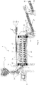
- FIG. 1 shows a system for the torrefaction of a biomass (1) comprising a torrefaction reactor (2) having a biomass inlet (3) and a biomass outlet (4).
- the biomass is predried to a moisture content of about 5 % (w/w) prior to feeding the biomass in to the torrefaction reactor (2) via rotary vane feeders (5).
- the moisture content in the biomass is controlled by a moisture probe (6).
- the temperature of the biomass is about 100 °C.
- the biomass is transported through the torrefaction reactor (2) by means of a transport screw (7) which comprises helicoidal material transport device fixed to a central shaft (7).
- the speed of the biomass transport is regulated by the rotational speed of the transport screw (7) which is driven by a transport screw engine (8).
- An oxygen containing gas is injected to the torrefaction reaction via a gas inlet for injection of an oxygen containing gas (9, 10, 11, 12).
- the oxygen containing gas inlets (13, 14, 15, 16) are connected to valves (17) which controls the supply of oxygen-containing gas to the torrefaction reactor (2).
- a source of the oxygen-containing gas (9, 10, 11, 12) is connected to the oxygen supply means.
- the injected oxygen containing gas reacts with gases released from the biomass during the heating or torrefaction stage. When the gases oxidize, heat is released to the surrounding gas and the material to be torrefied, thereby increasing the temperature.
- Gases given of from the biomass during the torrefaction process are withdrawn at an outlet for torrefaction gases (18). Thereby the torrefaction gases will be transported countercurrent in relation to the transport direction of the biomass.
- the upper arrow (19) in the figure indicates the transport direction of the torrefaction gases while the lower arrow (20) indicates the transport direction of the biomass.
- the temperature in the torrefaction reactor will be highest in the downstream part of the reactor where the oxygen is injected and the temperature will gradually decrease as the hot gases are drawn countercurrent with the biomass transport towards the upstream part of the reactor (2). Thereby the torrefaction gases are condensing on the colder material in the upstream part of the torrefaction reactor (2).
- Some oxygen may be injected through an inlet (16) close to or within the torrefaction gas exit (18) to increase the gas temperature above the dew point to avoid condensation close to or within the gas exit (18), thus partly, or completely eliminating the need for external heating of the gas duct/channel connected to the gas exit (18).
- the biomass exits the torrefacttion reactor (2) via the biomass outlet (4) and is thereafter quench cooled in a water application device (21).
- the torrefied material that has passed the water application device (21) is fed to a first screw cooler (22) for further cooling the torrefied material together with torrefaction gases such that components of the torrefaction gases condenses in the screw cooler (22), e.g. on the torrefied material.
- Part of remaining torrefaction gases can be sucked through and withdrawn from the screw cooler (22) by means of a fan (23) and transferred back to the biomass outlet (4).
- the torrefied material can be further cooled in a second screw cooler (24) and cold torrefied material having a temperature below 100 °C exits the system for the torrefaction of a biomass (1) via a second screw cooler biomass outlet (25).
- IR-thermometers (26, 27, 28) for measuring the surface temperature of the torrefied material are located upstream of the screw coolers (22,24).
- the energy needed for milling a fine powder from the torrefied material, produced using the counter current oxygen enhanced torrefaction method described above is about 2.6 times less (-62%) than the energy needed for milling a torrefied material which have been torrefied using the reference method described above and having the same energy yield.
- Table 1 CC-OET change compared to reference (conventional method). Reference experiments are selected on three different basis; A, B and C. CC-OET experiments are the same for A, B and C. The reference experiments are not the same for A, B and C.
- the energy yield for a biomass, produced using the counter-current oxygen enhanced torrefaction method described above is about 5 % higher than the energy yield of the reference biomass being torrefied to the same torrefaction degree by the reference method described above.
- the heating value in the torrefaction process for a biomass torrefied by the method according to the present invention is about 5 % higher than the biomass torrefied using the reference method at the same energy yield.
- the heating value in the torrefaction process for a biomass torrefied by the method according to the present invention is about 2 % higher than the biomass torrefied using the reference method at the same torrefaction degree.
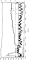
- Figure 2a shows that the temperature of the biomass can be kept stable using the method according to the present invention.
- a wood mixture was torrefied at a biomass surface temperature of about 338°C with countercurrent gas flow during injection of air and 7.5 minutes residence time.
- the x-axis shows the time in hours:minutes
- the left y-axis shows the temperature
- the right y-axis shows the lambda value.
- Curve (1) shows the biomass surface exit temperature
- curve (2) shows the corresponding lambda value
- curve (3-7) shows the gas temperatures in the centre of the torrefaction drum, where (3) is closest to the biomass inlet and (7) is closest to the biomass exit.
- Figure 2b shows the combustibility of the torrefaction generated gas during torrefaction of the wood mixture at 338°C biomass surface temperature with countercurrent gas flow during injection of air and 7.5 minutes residence time. At time 12:00 the process was determined to be at steady-state.
- the x-axis shows the time in hours:minutes.
- the left y-axis shows the temperature and flow in normal litre per minute.
- the right y-axis shows the lambda value*10 ⁇ 3, effect in kW and oxygen partial pressure in %.
- Curve (1) shows the biomass surface exit temperature
- curve (2) shows the corresponding lambda value
- curve (3) shows the surface temperature in the beginning of the gas burner
- curve (4) shows effect in kW of the electrical heater around the gas burner
- curve (5) shows the oxygen content in the flue gases after the gas burner
- curve (6) shows the combustion air flow in normal liters per minute into the gas burner. This demonstrates that the gas withdrawn from the reactor in the method described above is suitable for combustion.
Landscapes
- Chemical & Material Sciences (AREA)
- Engineering & Computer Science (AREA)
- Oil, Petroleum & Natural Gas (AREA)
- Organic Chemistry (AREA)
- Life Sciences & Earth Sciences (AREA)
- Mechanical Engineering (AREA)
- General Engineering & Computer Science (AREA)
- Combustion & Propulsion (AREA)
- Sustainable Development (AREA)
- Thermal Sciences (AREA)
- Physics & Mathematics (AREA)
- Environmental & Geological Engineering (AREA)
- General Life Sciences & Earth Sciences (AREA)
- Geochemistry & Mineralogy (AREA)
- Geology (AREA)
- Processing Of Solid Wastes (AREA)
- Solid Fuels And Fuel-Associated Substances (AREA)
Claims (10)
- Procédé de torréfaction d'une biomasse dans un réacteur de torréfaction de sorte que la biomasse torréfiée et des gaz de torréfaction sont obtenus,
et dans lequel une quantité contrôlée d'un gaz contenant de l'oxygène est apportée au réacteur de torréfaction au niveau d'une première position dans le réacteur de sorte que la valeur lambda soit dans la plage comprise entre 0,001 et 0,1 et que l'oxygène réagisse avec des composants des gaz de torréfaction sous la formation de chaleur
et dans lequel les gaz de torréfaction sont retirés du réacteur torréfaction au niveau d'une seconde position du réacteur de torréfaction
dans lequel la première position est située en aval de la seconde position par rapport à une direction de transport de biomasse dans le réacteur de torréfaction de sorte que les gaz de torréfaction se déplacent à contre-courant dans le réacteur de torréfaction par rapport au transport de biomasse
et dans lequel la biomasse a une température comprise entre 30 °C et 230 °C lors de son entrée dans le réacteur de torréfaction et
dans lequel la température de la biomasse au niveau de la première position dans le réacteur de torréfaction est au moins 50 °C plus élevée que la température de la biomasse dans la seconde position située en amont de la première position dans le réacteur de torréfaction. - Procédé selon la revendication 1, comprenant en outre une étape de broyage de la biomasse torréfiée obtenue de sorte qu'une biomasse torréfiée pulvérisée soit obtenue.
- Procédé selon l'une quelconque des revendications précédentes, dans lequel le gaz contenant de l'oxygène est de l'air enrichi en oxygène.
- Procédé selon la revendication 2, dans lequel la biomasse torréfiée pulvérisée comprend des particules ayant un diamètre moyen inférieur à 1 000 microns.
- Procédé selon la revendication 2 ou la revendication 4, comprenant en outre une étape d'ajout d'un liquide à la biomasse torréfiée pulvérisée afin d'obtenir une boue ou une pâte qui peut être extrudée ayant une concentration comprise entre 40 % (en poids) et 80 % (en poids) de biomasse torréfiée solide.
- Procédé selon la revendication 5, dans lequel le liquide est principalement constitué d'eau et dans lequel la boue obtenue ou la pâte pouvant être extrudée a une concentration comprise entre 70 % (en poids) et 80 % (en poids) de biomasse torréfiée solide.
- Procédé selon l'une quelconque des revendications précédentes, dans lequel la biomasse introduite au niveau de l'entrée du réacteur de torréfaction a une température inférieure à 225 °C.
- Procédé selon l'une quelconque des revendications précédentes, dans lequel la biomasse introduite au niveau de l'entrée du réacteur de torréfaction a une température comprise entre 50 °C et 200 °C.
- Procédé selon l'une quelconque des revendications précédentes, dans lequel une partie des gaz de torréfaction se condense sur la biomasse dans le réacteur de torréfaction tandis que les gaz de torréfaction se déplacent à contre-courant dans le réacteur de torréfaction par rapport au transport de la biomasse.
- Procédé selon l'une quelconque des revendications précédentes, dans lequel la biomasse est la biomasse lignocellulosique.
Applications Claiming Priority (6)
| Application Number | Priority Date | Filing Date | Title |
|---|---|---|---|
| SE1150463 | 2011-05-18 | ||
| SE1150465A SE1150465A1 (sv) | 2011-05-18 | 2011-05-18 | Torrefieringsmetod innefattande att torrefieringsreaktionen kyls för att åtminstone delvis motverka en temperaturhöjning |
| SE1150464 | 2011-05-18 | ||
| SE1150462 | 2011-05-18 | ||
| SE1151062 | 2011-11-10 | ||
| PCT/SE2012/050534 WO2012158118A1 (fr) | 2011-05-18 | 2012-05-16 | Torréfaction améliorée par introduction d'oxygène à contre-courant |
Publications (3)
| Publication Number | Publication Date |
|---|---|
| EP2710097A1 EP2710097A1 (fr) | 2014-03-26 |
| EP2710097A4 EP2710097A4 (fr) | 2014-10-08 |
| EP2710097B1 true EP2710097B1 (fr) | 2019-12-11 |
Family
ID=47177203
Family Applications (1)
| Application Number | Title | Priority Date | Filing Date |
|---|---|---|---|
| EP12785686.2A Active EP2710097B1 (fr) | 2011-05-18 | 2012-05-16 | Torréfaction améliorée par introduction d'oxygène à contre-courant |
Country Status (7)
| Country | Link |
|---|---|
| US (1) | US9580665B2 (fr) |
| EP (1) | EP2710097B1 (fr) |
| CN (1) | CN103608438B (fr) |
| BR (1) | BR112013029478A2 (fr) |
| CA (1) | CA2834324C (fr) |
| RU (1) | RU2623225C2 (fr) |
| WO (1) | WO2012158118A1 (fr) |
Cited By (1)
| Publication number | Priority date | Publication date | Assignee | Title |
|---|---|---|---|---|
| CN109737702A (zh) * | 2019-01-25 | 2019-05-10 | 王金玉 | 一种高效环保的生物质脱水处理设备 |
Families Citing this family (20)
| Publication number | Priority date | Publication date | Assignee | Title |
|---|---|---|---|---|
| US10377954B2 (en) * | 2010-11-09 | 2019-08-13 | Board Of Regents Of The Nevada System Of Higher Education, On Behalf Of The University Of Nevada, Reno | Method for wet torrefaction of a biomass |
| WO2012167796A1 (fr) * | 2011-06-10 | 2012-12-13 | Danmarks Tekniske Universitet | Torréfaction et pyrolyse partielle de matériau pour la production de pastilles combustibles |
| EP2765178A1 (fr) * | 2013-02-07 | 2014-08-13 | Arbaflame Technology AS | Procédé de production de matériau de biomasse enrichie en carbone |
| CN104560259B (zh) * | 2015-01-30 | 2017-04-05 | 湖南大学 | 生物质成型颗粒燃料的制备方法及系统 |
| NL2014279B1 (en) * | 2015-02-12 | 2016-10-13 | Blackwood Tech B V | Cooling process of torrefied biomass. |
| KR20170138077A (ko) * | 2015-03-10 | 2017-12-14 | 엔지누이티 월드와이드, 엘엘씨 | 전처리 및 환류 응축기를 포함하는 바이오매스 장치 및 방법 |
| CN104764020B (zh) * | 2015-04-04 | 2018-04-03 | 北京德美高科科技有限责任公司 | 一种石油钻采固废燃烧处理系统和方法 |
| US10167428B2 (en) * | 2015-06-01 | 2019-01-01 | Central Michigan University | Methods for biomass torrefaction with carbon dioxide capture |
| EP3280786A1 (fr) | 2015-06-15 | 2018-02-14 | Van Exel, Roland Alexander | Procédé amélioré de traitement thermochimique de biomasse à l'aide de l'application régulée d'oxygène |
| US11339342B2 (en) | 2017-05-16 | 2022-05-24 | Massachusetts Institute Of Technology | Biomass conversion reactors and associated systems and methods |
| FR3068708B1 (fr) * | 2017-07-07 | 2020-09-18 | Ifp Energies Now | Procede de traitement de la biomasse par co-broyage avec une charge fossile |
| DK3771740T3 (da) * | 2019-07-31 | 2023-05-01 | Ceg Tech Uk Limited | Fremgangsmåde og apparat til en indtørringsproces |
| EP3771739A1 (fr) * | 2019-07-31 | 2021-02-03 | CEG Technology UK Limited | Procédé et appareil de traitement à sec de charbon et de coke à chaud |
| WO2021115807A1 (fr) * | 2019-12-10 | 2021-06-17 | Basf Se | Processus de pyrolyse d'hydrocarbures dans un réacteur à tambour rotatif indirectement chauffé |
| TWI860477B (zh) * | 2020-05-18 | 2024-11-01 | 日商Mii股份有限公司 | 真空凍結乾燥裝置及真空凍結乾燥方法 |
| US20230201784A1 (en) * | 2020-05-27 | 2023-06-29 | Takachar Lmited | System and method for a multi-chamber biomass reactor |
| CN112226261B (zh) * | 2020-10-12 | 2021-06-04 | 新宁新欣热能科技有限公司 | 一种生物颗粒燃料生产方法 |
| AU2021203638A1 (en) * | 2021-06-03 | 2022-12-22 | Earth Systems Consulting Pty. Ltd. | Continuous process pyrolysis sytem |
| JP7085088B1 (ja) * | 2021-08-03 | 2022-06-16 | 株式会社エムアイアイ | 凍結乾燥物 |
| CN115368924B (zh) * | 2022-09-07 | 2023-11-03 | 河南省科学院 | 一种大型生物质烘焙炉进料系统 |
Citations (2)
| Publication number | Priority date | Publication date | Assignee | Title |
|---|---|---|---|---|
| US20090084029A1 (en) * | 2006-01-06 | 2009-04-02 | Stichting Energieonderzoek Centrum Nederland | Process and device for treating biomass |
| WO2013028361A1 (fr) * | 2011-08-23 | 2013-02-28 | Advanced Torrefaction Systems, Llc | Systèmes et procédés de torréfaction comprenant une oxydation catalytique et/ou une réutilisation des gaz de combustion directement dans un réacteur de torréfaction, refroidisseur, et/ou séchoir/préchauffeur |
Family Cites Families (46)
| Publication number | Priority date | Publication date | Assignee | Title |
|---|---|---|---|---|
| US3501380A (en) | 1968-12-30 | 1970-03-17 | Koppers Co Inc | Method and apparatus for measuring the temperature of coke oven walls |
| US3888621A (en) | 1974-04-12 | 1975-06-10 | Alcan Res & Dev | Monitoring and controlling kiln operation in calcination of coke |
| JPS51114976A (en) | 1975-04-02 | 1976-10-09 | Jeol Ltd | Observation-window contamination detector |
| JPS51115205A (en) | 1975-04-02 | 1976-10-09 | Jeol Ltd | Furnace top observation unit |
| JPS5542058A (en) | 1978-09-20 | 1980-03-25 | Sumitomo Metal Ind Ltd | Method of measuring temperature in furnace |
| US4344819A (en) | 1980-06-23 | 1982-08-17 | Bethlehem Steel Corporation | Method of determining coke level |
| DE3041627A1 (de) | 1980-11-05 | 1982-06-09 | Artur Richard 6000 Frankfurt Greul | Verfahren zum aufarbeiten von zellulosehaltigen biomassen bzw. braunkohle und lignit zu einem einheitlichenk stark reaktionsfaehigen, staubfoermigen brennstoff |
| ZA828269B (en) | 1981-12-08 | 1983-09-28 | Bethlehem Steel Corp | Method and system for determining mass temperature in the hostile environment |
| US5017269A (en) | 1988-12-28 | 1991-05-21 | Apv Chemical Machinery Inc. | Method of continuously carbonizing primarily organic waste material |
| SE500058C2 (sv) | 1991-04-05 | 1994-03-28 | Anders Kullendorff | Förfarande för rostning av biomaterial |
| US5728361A (en) | 1995-11-01 | 1998-03-17 | Ferro-Tech Tire Reclamation, Inc. | Method for recovering carbon black from composites |
| BR9902606B1 (pt) * | 1999-06-23 | 2011-04-19 | combustìvel de celulignina catalìtica. | |
| US20030221363A1 (en) | 2002-05-21 | 2003-12-04 | Reed Thomas B. | Process and apparatus for making a densified torrefied fuel |
| US7100303B2 (en) | 2002-11-20 | 2006-09-05 | Pci Industries Inc. | Apparatus and method for the heat treatment of lignocellulosic material |
| UA84185C2 (ru) | 2003-12-12 | 2008-09-25 | Коултек Корпорейшн | Способ и установка для обработки сырового твердого топлива |
| NL1025027C2 (nl) * | 2003-12-15 | 2005-06-21 | Stichting Energie | Werkwijze en stelsel voor de productie van vaste stoffen uit grondstoffen. |
| CA2482571A1 (fr) | 2004-09-27 | 2006-03-27 | 9103-7366 Quebec Inc. | Appareil pour le traitement de materiaux lignocellulosiques, et methode de traitement connexe |
| DE102005038135B3 (de) | 2005-08-11 | 2007-03-08 | Schottdorf, Bernd, Dr. | Vorrichtung und Verfahren zur kontinuierlichen Herstellung von Holzkohle |
| FR2910488B1 (fr) | 2006-12-20 | 2010-06-04 | Inst Francais Du Petrole | Procede de conversion de biomasse pour la production de gaz de synthese. |
| DE102007056170A1 (de) | 2006-12-28 | 2008-11-06 | Dominik Peus | Semikontinuierliches Verfahren zur Herstellung von Brennstoff aus Biomasse |
| US20090007484A1 (en) | 2007-02-23 | 2009-01-08 | Smith David G | Apparatus and process for converting biomass feed materials into reusable carbonaceous and hydrocarbon products |
| GB2448531B (en) * | 2007-04-19 | 2012-02-08 | Coal Products Ltd | Fuel briquette |
| BRPI0911367B1 (pt) | 2008-04-03 | 2020-01-07 | North Carolina State University | Dispositivo e processo de torrefação autotérmico de biomassa, método para aumentar a efetividade de custo no uso da mesma como combustível e processo para produzir péletes de biomassa torrada |
| SE532746C2 (sv) * | 2008-06-11 | 2010-03-30 | Bio Energy Dev North Ab | Förfarande och apparatur för framställning av torrefierat lignocellulosamaterial |
| EP2318487B1 (fr) | 2008-07-04 | 2019-05-01 | University of York | Torréfaction de biomasse sous micro-ondes |
| US8161663B2 (en) | 2008-10-03 | 2012-04-24 | Wyssmont Co. Inc. | System and method for drying and torrefaction |
| US8669404B2 (en) | 2008-10-15 | 2014-03-11 | Renewable Fuel Technologies, Inc. | Method for conversion of biomass to biofuel |
| US8465627B2 (en) * | 2008-11-28 | 2013-06-18 | Kior, Inc. | Comminution and densification of biomass particles |
| EP2373762A1 (fr) | 2008-12-08 | 2011-10-12 | Foxcoal IP B.V. | Procédé de fabrication de papier |
| WO2010089342A1 (fr) * | 2009-02-04 | 2010-08-12 | Shell Internationale Research Maatschappij B.V. | Procédé de conversion de la biomasse |
| WO2010102145A1 (fr) | 2009-03-04 | 2010-09-10 | Washington State University | Systèmes et procédés de production de biocombustibles à partir de matières lignocellulosiques |
| WO2010099626A1 (fr) * | 2009-03-05 | 2010-09-10 | G4 Insights Inc. | Processus et système de transformation thermochimique de la biomasse |
| US8276289B2 (en) * | 2009-03-27 | 2012-10-02 | Terra Green Energy, Llc | System and method for preparation of solid biomass by torrefaction |
| US20100273899A1 (en) | 2009-04-22 | 2010-10-28 | Range Fuels, Inc. | Integrated, high-efficiency processes for biomass conversion to synthesis gas |
| US8668753B2 (en) * | 2009-04-24 | 2014-03-11 | G.D.O. Inc | Two stage process for converting biomass to syngas |
| FI20090183A0 (fi) * | 2009-05-08 | 2009-05-08 | Markku Olavi Raiko | Menetelmä biomassan termiseksi käsittelemiseksi lämpökattilan yhteydessä |
| GB0908082D0 (en) | 2009-05-11 | 2009-06-24 | Univ Aston | Biomass pyrolysis |
| US20120125064A1 (en) | 2009-05-15 | 2012-05-24 | Stephen David Joseph | Biochar complex |
| FR2948448B1 (fr) | 2009-07-21 | 2014-01-10 | Inst Francais Du Petrole | Four tournant pour traitement thermique radiatif de materiaux solides |
| US8449724B2 (en) * | 2009-08-19 | 2013-05-28 | Andritz Technology And Asset Management Gmbh | Method and system for the torrefaction of lignocellulosic material |
| EP2545146A4 (fr) | 2010-03-08 | 2014-05-07 | Arthur M Shulenberger | Dispositif et procédé pour la conversion de la biomasse en biocarburant |
| WO2011119470A1 (fr) | 2010-03-22 | 2011-09-29 | Ber Technology Company Llc | Système et procédé de torréfaction et de traitement de biomasse |
| SE534630C2 (sv) | 2010-03-29 | 2011-11-01 | Torkapp R Termisk Processutrustning Ab | Metod och anordning för torrefiering av biomassa |
| US20110252698A1 (en) | 2010-04-20 | 2011-10-20 | River Basin Energy, Inc. | Method of Drying Biomass |
| US8956426B2 (en) | 2010-04-20 | 2015-02-17 | River Basin Energy, Inc. | Method of drying biomass |
| KR101012861B1 (ko) * | 2010-04-28 | 2011-02-08 | 한국전력공사 | 미분탄 보일러용 연료 전처리 시스템 |
-
2012
- 2012-05-16 US US14/123,602 patent/US9580665B2/en not_active Expired - Fee Related
- 2012-05-16 CA CA2834324A patent/CA2834324C/fr active Active
- 2012-05-16 CN CN201280029970.3A patent/CN103608438B/zh not_active Expired - Fee Related
- 2012-05-16 RU RU2013156039A patent/RU2623225C2/ru active
- 2012-05-16 WO PCT/SE2012/050534 patent/WO2012158118A1/fr not_active Ceased
- 2012-05-16 EP EP12785686.2A patent/EP2710097B1/fr active Active
- 2012-05-16 BR BR112013029478-7A patent/BR112013029478A2/pt not_active Application Discontinuation
Patent Citations (2)
| Publication number | Priority date | Publication date | Assignee | Title |
|---|---|---|---|---|
| US20090084029A1 (en) * | 2006-01-06 | 2009-04-02 | Stichting Energieonderzoek Centrum Nederland | Process and device for treating biomass |
| WO2013028361A1 (fr) * | 2011-08-23 | 2013-02-28 | Advanced Torrefaction Systems, Llc | Systèmes et procédés de torréfaction comprenant une oxydation catalytique et/ou une réutilisation des gaz de combustion directement dans un réacteur de torréfaction, refroidisseur, et/ou séchoir/préchauffeur |
Cited By (2)
| Publication number | Priority date | Publication date | Assignee | Title |
|---|---|---|---|---|
| CN109737702A (zh) * | 2019-01-25 | 2019-05-10 | 王金玉 | 一种高效环保的生物质脱水处理设备 |
| CN109737702B (zh) * | 2019-01-25 | 2020-10-23 | 浏阳市鑫利粉末冶金有限公司 | 一种高效环保的生物质脱水处理设备 |
Also Published As
| Publication number | Publication date |
|---|---|
| CN103608438A (zh) | 2014-02-26 |
| EP2710097A4 (fr) | 2014-10-08 |
| RU2623225C2 (ru) | 2017-06-23 |
| EP2710097A1 (fr) | 2014-03-26 |
| CA2834324C (fr) | 2019-11-26 |
| US9580665B2 (en) | 2017-02-28 |
| RU2013156039A (ru) | 2015-06-27 |
| CN103608438B (zh) | 2016-08-31 |
| CA2834324A1 (fr) | 2012-11-22 |
| WO2012158118A1 (fr) | 2012-11-22 |
| BR112013029478A2 (pt) | 2020-08-04 |
| US20140208995A1 (en) | 2014-07-31 |
Similar Documents
| Publication | Publication Date | Title |
|---|---|---|
| EP2710097B1 (fr) | Torréfaction améliorée par introduction d'oxygène à contre-courant | |
| US7833512B2 (en) | Production of synthesis gas from biomass and any organic matter by reactive contact with superheated steam | |
| NL2019553B1 (en) | Process to prepare an activated carbon product and a syngas mixture | |
| EP2430122B1 (fr) | Procédé de traitement thermique d'une biomasse en relation avec une installation de chauffage | |
| US11994070B2 (en) | Systems and methods for processing carbonaceous feedstock | |
| RU2395559C1 (ru) | Способ термической переработки органосодержащего сырья | |
| Zhu et al. | Flue gas torrefaction of distilled spirit lees and the effects on the combustion and nitrogen oxide emission | |
| JP2020534426A (ja) | チャー生成物及び合成ガス混合物を調製する方法 | |
| US10584296B2 (en) | Method and system for energy efficient torrefaction of biomass | |
| SE538488C2 (en) | Method for thermal treatment of raw materials comprising lignocellulose | |
| EP2236588A1 (fr) | Procédé pour l'utilisation d'eau de pyrolyse | |
| EP2247695B1 (fr) | Procédé et appareil pour convertir la biomasse et toute autre matière organique en gaz énergétiques utiles | |
| Pandey et al. | Tar cracking enhancement by air sparger installation in the combustion zone of the downdraft gasifier | |
| CN200992537Y (zh) | 一种固体生物质内燃式低压热裂解气化炉 | |
| CN104152182A (zh) | 一种生物质气化发电的方法 | |
| KR101519528B1 (ko) | 바이오매스로부터 합성가스를 제조하는 방법 및 장치 | |
| Piętak et al. | Possibilities of supplying internal combustion engines by wood gas | |
| EP3280786A1 (fr) | Procédé amélioré de traitement thermochimique de biomasse à l'aide de l'application régulée d'oxygène | |
| RU2378319C1 (ru) | Способ получения углеводородного топлива и углеродных материалов из биомассы | |
| Murray | Production of high value solid fuels from cellulosic feed materials by the Koppelman process | |
| WO2012158115A2 (fr) | Élimination de l'humidité dans une étape de préséchage au cours d'un processus de torréfaction |
Legal Events
| Date | Code | Title | Description |
|---|---|---|---|
| PUAI | Public reference made under article 153(3) epc to a published international application that has entered the european phase |
Free format text: ORIGINAL CODE: 0009012 |
|
| 17P | Request for examination filed |
Effective date: 20131022 |
|
| AK | Designated contracting states |
Kind code of ref document: A1 Designated state(s): AL AT BE BG CH CY CZ DE DK EE ES FI FR GB GR HR HU IE IS IT LI LT LU LV MC MK MT NL NO PL PT RO RS SE SI SK SM TR |
|
| DAX | Request for extension of the european patent (deleted) | ||
| A4 | Supplementary search report drawn up and despatched |
Effective date: 20140908 |
|
| RIC1 | Information provided on ipc code assigned before grant |
Ipc: C10L 9/08 20060101AFI20140902BHEP |
|
| 17Q | First examination report despatched |
Effective date: 20160225 |
|
| STAA | Information on the status of an ep patent application or granted ep patent |
Free format text: STATUS: EXAMINATION IS IN PROGRESS |
|
| GRAP | Despatch of communication of intention to grant a patent |
Free format text: ORIGINAL CODE: EPIDOSNIGR1 |
|
| STAA | Information on the status of an ep patent application or granted ep patent |
Free format text: STATUS: GRANT OF PATENT IS INTENDED |
|
| INTG | Intention to grant announced |
Effective date: 20190726 |
|
| GRAS | Grant fee paid |
Free format text: ORIGINAL CODE: EPIDOSNIGR3 |
|
| GRAA | (expected) grant |
Free format text: ORIGINAL CODE: 0009210 |
|
| STAA | Information on the status of an ep patent application or granted ep patent |
Free format text: STATUS: THE PATENT HAS BEEN GRANTED |
|
| AK | Designated contracting states |
Kind code of ref document: B1 Designated state(s): AL AT BE BG CH CY CZ DE DK EE ES FI FR GB GR HR HU IE IS IT LI LT LU LV MC MK MT NL NO PL PT RO RS SE SI SK SM TR |
|
| REG | Reference to a national code |
Ref country code: GB Ref legal event code: FG4D |
|
| REG | Reference to a national code |
Ref country code: CH Ref legal event code: EP |
|
| REG | Reference to a national code |
Ref country code: AT Ref legal event code: REF Ref document number: 1212186 Country of ref document: AT Kind code of ref document: T Effective date: 20191215 |
|
| REG | Reference to a national code |
Ref country code: DE Ref legal event code: R096 Ref document number: 602012066413 Country of ref document: DE |
|
| REG | Reference to a national code |
Ref country code: IE Ref legal event code: FG4D |
|
| REG | Reference to a national code |
Ref country code: SE Ref legal event code: TRGR |
|
| REG | Reference to a national code |
Ref country code: NL Ref legal event code: FP |
|
| REG | Reference to a national code |
Ref country code: LT Ref legal event code: MG4D |
|
| PG25 | Lapsed in a contracting state [announced via postgrant information from national office to epo] |
Ref country code: GR Free format text: LAPSE BECAUSE OF FAILURE TO SUBMIT A TRANSLATION OF THE DESCRIPTION OR TO PAY THE FEE WITHIN THE PRESCRIBED TIME-LIMIT Effective date: 20200312 Ref country code: NO Free format text: LAPSE BECAUSE OF FAILURE TO SUBMIT A TRANSLATION OF THE DESCRIPTION OR TO PAY THE FEE WITHIN THE PRESCRIBED TIME-LIMIT Effective date: 20200311 Ref country code: BG Free format text: LAPSE BECAUSE OF FAILURE TO SUBMIT A TRANSLATION OF THE DESCRIPTION OR TO PAY THE FEE WITHIN THE PRESCRIBED TIME-LIMIT Effective date: 20200311 Ref country code: LV Free format text: LAPSE BECAUSE OF FAILURE TO SUBMIT A TRANSLATION OF THE DESCRIPTION OR TO PAY THE FEE WITHIN THE PRESCRIBED TIME-LIMIT Effective date: 20191211 Ref country code: FI Free format text: LAPSE BECAUSE OF FAILURE TO SUBMIT A TRANSLATION OF THE DESCRIPTION OR TO PAY THE FEE WITHIN THE PRESCRIBED TIME-LIMIT Effective date: 20191211 Ref country code: ES Free format text: LAPSE BECAUSE OF FAILURE TO SUBMIT A TRANSLATION OF THE DESCRIPTION OR TO PAY THE FEE WITHIN THE PRESCRIBED TIME-LIMIT Effective date: 20191211 Ref country code: LT Free format text: LAPSE BECAUSE OF FAILURE TO SUBMIT A TRANSLATION OF THE DESCRIPTION OR TO PAY THE FEE WITHIN THE PRESCRIBED TIME-LIMIT Effective date: 20191211 |
|
| PG25 | Lapsed in a contracting state [announced via postgrant information from national office to epo] |
Ref country code: HR Free format text: LAPSE BECAUSE OF FAILURE TO SUBMIT A TRANSLATION OF THE DESCRIPTION OR TO PAY THE FEE WITHIN THE PRESCRIBED TIME-LIMIT Effective date: 20191211 Ref country code: RS Free format text: LAPSE BECAUSE OF FAILURE TO SUBMIT A TRANSLATION OF THE DESCRIPTION OR TO PAY THE FEE WITHIN THE PRESCRIBED TIME-LIMIT Effective date: 20191211 |
|
| PG25 | Lapsed in a contracting state [announced via postgrant information from national office to epo] |
Ref country code: AL Free format text: LAPSE BECAUSE OF FAILURE TO SUBMIT A TRANSLATION OF THE DESCRIPTION OR TO PAY THE FEE WITHIN THE PRESCRIBED TIME-LIMIT Effective date: 20191211 |
|
| REG | Reference to a national code |
Ref country code: EE Ref legal event code: FG4A Ref document number: E019194 Country of ref document: EE Effective date: 20200416 |
|
| PG25 | Lapsed in a contracting state [announced via postgrant information from national office to epo] |
Ref country code: CZ Free format text: LAPSE BECAUSE OF FAILURE TO SUBMIT A TRANSLATION OF THE DESCRIPTION OR TO PAY THE FEE WITHIN THE PRESCRIBED TIME-LIMIT Effective date: 20191211 Ref country code: RO Free format text: LAPSE BECAUSE OF FAILURE TO SUBMIT A TRANSLATION OF THE DESCRIPTION OR TO PAY THE FEE WITHIN THE PRESCRIBED TIME-LIMIT Effective date: 20191211 Ref country code: PT Free format text: LAPSE BECAUSE OF FAILURE TO SUBMIT A TRANSLATION OF THE DESCRIPTION OR TO PAY THE FEE WITHIN THE PRESCRIBED TIME-LIMIT Effective date: 20200506 |
|
| PG25 | Lapsed in a contracting state [announced via postgrant information from national office to epo] |
Ref country code: SM Free format text: LAPSE BECAUSE OF FAILURE TO SUBMIT A TRANSLATION OF THE DESCRIPTION OR TO PAY THE FEE WITHIN THE PRESCRIBED TIME-LIMIT Effective date: 20191211 Ref country code: IS Free format text: LAPSE BECAUSE OF FAILURE TO SUBMIT A TRANSLATION OF THE DESCRIPTION OR TO PAY THE FEE WITHIN THE PRESCRIBED TIME-LIMIT Effective date: 20200411 Ref country code: SK Free format text: LAPSE BECAUSE OF FAILURE TO SUBMIT A TRANSLATION OF THE DESCRIPTION OR TO PAY THE FEE WITHIN THE PRESCRIBED TIME-LIMIT Effective date: 20191211 |
|
| REG | Reference to a national code |
Ref country code: DE Ref legal event code: R097 Ref document number: 602012066413 Country of ref document: DE |
|
| REG | Reference to a national code |
Ref country code: AT Ref legal event code: MK05 Ref document number: 1212186 Country of ref document: AT Kind code of ref document: T Effective date: 20191211 |
|
| PLBE | No opposition filed within time limit |
Free format text: ORIGINAL CODE: 0009261 |
|
| STAA | Information on the status of an ep patent application or granted ep patent |
Free format text: STATUS: NO OPPOSITION FILED WITHIN TIME LIMIT |
|
| PG25 | Lapsed in a contracting state [announced via postgrant information from national office to epo] |
Ref country code: DK Free format text: LAPSE BECAUSE OF FAILURE TO SUBMIT A TRANSLATION OF THE DESCRIPTION OR TO PAY THE FEE WITHIN THE PRESCRIBED TIME-LIMIT Effective date: 20191211 |
|
| 26N | No opposition filed |
Effective date: 20200914 |
|
| PG25 | Lapsed in a contracting state [announced via postgrant information from national office to epo] |
Ref country code: AT Free format text: LAPSE BECAUSE OF FAILURE TO SUBMIT A TRANSLATION OF THE DESCRIPTION OR TO PAY THE FEE WITHIN THE PRESCRIBED TIME-LIMIT Effective date: 20191211 Ref country code: SI Free format text: LAPSE BECAUSE OF FAILURE TO SUBMIT A TRANSLATION OF THE DESCRIPTION OR TO PAY THE FEE WITHIN THE PRESCRIBED TIME-LIMIT Effective date: 20191211 Ref country code: PL Free format text: LAPSE BECAUSE OF FAILURE TO SUBMIT A TRANSLATION OF THE DESCRIPTION OR TO PAY THE FEE WITHIN THE PRESCRIBED TIME-LIMIT Effective date: 20191211 |
|
| PG25 | Lapsed in a contracting state [announced via postgrant information from national office to epo] |
Ref country code: LI Free format text: LAPSE BECAUSE OF NON-PAYMENT OF DUE FEES Effective date: 20200531 Ref country code: IT Free format text: LAPSE BECAUSE OF FAILURE TO SUBMIT A TRANSLATION OF THE DESCRIPTION OR TO PAY THE FEE WITHIN THE PRESCRIBED TIME-LIMIT Effective date: 20191211 Ref country code: CH Free format text: LAPSE BECAUSE OF NON-PAYMENT OF DUE FEES Effective date: 20200531 Ref country code: MC Free format text: LAPSE BECAUSE OF FAILURE TO SUBMIT A TRANSLATION OF THE DESCRIPTION OR TO PAY THE FEE WITHIN THE PRESCRIBED TIME-LIMIT Effective date: 20191211 |
|
| PG25 | Lapsed in a contracting state [announced via postgrant information from national office to epo] |
Ref country code: LU Free format text: LAPSE BECAUSE OF NON-PAYMENT OF DUE FEES Effective date: 20200516 |
|
| PG25 | Lapsed in a contracting state [announced via postgrant information from national office to epo] |
Ref country code: IE Free format text: LAPSE BECAUSE OF NON-PAYMENT OF DUE FEES Effective date: 20200516 |
|
| PG25 | Lapsed in a contracting state [announced via postgrant information from national office to epo] |
Ref country code: TR Free format text: LAPSE BECAUSE OF FAILURE TO SUBMIT A TRANSLATION OF THE DESCRIPTION OR TO PAY THE FEE WITHIN THE PRESCRIBED TIME-LIMIT Effective date: 20191211 Ref country code: MT Free format text: LAPSE BECAUSE OF FAILURE TO SUBMIT A TRANSLATION OF THE DESCRIPTION OR TO PAY THE FEE WITHIN THE PRESCRIBED TIME-LIMIT Effective date: 20191211 Ref country code: CY Free format text: LAPSE BECAUSE OF FAILURE TO SUBMIT A TRANSLATION OF THE DESCRIPTION OR TO PAY THE FEE WITHIN THE PRESCRIBED TIME-LIMIT Effective date: 20191211 |
|
| PG25 | Lapsed in a contracting state [announced via postgrant information from national office to epo] |
Ref country code: MK Free format text: LAPSE BECAUSE OF FAILURE TO SUBMIT A TRANSLATION OF THE DESCRIPTION OR TO PAY THE FEE WITHIN THE PRESCRIBED TIME-LIMIT Effective date: 20191211 |
|
| PGFP | Annual fee paid to national office [announced via postgrant information from national office to epo] |
Ref country code: FR Payment date: 20220516 Year of fee payment: 11 Ref country code: DE Payment date: 20220519 Year of fee payment: 11 |
|
| REG | Reference to a national code |
Ref country code: DE Ref legal event code: R119 Ref document number: 602012066413 Country of ref document: DE |
|
| PG25 | Lapsed in a contracting state [announced via postgrant information from national office to epo] |
Ref country code: DE Free format text: LAPSE BECAUSE OF NON-PAYMENT OF DUE FEES Effective date: 20231201 |
|
| PG25 | Lapsed in a contracting state [announced via postgrant information from national office to epo] |
Ref country code: FR Free format text: LAPSE BECAUSE OF NON-PAYMENT OF DUE FEES Effective date: 20230531 |
|
| PGFP | Annual fee paid to national office [announced via postgrant information from national office to epo] |
Ref country code: NL Payment date: 20240516 Year of fee payment: 13 |
|
| PGFP | Annual fee paid to national office [announced via postgrant information from national office to epo] |
Ref country code: GB Payment date: 20240517 Year of fee payment: 13 |
|
| PGFP | Annual fee paid to national office [announced via postgrant information from national office to epo] |
Ref country code: BE Payment date: 20240516 Year of fee payment: 13 |
|
| PGFP | Annual fee paid to national office [announced via postgrant information from national office to epo] |
Ref country code: EE Payment date: 20250527 Year of fee payment: 14 |
|
| PGFP | Annual fee paid to national office [announced via postgrant information from national office to epo] |
Ref country code: SE Payment date: 20250520 Year of fee payment: 14 |
|
| REG | Reference to a national code |
Ref country code: NL Ref legal event code: MM Effective date: 20250601 |
|
| GBPC | Gb: european patent ceased through non-payment of renewal fee |
Effective date: 20250516 |
|
| REG | Reference to a national code |
Ref country code: BE Ref legal event code: MM Effective date: 20250531 |
|
| PG25 | Lapsed in a contracting state [announced via postgrant information from national office to epo] |
Ref country code: NL Free format text: LAPSE BECAUSE OF NON-PAYMENT OF DUE FEES Effective date: 20250601 |
|
| PG25 | Lapsed in a contracting state [announced via postgrant information from national office to epo] |
Ref country code: GB Free format text: LAPSE BECAUSE OF NON-PAYMENT OF DUE FEES Effective date: 20250516 |
|
| PG25 | Lapsed in a contracting state [announced via postgrant information from national office to epo] |
Ref country code: BE Free format text: LAPSE BECAUSE OF NON-PAYMENT OF DUE FEES Effective date: 20250531 |