EP2710246B1 - Procédé et dispositif de commande et de régulation d'un système moteur à combustion interne/générateur - Google Patents
Procédé et dispositif de commande et de régulation d'un système moteur à combustion interne/générateur Download PDFInfo
- Publication number
- EP2710246B1 EP2710246B1 EP12724291.5A EP12724291A EP2710246B1 EP 2710246 B1 EP2710246 B1 EP 2710246B1 EP 12724291 A EP12724291 A EP 12724291A EP 2710246 B1 EP2710246 B1 EP 2710246B1
- Authority
- EP
- European Patent Office
- Prior art keywords
- internal combustion
- combustion engine
- load
- operating state
- generator
- Prior art date
- Legal status (The legal status is an assumption and is not a legal conclusion. Google has not performed a legal analysis and makes no representation as to the accuracy of the status listed.)
- Active
Links
Images



Classifications
-
- F—MECHANICAL ENGINEERING; LIGHTING; HEATING; WEAPONS; BLASTING
- F02—COMBUSTION ENGINES; HOT-GAS OR COMBUSTION-PRODUCT ENGINE PLANTS
- F02B—INTERNAL-COMBUSTION PISTON ENGINES; COMBUSTION ENGINES IN GENERAL
- F02B63/00—Adaptations of engines for driving pumps, hand-held tools or electric generators; Portable combinations of engines with engine-driven devices
- F02B63/04—Adaptations of engines for driving pumps, hand-held tools or electric generators; Portable combinations of engines with engine-driven devices for electric generators
-
- B—PERFORMING OPERATIONS; TRANSPORTING
- B60—VEHICLES IN GENERAL
- B60L—PROPULSION OF ELECTRICALLY-PROPELLED VEHICLES; SUPPLYING ELECTRIC POWER FOR AUXILIARY EQUIPMENT OF ELECTRICALLY-PROPELLED VEHICLES; ELECTRODYNAMIC BRAKE SYSTEMS FOR VEHICLES IN GENERAL; MAGNETIC SUSPENSION OR LEVITATION FOR VEHICLES; MONITORING OPERATING VARIABLES OF ELECTRICALLY-PROPELLED VEHICLES; ELECTRIC SAFETY DEVICES FOR ELECTRICALLY-PROPELLED VEHICLES
- B60L50/00—Electric propulsion with power supplied within the vehicle
- B60L50/10—Electric propulsion with power supplied within the vehicle using propulsion power supplied by engine-driven generators, e.g. generators driven by combustion engines
- B60L50/13—Electric propulsion with power supplied within the vehicle using propulsion power supplied by engine-driven generators, e.g. generators driven by combustion engines using AC generators and AC motors
-
- B—PERFORMING OPERATIONS; TRANSPORTING
- B63—SHIPS OR OTHER WATERBORNE VESSELS; RELATED EQUIPMENT
- B63H—MARINE PROPULSION OR STEERING
- B63H21/00—Use of propulsion power plant or units on vessels
- B63H21/21—Control means for engine or transmission, specially adapted for use on marine vessels
-
- B—PERFORMING OPERATIONS; TRANSPORTING
- B63—SHIPS OR OTHER WATERBORNE VESSELS; RELATED EQUIPMENT
- B63J—AUXILIARIES ON VESSELS
- B63J3/00—Driving of auxiliaries
-
- F—MECHANICAL ENGINEERING; LIGHTING; HEATING; WEAPONS; BLASTING
- F02—COMBUSTION ENGINES; HOT-GAS OR COMBUSTION-PRODUCT ENGINE PLANTS
- F02D—CONTROLLING COMBUSTION ENGINES
- F02D25/00—Controlling two or more co-operating engines
-
- F—MECHANICAL ENGINEERING; LIGHTING; HEATING; WEAPONS; BLASTING
- F02—COMBUSTION ENGINES; HOT-GAS OR COMBUSTION-PRODUCT ENGINE PLANTS
- F02D—CONTROLLING COMBUSTION ENGINES
- F02D29/00—Controlling engines, such controlling being peculiar to the devices driven thereby, the devices being other than parts or accessories essential to engine operation, e.g. controlling of engines by signals external thereto
- F02D29/06—Controlling engines, such controlling being peculiar to the devices driven thereby, the devices being other than parts or accessories essential to engine operation, e.g. controlling of engines by signals external thereto peculiar to engines driving electric generators
-
- F—MECHANICAL ENGINEERING; LIGHTING; HEATING; WEAPONS; BLASTING
- F02—COMBUSTION ENGINES; HOT-GAS OR COMBUSTION-PRODUCT ENGINE PLANTS
- F02D—CONTROLLING COMBUSTION ENGINES
- F02D41/00—Electrical control of supply of combustible mixture or its constituents
- F02D41/02—Circuit arrangements for generating control signals
- F02D41/0205—Circuit arrangements for generating control signals using an auxiliary engine speed control
-
- H—ELECTRICITY
- H02—GENERATION; CONVERSION OR DISTRIBUTION OF ELECTRIC POWER
- H02J—ELECTRIC POWER NETWORKS; CIRCUIT ARRANGEMENTS OR SYSTEMS FOR SUPPLYING OR DISTRIBUTING ELECTRIC POWER; SYSTEMS FOR STORING ELECTRIC ENERGY
- H02J4/00—Circuit arrangements for mains or distribution networks not specified as AC or DC; Circuit arrangements for mains or distribution networks combining AC and DC sections or sub-networks
-
- B—PERFORMING OPERATIONS; TRANSPORTING
- B60—VEHICLES IN GENERAL
- B60L—PROPULSION OF ELECTRICALLY-PROPELLED VEHICLES; SUPPLYING ELECTRIC POWER FOR AUXILIARY EQUIPMENT OF ELECTRICALLY-PROPELLED VEHICLES; ELECTRODYNAMIC BRAKE SYSTEMS FOR VEHICLES IN GENERAL; MAGNETIC SUSPENSION OR LEVITATION FOR VEHICLES; MONITORING OPERATING VARIABLES OF ELECTRICALLY-PROPELLED VEHICLES; ELECTRIC SAFETY DEVICES FOR ELECTRICALLY-PROPELLED VEHICLES
- B60L2200/00—Type of vehicles
- B60L2200/32—Waterborne vessels
-
- F—MECHANICAL ENGINEERING; LIGHTING; HEATING; WEAPONS; BLASTING
- F02—COMBUSTION ENGINES; HOT-GAS OR COMBUSTION-PRODUCT ENGINE PLANTS
- F02B—INTERNAL-COMBUSTION PISTON ENGINES; COMBUSTION ENGINES IN GENERAL
- F02B75/00—Other engines
- F02B75/16—Engines characterised by number of cylinders, e.g. single-cylinder engines
-
- F—MECHANICAL ENGINEERING; LIGHTING; HEATING; WEAPONS; BLASTING
- F02—COMBUSTION ENGINES; HOT-GAS OR COMBUSTION-PRODUCT ENGINE PLANTS
- F02B—INTERNAL-COMBUSTION PISTON ENGINES; COMBUSTION ENGINES IN GENERAL
- F02B77/00—Component parts, details or accessories, not otherwise provided for
- F02B77/11—Thermal or acoustic insulation
- F02B77/13—Acoustic insulation
-
- F—MECHANICAL ENGINEERING; LIGHTING; HEATING; WEAPONS; BLASTING
- F02—COMBUSTION ENGINES; HOT-GAS OR COMBUSTION-PRODUCT ENGINE PLANTS
- F02D—CONTROLLING COMBUSTION ENGINES
- F02D41/00—Electrical control of supply of combustible mixture or its constituents
- F02D41/02—Circuit arrangements for generating control signals
- F02D41/14—Introducing closed-loop corrections
- F02D41/1401—Introducing closed-loop corrections characterised by the control or regulation method
- F02D2041/1433—Introducing closed-loop corrections characterised by the control or regulation method using a model or simulation of the system
-
- H—ELECTRICITY
- H02—GENERATION; CONVERSION OR DISTRIBUTION OF ELECTRIC POWER
- H02J—ELECTRIC POWER NETWORKS; CIRCUIT ARRANGEMENTS OR SYSTEMS FOR SUPPLYING OR DISTRIBUTING ELECTRIC POWER; SYSTEMS FOR STORING ELECTRIC ENERGY
- H02J2105/00—Networks for supplying or distributing electric power characterised by their spatial reach or by the load
- H02J2105/30—Networks for supplying or distributing electric power characterised by their spatial reach or by the load the load networks being external to vehicles, i.e. exchanging power with vehicles
- H02J2105/31—Networks for supplying or distributing electric power characterised by their spatial reach or by the load the load networks being external to vehicles, i.e. exchanging power with vehicles for ships or vessels
-
- Y—GENERAL TAGGING OF NEW TECHNOLOGICAL DEVELOPMENTS; GENERAL TAGGING OF CROSS-SECTIONAL TECHNOLOGIES SPANNING OVER SEVERAL SECTIONS OF THE IPC; TECHNICAL SUBJECTS COVERED BY FORMER USPC CROSS-REFERENCE ART COLLECTIONS [XRACs] AND DIGESTS
- Y02—TECHNOLOGIES OR APPLICATIONS FOR MITIGATION OR ADAPTATION AGAINST CLIMATE CHANGE
- Y02T—CLIMATE CHANGE MITIGATION TECHNOLOGIES RELATED TO TRANSPORTATION
- Y02T10/00—Road transport of goods or passengers
- Y02T10/60—Other road transportation technologies with climate change mitigation effect
- Y02T10/70—Energy storage systems for electromobility, e.g. batteries
-
- Y—GENERAL TAGGING OF NEW TECHNOLOGICAL DEVELOPMENTS; GENERAL TAGGING OF CROSS-SECTIONAL TECHNOLOGIES SPANNING OVER SEVERAL SECTIONS OF THE IPC; TECHNICAL SUBJECTS COVERED BY FORMER USPC CROSS-REFERENCE ART COLLECTIONS [XRACs] AND DIGESTS
- Y02—TECHNOLOGIES OR APPLICATIONS FOR MITIGATION OR ADAPTATION AGAINST CLIMATE CHANGE
- Y02T—CLIMATE CHANGE MITIGATION TECHNOLOGIES RELATED TO TRANSPORTATION
- Y02T10/00—Road transport of goods or passengers
- Y02T10/60—Other road transportation technologies with climate change mitigation effect
- Y02T10/7072—Electromobility specific charging systems or methods for batteries, ultracapacitors, supercapacitors or double-layer capacitors
Definitions
- the invention relates to a method for controlling and regulating an internal combustion engine-generator system according to the preamble of claim 1.
- the invention further relates to a device for controlling and regulating an internal combustion engine-generator system and an internal combustion engine-generator system.
- the invention also relates to a land or water vehicle and a stationary system for generating electrical energy with an internal combustion engine-generator system.
- An internal combustion engine-generator system of the type mentioned at the outset has a number of internal combustion engine-generator units that can be connected to a distribution network and generate electrical power. Load consumers that consume electrical power are also connected via the distribution network and consume the electrical power generated by the internal combustion engine-generator units as a load.
- An aforementioned internal combustion engine-generator unit has a variable-speed internal combustion engine and a generator. Such internal combustion engine generator systems are used for large vehicles such. B. as a land or water vehicle but also as stationary systems.
- an internal combustion engine-generator unit has the function of a power generation unit that z. B. an engine and a generator to drive the generator -ggfs. Coupled via a gearbox, the generator in turn generating electricity.
- a diesel engine is operated at a constant speed as far as possible in a power generator. Since a diesel engine can also be operated at a higher speed than the usual 1500 or 1800 rpm - and thus can output more power - it is also common in certain limited operating situations to enable variable-speed operation using power electronic measures.
- a frequency of the electric current supplied by the generator which depends on the speed of the internal combustion engine, is first rectified and then inverted again to the frequency of the generator set desired in the distribution network.
- an internal combustion engine in particular a diesel engine, is operated according to a characteristic curve designed for this purpose, which specifies a corresponding power for each speed.
- Such a characteristic curve usually runs at a safe distance from the speed and / or torque-related power limit, which can be specified via a so-called DBR or MCR curve of a diesel engine. This ensures that a corresponding power reserve is held for the diesel engine, which should serve to have sufficient power reserve available in the event of a variable load decrease from the diesel engine.
- DBR or MCR curve of a diesel engine.
- an internal combustion engine in particular a diesel internal combustion engine, in the context of an internal combustion engine generator unit as part of an internal combustion engine generator system in an optimized manner, ie for example with comparatively good specific fuel consumption and nevertheless sufficiently high load switching capacity.
- the EP 1 914 162 A1 describes a power distribution system that enables a power and propulsion system for marine applications to achieve maximum energy density, efficiency and stability.
- the energy distribution system includes an energy source, such as a diesel generator.
- an automatic load sharing device which has a plurality of parallel-connected internal combustion engine-generator combinations which operate a common load. Load factors are determined for the various internal combustion engine-generator combinations and a maximum load factor is determined from these. The determined maximum load factor is transmitted to the internal combustion engine-generator combinations via a bus. The load factors of the various internal combustion engines should then be set equal to the maximum load factor.
- a hybrid drive for a ship which has a main motor and an electrical machine which can be used both as a motor for driving the ship and as a generator for generating electrical power.
- the power to be provided by the hybrid drive is divided between the main motor and / or the electric machine operated as a motor.
- a higher output is set by the operator by increasing a target speed specification, and a higher target injection quantity causes a higher output of the internal combustion engine. It is also provided here that an increase in the setpoint speed specification causes a shift in the speed limiting curve to higher actual speeds.
- a control curve of the speed limitation curve can be changed via the “P degree”. As a result, the steady-state operating points of the diesel engines of the power generating sets then have a sufficient distance from the limit curve (DBR curve) so that load transfers and load changes can be taken over.
- DBR curve limit curve
- the object of which is to design a method for controlling and regulating of the type mentioned in the introduction in an improved manner for transient operation of an internal combustion engine-generator system.
- a method for controlling and regulating an internal combustion engine-generator system is to be specified, possibly taking into account proven concepts for stationary operation, which on the one hand have a sufficient power reserve for the system or the unit, especially for transient operation provides and on the other hand enables an optimized operation of the system or the unit.
- the method should offer the possibility of selecting an optimization rule depending on the expediency and application needs of the user. It is also the object of the invention to provide a suitable device for carrying out the method.
- the object relating to the method is achieved by a method of the type mentioned at the outset, in which the steps of the characterizing part of claim 1 are provided according to the invention.
- the invention also leads to a device for controlling and regulating according to the features of claim 16.
- the invention leads to the solution of the object with regard to the device also to an internal combustion engine-generator system according to claim 18 with a number of electrical power-generating internal combustion engine-generator units and power consuming electrical load consumers connectable to a distribution network, one unit being a variable-speed unit Having internal combustion engine and a generator and is provided with a device for control and regulation according to the concept of the invention.
- An internal combustion engine can in principle be understood to mean any type of motor or similar machine driven by internal combustion power. In the present case, the concept of the invention can be implemented particularly effectively with a diesel internal combustion engine, which, however, should not have a restrictive effect.
- An internal combustion engine-generator unit is to be understood as meaning, in particular, an engine power generation unit, in particular a diesel engine power generation unit.
- An internal combustion engine-generator system is to be understood in particular as an internal combustion engine-generator system in which several internal combustion engine-generator units can be operated in parallel.
- the invention also leads to a land or water vehicle according to claim 19 with an internal combustion engine-generator system of the aforementioned type.
- a land vehicle can be an all-purpose vehicle or utility vehicle.
- a watercraft in which the engine-generator system of the invention has proven particularly useful is, for. B. a yacht ship, in particular a so-called mega yacht.
- the concept of the invention is explained below with reference to an internal combustion engine-generator system for a mega-yacht with reference to the drawing.
- the invention also leads to a stationary system according to claim 20 for generating electrical energy with an internal combustion engine-generator system according to the concept of the invention.
- the invention has recognized that up to now a sufficient load switching capacity and an optimization of a system providing the operating state or a unit in the system taking into account current operating states or current load requirements in a continuously transient state did not appear possible.
- the invention is based on the consideration that the transient behavior of diesel engines in a dynamic operating state and the associated load switching capacity of a diesel engine, which characterizes a power reserve, can depend on a number of very different parameters.
- the parameters can include, for example, the current power, the current speed and the temperature of a motor, but also its ambient temperature, the air pressure, etc.
- a comparatively good specific fuel consumption in the diesel engine is close to, and possibly even slightly above, its power limit, which is essentially specified for stationary operation, ie in particular in the area around the aforementioned DBR or MCR curve is available.
- the diesel engine should not be operated continuously.
- the invention is further based on the consideration that a diesel engine can assume a comparatively good specific fuel consumption precisely when it naturally only has a comparatively low load switching capacity and thus only a comparatively low acceleration capacity.
- the invention has recognized that an optimized Operating mode, that is to say, for example, with comparatively good specific fuel consumption and nevertheless sufficiently large load switching capacity, can be achieved within the framework of a suitable computer-model-based control.
- the concept of the invention provides a model-based control with which an internal combustion engine, for example a diesel engine, can be simulated comparatively precisely, especially in transient operation.
- an internal combustion engine for example a diesel engine
- ZB * an operating state range
- L adm load switching capacity
- the invention provides that corresponding regulation and processor means for determining the current operating state and for deriving the load switching capacity on the basis of the computational model, preferably in a second partial regulation relating to the variable-speed internal combustion engine, are implemented.
- the device for controlling and regulating the internal combustion engine in particular a diesel internal combustion engine, for example a diesel engine, can be operated depending on the load requirements to be expected from load consumers and nevertheless at an optimal operating point - that is with sufficient load switching capacity and yet in an optimized manner, preferably depending on the choice of a certain suitable optimization strategy.
- the method according to the concept of the invention provides the further step (c), namely (c) Provision of a load requirement scope describing possible load requirements of the number of load consumers.
- the invention provides that corresponding control and processor means for step (c) - preferably in a first superordinate first partial control relating to the system - are implemented.
- the scope of the load requirement is therefore essentially met within the framework of a variable load distribution and speed distribution, the load distribution should as far as possible reflect the required load transfer, which is to be distributed to the individual units of internal combustion engine generator units according to the load requirement scope. In particular, it is not only determined whether a further unit is required, but, if necessary, also calculated whether a unit can be switched off.
- the concept of the invention thus provides the basis for - depending on the current operating state (Z *) - safe operation of a diesel internal combustion engine, for example, within the scope of the load switching capacity (L adm ) known over the operating state range (ZB *), whereby the both stationary as well as transient operation can be optimized in the operating state range.
- the concept of the invention also offers the possibility for transient operation of an internal combustion engine-generator system to regulate a safe and at the same time optimally selected operating point for the internal combustion engine-generator system or for the individual internal-combustion engine-generator units, in particular to be readjusted continuously.
- an aforementioned method for controlling and regulating is operated in a control loop, in which a current operating state and Operating state range (Z *, ZB *) can be determined continuously and repeatedly, so that the method for controlling and regulating is able to readjust even comparatively highly dynamic operating states of internal combustion engines within the framework of an internal combustion engine generator system - while maintaining sufficient load switching capacity and below optimized operational aspects.
- control and processor means for step (c) and additionally (d) are implemented in a first superordinate, first partial control relating to the system.
- a further development of the concept of the invention relating to the device further provides that a first sub-controller at the system level is superimposed on the aforementioned second sub-controller at the internal combustion engine level.
- the first sub-controller is provided to -z. B. with the help of a digital signal processor model-based to determine the current operating state (Z *) and a derived operating state range (ZB *) relevant to the load switching capacity.
- Z * current operating state
- ZB * derived operating state range
- This information is also made available to the second sub-controller, which uses it together with the information about the scope of the load requirement in order to determine the number of internal combustion engine-generator units required.
- the second sub-controller is also designed to distribute the loads and speeds to the necessary internal combustion engine-generator units as a function of the scope of load requirements.
- a variable load distribution related to the requested unit in relation to the current operating state lies within a permissible operating state range of the internal combustion engine which describes the load switching capacity.
- a new operating state (Z *) of the internal combustion engine is again at a preferred point within a permissible operating state range (ZB *), ie with sufficient load switching capacity (L adm ).
- another variable determining the operating state of the internal combustion engine can also be changed. This measure, too, can ensure that the new operating state (Z *) of the internal combustion engine is placed within a permissible operating state range (ZB *) in such a way that sufficient load switching capacity (L adm ) is available to match the amount of a variable related to the requested unit Sufficient load distribution even in a transient operating state.
- the method particularly advantageously has the further step: (e) comparing the load switching capacity with the variable load distribution for the internal combustion engine that is dependent on the scope of the load requirement.
- Method step (e) can be carried out particularly advantageously in the second partial control relating to the variable-speed internal combustion engine.
- a power jump ( ⁇ P) is to be understood as an amount of power that should be available practically instantaneously in a comparatively very short time.
- a power ramp ( ⁇ P) is to be understood as an amount of power which over a definable acceptable period of time, e.g. B. can be approached via a control ramp with a defined end point and steepness - i.e.
- the parameters of a power jump and a power ramp can be defined within the operating state range (ZB *) for the internal combustion engine that describes the load switching capacity (L adm ).
- an operating state range (ZB *) can also be understood as a maximum possible amount of a state variable and a load switching capacity (L adm ) as a possibly equal or lower permissible amount of a state variable for an operating state (Z *).
- the concept further developed here provides a preferred basis for regulating an operating state (Z *) of an internal combustion engine in such a way that it maintains a sufficient distance from the limits of the operating state range (ZB *) even in the event of a power jump or a power ramp.
- a maximum possible amount of a state variable is an amount describing the limits of the operating state range.
- the aforementioned comparison query between load switching capacity and load distribution is preferably carried out in the second sub-control relating to the variable-speed internal combustion engine in a particularly preferred manner as a comparison between a permissible power jump or a permissible power ramp on the one hand and a load jump or load ramp requested due to the variable load distribution on the other.
- first partial control relating to the system
- determine the number of internal combustion engine-generator units to be connected to the distribution network This is expediently done within the framework of the first partial regulation depending on the scope of the requirement.
- a comparison of the total load of the consumers with the total power of the internal combustion engine-generator units is particularly advantageously carried out in the first partial control.
- only a comparison of the total load of the load consumers and the current total power of the internal combustion engine-generator units takes place.
- load distribution and / or speed distribution can be carried out.
- a summary boundary condition can be defined in a particularly preferred manner, which advantageously serves to support an optimized operating point of the entire internal combustion engine-generator system.
- the determination of a variable load distribution and rotational speed distribution is generally subject to a general boundary condition.
- the sum of all load switching capacities of the internal combustion engines on the basis of the calculation model is greater than the scope of the load requirement of the number of load consumers.
- the summary boundary condition can be formed in that the sum of all individual possible power jumps is greater than a maximum of the load jumps in the number of load consumers.
- the summary boundary condition can also be formed in a preferred manner in that the sum of all the individual possible power ramps is greater than a superordinate value of the load ramps.
- a possible load requirement of the at least one load consumer is determined by an active load P L , a load jump ( ⁇ P L ) and a load ramp ( ⁇ P L ).
- a load requirement scope of the number of load consumers can be determined in a particularly preferred manner; preferably by a sum of the active loads (SUM (P i L )), as well as a maximum of the load jumps (MAX ( ⁇ P i L )) as well as a superordinate one Value of the load ramps (RESBL ( ⁇ P i L )) of a number (i) of load consumers.
- the latter superordinate value can be, for example, an appropriate and, according to normal operating conditions, reasonable value of a load ramp for the entire system.
- the success of the concept is particularly preferably based on the fact that, in the case of the variable-speed internal combustion engine, the speed and the power can be set independently to a limited extent.
- the speed of the variable-speed internal combustion engine is adapted in a second partial control.
- the power of an internal combustion engine can preferably be adapted in the context of a load distribution in a first partial control.
- a speed of the internal combustion engine and / or another variable characterizing the operating state is changed when an amount of a variable load distribution related to the requested unit in relation to the current operating state (Z *) leads to a new operating state would result, which is outside of a permissible or possible, the load switching capacity maintaining operating state range (ZB *) of the internal combustion engine.
- a speed of the internal combustion engine and / or another variable characterizing the operating state can also be changed if a variable of the computational model that has not yet been optimized is recognized by the control and regulation method. In this case, the method can advantageously identify and implement a further need for optimization.
- a new operating state (Z *) of the internal combustion engine can advantageously be set within a permissible or possible operating state range (ZB *), which also meets the boundary conditions specified by the optimization strategy.
- An optimization strategy can be defined, for example, by specifying boundary conditions for minimized life cycle costs. Another optimization strategy can be specified, for example, by specifying boundary conditions for minimized fuel consumption. Another optimization strategy can be specified, for example, by specifying boundary conditions relating to maximized availability of the internal combustion engine. Another optimization strategy can be specified, for example, by specifying boundary conditions for a minimized signature.
- Such and other parameter settings can be specified or selected, for example, by user inputs in a device for controlling and regulating the internal combustion engine-generator system.
- Step e) are repeated more or less often depending on the dynamics of a transient operating state.
- the computational model-based determination of the current operating state (Z *) and a derivation of a load switching capacity (L adm ) as a function of the current operating state (Z *) are repeated comparatively frequently in order to avoid every relevant state change of the internal combustion engine in transient operation To be able to take into account.
- the repetition of the further above-mentioned steps then serves to restart an operating state again provided with sufficient load switching capability or an operating state that has been optimized with regard to an optional optimization strategy.
- this can lead to continuous readjustment of the system or the units of the system according to the basic concept of the invention.
- thermodynamic model for the operating state of the internal combustion engine has proven to be particularly preferred for the calculation model itself.
- the thermodynamic calculation model takes into account in a particularly preferred manner a number of state variables which are selected from the group consisting of: power, speed and temperature of the internal combustion engine, ambient temperature and ambient pressure, Exhaust back pressure as well as moment of inertia and specific fuel consumption of the internal combustion engine generator unit.
- state variables which are selected from the group consisting of: power, speed and temperature of the internal combustion engine, ambient temperature and ambient pressure, Exhaust back pressure as well as moment of inertia and specific fuel consumption of the internal combustion engine generator unit.
- Z * current operating state
- a specific selection of two or more specific state variables has proven to be preferred. This can in particular relate to the combination of the state variables from power and speed of the internal combustion engine or from power and temperature of the internal combustion engine or a combination of speed and temperature of the internal combustion engine.
- Fig. 1 shows an example of an internal combustion engine-generator system 1000 for a mega-yacht, which is designed to drive the same.
- Load consumers that consume power - which are generally designated as 200 in the following - are connected to the distribution network 300 of the system 1000, namely a port-side main propeller 201, a starboard-side main propeller 202 and a port-side propeller 203 for a bow thruster and a starboard-side propeller 204 for a bow thruster and a propeller 205 for a stern thruster.
- Furthermore drives 206, 207 for a starboard-side cooling system and a port-side cooling system are provided as further load consumers 200.
- the aforementioned load consumers 200 can be connected to the distribution network 300 via inverters 310 (DC / AC converters), which transform a direct current usually available in the distribution network via a direct current bus into an alternating current of the desired frequency.
- inverters 310 DC / AC converters
- the above also applies in principle to the load consumers 200 connected to the distribution network 300 via inverter 320 (DC / AC converter) in the form of the port-side main propeller 201 of the starboard-side main propeller 302 and, with restrictions, also for the emergency power system 208 with on-board power supply 209.
- the special requirements and standards-based emergency power system 208 with internal combustion engine generator unit 403 and generator 423 is basically operated as a "stand-alone" system and is therefore basically only part of the control and regulation method described below.
- the load consumers 200 can be driven directly via a separate internal combustion engine-generator unit - like the others also in the form of a power generation unit with a diesel engine.
- the number of internal combustion engine-generator units 400 which can be connected to the distribution network 300 via the inverters 320 to the distribution network 300 is described in detail below. These include, in particular, the port-side internal combustion engine-generator unit 401 and the starboard-side internal combustion engine-generator unit 402, which form the main drive for the main propellers 201, 202.
- a main propeller 201, 202 is coupled to an internal combustion engine-generator unit 401, 402 forming the main drive via a gearbox 411, 412 to an associated generator 421, 422.
- a diesel internal combustion engine 401, 402 when a diesel internal combustion engine 401, 402 is operating, the same can be used for the sole purpose of generating electricity if its power generated via the generator 421, 422 is fed into the distribution network via the inverter 320.
- a propeller 201, 202 can also be driven purely mechanically or in a combined electromechanical manner directly via a diesel internal combustion engine 401, 402 by means of the gearbox 411, 412.
- the internal combustion engine generator unit 401, 402 works as a pure power generator when the diesel internal combustion engine 401, 402 only drives the generator as an electrical machine without driving the propeller 201, 202 and generates electricity that is fed into the distribution network 300 via the inverter 320 can be.
- the diesel internal combustion engine 403 of the above-mentioned emergency power system 208 drives a generator 423, so that the diesel internal combustion engine 403 and generator 423
- the internal combustion engine-generator unit 420 formed serves as an emergency power unit for the on-board network 209 of the mega-yacht.
- the aforementioned internal combustion engine generator units 400 are already designed for different rated outputs at suitable speeds.
- An internal combustion engine 401, 402 of a main drive is used to generate a nominal power of around 3500 kW at around 2050 rpm, while the diesel internal combustion engine 403 that supplies the emergency power unit is designed to produce around 730 kW at around 1500 rpm.
- the shown internal combustion engines of the units are designed for an output of approximately 2880 kW at approximately 2050 rpm.
- at least three groups of internal combustion engine-generator units 410, 420, 430 of different nominal power and nominal speed can be connected to the distribution network 300 via switches (not designated).
- the generator 423 of the internal combustion engine generator units 420 which serves as an emergency generator, is only connected to the distribution network 300 in exceptional situations, that is to say practically not.
- the circuit of the Fig.1 Although this theoretically allows, parallel operation of the emergency generator of the internal combustion engine generator unit 420 and the main generators of the internal combustion engine generator units 410, 430 is practically only provided for back synchronization.
- shore connections 440 can be connected to the distribution network 300 via further rectifiers 340 for feeding in electrical power.
- FIG. 1 a comparatively complex internal combustion engine-generator system 1000 with a number of power-generating internal combustion engine-generator units 410, 420, 430 that can be connected to a distribution network 300 - here in the form of diesel engine-generator units - to form a power generation unit and / or electromechanical drive connected.
- a number of power consuming load consumers 200 are connected to the distribution network 300.
- An aforementioned unit 410, 420, 430 in the present case has different internal combustion engines 401, 402, 403 and 405-408 in combination with one generator 421, 422, 423 and 425-428.
- All of the internal combustion engines described are diesel engines that are designed as variable-speed diesel engines and that are thus controlled electronically.
- FIGS. 2 to 4 describes a control and regulating unit in connection with a method for controlling and regulating according to the concept of the invention in the context of a particularly preferred embodiment.
- the concept of the invention is basically based on Fig. 2 explained on the basis of an exemplary diesel internal combustion engine generator unit 400 as part of the internal combustion engine generator system 1000.
- the unit 400 has one of the diesel internal combustion engines 401-408 as an internal combustion engine and one of the generators 421-428 as a generator and the Unit 400 is connected to distribution network 300 via an inverter 320 or rectifier 330.
- the first partial control 501 shown in more detail is a higher-level partial control and relates to a system level, that is, here the basic control variables, namely in the present case the number of internal combustion engine-generator units 410, 430 to be connected to the distribution network 300, depending on the scope of load requirements and the variable load and speed distribution regulated.
- the second partial control 502 explained in more detail at the diesel engine level comprises a digital signal processor for displaying a computational model 504 representing the diesel internal combustion engine 401 to 408 and a comparator 505 for carrying out comparison queries between parameters of a load switching capacity 506 and parameters of a load requirement-dependent variable load distribution 507 508 for describing an operating state Z *, namely here in particular a speed n j and a variable power P j Provided via an interface 510 to the first partial control 501.
- the interface 510 simultaneously forms an interface to the distribution network 300, to which all changes in power and load are available.
- each of the diesel engines 401, 402, and 403 -408 has a second sub-control 502 with a digital signal processor for displaying the arithmetic model 504.
- the second sub-control 502 implements a model-based controller, which is based on a current operating state Z * determined in a family of characteristics K. possible load changes within an operating state range ZB *, which the engine can take over, calculated.
- a model-based controller which is based on a current operating state Z * determined in a family of characteristics K. possible load changes within an operating state range ZB *, which the engine can take over, calculated.
- the engine is currently operated in the characteristic map at the operating state Z * at the power P j of the internal combustion engine, the speed n j of the internal combustion engine.
- a vector of various variables 508 - such as the engine operating temperature T j , the ambient temperature T u , the air pressure p u and the moment of inertia J as well as the specific fuel consumption "sfc" of the internal combustion engine generator unit 410, 420, 430 or other optimizable Parameters "" such as B.
- an exhaust gas back pressure p AG - determines the permissible transient load changes L adm within the operating state range ZB *, which the engine can take over with sufficient reserve.
- the so-called load switching capacity 506 is characterized in the present case by the amount of a permissible power jump ⁇ P j adm in relation to the current operating state Z * and a permissible power ramp ⁇ P i adm in relation to the current operating state Z *.
- the limits of this permissible load switching capacity L adm are shown as a parameter area provided with a thick border.
- the digital signal processor of the first partial control 502 determines a current operating state Z * by simulating the transient behavior of an engine - ie the diesel engine in any case of the internal combustion engines 401, 402 and 405-408 - and derives a permissible load switching capacity L adm from this as a function of the current one Operating status Z * ab, which corresponds at most to the operating status range ZB *.
- the aforementioned variables 508 represent a non-exhaustive list of the operating state Z * or the operating state range ZB * or the permissible load switching capacity L adm .
- a more or less large number of variables 508 can be selected to to adequately design the description of a motor in the calculation model.
- the calculation model on the digital signal processor can, for example, be integrated in the diesel engine itself. It can also be executed in an external computer and made available to the control and regulating device 500.
- the permissible load changes within the scope of a load switching capacity 506 must correspond to the scope of the load parameters requested for speeds and load distributions at the interface 510 to the distribution network 300 or to the first partial control 501.
- the load requirement and the associated load distribution 507 of the load consumers 201, 202, 203, 204, 205, 206, 207 and, if applicable, 208, 209 are determined by corresponding active loads P i L, load jumps ⁇ P i L and load ramps ⁇ P i l . These are converted within the framework of the first partial regulation 501 into requested loads of a load requirement scope ⁇ P req and ⁇ P req .
- the calculation model 504 stored in the control system with characteristics K of the diesel engine can calculate the current state Z * and thus its ability to accept load changes at any time online and in real time. This makes it possible to steer the diesel engine to an optimal operating point depending on the expected load changes.
- the units 410, 430, possibly also 420 - the same power can be provided at different speeds, which in some cases has a considerable influence on fuel consumption and load switching capacity.
- a power and speed range for a load switching capacity L adm can be calculated with the aid of the calculation model 504, which on the one hand ensures safe operation because it is within the possible operating state range ZB *.
- an optimal operating point can be determined within this permissible load switching capacity L adm, if necessary depending on a selected optimization strategy. Since both the maximum change in load depends on the current operation and the load-bearing capacity of the diesel engine on the current operating conditions, the control 500 is carried out continuously with the computational model 504 in a control loop. This is based on the following Fig. 3 and Fig. 4 explained.
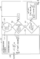
- Fig. 3 shows the structure of a first superordinate first partial control relating to the system 1000 with control and processor means.
- the interface 510 described above initially provides the number of available internal combustion engine generator units 400, which is also referred to below as #GENSETS, as an essential indication of power generation.
- #GENSETS are those in Fig. 1 designated gensets with the internal combustion engines of units 410 and 430; in the present case this is a number of six gensets.
- load consumers are also available at the interface 510. They come from Fig. 1 designated load consumers - in particular the propellers 201, 202, 203, 204, 205 as well as the other load consumers 207 to 209 - are used. The load requirements are described as part of a load requirement scope for each load consumer.
- this is an active load P i , a load jump ⁇ P i l and a load ramp ⁇ P i l .
- the first partial control 501 intervening in the interface 510 uses this to determine a load requirement scope, which in the present case is determined with comparatively little effort by the sum of the active loads P i l, a maximum of load jumps ⁇ P i l and a superordinate value of the load ramps ⁇ P i resbl .
- the latter can also take place, for example, as a maximum value formation or as an upper limit value or upper mean value of all load ramps.
- the operating states Z * and the state variables 508 describing them or the possible operating state range ZB * are then initially made available in a step 511 on the basis of the computational model 504.
- This information basically enables the specification of the services available in a transient operating state as well as all load switching capacities of the number of available internal combustion engines on the basis of the computing model 504.
- a step 512 a comparison is made as to whether the sum of all load switching capacities and available outputs of the internal combustion engines is greater than the load requirement scope of the number of load consumers as it is made available via the interface 510 of the first partial control.
- step Y1 it is then checked whether the state variables available via available gensets are optimized. This is not the case if the summary boundary condition mentioned in the second N 2 branch of the first sub-regulation is not met. Specifically, it is checked whether the sum of all individual possible power jumps ⁇ P j is greater than a maximum of the load jumps for the system 1000.
- the aforementioned steps 511 determining the operating state Z * and operating state range ZB *), 512 (determining the number of units 400 to be connected), 513 (optimizing with regard to the overall boundary condition) are continuous, ie "in the loop".
- Both a maximum change in load MAX ( ⁇ P l ) and the load-bearing capacity ZB * depend on the current operating state Z *.
- the continuous mode of operation ensures that the system 1000 of the internal combustion engine generator system is in a safe and, at the same time, optimal operating state at the higher-level control level.
- the one defined in the N 2 branch, in Fig. 3 The summary boundary condition shown has an amount of a variable load distribution var P j related to the requested unit 400 in relation to the current operating state Z * and variable speed distribution n j .
- These variable load distributions for a single internal combustion engine 400 which are referred to as the requested load jump ⁇ P j req and requested load ramp ⁇ P j req , are dependent on the load requirement and the load distribution in FIG Fig. 4 second sub-regulation 502 described in more detail is provided.
- the second partial control 502 which relates to the variable-speed internal combustion engine, also has the results of the computational model 504 available, namely the operating state Z * and the operating state range ZB *.
- a permissible range of a load switching capacity L adm contained therein can be specified from the operating state range ZB *.
- this is defined by a permissible power jump ⁇ P j adm and a permissible power ramp ⁇ P j adm in relation to the current operating state Z *; this definition also applies in a transient operation of the internal combustion engine 400, which in step 522 for the second partial control in FIG Fig. 4 is shown.
- step 523 of the second sub-regulation 502 the aforementioned parameters of the permissible load switching capacity ⁇ P adm , ⁇ P adm are compared with the variable parameters of the load distribution ⁇ P req ⁇ P req which are dependent on the load requirement and are dependent on the load requirement.
- a speed n new of the internal combustion engine is adapted in a first N 1 branch of the second sub-control 502 while repeating the aforementioned steps 521, 522, 523 until the in Step 523 listed condition is met. If this is the case, it can be assumed that the operating state Z * of the internal combustion engine is safely selected, at least with regard to the load requirement and the available load switching capacity of the internal combustion engine.
- the second sub-control 502 checks whether all the optimizable state variables of the internal combustion engine satisfy a further boundary condition.
- an optimization strategy can consist in using the lowest possible fuel consumption for the internal combustion engine.
- one optimization variable is to operate the internal combustion engine in a range with the lowest possible specific consumption (sfc as low as possible). If the previously selected speed n new does not yet meet the optimized requirements, the speed n is optimized in a second N 2 branch of the second partial control until it corresponds to an optimal speed n opt , whereby the condition mentioned in step 523 is nevertheless met got to. I.e. even with an optimized speed, the internal combustion engine subject to the second partial control 502 should have a load switching capacity that is greater than the load requirement-dependent variable load distribution for the internal combustion engine.
- the second partial control is operated continuously "in the loop" in a second Y 2 branch by repeating the aforementioned steps 521 to 524.
- the repetition rate of steps 521 to 524 can be selected according to the dynamics of the transient state of the internal combustion engine, so that it is ensured that the aforementioned safe and optimal operating conditions of the internal combustion engine are met both in the case of fast and slow dynamic transient state changes.
- the operating state Z * and the operating state range ZB * from step 521 for the internal combustion engine are transmitted to step 511 of the first sub-regulation 501, so that the higher-level first sub-regulation 501 can, if necessary, redefine power requirements and these can be fed back in step 523 of the second partial control 502 can feed.
- either another unit is started as part of the N 1 branch of the first partial control 501.Otherwise, if, for example, all units have already been started - the units in operation must be in operating points Z * be driven, so the possibly Required load change of step 523 of the second partial control 502 can be driven.
- the present embodiment also provides an error scenario in which, in the event of an error, the internal combustion engines 401 to 408 (except possibly 403), which are otherwise regarded as variable-speed diesel engines, are operated as constant-speed motors, as is the case with conventional gensets.
- the present method offers the advantage that - if at all - only a targeted load shedding of more or less critical consumers is required, since a constant simulation of a transient state of the diesel engine is also implemented within the framework of the computational model 504 and the method steps 511 and 521 becomes.
Landscapes
- Engineering & Computer Science (AREA)
- Mechanical Engineering (AREA)
- Chemical & Material Sciences (AREA)
- Combustion & Propulsion (AREA)
- General Engineering & Computer Science (AREA)
- Ocean & Marine Engineering (AREA)
- Power Engineering (AREA)
- Transportation (AREA)
- Supply And Distribution Of Alternating Current (AREA)
- Control Of Eletrric Generators (AREA)
- Control Of Vehicle Engines Or Engines For Specific Uses (AREA)
Claims (20)
- Procédé de commande et de régulation d'un système de groupe électrogène à moteur à combustion interne (1000) comprenant un certain nombre de groupes électrogènes à moteur à combustion interne (400) pouvant être raccordés à un réseau de distribution et générant de l'énergie électrique, et des consommateurs de charge (200) consommant de l'énergie électrique, un groupe (400) comprenant un moteur à combustion interne (401, 402, 404 - 408) à variation de la vitesse de rotation et un générateur (421 - 428), comprenant les étapes consistant à:(a) déterminer un état de fonctionnement actuel (Z*) du moteur à combustion interne (401, 402, 404-408) du au moins un groupe électrogène à moteur à combustion interne (400) ; et(b) dériver une plage d'états de fonctionnement (ZB*) décrivant une capacité d'augmentation de charge (Ladm) en fonction de l'état de fonctionnement actuel (Z*) pour le moteur à combustion interne de l'au moins un groupe électrogène à moteur à combustion interne (400), où
la détermination de l'état de fonctionnement actuel (Z*) et la dérivation de la plage d'états de fonctionnement (ZB*) a lieu sur la base d'un modèle de calcul (504) pour le moteur à combustion interne (401, 402, 405-408);(c) fournir des demandes de charge possibles du nombre de consommateurs de charge (200) décrivant l'ampleur des demandes de charge ; et caractérisé en ce que(d) en tenant compte de l'état de fonctionnement actuel (Z*) et de la capacité d'augmentation de charge (Ladm) du moteur à combustion interne (401, 402, 404 - 408) du au moins un groupe électrogène à moteur à combustion interne (400) :- la détermination d'un nombre (#GENSET) de groupes électrogènes à moteur à combustion interne (400)) à connecter au réseau de distribution en fonction de l'ampleur de demande de charge ; et- la détermination de la distribution de charge variable (Lreq) et/ou une distribution de vitesse variable (nreq) pour le nombre de moteurs à combustion interne (400) en fonction de l'ampleur de demande de charge. - Procédé selon la revendication 1, caractérisé en ce que lors du calcul de la plage d'état de fonctionnement (ZB*) une plage de fonctionnement admissible d'un générateur du groupe électrogène à moteur à combustion interne (400), notamment en ce qui concerne la vitesse, l'excitation et/ou la tension, est prise en compte.
- Procédé selon la revendication 1 ou 2, caractérisé en ce que
les étapes (c) et/ou (d) sont exécutés dans une première régulation partielle de niveau supérieur (501), et les étapes (a) et (b) dans une deuxième régulation partielle (502). - Procédé selon la revendication 3, caractérisé en ce que la première régulation partielle de niveau supérieur (501) concerne le système et/ou la seconde régulation partielle (502) concerne le moteur à combustion interne à vitesse variable (401, 402, 404-408).
- Procédé selon l'une quelconque des revendications 1 à 4, caractérisé en ce qu'une capacité d'augmentation de charge (Ladm) à un état de fonctionnement courant (Z*) est caractérisée par un saut de puissance possible ou admissible (ΔPj)adm et une rampe de puissance possible ou admissible (δPj)adm et/ou une demande de charge possible du au moins un consommateur de charge (200) est déterminée par une charge active (Pj), un saut de charge (ΔPj) et/ou une rampe de charge (δPj).
- Procédé selon l'une quelconque des revendications 1 à 5, comprenant en outre l'étape :
e) de comparaison de la capacité d'augmentation de charge (Ladm) avec la répartition de charge variable (Lreq) en fonction de l'ampleur de demande de charge pour le moteur à combustion interne (400), en particulier lors d'une deuxième régulation partielle appropriée (502) du moteur à combustion interne à vitesse variable (400). - Procédé selon l'une quelconque des revendications 1 à 6, caractérisé en ce que la répartition de charge variable (Lreq) et/ou la répartition de vitesse (nreq) est soumise à une condition marginale de sommation, dans lequel la somme de toutes les capacités d'augmentation de charge (Ladm) des moteurs à combustion interne basée sur le modèle (504) de calcul pour le au moins un moteur à combustion interne (400) est supérieur à l'ampleur des demandes de charge du nombre de consommateurs de charge (200).
- Procédé selon l'une quelconque des revendications 5 à 7, caractérisé en ce qu'une ampleur des demandes de charge du nombre de consommateurs de charge est déterminée par la somme des charges actives (Pj), un maximum des sauts de charge (ΔPi MAX) et/ou une valeur de niveau supérieur des rampes de charge (δPi RESBL)
- Procédé selon l'une quelconque des revendications 5 à 8, caractérisé en ce que la condition marginale sommaire est formée en ce que la somme de tous les sauts de puissance représentables (SUM(ΔPj)) est supérieure à un maximum des sauts de charge (MAX ΔPj) du nombre de consommateurs de charge et/ou la somme de toutes les rampes de puissance représentables individuelles (SUM(δPj)) est supérieure à une valeur de niveau supérieur des rampes de charge (RESBL δPj).
- Procédé selon l'une quelconque des revendications 1 à 9, caractérisé en ce que dans le moteur à combustion interne à vitesse variable, la vitesse (nj) et la puissance (Pj) sont conditionnellement réglables indépendamment, notamment dans une deuxième régulation partielle (502) la vitesse du moteur à combustion interne à vitesse variable (400) est adaptée.
- Procédé selon l'une quelconque des revendications 1 à 10, caractérisé en ce que le modèle arithmétique (504) est un modèle thermodynamique de l'état de fonctionnement (Z*) du moteur à combustion interne (400), avec un certain nombre de variables choisies dans le groupe constitué par :la puissance (Pj) du moteur à combustion interne,la vitesse (nj) du moteur à combustion interne,la température (Tj) du moteur à combustion interne,la température ambiante (Tamb),la pression ambiante (Pamb),la contre-pression d'échappement (PAG),le moment d'inertie (Jj) du groupe électrogène à moteur à combustion interne (401, 402, 404-408),la consommation spécifique de carburant (sfc).
- Procédé selon l'une quelconque des revendications 1 à 11, caractérisé en ce que l'on détermine un nombre (#GENSET) de groupes électrogènes à moteur à combustion interne à connecter au réseau de distribution en fonction de l'étendue de besoin de charge en comparant la somme de charge des consommateurs (SUM(LOAD)) avec la puissance totale des groupes électrogènes à moteur à combustion interne (SUM(GENSET)).
- Procédé selon l'une quelconque des revendications 1 à 12, caractérisé en ce qu'une vitesse (nj) du moteur à combustion interne et/ou une autre variable caractérisant l'état de fonctionnement est modifiée :- lorsqu'une quantité de distribution de charge variable liée au groupe demandé par rapport à l'état de fonctionnement actuel se situe en dehors d'une plage d'état de fonctionnement admissible (ZB*) du moteur à combustion interne qui décrit la capacité d'augmentation de charge, et/ou- si une grandeur non encore optimisée du modèle de calcul est disponible.
- Procédé selon l'une quelconque des revendications 1 à 13, caractérisées en ce que, en particulier pour la première et/ou la seconde régulation partielle (501, 502), une stratégie d'optimisation est spécifiée, au sein des conditions limites de laquelle un nouvel état de fonctionnement du moteur à combustion interne est établi dans une plage d'état de fonctionnement sûr (ZB *).
- Procédé selon l'une quelconque des revendications 1 à 14, caractérisé en ce qu'une plage d'état de fonctionnement (ZB*) est dérivée à plusieurs reprises pour des changements d'état de fonctionnement, en particulier comprenant une première régulation partielle (501) et/ou une deuxième régulation partielle (502) d'une boucle de régulation (514, 525), dans laquelle une plage d'état de fonctionnement (ZB*) est dérivée à plusieurs reprises pour les changements d'état de fonctionnement.
- Dispositif de commande et de régulation d'un système de moteur-générateur à combustion interne avec un certain nombre de groupes électrogènes à moteur à combustion interne qui peuvent être connectées à un réseau de distribution, générant de l'énergie électrique et consommant de l'énergie électrique, dans lequel un groupe présente un moteur à combustion interne à vitesse variable et un générateur, comprenant des moyens de commande et processeur pour(a) déterminer un état de fonctionnement actuel (Z*) du moteur à combustion interne de l'au moins un groupe électrogène à moteur à combustion interne ;(b) dériver une plage d'état de fonctionnement (ZB*), qui décrit une capacité d'augmentation de charge en fonction de l'état de fonctionnement actuel (Z*) pour le moteur à combustion interne de l'au moins un groupe électrogène à moteur à combustion interne, dans lequel
la détermination de l'état de fonctionnement actuel (Z*) et la dérivation de la plage d'état de fonctionnement a lieu sur la base d'un modèle de calcul pour le moteur à combustion interne ;(c) fournir une ampleur des demandes de charge décrivant les demandes de charge possibles du nombre de consommateurs de charge ; caractérisé par des moyens de commande et de traitement pour(d) déterminer un nombre de groupes électrogènes à moteur à combustion interne à connecter au réseau de distribution en fonction de la demande de charge,- déterminer une répartition de charge variable et/ou une distribution de vitesse variable sur le nombre de moteurs à combustion interne du nombre de groupes électrogènes à moteur à combustion interne en fonction de l'ampleur de demande de charge,- en tenant compte de l'état de fonctionnement actuel et de la capacité d'augmentation de charge du moteur à combustion interne de l'au moins un groupe électrogène à moteur à combustion interne. - Dispositif de commande et de régulation selon la revendication 16, caractérisé en ce qu'une deuxième régulation partielle, en particulier du moteur à combustion interne à vitesse variable, est pourvue de moyens de commande et de traitement pour réaliser les étapes (a) et (b) et/ou une première, notamment la première régulation partielle de niveau supérieur liée au système est pourvue de moyens de commande et de processeur pour exécuter l'étape (c), en particulier l'étape (d).
- Système de moteur-générateur à combustion interne avec un certain nombre de groupes électrogènes à moteur à combustion interne qui peuvent être connectées à un réseau de distribution, générant de l'énergie électrique et des consommateurs de charge consommant de l'énergie électrique, un groupe ayant un moteur à combustion interne à vitesse variable et un générateur et avec un dispositif de commande et de régulation selon la revendication 16 ou 17.
- Véhicule terrestre ou nautique - en particulier véhicule polyvalent, véhicule utilitaire ou navire - avec un système de moteur-générateur à combustion interne selon la revendication 18.
- Système stationnaire de génération d'énergie électrique avec un système de moteur-générateur à combustion interne selon la revendication 18.
Applications Claiming Priority (2)
| Application Number | Priority Date | Filing Date | Title |
|---|---|---|---|
| DE102011076073A DE102011076073B4 (de) | 2011-05-18 | 2011-05-18 | Verfahren zur Steuerung und Regelung eines Brennkraftmaschinen-Generator-Systems, Einrichtung zur Steuerung und Regelung sowie Brennkraftmaschinen-Generator-System und Land- oder Wasserfahrzeug oder stationäre Anlage zur Erzeugung elektrischer Energie |
| PCT/EP2012/002082 WO2012156078A2 (fr) | 2011-05-18 | 2012-05-15 | Procédé de commande et de régulation d'un système moteur à combustion interne/générateur, dispositif de commande et de régulation ainsi que système moteur à combustion interne/générateur et véhicule routier ou naval ou installation fixe pour produire de l'énergie électrique |
Publications (2)
| Publication Number | Publication Date |
|---|---|
| EP2710246A2 EP2710246A2 (fr) | 2014-03-26 |
| EP2710246B1 true EP2710246B1 (fr) | 2021-01-06 |
Family
ID=46178516
Family Applications (1)
| Application Number | Title | Priority Date | Filing Date |
|---|---|---|---|
| EP12724291.5A Active EP2710246B1 (fr) | 2011-05-18 | 2012-05-15 | Procédé et dispositif de commande et de régulation d'un système moteur à combustion interne/générateur |
Country Status (5)
| Country | Link |
|---|---|
| US (1) | US9441537B2 (fr) |
| EP (1) | EP2710246B1 (fr) |
| CN (1) | CN103688041B (fr) |
| DE (1) | DE102011076073B4 (fr) |
| WO (1) | WO2012156078A2 (fr) |
Families Citing this family (21)
| Publication number | Priority date | Publication date | Assignee | Title |
|---|---|---|---|---|
| CN104870787B (zh) * | 2012-12-20 | 2017-06-06 | 瓦锡兰芬兰有限公司 | 内燃机的控制系统 |
| EP3011654A1 (fr) * | 2013-06-17 | 2016-04-27 | Deif A/S | Système d'alimentation |
| US9709964B2 (en) * | 2014-07-11 | 2017-07-18 | Cummins Power Generation Ip, Inc. | Genset power control in power systems |
| DE102014215536A1 (de) * | 2014-08-06 | 2016-02-11 | Volkswagen Aktiengesellschaft | Bordnetzanordnung und Verfahren zum Betreiben eines Bordnetzes eines elektrisch antreibbaren Fortbewegungsmittels mit einer Brennstoffzelle |
| CN106605347A (zh) * | 2014-09-16 | 2017-04-26 | 瓦锡兰芬兰有限公司 | 在速度控制模式或负载控制模式下驱动动力引擎单元并更改控制模式的控制方法和系统 |
| DE102014017500B4 (de) * | 2014-11-27 | 2026-02-12 | Everllence Se | Verfahren und Steuerungseinrichtung zum Betreiben eines Systems aus mehreren Brennkraftmaschinen |
| DE102015201477B4 (de) | 2015-01-28 | 2021-06-24 | Mtu Friedrichshafen Gmbh | Aggregat zur Stromerzeugung, Stromnetz mit einem solchen Aggregat, Kraftfahrzeug mit einem solchen Stromnetz oder Aggregat, und Verfahren zum Betreiben eines solchen Aggregats zur Stromerzeugung |
| EP3086432B1 (fr) | 2015-04-23 | 2018-07-18 | GE Energy Power Conversion Technology Ltd | Systèmes de distribution de puissance |
| DE102015007941B3 (de) * | 2015-06-19 | 2016-11-17 | Peter Andersen | Energieversorgungs- und Antriebsanlage für Schiffe und Offshore-Einheiten |
| WO2017097334A1 (fr) * | 2015-12-07 | 2017-06-15 | Abb Schweiz Ag | Commande de paramètre de moteur |
| US20170198648A1 (en) * | 2016-01-08 | 2017-07-13 | David E. James | System and method for controlling an operating mode of a motor-generator |
| RU2640378C2 (ru) * | 2016-03-09 | 2017-12-28 | Федеральное государственное унитарное предприятие "Крыловский государственный научный центр" | Электрическая передача мощности тягового транспортного средства на переменном токе |
| JP6569141B2 (ja) * | 2016-12-07 | 2019-09-04 | 三菱造船株式会社 | 船舶の航行方法、及び船舶 |
| US10587115B2 (en) * | 2016-12-20 | 2020-03-10 | Google Inc. | Modular direct current (DC) architectures |
| US20180334177A1 (en) * | 2017-05-19 | 2018-11-22 | Optifuel Systems, LLC | Hybrid power system for locomotive |
| DE102018100541B3 (de) * | 2018-01-11 | 2019-07-11 | Mtu Friedrichshafen Gmbh | Verfahren zur Steuerung und Regelung einer Brennkraftmaschine mit Generator und Asynchronmaschine, Steuer- und Regeleinrichtung für eine Brennkraftmaschine mit Generator und Asynchronmaschine sowie Brennkraftmaschine mit Generator und Asynchronmaschine |
| EP3521587A1 (fr) * | 2018-02-06 | 2019-08-07 | Innio Jenbacher GmbH & Co OG | Commande de pression redondante |
| US11264801B2 (en) * | 2018-02-23 | 2022-03-01 | Schlumberger Technology Corporation | Load management algorithm for optimizing engine efficiency |
| CN110707971B (zh) * | 2019-09-03 | 2024-09-10 | 无锡法尔胜悦能动力有限公司 | 一种增强燃气发电机组突变负载能力的系统及控制方法 |
| CN112879171A (zh) * | 2021-04-14 | 2021-06-01 | 广东西电动力科技股份有限公司 | 一种沼气机组多机并车系统 |
| US11598282B1 (en) | 2022-02-23 | 2023-03-07 | Atlantic Towing Limited | Systems and methods for optimizing vessel fuel consumption |
Family Cites Families (14)
| Publication number | Priority date | Publication date | Assignee | Title |
|---|---|---|---|---|
| JPH09195811A (ja) * | 1996-01-19 | 1997-07-29 | Komatsu Ltd | 発電機の自動負荷分担装置及びその制御方法 |
| DE19937139C1 (de) | 1999-08-06 | 2001-04-05 | Mtu Friedrichshafen Gmbh | Verfahren und Einrichtung zur Steuerung einer Brennkraftmaschine |
| DE10302263B3 (de) | 2003-01-22 | 2004-03-18 | Mtu Friedrichshafen Gmbh | Verfahren zur Drehzahl-Regelung einer Brennkraftmaschine |
| DE102004015973B3 (de) | 2004-04-01 | 2005-10-06 | Mtu Friedrichshafen Gmbh | Verfahren zur Steuerung und Regelung einer Brennkraftmaschinen-Generator-Einheit |
| JP2006132392A (ja) | 2004-11-04 | 2006-05-25 | Mitsubishi Fuso Truck & Bus Corp | 内燃機関の排気浄化装置 |
| CN100567719C (zh) * | 2004-11-04 | 2009-12-09 | 丰田自动车株式会社 | 动力输出装置和用于该装置的控制方法 |
| JP4535036B2 (ja) | 2006-07-12 | 2010-09-01 | トヨタ自動車株式会社 | 内燃機関の電源システム |
| GB2443002A (en) * | 2006-10-16 | 2008-04-23 | Converteam Ltd | dc power distribution system |
| DE102007040905A1 (de) * | 2007-08-30 | 2009-03-05 | Bayerische Motoren Werke Aktiengesellschaft | Verfahren und Bordnetz eines Kraftfahrzeugs mit vorausschauendem temporären Momentenvorhalt des Verbrennungsmotors |
| US8000866B2 (en) * | 2007-11-04 | 2011-08-16 | GM Global Technology Operations LLC | Engine control system for torque management in a hybrid powertrain system |
| US8258640B2 (en) * | 2008-10-30 | 2012-09-04 | Caterpillar Inc. | Power system having transient control |
| AT508573B1 (de) | 2009-07-29 | 2011-06-15 | Klein Herbert Mag | Hochsee- oder binnenschiff |
| DE102009036277A1 (de) | 2009-08-05 | 2011-02-17 | Man Diesel & Turbo Se | Mehrmotorenanlage und Verfahren zum Betreiben dieser |
| JP5107987B2 (ja) * | 2009-08-21 | 2012-12-26 | 新潟原動機株式会社 | 舶用推進装置 |
-
2011
- 2011-05-18 DE DE102011076073A patent/DE102011076073B4/de not_active Expired - Fee Related
-
2012
- 2012-05-15 WO PCT/EP2012/002082 patent/WO2012156078A2/fr not_active Ceased
- 2012-05-15 EP EP12724291.5A patent/EP2710246B1/fr active Active
- 2012-05-15 CN CN201280023977.4A patent/CN103688041B/zh active Active
- 2012-05-15 US US14/118,437 patent/US9441537B2/en active Active
Non-Patent Citations (1)
| Title |
|---|
| None * |
Also Published As
| Publication number | Publication date |
|---|---|
| CN103688041B (zh) | 2017-04-12 |
| CN103688041A (zh) | 2014-03-26 |
| WO2012156078A2 (fr) | 2012-11-22 |
| US20140290591A1 (en) | 2014-10-02 |
| DE102011076073A1 (de) | 2012-11-22 |
| EP2710246A2 (fr) | 2014-03-26 |
| DE102011076073B4 (de) | 2013-01-03 |
| US9441537B2 (en) | 2016-09-13 |
| WO2012156078A3 (fr) | 2013-03-28 |
Similar Documents
| Publication | Publication Date | Title |
|---|---|---|
| EP2710246B1 (fr) | Procédé et dispositif de commande et de régulation d'un système moteur à combustion interne/générateur | |
| EP2013077B1 (fr) | Procédé de fonctionnement d'un système de commande de navire avec récupération de chaleur et système de commande de navire avec récupération de chaleur | |
| DE102012208336B4 (de) | Verfahren und vorrichtung zum betreiben einesantriebsstrangsystems, welches eine elektrische maschinemit einer nicht verbundenen hochspannungsbatterie enthält | |
| DE102007029352B4 (de) | Elektrische Fahrzeuggeneneratorvorrichtung | |
| DE10223117B4 (de) | Verfahren und Anordnung zur Steuerung der Energieversorgung eines elektrischen Antriebs mit einem hybriden Energieversorgungssystem in einem Fahrzeug | |
| EP2164753B1 (fr) | Procédé et dispositif pour faire fonctionner un système moteur hybride pour un navire | |
| EP2758268B1 (fr) | Dispositif de commande d'un convertisseur continu-continu d'un système de propulsion électrique et procédé permettant de faire fonctionner un convertisseur continu-continu | |
| DE112008002805B4 (de) | Steuervorrichtung für eine drehende elektrische Maschine | |
| DE102018201584B4 (de) | Hybridfahrzeug | |
| DE102011110906A1 (de) | Verfahren und Vorrichtung zum Steuern einer Hochspannungsbatterieverbindung für ein Hybridantriebsstrangsystem | |
| DE10036099A1 (de) | Verfahren zur Regelung einer elektrischen Maschine mit Pulswechselrichter | |
| EP1894835B1 (fr) | Procédé de fonctionnement d'un navire doté d'un entraînement électrique et entraînement auxiliaire de moteurs à combustion interne ainsi que réalisation du procédé adapté au navire | |
| DE102010050418B4 (de) | Fahrzeugladevorrichtung | |
| EP1894836B1 (fr) | Navire doté d'un entraînement électrique et entraînement auxiliaire de moteurs à combustion interne | |
| DE102021102666A1 (de) | Regelkreissteuerung für den transienten betrieb von elektrischen maschinen mit variablem fluss und permanentmagneten | |
| DE102017205161A1 (de) | System zur steuerung der lastverteilung | |
| DE102009017502B4 (de) | Fahrzeug-montierte Stromversorgung | |
| DE102013205969B4 (de) | Fahrzeug mit einer elektrischen Maschine mit zwei Spannungslagen und Verfahren zum Betreiben dieser | |
| EP1410479B1 (fr) | Procede et dispositif de commande de la recharge d'une batterie de vehicule automobile | |
| DE102014212743A1 (de) | Aufwärtsumsetzer-totzeitkompensation | |
| DE102006022706B3 (de) | Antriebsvorrichtung und Regelungsverfahren für ein elektrisch angetriebenes Fahrzeug | |
| DE102004057100A1 (de) | Antriebsvorrichtung und Regelungsverfahren für ein elektrisch angetriebenes Fahrzeug | |
| DE10011601A1 (de) | Antriebseinrichtung für Schiffspropeller | |
| DE102011088786B4 (de) | Verfahren zum Betreiben einer Energieversorgungseinheit für ein Bordnetz eines Kraftfahrzeugs und Feldregler | |
| DE102006008365A1 (de) | Verfahren zur Regelung der Leistungsabgabe an die Räder eines Kraftfahrzeuges |
Legal Events
| Date | Code | Title | Description |
|---|---|---|---|
| PUAI | Public reference made under article 153(3) epc to a published international application that has entered the european phase |
Free format text: ORIGINAL CODE: 0009012 |
|
| 17P | Request for examination filed |
Effective date: 20131024 |
|
| AK | Designated contracting states |
Kind code of ref document: A2 Designated state(s): AL AT BE BG CH CY CZ DE DK EE ES FI FR GB GR HR HU IE IS IT LI LT LU LV MC MK MT NL NO PL PT RO RS SE SI SK SM TR |
|
| DAX | Request for extension of the european patent (deleted) | ||
| 17Q | First examination report despatched |
Effective date: 20150210 |
|
| RIC1 | Information provided on ipc code assigned before grant |
Ipc: F02D 41/14 20060101ALI20200221BHEP Ipc: F02D 25/00 20060101ALI20200221BHEP Ipc: B63H 21/21 20060101ALI20200221BHEP Ipc: B60L 50/13 20190101ALI20200221BHEP Ipc: F02D 41/02 20060101AFI20200221BHEP Ipc: B63J 3/00 20060101ALI20200221BHEP Ipc: F02D 29/06 20060101ALI20200221BHEP Ipc: F02B 77/13 20060101ALI20200221BHEP Ipc: H02J 1/14 20060101ALI20200221BHEP Ipc: H02J 4/00 20060101ALI20200221BHEP Ipc: F02B 75/16 20060101ALI20200221BHEP Ipc: H02P 9/04 20060101ALI20200221BHEP Ipc: F02B 63/04 20060101ALI20200221BHEP |
|
| GRAP | Despatch of communication of intention to grant a patent |
Free format text: ORIGINAL CODE: EPIDOSNIGR1 |
|
| STAA | Information on the status of an ep patent application or granted ep patent |
Free format text: STATUS: GRANT OF PATENT IS INTENDED |
|
| INTG | Intention to grant announced |
Effective date: 20200420 |
|
| GRAS | Grant fee paid |
Free format text: ORIGINAL CODE: EPIDOSNIGR3 |
|
| GRAA | (expected) grant |
Free format text: ORIGINAL CODE: 0009210 |
|
| STAA | Information on the status of an ep patent application or granted ep patent |
Free format text: STATUS: THE PATENT HAS BEEN GRANTED |
|
| AK | Designated contracting states |
Kind code of ref document: B1 Designated state(s): AL AT BE BG CH CY CZ DE DK EE ES FI FR GB GR HR HU IE IS IT LI LT LU LV MC MK MT NL NO PL PT RO RS SE SI SK SM TR |
|
| REG | Reference to a national code |
Ref country code: GB Ref legal event code: FG4D Free format text: NOT ENGLISH |
|
| REG | Reference to a national code |
Ref country code: AT Ref legal event code: REF Ref document number: 1352622 Country of ref document: AT Kind code of ref document: T Effective date: 20210115 Ref country code: CH Ref legal event code: EP |
|
| REG | Reference to a national code |
Ref country code: DE Ref legal event code: R096 Ref document number: 502012016573 Country of ref document: DE |
|
| REG | Reference to a national code |
Ref country code: IE Ref legal event code: FG4D Free format text: LANGUAGE OF EP DOCUMENT: GERMAN |
|
| REG | Reference to a national code |
Ref country code: NL Ref legal event code: MP Effective date: 20210106 |
|
| REG | Reference to a national code |
Ref country code: LT Ref legal event code: MG9D |
|
| PG25 | Lapsed in a contracting state [announced via postgrant information from national office to epo] |
Ref country code: LT Free format text: LAPSE BECAUSE OF FAILURE TO SUBMIT A TRANSLATION OF THE DESCRIPTION OR TO PAY THE FEE WITHIN THE PRESCRIBED TIME-LIMIT Effective date: 20210106 Ref country code: PT Free format text: LAPSE BECAUSE OF FAILURE TO SUBMIT A TRANSLATION OF THE DESCRIPTION OR TO PAY THE FEE WITHIN THE PRESCRIBED TIME-LIMIT Effective date: 20210506 Ref country code: FI Free format text: LAPSE BECAUSE OF FAILURE TO SUBMIT A TRANSLATION OF THE DESCRIPTION OR TO PAY THE FEE WITHIN THE PRESCRIBED TIME-LIMIT Effective date: 20210106 Ref country code: GR Free format text: LAPSE BECAUSE OF FAILURE TO SUBMIT A TRANSLATION OF THE DESCRIPTION OR TO PAY THE FEE WITHIN THE PRESCRIBED TIME-LIMIT Effective date: 20210407 Ref country code: HR Free format text: LAPSE BECAUSE OF FAILURE TO SUBMIT A TRANSLATION OF THE DESCRIPTION OR TO PAY THE FEE WITHIN THE PRESCRIBED TIME-LIMIT Effective date: 20210106 Ref country code: NL Free format text: LAPSE BECAUSE OF FAILURE TO SUBMIT A TRANSLATION OF THE DESCRIPTION OR TO PAY THE FEE WITHIN THE PRESCRIBED TIME-LIMIT Effective date: 20210106 Ref country code: NO Free format text: LAPSE BECAUSE OF FAILURE TO SUBMIT A TRANSLATION OF THE DESCRIPTION OR TO PAY THE FEE WITHIN THE PRESCRIBED TIME-LIMIT Effective date: 20210406 Ref country code: BG Free format text: LAPSE BECAUSE OF FAILURE TO SUBMIT A TRANSLATION OF THE DESCRIPTION OR TO PAY THE FEE WITHIN THE PRESCRIBED TIME-LIMIT Effective date: 20210406 |
|
| PG25 | Lapsed in a contracting state [announced via postgrant information from national office to epo] |
Ref country code: SE Free format text: LAPSE BECAUSE OF FAILURE TO SUBMIT A TRANSLATION OF THE DESCRIPTION OR TO PAY THE FEE WITHIN THE PRESCRIBED TIME-LIMIT Effective date: 20210106 Ref country code: PL Free format text: LAPSE BECAUSE OF FAILURE TO SUBMIT A TRANSLATION OF THE DESCRIPTION OR TO PAY THE FEE WITHIN THE PRESCRIBED TIME-LIMIT Effective date: 20210106 Ref country code: RS Free format text: LAPSE BECAUSE OF FAILURE TO SUBMIT A TRANSLATION OF THE DESCRIPTION OR TO PAY THE FEE WITHIN THE PRESCRIBED TIME-LIMIT Effective date: 20210106 Ref country code: LV Free format text: LAPSE BECAUSE OF FAILURE TO SUBMIT A TRANSLATION OF THE DESCRIPTION OR TO PAY THE FEE WITHIN THE PRESCRIBED TIME-LIMIT Effective date: 20210106 |
|
| PG25 | Lapsed in a contracting state [announced via postgrant information from national office to epo] |
Ref country code: IS Free format text: LAPSE BECAUSE OF FAILURE TO SUBMIT A TRANSLATION OF THE DESCRIPTION OR TO PAY THE FEE WITHIN THE PRESCRIBED TIME-LIMIT Effective date: 20210506 |
|
| REG | Reference to a national code |
Ref country code: DE Ref legal event code: R097 Ref document number: 502012016573 Country of ref document: DE |
|
| PG25 | Lapsed in a contracting state [announced via postgrant information from national office to epo] |
Ref country code: EE Free format text: LAPSE BECAUSE OF FAILURE TO SUBMIT A TRANSLATION OF THE DESCRIPTION OR TO PAY THE FEE WITHIN THE PRESCRIBED TIME-LIMIT Effective date: 20210106 Ref country code: CZ Free format text: LAPSE BECAUSE OF FAILURE TO SUBMIT A TRANSLATION OF THE DESCRIPTION OR TO PAY THE FEE WITHIN THE PRESCRIBED TIME-LIMIT Effective date: 20210106 Ref country code: SM Free format text: LAPSE BECAUSE OF FAILURE TO SUBMIT A TRANSLATION OF THE DESCRIPTION OR TO PAY THE FEE WITHIN THE PRESCRIBED TIME-LIMIT Effective date: 20210106 |
|
| PLBE | No opposition filed within time limit |
Free format text: ORIGINAL CODE: 0009261 |
|
| STAA | Information on the status of an ep patent application or granted ep patent |
Free format text: STATUS: NO OPPOSITION FILED WITHIN TIME LIMIT |
|
| PG25 | Lapsed in a contracting state [announced via postgrant information from national office to epo] |
Ref country code: RO Free format text: LAPSE BECAUSE OF FAILURE TO SUBMIT A TRANSLATION OF THE DESCRIPTION OR TO PAY THE FEE WITHIN THE PRESCRIBED TIME-LIMIT Effective date: 20210106 Ref country code: SK Free format text: LAPSE BECAUSE OF FAILURE TO SUBMIT A TRANSLATION OF THE DESCRIPTION OR TO PAY THE FEE WITHIN THE PRESCRIBED TIME-LIMIT Effective date: 20210106 Ref country code: ES Free format text: LAPSE BECAUSE OF FAILURE TO SUBMIT A TRANSLATION OF THE DESCRIPTION OR TO PAY THE FEE WITHIN THE PRESCRIBED TIME-LIMIT Effective date: 20210106 Ref country code: DK Free format text: LAPSE BECAUSE OF FAILURE TO SUBMIT A TRANSLATION OF THE DESCRIPTION OR TO PAY THE FEE WITHIN THE PRESCRIBED TIME-LIMIT Effective date: 20210106 |
|
| 26N | No opposition filed |
Effective date: 20211007 |
|
| REG | Reference to a national code |
Ref country code: CH Ref legal event code: PL |
|
| PG25 | Lapsed in a contracting state [announced via postgrant information from national office to epo] |
Ref country code: MC Free format text: LAPSE BECAUSE OF FAILURE TO SUBMIT A TRANSLATION OF THE DESCRIPTION OR TO PAY THE FEE WITHIN THE PRESCRIBED TIME-LIMIT Effective date: 20210106 Ref country code: LI Free format text: LAPSE BECAUSE OF NON-PAYMENT OF DUE FEES Effective date: 20210531 Ref country code: LU Free format text: LAPSE BECAUSE OF NON-PAYMENT OF DUE FEES Effective date: 20210515 Ref country code: AL Free format text: LAPSE BECAUSE OF FAILURE TO SUBMIT A TRANSLATION OF THE DESCRIPTION OR TO PAY THE FEE WITHIN THE PRESCRIBED TIME-LIMIT Effective date: 20210106 Ref country code: CH Free format text: LAPSE BECAUSE OF NON-PAYMENT OF DUE FEES Effective date: 20210531 |
|
| REG | Reference to a national code |
Ref country code: BE Ref legal event code: MM Effective date: 20210531 |
|
| PG25 | Lapsed in a contracting state [announced via postgrant information from national office to epo] |
Ref country code: SI Free format text: LAPSE BECAUSE OF FAILURE TO SUBMIT A TRANSLATION OF THE DESCRIPTION OR TO PAY THE FEE WITHIN THE PRESCRIBED TIME-LIMIT Effective date: 20210106 |
|
| PG25 | Lapsed in a contracting state [announced via postgrant information from national office to epo] |
Ref country code: IE Free format text: LAPSE BECAUSE OF NON-PAYMENT OF DUE FEES Effective date: 20210515 |
|
| REG | Reference to a national code |
Ref country code: DE Ref legal event code: R081 Ref document number: 502012016573 Country of ref document: DE Owner name: ROLLS-ROYCE SOLUTIONS GMBH, DE Free format text: FORMER OWNER: MTU FRIEDRICHSHAFEN GMBH, 88045 FRIEDRICHSHAFEN, DE |
|
| PG25 | Lapsed in a contracting state [announced via postgrant information from national office to epo] |
Ref country code: IS Free format text: LAPSE BECAUSE OF FAILURE TO SUBMIT A TRANSLATION OF THE DESCRIPTION OR TO PAY THE FEE WITHIN THE PRESCRIBED TIME-LIMIT Effective date: 20210506 |
|
| REG | Reference to a national code |
Ref country code: AT Ref legal event code: MM01 Ref document number: 1352622 Country of ref document: AT Kind code of ref document: T Effective date: 20210515 |
|
| PG25 | Lapsed in a contracting state [announced via postgrant information from national office to epo] |
Ref country code: BE Free format text: LAPSE BECAUSE OF NON-PAYMENT OF DUE FEES Effective date: 20210531 |
|
| PG25 | Lapsed in a contracting state [announced via postgrant information from national office to epo] |
Ref country code: AT Free format text: LAPSE BECAUSE OF NON-PAYMENT OF DUE FEES Effective date: 20210515 |
|
| PG25 | Lapsed in a contracting state [announced via postgrant information from national office to epo] |
Ref country code: HU Free format text: LAPSE BECAUSE OF FAILURE TO SUBMIT A TRANSLATION OF THE DESCRIPTION OR TO PAY THE FEE WITHIN THE PRESCRIBED TIME-LIMIT; INVALID AB INITIO Effective date: 20120515 Ref country code: CY Free format text: LAPSE BECAUSE OF FAILURE TO SUBMIT A TRANSLATION OF THE DESCRIPTION OR TO PAY THE FEE WITHIN THE PRESCRIBED TIME-LIMIT Effective date: 20210106 |
|
| P01 | Opt-out of the competence of the unified patent court (upc) registered |
Effective date: 20230530 |
|
| PG25 | Lapsed in a contracting state [announced via postgrant information from national office to epo] |
Ref country code: MK Free format text: LAPSE BECAUSE OF FAILURE TO SUBMIT A TRANSLATION OF THE DESCRIPTION OR TO PAY THE FEE WITHIN THE PRESCRIBED TIME-LIMIT Effective date: 20210106 |
|
| PG25 | Lapsed in a contracting state [announced via postgrant information from national office to epo] |
Ref country code: TR Free format text: LAPSE BECAUSE OF FAILURE TO SUBMIT A TRANSLATION OF THE DESCRIPTION OR TO PAY THE FEE WITHIN THE PRESCRIBED TIME-LIMIT Effective date: 20210106 |
|
| PG25 | Lapsed in a contracting state [announced via postgrant information from national office to epo] |
Ref country code: MT Free format text: LAPSE BECAUSE OF FAILURE TO SUBMIT A TRANSLATION OF THE DESCRIPTION OR TO PAY THE FEE WITHIN THE PRESCRIBED TIME-LIMIT Effective date: 20210106 |
|
| PGFP | Annual fee paid to national office [announced via postgrant information from national office to epo] |
Ref country code: DE Payment date: 20250521 Year of fee payment: 14 |
|
| PGFP | Annual fee paid to national office [announced via postgrant information from national office to epo] |
Ref country code: GB Payment date: 20250521 Year of fee payment: 14 |
|
| PGFP | Annual fee paid to national office [announced via postgrant information from national office to epo] |
Ref country code: IT Payment date: 20250527 Year of fee payment: 14 |
|
| PGFP | Annual fee paid to national office [announced via postgrant information from national office to epo] |
Ref country code: FR Payment date: 20250528 Year of fee payment: 14 |
|
| REG | Reference to a national code |
Ref country code: DE Ref legal event code: R082 Ref document number: 502012016573 Country of ref document: DE Representative=s name: EISENFUEHR SPEISER PATENTANWAELTE RECHTSANWAEL, DE |