EP2710335B1 - Capteur optique - Google Patents
Capteur optique Download PDFInfo
- Publication number
- EP2710335B1 EP2710335B1 EP12722142.2A EP12722142A EP2710335B1 EP 2710335 B1 EP2710335 B1 EP 2710335B1 EP 12722142 A EP12722142 A EP 12722142A EP 2710335 B1 EP2710335 B1 EP 2710335B1
- Authority
- EP
- European Patent Office
- Prior art keywords
- measurement
- interferometer
- interferometers
- laser
- light
- Prior art date
- Legal status (The legal status is an assumption and is not a legal conclusion. Google has not performed a legal analysis and makes no representation as to the accuracy of the status listed.)
- Active
Links
Images


Classifications
-
- G—PHYSICS
- G01—MEASURING; TESTING
- G01D—MEASURING NOT SPECIALLY ADAPTED FOR A SPECIFIC VARIABLE; ARRANGEMENTS FOR MEASURING TWO OR MORE VARIABLES NOT COVERED IN A SINGLE OTHER SUBCLASS; TARIFF METERING APPARATUS; MEASURING OR TESTING NOT OTHERWISE PROVIDED FOR
- G01D5/00—Mechanical means for transferring the output of a sensing member; Means for converting the output of a sensing member to another variable where the form or nature of the sensing member does not constrain the means for converting; Transducers not specially adapted for a specific variable
- G01D5/26—Mechanical means for transferring the output of a sensing member; Means for converting the output of a sensing member to another variable where the form or nature of the sensing member does not constrain the means for converting; Transducers not specially adapted for a specific variable characterised by optical transfer means, i.e. using infrared, visible, or ultraviolet light
-
- G—PHYSICS
- G01—MEASURING; TESTING
- G01L—MEASURING FORCE, STRESS, TORQUE, WORK, MECHANICAL POWER, MECHANICAL EFFICIENCY, OR FLUID PRESSURE
- G01L11/00—Measuring steady or quasi-steady pressure of a fluid or a fluent solid material by means not provided for in group G01L7/00 or G01L9/00
- G01L11/02—Measuring steady or quasi-steady pressure of a fluid or a fluent solid material by means not provided for in group G01L7/00 or G01L9/00 by optical means
-
- G—PHYSICS
- G01—MEASURING; TESTING
- G01D—MEASURING NOT SPECIALLY ADAPTED FOR A SPECIFIC VARIABLE; ARRANGEMENTS FOR MEASURING TWO OR MORE VARIABLES NOT COVERED IN A SINGLE OTHER SUBCLASS; TARIFF METERING APPARATUS; MEASURING OR TESTING NOT OTHERWISE PROVIDED FOR
- G01D5/00—Mechanical means for transferring the output of a sensing member; Means for converting the output of a sensing member to another variable where the form or nature of the sensing member does not constrain the means for converting; Transducers not specially adapted for a specific variable
- G01D5/26—Mechanical means for transferring the output of a sensing member; Means for converting the output of a sensing member to another variable where the form or nature of the sensing member does not constrain the means for converting; Transducers not specially adapted for a specific variable characterised by optical transfer means, i.e. using infrared, visible, or ultraviolet light
- G01D5/266—Mechanical means for transferring the output of a sensing member; Means for converting the output of a sensing member to another variable where the form or nature of the sensing member does not constrain the means for converting; Transducers not specially adapted for a specific variable characterised by optical transfer means, i.e. using infrared, visible, or ultraviolet light by interferometric means
-
- G—PHYSICS
- G01—MEASURING; TESTING
- G01B—MEASURING LENGTH, THICKNESS OR SIMILAR LINEAR DIMENSIONS; MEASURING ANGLES; MEASURING AREAS; MEASURING IRREGULARITIES OF SURFACES OR CONTOURS
- G01B11/00—Measuring arrangements characterised by the use of optical techniques
-
- G—PHYSICS
- G01—MEASURING; TESTING
- G01B—MEASURING LENGTH, THICKNESS OR SIMILAR LINEAR DIMENSIONS; MEASURING ANGLES; MEASURING AREAS; MEASURING IRREGULARITIES OF SURFACES OR CONTOURS
- G01B9/00—Measuring instruments characterised by the use of optical techniques
- G01B9/02—Interferometers
- G01B9/02055—Reduction or prevention of errors; Testing; Calibration
- G01B9/0207—Error reduction by correction of the measurement signal based on independently determined error sources, e.g. using a reference interferometer
-
- G—PHYSICS
- G01—MEASURING; TESTING
- G01H—MEASUREMENT OF MECHANICAL VIBRATIONS OR ULTRASONIC, SONIC OR INFRASONIC WAVES
- G01H9/00—Measuring mechanical vibrations or ultrasonic, sonic or infrasonic waves by using radiation-sensitive means, e.g. optical means
-
- G—PHYSICS
- G02—OPTICS
- G02F—OPTICAL DEVICES OR ARRANGEMENTS FOR THE CONTROL OF LIGHT BY MODIFICATION OF THE OPTICAL PROPERTIES OF THE MEDIA OF THE ELEMENTS INVOLVED THEREIN; NON-LINEAR OPTICS; FREQUENCY-CHANGING OF LIGHT; OPTICAL LOGIC ELEMENTS; OPTICAL ANALOGUE/DIGITAL CONVERTERS
- G02F1/00—Devices or arrangements for the control of the intensity, colour, phase, polarisation or direction of light arriving from an independent light source, e.g. switching, gating or modulating; Non-linear optics
- G02F1/01—Devices or arrangements for the control of the intensity, colour, phase, polarisation or direction of light arriving from an independent light source, e.g. switching, gating or modulating; Non-linear optics for the control of the intensity, phase, polarisation or colour
- G02F1/21—Devices or arrangements for the control of the intensity, colour, phase, polarisation or direction of light arriving from an independent light source, e.g. switching, gating or modulating; Non-linear optics for the control of the intensity, phase, polarisation or colour by interference
-
- H—ELECTRICITY
- H04—ELECTRIC COMMUNICATION TECHNIQUE
- H04R—LOUDSPEAKERS, MICROPHONES, GRAMOPHONE PICK-UPS OR LIKE ACOUSTIC ELECTROMECHANICAL TRANSDUCERS; ELECTRIC HEARING AIDS; PUBLIC ADDRESS SYSTEMS
- H04R23/00—Transducers other than those covered by groups H04R9/00 - H04R21/00
- H04R23/008—Transducers other than those covered by groups H04R9/00 - H04R21/00 using optical signals for detecting or generating sound
-
- G—PHYSICS
- G01—MEASURING; TESTING
- G01B—MEASURING LENGTH, THICKNESS OR SIMILAR LINEAR DIMENSIONS; MEASURING ANGLES; MEASURING AREAS; MEASURING IRREGULARITIES OF SURFACES OR CONTOURS
- G01B9/00—Measuring instruments characterised by the use of optical techniques
- G01B9/02—Interferometers
-
- G—PHYSICS
- G02—OPTICS
- G02F—OPTICAL DEVICES OR ARRANGEMENTS FOR THE CONTROL OF LIGHT BY MODIFICATION OF THE OPTICAL PROPERTIES OF THE MEDIA OF THE ELEMENTS INVOLVED THEREIN; NON-LINEAR OPTICS; FREQUENCY-CHANGING OF LIGHT; OPTICAL LOGIC ELEMENTS; OPTICAL ANALOGUE/DIGITAL CONVERTERS
- G02F1/00—Devices or arrangements for the control of the intensity, colour, phase, polarisation or direction of light arriving from an independent light source, e.g. switching, gating or modulating; Non-linear optics
- G02F1/01—Devices or arrangements for the control of the intensity, colour, phase, polarisation or direction of light arriving from an independent light source, e.g. switching, gating or modulating; Non-linear optics for the control of the intensity, phase, polarisation or colour
- G02F1/21—Devices or arrangements for the control of the intensity, colour, phase, polarisation or direction of light arriving from an independent light source, e.g. switching, gating or modulating; Non-linear optics for the control of the intensity, phase, polarisation or colour by interference
- G02F1/216—Devices or arrangements for the control of the intensity, colour, phase, polarisation or direction of light arriving from an independent light source, e.g. switching, gating or modulating; Non-linear optics for the control of the intensity, phase, polarisation or colour by interference using liquid crystals, e.g. liquid crystal Fabry-Perot filters
Definitions
- a device comprising measurement and reference interferometers, each configured to receive light from the same light source and to emit light to respective detectors and having a respective operating point, wherein the measurement interferometer is configured to respond to variations in a physical parameter by varying the intensity of light emitted, whereas the reference interferometer Is configured to be unresponsive to variations in the physical parameter, the device further comprising a signal processor for generating a difference output signal depending on respective output signals generated by the detectors.
- both interferometers will be affected by fluctuations in the light from the light source, but only the measurement interferometer will be influenced by changes in the physical parameter; the reference interferometer is isolated from these changes.
- the interference pattern in the reference interferometer thus represents the noise from the light source only as does the signal from its respective detector. This signal can be used to compensate for noise from the light source in the signal from the measurement interferometer's respective detector, such that the signal represents changes in the physical parameter only.
- the SNR is therefore increased, and furthermore, the device may be made to be very compact since the only additional component required is the reference interferometer.
- the measurement and/or reference interferometers may comprise a pair of spaced apart mirrors, preferably mechanically rigid and/or Immovable mirrors.
- the mirrors may both be plane mirrors or curved mirrors or may comprise one plane and one curved mirror.
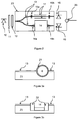
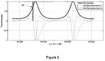
- Tuning electrodes 4 are disposed adjacent the reference Fabry-Perot etalon 3 and are used to influence its transmission characteristics in a way that a favourable operating point is established. This operating point usually is the inflexion point of the transmission function of the reference Fabry-Perot etalon 3. These electrodes 4 influence the transmission characteristics by way of an electro-optic or thermo-optical effect. Alternatively, thin film resistors or Peltier elements can be used in place of the tuning electrodes 4. These make use of a thermal or thermo-optical effect to change the transmission characteristics of the reference Fabry-Perot etalon 3 thermally.
- the light from the laser source 1 is also incident on a measurement Fabry-Perot etalon 7, which is influenced by changes in a physical parameter (for example, air pressure).
- a physical parameter for example, air pressure
- the exact manner in which the measurement Fabry-Perot etalon 7 is caused to interact with the environment so as to be influenced by the physical parameter will depend on the nature of the physical parameter. In the case of air pressure, the measurement Fabry-Perot etalon 7 will simply have a cavity that is coupled to the air through an aperture. This will become clearer below.
- the emerging light from the measurement Fabry-Perot etalon 7 is also detected by a photodetector (not shown), for example a PIN diode.
- the output signal from this photodetector will depend on the fluctuations In the physical parameter to be measured and on noise from the laser source 1.
- a difference signal between the output signal from this photodetector and the output signal from photodetector 6 is generated by a difference amplifier 8. By this means, common mode laser noise from laser source 1 is cancelled.
- the difference amplifier 8 In order to dynamically adjust the DC levels from both the reference path (i.e. through reference Fabry-Perot etalon 3 and photodetector 6) and the measurement path (i.e. through measurement Fabry-Perot etalon 7 and its photodetector), the difference amplifier 8 has a preceding gain stage where both output signals are dynamically adjusted with a long time constant.
- the light from laser source 1 may be caused to impinge on both etalons 3, 7 by way of a beam splitter. Alternatively, a double-sided emission laser source may be used.
- the tuning electrodes 4 and liquid crystal 5 are omitted.
- the laser source 1 is operated in pulses, alternating between the measurement path and the reference path such that successive pulses are incident on one or the other (but not both) of the reference and measurement Fabry-Perot etalons 3, 7. In this switching mode, the operating point can be set by adjusting the current of the laser source 1 power supply.
- the optical microphone of Figure 2 It is possible to manufacture the optical microphone of Figure 2 using silicon on insulator (SOI) techniques.
- SOI silicon on insulator
- a major advantage of the waveguide structure 13 is the possibility to integrate the reference path so that it has small physical dimensions; the reference Fabry-Perot etalon may have dimensions of typically 1 ⁇ m to 1 mm (length) and 1 ⁇ m (width).
- a laser diode with double-sided emission 30 embedded in a substrate 31 is employed.
- This laser diode 30 can be a vertical cavity surface- emitting laser (VCSEL).
- the VCSEL can either be modified by partial removal of the substrate to allow light to be emitted from both the front and the rear sides, or, a double-sided emission can be specially manufactured by omitting part of the substrate.
- Another device that can be used (again, either by modification or special manufacture) for double-sided emission Is a distributed feedback (DFB) laser diode.
- DFB distributed feedback
- the layers of the stack can consist of glass, polymer, silicon or other dielectric layers, depending on the wavelength of light emitted by laser diode 30 and the desired mechanical processing properties. Also a combination of materials in the stack is possible. The layers may be combined using bonding, gluing or other technologies.
- One of the emerging laser beams is incident on a reference path; the other laser beam, emitted from the opposite side is incident on a measurement path.
Landscapes
- Physics & Mathematics (AREA)
- General Physics & Mathematics (AREA)
- Nonlinear Science (AREA)
- Engineering & Computer Science (AREA)
- Acoustics & Sound (AREA)
- Signal Processing (AREA)
- Optics & Photonics (AREA)
- Instruments For Measurement Of Length By Optical Means (AREA)
- Length Measuring Devices By Optical Means (AREA)
- Investigating Or Analysing Materials By Optical Means (AREA)
- Mechanical Light Control Or Optical Switches (AREA)
- Spectrometry And Color Measurement (AREA)
Claims (15)
- Dispositif comprenant un interféromètre de mesure (7) et un interféromètre de référence (3), chacun étant configuré pour recevoir de la lumière à partir de la même source de lumière (1) et pour émettre de la lumière à des détecteurs respectifs (6) et ayant un point d'opération respectif, ledit interféromètre de mesure (7) est configuré pour répondre à des variations d'un paramètre physique par une variation de l'intensité de la lumière émise, alors que l'interféromètre de référence (3) est configuré pour être insensible aux variations du paramètre physique, le dispositif comprenant en outre un processeur de signaux pour la génération d'un signal différence de sortie en fonction des signaux de sortie respectifs générés par les détecteurs (6).
- Dispositif selon la revendication 1, dans lequel le processeur de signaux comprend un amplificateur de différence (8) et un étage de gain précédent pour un ajustement dynamique des niveaux en courant continu des signaux de sortie respectifs générés par les détecteurs (6).
- Dispositif selon la revendication 1 ou 2, dans lequel les interféromètres de mesure (7) et/ou de référence (3) sont des interféromètres Fabry-Perot, chacun utilisant de préférence des éléments mécaniquement rigides et/ou immobiles.
- Dispositif selon la revendication 3, dans lequel les interféromètres de mesure (7) et/ou de référence (3) comprennent une paire de miroirs espacés l'un de l'autre, de préférence des miroirs mécaniquement rigides et/ou immobiles.
- Dispositif selon l'une quelconque des revendications précédentes, comprenant en outre un élément de réglage thermique pour le réglage du point d'opération soit de l'interféromètre de mesure (7), soit de l'interféromètre de référence (3).
- Dispositif selon l'une quelconque des revendications précédentes, comprenant en outre une électrode de réglage (4) pour le réglage du point d'opération soit de l'interféromètre de mesure (7), soit de l'interféromètre de référence (3).
- Dispositif selon l'une quelconque des revendications précédentes, comprenant en outre un élément de réglage à cristaux liquides (5) disposé soit entre l'interféromètre de mesure (7), soit entre l'interféromètre de référence (3) et ses détecteurs respectifs (6).
- Dispositif selon l'une quelconque des revendications précédentes, comprenant en outre un contrôleur de source de lumière adapté pour faire en sorte que la source de lumière (1) émette de manière alternative de la lumière à une première et à une seconde longueur d'onde, les points d'opération des interféromètres de mesure (7) et de référence (3) étant atteints à la première et à la seconde longueur d'onde respectivement.
- Dispositif selon l'une quelconque des revendications précédentes, comprenant en outre un isolateur optique (2) dispose entre la source de lumière (1) et l'interféromètre de référence (3), l'isolateur optique (2) comprenant un polarisateur linéaire et une plaque de quart de longueur d'ondes.
- Dispositif selon l'une quelconque des revendications précédentes, dans lequel la source de lumière (1) est un laser.
- Dispositif selon la revendication 10, dans lequel le laser est un laser à double émission, les premier et second rayons émis étant couplés aux interféromètres de mesure (7) et de référence (3) respectivement.
- Dispositif selon la revendication 11, dans lequel le laser à double émission est une diode de laser à émission double face arrangée sur un substrat entre une première et une seconde structure de couches, chacune formant un des interféromètres de mesure (7) et de référence (3) et chacune comprenant deux couches de miroirs respectives, de préférence des couches de miroirs mécaniquement rigides et/ou des couches de miroirs immobiles, espacées à l'aide de couches d'espacement respectives et de couches de détecteur distales depuis le substrat par rapport aux couches de miroirs.
- Dispositif selon l'une quelconque des revendications précédentes, dans lequel le processeur de signaux comprend en outre un égalisateur adaptif pour égaliser l'amplitude moyenne de la sortie respective générée par les détecteurs (6) sur une période de temps d'égalisation.
- Microphone optique comprenant un dispositif selon l'une quelconque des revendications précédentes, dans lequel l'interféromètre de mesure (7) est couplé de manière acoustique avec l'environnement, l'interféromètre de référence (3) est isolé de manière acoustique de l'environnement, et le paramètre physique est la pression de l'air.
- Microphone optique selon la revendication 14, dans lequel l'interféromètre de mesure (7) est couplé de manière acoustique avec son environnement par une ouverture dans une cavité de l'interféromètre de mesure (7) .
Priority Applications (1)
| Application Number | Priority Date | Filing Date | Title |
|---|---|---|---|
| EP12722142.2A EP2710335B8 (fr) | 2011-05-16 | 2012-05-16 | Capteur optique |
Applications Claiming Priority (3)
| Application Number | Priority Date | Filing Date | Title |
|---|---|---|---|
| EP11166253A EP2525194A1 (fr) | 2011-05-16 | 2011-05-16 | Capteur optique |
| PCT/EP2012/059122 WO2012163681A1 (fr) | 2011-05-16 | 2012-05-16 | Capteur optique |
| EP12722142.2A EP2710335B8 (fr) | 2011-05-16 | 2012-05-16 | Capteur optique |
Publications (3)
| Publication Number | Publication Date |
|---|---|
| EP2710335A1 EP2710335A1 (fr) | 2014-03-26 |
| EP2710335B1 true EP2710335B1 (fr) | 2016-07-13 |
| EP2710335B8 EP2710335B8 (fr) | 2016-09-14 |
Family
ID=44588345
Family Applications (2)
| Application Number | Title | Priority Date | Filing Date |
|---|---|---|---|
| EP11166253A Withdrawn EP2525194A1 (fr) | 2011-05-16 | 2011-05-16 | Capteur optique |
| EP12722142.2A Active EP2710335B8 (fr) | 2011-05-16 | 2012-05-16 | Capteur optique |
Family Applications Before (1)
| Application Number | Title | Priority Date | Filing Date |
|---|---|---|---|
| EP11166253A Withdrawn EP2525194A1 (fr) | 2011-05-16 | 2011-05-16 | Capteur optique |
Country Status (6)
| Country | Link |
|---|---|
| US (1) | US9417147B2 (fr) |
| EP (2) | EP2525194A1 (fr) |
| JP (1) | JP6120336B2 (fr) |
| KR (1) | KR101926894B1 (fr) |
| CN (1) | CN103562684B (fr) |
| WO (1) | WO2012163681A1 (fr) |
Cited By (1)
| Publication number | Priority date | Publication date | Assignee | Title |
|---|---|---|---|---|
| DE102017205586A1 (de) | 2017-04-03 | 2018-10-04 | Robert Bosch Gmbh | Stanznietvorrichtung und Verfahren zum Überwachen einer Stanznietvorrichtung |
Families Citing this family (18)
| Publication number | Priority date | Publication date | Assignee | Title |
|---|---|---|---|---|
| EP3173781B8 (fr) | 2015-11-25 | 2024-06-12 | Xarion Laser Acoustics GmbH | Système d'essai par ultrasons en suspension dans l'air pour un objet de test |
| US10352911B2 (en) * | 2008-09-12 | 2019-07-16 | Balthasar Fischer | Airborne ultrasound testing system for a test object |
| EP2525194A1 (fr) * | 2011-05-16 | 2012-11-21 | Knowles Electronics Asia PTE. Ltd. | Capteur optique |
| CN103809281B (zh) * | 2014-02-18 | 2016-05-11 | 苏州旭创科技有限公司 | 光学标准具及其组装方法 |
| US9874518B2 (en) | 2014-04-22 | 2018-01-23 | Sharp Kabushiki Kaisha | Optical sensor system, optical gas sensor system, particulate sensor system, light emitting apparatus, and image printing apparatus |
| US10281391B2 (en) * | 2015-06-05 | 2019-05-07 | Luminit Llc | Spectrally pure short-pulse laser |
| NO343314B1 (no) * | 2015-11-29 | 2019-01-28 | Tunable As | Optisk trykksensor |
| KR101979815B1 (ko) * | 2017-08-24 | 2019-05-23 | 송광섭 | 광센서 |
| EP3677907A1 (fr) | 2019-01-04 | 2020-07-08 | Xarion Laser Acoustics GmbH | Dispositif et procédé de test d'un objet de test |
| CN109827653A (zh) * | 2019-02-28 | 2019-05-31 | 曲阜师范大学 | 一种完备光纤矢量传声器探头 |
| EP3734267A1 (fr) | 2019-05-01 | 2020-11-04 | Northrop Grumman Innovation Systems, Inc. | Dispositifs d'inspection comportant des émetteurs laser et des microphones optiques et systèmes et procédés associés |
| DE102019130696B4 (de) * | 2019-11-14 | 2022-07-07 | Carl Zeiss Smt Gmbh | Vorrichtung zur Vermessung eines Substrates und Verfahren zur Korrektur von zyklischen Fehleranteilen eines Interferometers |
| EP3825678B1 (fr) | 2019-11-22 | 2026-03-11 | Ams Ag | Appareil et procédé de détection d'objets |
| CN114868404A (zh) * | 2020-02-25 | 2022-08-05 | 松下电器(美国)知识产权公司 | 光学麦克风 |
| DE102020112495B4 (de) | 2020-05-08 | 2026-04-16 | Jenoptik Automatisierungstechnik Gmbh | Verfahren zur Prüfung einer Airbag-Abdeckung mit einer Sollbruchlinie mit definiertem Aufreißwiderstand |
| DE102020112494A1 (de) | 2020-05-08 | 2021-11-11 | Jenoptik Automatisierungstechnik Gmbh | Verfahren zur Herstellung einer Airbag-Abdeckung mit einer Sollbruchlinie mit einem definierten Aufreißwiderstand |
| CN114812627B (zh) * | 2021-01-18 | 2025-03-21 | Tdk株式会社 | 光检测元件、接收装置和光传感器装置 |
| CN114414529B (zh) * | 2021-12-07 | 2023-09-19 | 广东科学技术职业学院 | 盐度检测方法、计算机装置及计算机可读存储介质 |
Citations (1)
| Publication number | Priority date | Publication date | Assignee | Title |
|---|---|---|---|---|
| FR2765964A1 (fr) * | 1997-07-08 | 1999-01-15 | Bertin & Cie | Dispositif optique de mesure de distance avec une grande precision |
Family Cites Families (19)
| Publication number | Priority date | Publication date | Assignee | Title |
|---|---|---|---|---|
| WO1979000506A1 (fr) * | 1978-01-13 | 1979-08-09 | Nat Res Dev | Systeme interferometrique |
| JPH03146803A (ja) * | 1989-11-02 | 1991-06-21 | Kowa Co | 距離測定方法及び装置 |
| GB2314617B (en) * | 1996-06-24 | 2000-08-23 | Graviner Ltd Kidde | High sensitivity gas detection |
| JPH1163914A (ja) * | 1997-08-15 | 1999-03-05 | Nikon Corp | 光周波数領域反射光分布計測装置 |
| US7224464B2 (en) * | 1998-11-04 | 2007-05-29 | Manning Christopher J | Fourier-transform spectrometers |
| CN100465595C (zh) * | 2000-04-24 | 2009-03-04 | 周晟 | 相位差测量装置及应用该装置的外差干涉测量系统 |
| JP3605010B2 (ja) * | 2000-08-08 | 2004-12-22 | 株式会社ミツトヨ | 表面性状測定器 |
| US7224465B2 (en) * | 2002-10-15 | 2007-05-29 | University Of Maryland | Fiber tip based sensor system for measurements of pressure gradient, air particle velocity and acoustic intensity |
| US7561276B2 (en) * | 2006-01-13 | 2009-07-14 | Luna Innovations Incorporated | Demodulation method and apparatus for fiber optic sensors |
| US7355723B2 (en) * | 2006-03-02 | 2008-04-08 | Symphony Acoustics, Inc. | Apparatus comprising a high-signal-to-noise displacement sensor and method therefore |
| US7583390B2 (en) * | 2006-03-02 | 2009-09-01 | Symphony Acoustics, Inc. | Accelerometer comprising an optically resonant cavity |
| CN102973243B (zh) * | 2007-01-10 | 2015-11-25 | 光学实验室成像公司 | 用于扫频源光学相干断层的方法和装置 |
| US8007609B2 (en) * | 2007-10-31 | 2011-08-30 | Symphony Acoustics, Inc. | Parallel plate arrangement and method of formation |
| AU2008325237B2 (en) * | 2007-11-05 | 2014-05-01 | Biosensor, Inc. | Optical sensor for determining the concentration of an analyte |
| JP2009231316A (ja) * | 2008-03-19 | 2009-10-08 | Nec Corp | Ldモジュール |
| CN102150439B (zh) * | 2008-09-12 | 2015-04-22 | 楼氏电子亚洲有限公司 | 换能器系统装置及方法 |
| GB0900705D0 (en) * | 2009-01-16 | 2009-03-04 | Univ Huddersfield | Surface measurement system |
| CN101718520B (zh) * | 2009-11-16 | 2011-01-05 | 浙江大学 | 一种快速表面质量测量系统 |
| EP2525194A1 (fr) * | 2011-05-16 | 2012-11-21 | Knowles Electronics Asia PTE. Ltd. | Capteur optique |
-
2011
- 2011-05-16 EP EP11166253A patent/EP2525194A1/fr not_active Withdrawn
-
2012
- 2012-05-16 EP EP12722142.2A patent/EP2710335B8/fr active Active
- 2012-05-16 KR KR1020137030900A patent/KR101926894B1/ko active Active
- 2012-05-16 JP JP2014510796A patent/JP6120336B2/ja active Active
- 2012-05-16 CN CN201280022889.2A patent/CN103562684B/zh active Active
- 2012-05-16 WO PCT/EP2012/059122 patent/WO2012163681A1/fr not_active Ceased
- 2012-05-16 US US14/117,445 patent/US9417147B2/en active Active
Patent Citations (1)
| Publication number | Priority date | Publication date | Assignee | Title |
|---|---|---|---|---|
| FR2765964A1 (fr) * | 1997-07-08 | 1999-01-15 | Bertin & Cie | Dispositif optique de mesure de distance avec une grande precision |
Cited By (1)
| Publication number | Priority date | Publication date | Assignee | Title |
|---|---|---|---|---|
| DE102017205586A1 (de) | 2017-04-03 | 2018-10-04 | Robert Bosch Gmbh | Stanznietvorrichtung und Verfahren zum Überwachen einer Stanznietvorrichtung |
Also Published As
| Publication number | Publication date |
|---|---|
| KR101926894B1 (ko) | 2018-12-07 |
| US20150139451A1 (en) | 2015-05-21 |
| JP6120336B2 (ja) | 2017-04-26 |
| EP2710335B8 (fr) | 2016-09-14 |
| WO2012163681A1 (fr) | 2012-12-06 |
| EP2710335A1 (fr) | 2014-03-26 |
| CN103562684B (zh) | 2016-10-12 |
| US9417147B2 (en) | 2016-08-16 |
| CN103562684A (zh) | 2014-02-05 |
| JP2014515114A (ja) | 2014-06-26 |
| EP2525194A1 (fr) | 2012-11-21 |
| KR20140040720A (ko) | 2014-04-03 |
Similar Documents
| Publication | Publication Date | Title |
|---|---|---|
| EP2710335B1 (fr) | Capteur optique | |
| US7359067B2 (en) | Optical displacement sensor comprising a wavelength-tunable optical source | |
| CN102150439B (zh) | 换能器系统装置及方法 | |
| US8369367B1 (en) | Tunable laser system | |
| US6594022B1 (en) | Wavelength reference device | |
| WO2003003082A1 (fr) | Capteur de deplacement optique | |
| JP2002006238A (ja) | ファブリ・ペロー共振器用中空構造体 | |
| EP3223540B1 (fr) | Système de microphone optique | |
| WO2007143362A2 (fr) | Capteur de déplacement amélioré | |
| CA2665527A1 (fr) | Procede et dispositif permettant de reduire le bruit de phase d'un laser | |
| CA2385905A1 (fr) | Generateur de reference de longueur d'onde | |
| US6580516B1 (en) | Tunable Fabry Perot microelectromechanical resonator adapted for optical filters and lasers with reduced optical power-dependent tuning | |
| EP2389014A1 (fr) | Microphone | |
| KR101979815B1 (ko) | 광센서 | |
| JP2016143716A (ja) | 波長制御用モニタ、光モジュール、波長モニタ方法 | |
| Fischer et al. | Sound recording by laser interferometry |
Legal Events
| Date | Code | Title | Description |
|---|---|---|---|
| PUAI | Public reference made under article 153(3) epc to a published international application that has entered the european phase |
Free format text: ORIGINAL CODE: 0009012 |
|
| 17P | Request for examination filed |
Effective date: 20131216 |
|
| AK | Designated contracting states |
Kind code of ref document: A1 Designated state(s): AL AT BE BG CH CY CZ DE DK EE ES FI FR GB GR HR HU IE IS IT LI LT LU LV MC MK MT NL NO PL PT RO RS SE SI SK SM TR |
|
| DAX | Request for extension of the european patent (deleted) | ||
| 17Q | First examination report despatched |
Effective date: 20150701 |
|
| GRAP | Despatch of communication of intention to grant a patent |
Free format text: ORIGINAL CODE: EPIDOSNIGR1 |
|
| RIC1 | Information provided on ipc code assigned before grant |
Ipc: H04R 23/00 20060101ALI20160205BHEP Ipc: G01B 9/02 20060101ALI20160205BHEP Ipc: G01D 5/26 20060101AFI20160205BHEP Ipc: G02F 1/21 20060101ALI20160205BHEP Ipc: G01L 11/02 20060101ALI20160205BHEP |
|
| INTG | Intention to grant announced |
Effective date: 20160224 |
|
| GRAS | Grant fee paid |
Free format text: ORIGINAL CODE: EPIDOSNIGR3 |
|
| GRAA | (expected) grant |
Free format text: ORIGINAL CODE: 0009210 |
|
| AK | Designated contracting states |
Kind code of ref document: B1 Designated state(s): AL AT BE BG CH CY CZ DE DK EE ES FI FR GB GR HR HU IE IS IT LI LT LU LV MC MK MT NL NO PL PT RO RS SE SI SK SM TR |
|
| REG | Reference to a national code |
Ref country code: GB Ref legal event code: FG4D |
|
| REG | Reference to a national code |
Ref country code: AT Ref legal event code: REF Ref document number: 812712 Country of ref document: AT Kind code of ref document: T Effective date: 20160715 Ref country code: CH Ref legal event code: EP |
|
| RAP2 | Party data changed (patent owner data changed or rights of a patent transferred) |
Owner name: XARION LASER ACOUSTICS GMBH |
|
| REG | Reference to a national code |
Ref country code: IE Ref legal event code: FG4D |
|
| REG | Reference to a national code |
Ref country code: DE Ref legal event code: R096 Ref document number: 602012020426 Country of ref document: DE |
|
| REG | Reference to a national code |
Ref country code: CH Ref legal event code: NV Representative=s name: ROSENICH PAUL; KUENSCH JOACHIM PATENTBUERO PAU, LI |
|
| REG | Reference to a national code |
Ref country code: LT Ref legal event code: MG4D |
|
| REG | Reference to a national code |
Ref country code: NL Ref legal event code: MP Effective date: 20160713 |
|
| PG25 | Lapsed in a contracting state [announced via postgrant information from national office to epo] |
Ref country code: HR Free format text: LAPSE BECAUSE OF FAILURE TO SUBMIT A TRANSLATION OF THE DESCRIPTION OR TO PAY THE FEE WITHIN THE PRESCRIBED TIME-LIMIT Effective date: 20160713 Ref country code: NL Free format text: LAPSE BECAUSE OF FAILURE TO SUBMIT A TRANSLATION OF THE DESCRIPTION OR TO PAY THE FEE WITHIN THE PRESCRIBED TIME-LIMIT Effective date: 20160713 Ref country code: IT Free format text: LAPSE BECAUSE OF FAILURE TO SUBMIT A TRANSLATION OF THE DESCRIPTION OR TO PAY THE FEE WITHIN THE PRESCRIBED TIME-LIMIT Effective date: 20160713 Ref country code: FI Free format text: LAPSE BECAUSE OF FAILURE TO SUBMIT A TRANSLATION OF THE DESCRIPTION OR TO PAY THE FEE WITHIN THE PRESCRIBED TIME-LIMIT Effective date: 20160713 Ref country code: LT Free format text: LAPSE BECAUSE OF FAILURE TO SUBMIT A TRANSLATION OF THE DESCRIPTION OR TO PAY THE FEE WITHIN THE PRESCRIBED TIME-LIMIT Effective date: 20160713 Ref country code: NO Free format text: LAPSE BECAUSE OF FAILURE TO SUBMIT A TRANSLATION OF THE DESCRIPTION OR TO PAY THE FEE WITHIN THE PRESCRIBED TIME-LIMIT Effective date: 20161013 Ref country code: RS Free format text: LAPSE BECAUSE OF FAILURE TO SUBMIT A TRANSLATION OF THE DESCRIPTION OR TO PAY THE FEE WITHIN THE PRESCRIBED TIME-LIMIT Effective date: 20160713 Ref country code: IS Free format text: LAPSE BECAUSE OF FAILURE TO SUBMIT A TRANSLATION OF THE DESCRIPTION OR TO PAY THE FEE WITHIN THE PRESCRIBED TIME-LIMIT Effective date: 20161113 |
|
| PG25 | Lapsed in a contracting state [announced via postgrant information from national office to epo] |
Ref country code: ES Free format text: LAPSE BECAUSE OF FAILURE TO SUBMIT A TRANSLATION OF THE DESCRIPTION OR TO PAY THE FEE WITHIN THE PRESCRIBED TIME-LIMIT Effective date: 20160713 Ref country code: GR Free format text: LAPSE BECAUSE OF FAILURE TO SUBMIT A TRANSLATION OF THE DESCRIPTION OR TO PAY THE FEE WITHIN THE PRESCRIBED TIME-LIMIT Effective date: 20161014 Ref country code: SE Free format text: LAPSE BECAUSE OF FAILURE TO SUBMIT A TRANSLATION OF THE DESCRIPTION OR TO PAY THE FEE WITHIN THE PRESCRIBED TIME-LIMIT Effective date: 20160713 Ref country code: PT Free format text: LAPSE BECAUSE OF FAILURE TO SUBMIT A TRANSLATION OF THE DESCRIPTION OR TO PAY THE FEE WITHIN THE PRESCRIBED TIME-LIMIT Effective date: 20161114 Ref country code: PL Free format text: LAPSE BECAUSE OF FAILURE TO SUBMIT A TRANSLATION OF THE DESCRIPTION OR TO PAY THE FEE WITHIN THE PRESCRIBED TIME-LIMIT Effective date: 20160713 Ref country code: BE Free format text: LAPSE BECAUSE OF FAILURE TO SUBMIT A TRANSLATION OF THE DESCRIPTION OR TO PAY THE FEE WITHIN THE PRESCRIBED TIME-LIMIT Effective date: 20160713 Ref country code: LV Free format text: LAPSE BECAUSE OF FAILURE TO SUBMIT A TRANSLATION OF THE DESCRIPTION OR TO PAY THE FEE WITHIN THE PRESCRIBED TIME-LIMIT Effective date: 20160713 |
|
| REG | Reference to a national code |
Ref country code: DE Ref legal event code: R097 Ref document number: 602012020426 Country of ref document: DE |
|
| PG25 | Lapsed in a contracting state [announced via postgrant information from national office to epo] |
Ref country code: EE Free format text: LAPSE BECAUSE OF FAILURE TO SUBMIT A TRANSLATION OF THE DESCRIPTION OR TO PAY THE FEE WITHIN THE PRESCRIBED TIME-LIMIT Effective date: 20160713 Ref country code: RO Free format text: LAPSE BECAUSE OF FAILURE TO SUBMIT A TRANSLATION OF THE DESCRIPTION OR TO PAY THE FEE WITHIN THE PRESCRIBED TIME-LIMIT Effective date: 20160713 |
|
| PLBE | No opposition filed within time limit |
Free format text: ORIGINAL CODE: 0009261 |
|
| STAA | Information on the status of an ep patent application or granted ep patent |
Free format text: STATUS: NO OPPOSITION FILED WITHIN TIME LIMIT |
|
| PG25 | Lapsed in a contracting state [announced via postgrant information from national office to epo] |
Ref country code: CZ Free format text: LAPSE BECAUSE OF FAILURE TO SUBMIT A TRANSLATION OF THE DESCRIPTION OR TO PAY THE FEE WITHIN THE PRESCRIBED TIME-LIMIT Effective date: 20160713 Ref country code: SM Free format text: LAPSE BECAUSE OF FAILURE TO SUBMIT A TRANSLATION OF THE DESCRIPTION OR TO PAY THE FEE WITHIN THE PRESCRIBED TIME-LIMIT Effective date: 20160713 Ref country code: DK Free format text: LAPSE BECAUSE OF FAILURE TO SUBMIT A TRANSLATION OF THE DESCRIPTION OR TO PAY THE FEE WITHIN THE PRESCRIBED TIME-LIMIT Effective date: 20160713 Ref country code: BG Free format text: LAPSE BECAUSE OF FAILURE TO SUBMIT A TRANSLATION OF THE DESCRIPTION OR TO PAY THE FEE WITHIN THE PRESCRIBED TIME-LIMIT Effective date: 20161013 Ref country code: SK Free format text: LAPSE BECAUSE OF FAILURE TO SUBMIT A TRANSLATION OF THE DESCRIPTION OR TO PAY THE FEE WITHIN THE PRESCRIBED TIME-LIMIT Effective date: 20160713 |
|
| 26N | No opposition filed |
Effective date: 20170418 |
|
| PG25 | Lapsed in a contracting state [announced via postgrant information from national office to epo] |
Ref country code: SI Free format text: LAPSE BECAUSE OF FAILURE TO SUBMIT A TRANSLATION OF THE DESCRIPTION OR TO PAY THE FEE WITHIN THE PRESCRIBED TIME-LIMIT Effective date: 20160713 Ref country code: LU Free format text: LAPSE BECAUSE OF NON-PAYMENT OF DUE FEES Effective date: 20170531 |
|
| PG25 | Lapsed in a contracting state [announced via postgrant information from national office to epo] |
Ref country code: MC Free format text: LAPSE BECAUSE OF FAILURE TO SUBMIT A TRANSLATION OF THE DESCRIPTION OR TO PAY THE FEE WITHIN THE PRESCRIBED TIME-LIMIT Effective date: 20160713 |
|
| REG | Reference to a national code |
Ref country code: IE Ref legal event code: MM4A |
|
| REG | Reference to a national code |
Ref country code: FR Ref legal event code: ST Effective date: 20180131 |
|
| PG25 | Lapsed in a contracting state [announced via postgrant information from national office to epo] |
Ref country code: LU Free format text: LAPSE BECAUSE OF NON-PAYMENT OF DUE FEES Effective date: 20170516 |
|
| PG25 | Lapsed in a contracting state [announced via postgrant information from national office to epo] |
Ref country code: IE Free format text: LAPSE BECAUSE OF NON-PAYMENT OF DUE FEES Effective date: 20170516 |
|
| PG25 | Lapsed in a contracting state [announced via postgrant information from national office to epo] |
Ref country code: FR Free format text: LAPSE BECAUSE OF NON-PAYMENT OF DUE FEES Effective date: 20170531 |
|
| PG25 | Lapsed in a contracting state [announced via postgrant information from national office to epo] |
Ref country code: MT Free format text: LAPSE BECAUSE OF NON-PAYMENT OF DUE FEES Effective date: 20170516 |
|
| PG25 | Lapsed in a contracting state [announced via postgrant information from national office to epo] |
Ref country code: AL Free format text: LAPSE BECAUSE OF FAILURE TO SUBMIT A TRANSLATION OF THE DESCRIPTION OR TO PAY THE FEE WITHIN THE PRESCRIBED TIME-LIMIT Effective date: 20160713 |
|
| PG25 | Lapsed in a contracting state [announced via postgrant information from national office to epo] |
Ref country code: HU Free format text: LAPSE BECAUSE OF FAILURE TO SUBMIT A TRANSLATION OF THE DESCRIPTION OR TO PAY THE FEE WITHIN THE PRESCRIBED TIME-LIMIT; INVALID AB INITIO Effective date: 20120516 |
|
| PG25 | Lapsed in a contracting state [announced via postgrant information from national office to epo] |
Ref country code: CY Free format text: LAPSE BECAUSE OF NON-PAYMENT OF DUE FEES Effective date: 20160713 |
|
| PG25 | Lapsed in a contracting state [announced via postgrant information from national office to epo] |
Ref country code: MK Free format text: LAPSE BECAUSE OF FAILURE TO SUBMIT A TRANSLATION OF THE DESCRIPTION OR TO PAY THE FEE WITHIN THE PRESCRIBED TIME-LIMIT Effective date: 20160713 |
|
| PG25 | Lapsed in a contracting state [announced via postgrant information from national office to epo] |
Ref country code: TR Free format text: LAPSE BECAUSE OF FAILURE TO SUBMIT A TRANSLATION OF THE DESCRIPTION OR TO PAY THE FEE WITHIN THE PRESCRIBED TIME-LIMIT Effective date: 20160713 |
|
| REG | Reference to a national code |
Ref country code: AT Ref legal event code: UEP Ref document number: 812712 Country of ref document: AT Kind code of ref document: T Effective date: 20160713 |
|
| REG | Reference to a national code |
Ref country code: CH Ref legal event code: PCAR Free format text: NEW ADDRESS: ROTENBODENSTRASSE 12, 9497 TRIESENBERG (LI) |
|
| REG | Reference to a national code |
Ref country code: DE Ref legal event code: R082 Ref document number: 602012020426 Country of ref document: DE Representative=s name: VOSSIUS & PARTNER PATENTANWAELTE RECHTSANWAELT, DE Ref country code: DE Ref legal event code: R082 Ref document number: 602012020426 Country of ref document: DE Representative=s name: NEUHOLD, ALFRED, DR.TECHN., CH Ref country code: DE Ref legal event code: R082 Ref document number: 602012020426 Country of ref document: DE Representative=s name: NEUHOLD, ALFRED, DR.TECHN., LI |
|
| P01 | Opt-out of the competence of the unified patent court (upc) registered |
Effective date: 20230515 |
|
| REG | Reference to a national code |
Ref country code: DE Ref legal event code: R082 Ref document number: 602012020426 Country of ref document: DE Representative=s name: NEUHOLD, ALFRED, DR.TECHN., CH Ref country code: DE Ref legal event code: R082 Ref document number: 602012020426 Country of ref document: DE Representative=s name: NEUHOLD, ALFRED, DR.TECHN., LI |
|
| PGFP | Annual fee paid to national office [announced via postgrant information from national office to epo] |
Ref country code: DE Payment date: 20250521 Year of fee payment: 14 |
|
| PGFP | Annual fee paid to national office [announced via postgrant information from national office to epo] |
Ref country code: GB Payment date: 20250521 Year of fee payment: 14 |
|
| PGFP | Annual fee paid to national office [announced via postgrant information from national office to epo] |
Ref country code: CH Payment date: 20250601 Year of fee payment: 14 |
|
| PGFP | Annual fee paid to national office [announced via postgrant information from national office to epo] |
Ref country code: AT Payment date: 20250522 Year of fee payment: 14 |