EP2710364B1 - Dispositif et procédé de détermination des caractéristiques d'un milieu - Google Patents
Dispositif et procédé de détermination des caractéristiques d'un milieu Download PDFInfo
- Publication number
- EP2710364B1 EP2710364B1 EP12727614.5A EP12727614A EP2710364B1 EP 2710364 B1 EP2710364 B1 EP 2710364B1 EP 12727614 A EP12727614 A EP 12727614A EP 2710364 B1 EP2710364 B1 EP 2710364B1
- Authority
- EP
- European Patent Office
- Prior art keywords
- carrier
- medium
- waves
- transmitter
- receiver
- Prior art date
- Legal status (The legal status is an assumption and is not a legal conclusion. Google has not performed a legal analysis and makes no representation as to the accuracy of the status listed.)
- Active
Links
Images
Classifications
-
- G—PHYSICS
- G01—MEASURING; TESTING
- G01N—INVESTIGATING OR ANALYSING MATERIALS BY DETERMINING THEIR CHEMICAL OR PHYSICAL PROPERTIES
- G01N29/00—Investigating or analysing materials by the use of ultrasonic, sonic or infrasonic waves; Visualisation of the interior of objects by transmitting ultrasonic or sonic waves through the object
- G01N29/02—Analysing fluids
- G01N29/022—Fluid sensors based on microsensors, e.g. quartz crystal-microbalance [QCM], surface acoustic wave [SAW] devices, tuning forks, cantilevers, flexural plate wave [FPW] devices
-
- G—PHYSICS
- G01—MEASURING; TESTING
- G01N—INVESTIGATING OR ANALYSING MATERIALS BY DETERMINING THEIR CHEMICAL OR PHYSICAL PROPERTIES
- G01N29/00—Investigating or analysing materials by the use of ultrasonic, sonic or infrasonic waves; Visualisation of the interior of objects by transmitting ultrasonic or sonic waves through the object
- G01N29/22—Details, e.g. general constructional or apparatus details
- G01N29/32—Arrangements for suppressing undesired influences, e.g. temperature or pressure variations, compensating for signal noise
-
- G—PHYSICS
- G01—MEASURING; TESTING
- G01N—INVESTIGATING OR ANALYSING MATERIALS BY DETERMINING THEIR CHEMICAL OR PHYSICAL PROPERTIES
- G01N29/00—Investigating or analysing materials by the use of ultrasonic, sonic or infrasonic waves; Visualisation of the interior of objects by transmitting ultrasonic or sonic waves through the object
- G01N29/02—Analysing fluids
- G01N29/032—Analysing fluids by measuring attenuation of acoustic waves
-
- G—PHYSICS
- G01—MEASURING; TESTING
- G01N—INVESTIGATING OR ANALYSING MATERIALS BY DETERMINING THEIR CHEMICAL OR PHYSICAL PROPERTIES
- G01N29/00—Investigating or analysing materials by the use of ultrasonic, sonic or infrasonic waves; Visualisation of the interior of objects by transmitting ultrasonic or sonic waves through the object
- G01N29/22—Details, e.g. general constructional or apparatus details
- G01N29/24—Probes
- G01N29/2462—Probes with waveguides, e.g. SAW devices
-
- G—PHYSICS
- G01—MEASURING; TESTING
- G01N—INVESTIGATING OR ANALYSING MATERIALS BY DETERMINING THEIR CHEMICAL OR PHYSICAL PROPERTIES
- G01N2291/00—Indexing codes associated with group G01N29/00
- G01N2291/02—Indexing codes associated with the analysed material
- G01N2291/028—Material parameters
- G01N2291/02818—Density, viscosity
-
- G—PHYSICS
- G01—MEASURING; TESTING
- G01N—INVESTIGATING OR ANALYSING MATERIALS BY DETERMINING THEIR CHEMICAL OR PHYSICAL PROPERTIES
- G01N2291/00—Indexing codes associated with group G01N29/00
- G01N2291/02—Indexing codes associated with the analysed material
- G01N2291/028—Material parameters
- G01N2291/02881—Temperature
-
- G—PHYSICS
- G01—MEASURING; TESTING
- G01N—INVESTIGATING OR ANALYSING MATERIALS BY DETERMINING THEIR CHEMICAL OR PHYSICAL PROPERTIES
- G01N2291/00—Indexing codes associated with group G01N29/00
- G01N2291/04—Wave modes and trajectories
- G01N2291/042—Wave modes
- G01N2291/0423—Surface waves, e.g. Rayleigh waves, Love waves
-
- G—PHYSICS
- G01—MEASURING; TESTING
- G01N—INVESTIGATING OR ANALYSING MATERIALS BY DETERMINING THEIR CHEMICAL OR PHYSICAL PROPERTIES
- G01N2291/00—Indexing codes associated with group G01N29/00
- G01N2291/04—Wave modes and trajectories
- G01N2291/042—Wave modes
- G01N2291/0427—Flexural waves, plate waves, e.g. Lamb waves, tuning fork, cantilever
Definitions
- the invention relates to a device for determining properties of a medium according to claim 1 and to a method for producing such a device according to claim 6.
- WO 2008/034878 a device for exciting surface acoustic waves in a carrier adjacent to the medium to be examined, wherein physical and / or chemical properties of the medium are determined with the aid of the surface sound waves.
- the US 2009/0114798 A1 describes a device with a transmitter and a receiver, which are arranged on a common carrier in the form of a Si substrate. On the Si substrate, an absorption region consisting of a polysilicon layer and two metal layers is arranged.
- a sensor which comprises an acoustic resonator with an upper and a lower electrode.
- the problem underlying the invention is to provide a device for determining properties of a medium, which allows the most efficient investigation of the medium. Furthermore, a method for producing such a device is to be specified.
- the carrier of the device has a first surface, with which it is to be brought into contact with the medium, and a second surface, which faces away from the first surface, wherein the transmitter and the first and the second material region arranged on the second surface are.
- the first and second material regions ensure that propagation of the sound waves in an undesired direction and thus, for example, reflections on other structures of the device and thus echoes in the receiver signal are suppressed or at least reduced.
- external disturbances can be damped, the signal-to-noise ratio of the receiver signal can be increased, and / or the dependence of the receiver signal on properties of the medium can be linearized.
- the first and the second material region can mechanically stabilize the device and counteract, for example, also a fogging on the carrier and / or the transmitter or the receiver.
- the transmitter is adapted to receive in the carrier surface acoustic waves, e.g. in the form of Lamb waves or in the form of a hybrid of Lamb and Rayleigh waves.
- surface acoustic wave pulses are generated in the carrier.
- the surface acoustic waves excited in the carrier partially couple out of the carrier into the medium, i. there is an at least partial conversion of the surface acoustic waves in the carrier in volume sound waves in the medium.
- the volume sound waves excited in the medium are partly reconverted back into surface sound waves in the carrier, which can then be registered with the receiver.
- part of the surface acoustic waves excited in the carrier will also pass directly in the carrier to the receiver and be detected there.
- At least one of the two material regions may be arranged to promote conversion of sound waves excited in the carrier into bulk sound waves in the medium, i. a greater proportion of the sound waves in the carrier decouples in the medium than would be the case without the material areas.
- the material regions are formed such that, on the one hand, the first material region favors the coupling of sound waves from the carrier into the medium and, on the other hand, the more strongly absorbing second material region attenuates decoupling from the carrier in one direction away from the medium.
- the first material region can be designed so that it promotes the excitation of a specific type of sound waves, ie sound waves with a specific longitudinal and transverse component.
- the first material region and / or the second material region is designed such that surface waves or creeping waves are preferably excited in the carrier.
- the first and / or the second material region is formed such that in the carrier at a first frequency (or a first frequency range) a first mode (eg surface waves) and at a second frequency (or a second frequency range ) a second wave type (eg creeping waves) is excited.
- the first material region is also designed such that it reflects sound waves with the frequency of the waves excited in the carrier stronger than the second material region.
- the higher-reflecting first material region is arranged at least in sections between the carrier and the second material region, wherein the two material regions are arranged in particular on a side of the carrier which faces away from the medium to be examined during operation of the device.
- the higher-reflective first material region counteracts the escape of acoustic waves from the carrier via a surface of the carrier facing away from the medium and, in particular, as mentioned above, promotes the coupling of waves into the medium, i. the conversion of acoustic waves excited in the carrier into volume sound waves in the medium, stronger than the second material region.
- the first material region can reflect sound waves more strongly in a first frequency range than in a second frequency range, so that in the first frequency range a larger proportion of the sound waves excited in the carrier will couple into the medium than in the second frequency range, i. the conversion of sound waves in the carrier into volume sound waves is frequency dependent, or the frequency dependence of the conversion is changed (e.g., amplified), as mentioned above. Also, by the frequency dependence of the reflection behavior of the first material region, a frequency-dependent excitation of a certain type of bet in the carrier can take place, as also mentioned above.
- the characteristics of the acoustic waves detected by the receiver i.
- surface sound waves generated by re-conversion of volume sound waves or, on the other hand, surface sound waves traveling directly in the carrier from the transmitter to the receiver depend on properties of the medium (for example its composition, mass density and / or temperature).
- the (electrical) receiver signal also depends on the properties of the medium, so that properties of the medium can be determined by analysis of the receiver signal.
- the transit time and the amplitude of the surface sound waves arriving at the receiver depend on properties of the medium.
- the device according to the invention thus constitutes a sensor used in particular for determining properties of a medium in the form of a liquid and / or a soft material (for example a biological tissue or a gel) can.
- a medium in the form of a gas for example, the device is partially or completely submerged in the medium or connected to a reservoir filled with the medium or a line through which the medium flows so that the medium can flow through the device.
- properties of the medium can be continuously monitored in order to determine time-dependent properties ("monitoring").
- a spatially resolved measurement of a spatially inhomogeneously distributed property of the medium is possible.
- the support is, for example, a substantially planar (plate-like), in particular at least substantially rigid, structure, wherein the support can also be formed from a plurality of parts elements, for example a plurality of spaced-apart plates.
- the carrier may also be integrally formed.
- the support is a spatial structure, for example a hollow cylinder.
- the carrier as a hollow cylinder of the carrier forms a lateral surface which limits a fillable with the medium to be examined inner volume.
- a portion of the carrier adjacent to the medium itself may have a cavity in which the transmitter and / or the receiver are located.
- the carrier as a hollow cylinder
- the wall of the hollow cylinder or in a plate as a carrier the plate having the cavity.
- the cavity formed by a portion of the support is limited by an inner wall that is in physical contact with the medium upon operation of the device with an inner side and an outer wall that forms an outer surface of the device.
- the first and / or the second material region are also arranged in this cavity.
- the first material region comprises a first material and the second material region comprises a second material, wherein the second material has a greater mass density than the first material. Furthermore, it is conceivable that the second material region has a higher acoustic impedance than the first material region, wherein the "acoustic impedance" is understood in particular to be the quotient of sound pressure and sound flow.
- the first and second material regions comprise at least one material that is in its solid state, i. the first and second material regions are not formed exclusively by a gas (air).
- the first material region for example, a foam-like material (for example, polyurethane foam) comes into question.
- a foam-like material for example, polyurethane foam
- the material for the second material region e.g. Silicone or epoxy resin used.
- the material of the first material region and / or the material of the second material region may be a filling, e.g. Air bubbles and / or metal particles.
- the properties of the first and / or the second material region are specifically adapted via the type (for example the size of the metal particles) and / or the concentration of the filling.
- the first and / or the second material region in a first frequency range more strongly promotes the conversion of sound waves excited in the carrier into volume sound waves in the medium (eg sound waves more strongly reflected in this frequency range).
- a second frequency range e.g. the conversion in the second frequency range is suppressed.
- a certain type of wave is preferably excited.
- the first material region prefferably has a lacquer or a metallic coating which, for example, can simultaneously be used as a conductor for contacting components (for example of the transmitter and / or the receiver).
- the carrier of the device has a first surface, with which it is to be brought into contact with the medium, and a second surface, that of the first Surface facing away, wherein the transmitter and the first and the second material region are arranged on the second surface.
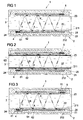
- the illustrated device 1 has a carrier in the form of a hollow cylinder 2, wherein an inner surface 22 of a shell 21 of the hollow cylinder 2 defines an inner volume 23 of the device 1.
- an inner volume 23 is a medium in the form of a liquid 3, wherein chemical and / or physical properties of the liquid 3 with the aid of the device 1 according to the invention can be determined.
- the hollow cylinder 2 is in particular formed of a non-piezoelectric material (eg a metal or a plastic).
- the jacket 21 of the hollow cylinder 2 is at least partially formed as a hollow body, wherein a first (inner) portion 211 of the shell 21, which forms the mentioned inner surface 22, a cavity 24 to the inner volume 23 out and a second (outer) portion 212 the Cavity 24 limited to the outside.
- Part of the surface acoustic waves A excited in the section 211 will decouple into the liquid 3, i. in volume sound waves B in the liquid.
- a part of these volume sound waves B is in turn connected to another, e.g. the transmitter 4 is reflected in a direction perpendicular to the direction of propagation A of the surface waves (i.e., radially) opposed portion of the inner portion 211, and another portion is converted back to surface acoustic waves A 'in the carrier.
- These surface acoustic waves A ' are detected by a receiver 5, wherein the receiver 5 is also arranged on a side facing away from the cavity 24 of the inner portion 211.
- the receiver 5 is disposed at a portion of the inner portion 211 radially opposite to the portion of the inner portion 211 with the transmitter 4.
- the receiver 5 is placed elsewhere, for. B. so that it lies with the transmitter 4 on a common straight line which extends along the longitudinal axis of the hollow cylinder 2.
- the z. B. is disposed on the same portion of the inner portion 211 as the transmitter 4, e.g. with the transmitter 4 is at least approximately on a common line along the longitudinal axis of the hollow cylinder 2.
- Part of the surface acoustic waves excited by the transmitter 4 in the inner portion 211 will also pass directly to the receiver 5, ie via the inner portion 211 of the hollow cylinder 2, so that the signal produced by the receiver will well contain a fraction which is on the surface acoustic waves A 'produced by mode-back conversion is due, as well as a component which is generated upon receipt of surface acoustic waves which pass directly from the transmitter 4 to the receiver 5.
- Both parts of the receiver signal are dependent on properties of the liquid 3, so that it is possible to deduce the properties of the liquid by evaluating the signal components.
- first and a second material region in the form of a first potting 61 and a second potting 62.
- the first potting 61 is disposed directly on the surface 25 of the first portion 211 of the shell 21, while the second potting 62 is only partially in contact with the first section 211. Otherwise, the second potting 62 extends between the first potting 61 and the outer portion 212 of the shell 21, wherein he both the transmitter 4 and the receiver 6 on a the first portion 211 of the hollow cylinder 2 facing away from the rear side and laterally on one of the first Potting 61 facing away from the side.
- the second encapsulation 62 is made of a material which absorbs sound waves having a frequency of the excited surface acoustic waves A more strongly than the first encapsulation 61. At the same time, the material of the first encapsulation 61 reflects the surface acoustic waves A more strongly than the material of the second encapsulation 62.
- the first and second potting 61, 62 thus prevent unwanted outcoupling of the surface acoustic waves A away from the liquid 3 (i.e., into the cavity 24) or attenuate surface acoustic waves propagating in the hollow cylinder 2 along at least one undesired propagation path.
- a reproducible state of the backside i.e., outer surface 25
- is realized which is as independent as possible from external influences i.e., the environment of device 1).
- the first potting 61 may be such that it influences the conversion of acoustic waves excited in the hollow cylinder 2 (eg, depending on location), as explained above. It is also possible for the first potting 61 to be designed so that a specific type of shaft (eg the surface waves mentioned) is preferably excited in the hollow cylinder 2 (eg exclusively). In particular, the first encapsulation is such (by choice of material and / or dimensions) that the type of excited waves depends on the excitation frequency of the transmitter.
- the first encapsulation 61 promotes the excitation of a first mode (eg surface waves) and in a second frequency range the excitation of a second mode (eg creeping waves that propagate mainly or exclusively in the wall of the hollow cylinder 2).
- a wave type is "favored" means, in particular, that the effective sound refractive index of the Hollow cylinder 2 is changed by the first potting 61 so that only or predominantly the desired wave type can propagate in the hollow cylinder.
- first and the second potting 61, 62 may be structured (eg, strip-shaped) to impart a desired direction of propagation to the surface acoustic waves A.
- the second potting 62 has a greater thickness (perpendicular to the first portion 211 of the carrier 2) than the first potting 61.
- the encapsulants 61, 62 may each be continuous, i. extending continuously from the region of the first portion 211 of the hollow cylinder 2, on which the transmitter 4 is arranged, to the region of the first portion 211 of the hollow cylinder 2 with the receiver 5.
- the first and second potting 61, 62 extend along the entire inner periphery of the first portion 211 of the carrier 2.
- the first and / or the second potting 61, 62 form a plurality of spaced-apart portions.
- FIG. 2 shows a sectional view of a device 1 according to a second embodiment of the invention.
- a further material region in the form of a coating 63 on the inner side 22 of the inner portion 211 of the shell 21 arranged in addition.
- the coating 63 has an acoustic impedance which is greater than the acoustic impedance of the liquid 3 to be examined and smaller than the acoustic impedance of the hollow cylinder 2, ie the inner portion 211.
- the coating 63 is patterned corresponding to the first and the second encapsulation 61, 62 in order to support a guidance of the surface acoustic waves A.
- the coating has 63 a plurality of spaced-apart portions.
- the coating 63 is formed continuously and, for example, extends at least with a partial section along the entire inner circumference of the first section 211 of the hollow cylinder 2.
- the thickness of the coating 63 is, in particular, smaller than the thickness of the first section 211 of the hollow cylinder 2 and, in particular, smaller than the wavelengths of the surface acoustic waves A excited in the first section 211.
- the material for the coating is e.g. a material having a bulk density that is between the bulk density of the medium and the material of the carrier. Furthermore, a material could be used in which the speed of sound is greater than the speed of sound in the medium and smaller than in the material of the wearer.
- the impedance matching by means of the coating 63 can of course also take place without the first and the second encapsulation 61, 62
- FIG. 3 concerns a further embodiment of the invention.
- the device 1 according to the invention has a further material region in the form of a third encapsulation 41, in which the transmitter 4 is embedded, with the third encapsulation 41 extending in particular along a side of the transmitter 4 facing away from the inner section 211 of the hollow cylinder 2.
- the material region comprises a fourth encapsulation 51, in which receiver 5 is embedded, wherein the fourth encapsulation 51 runs along a side of the receiver 5 facing away from the inner section 211 of the hollow cylinder 2 analogously to the third encapsulation 41.
- the third and fourth potting 41, 51 serve on the one hand to protect the transmitter and the receiver. Furthermore, the third encapsulation 41 and / or the fourth encapsulation 51 may be formed in such a way that the resonance amplitude of the transmitter 41 configured as an interdigital transducer and / or the resonance amplitude of the receiver 5 designed as an interdigital transducer are influenced. In particular, the resonance amplitudes may be influenced by the encapsulation 41 or by the encapsulation 51 such that either only the asymmetric fundamental mode in the inner section 211 is excited (or detected) or only the symmetric fundamental mode. As the material for the third and / or fourth potting, for example, an electrically conductive potting material can be used.
- the third and the fourth potting 41, 51 are in particular formed by spaced-apart material regions. However, it is also possible that a continuous potting the third and the fourth encapsulation 41, 51 is formed. In addition, of course, not necessarily the first and second potting 61, 62 may be arranged in the cavity 24 of the shell 21.
Landscapes
- Physics & Mathematics (AREA)
- Health & Medical Sciences (AREA)
- Life Sciences & Earth Sciences (AREA)
- Chemical & Material Sciences (AREA)
- Analytical Chemistry (AREA)
- Biochemistry (AREA)
- General Health & Medical Sciences (AREA)
- General Physics & Mathematics (AREA)
- Immunology (AREA)
- Pathology (AREA)
- Acoustics & Sound (AREA)
- Investigating Or Analyzing Materials By The Use Of Ultrasonic Waves (AREA)
Claims (6)
- Dispositif de détermination des caractéristiques d'un milieu, avec :- un support (2) qui peut être mis en contact avec le milieu (3) ;- au moins un émetteur (4), disposé au niveau du support (2), servant à exciter des ondes acoustiques (A) dans le support (2) ;- au moins un récepteur (5), disposé au niveau du support (2), servant à recevoir des ondes acoustiques (A, A') qui proviennent des ondes (A) excitées dans le support (2) au moyen de l'émetteur (4) ;- une première zone de matériau (61) disposée au niveau du support (4) ; et- une seconde zone de matériau (62) disposée au niveau du support (4), la seconde zone de matériau (62) étant telle qu'elle absorbe des ondes sonores à la fréquence des ondes acoustiques (A) excitées dans le support (2) plus fortement que la première zone de matériau (61),caractérisé en ce que
le support (2) comprend une première surface (22), avec laquelle il doit être mis en contact avec le milieu (3), et une seconde surface (25) qui est opposée à la première surface (22), l'émetteur (4) ainsi que la première et la seconde zone de matériau (61, 62) étant disposés au niveau de la seconde surface (25). - Dispositif selon la revendication 1, caractérisé en ce que la première zone de matériau (61) est telle qu'elle réfléchit des ondes sonores à la fréquence des ondes acoustiques (A) excitées dans le support (2) plus fortement que la seconde zone de matériau (62).
- Dispositif selon la revendication 1 ou 2, caractérisé en ce que la première zone de matériau (61) est située au moins par secteurs entre le support (2) et la seconde zone de matériau (62).
- Dispositif selon l'une quelconque des revendications précédentes, caractérisé en ce que la première zone de matériau (61) comprend un premier matériau et que la seconde zone de matériau (62) comprend un second matériau, le second matériau présentant une masse volumique plus grande que celle du premier matériau.
- Dispositif selon l'une quelconque des revendications précédentes, caractérisé par des moyens de détermination servant à déterminer des caractéristiques du milieu à l'aide d'un signal généré par le récepteur (5) lors de la réception d'ondes acoustiques (A, A').
- Procédé de fabrication d'un dispositif selon l'une quelconque des revendications précédentes, avec les étapes :- utilisation d'un support (2) ;- disposition d'un émetteur (4) au niveau du support (2) afin de générer des ondes acoustiques (A) dans le support (2) ;- disposition d'un récepteur (5) au niveau du support (2) afin de recevoir des ondes acoustiques (A, A') se répandant dans le support ;- disposition d'une première et d'une seconde zone de matériau (61, 62) au niveau du support (2), la seconde zone de matériau (62) absorbant des ondes sonores à la fréquence des ondes acoustiques (A) excitées dans le support (2) plus fortement que la première zone de matériau (61),caractérisé en ce que
le support (2) comprend une première surface (22), avec laquelle il doit être mis en contact avec le milieu (3), et une seconde surface (25) qui est opposée à la première surface (22), l'émetteur (4) ainsi que la première et la seconde zone de matériau (61, 62) étant disposés au niveau de la seconde surface (25).
Applications Claiming Priority (2)
| Application Number | Priority Date | Filing Date | Title |
|---|---|---|---|
| DE102011076132.2A DE102011076132B4 (de) | 2011-05-19 | 2011-05-19 | Vorrichtung und Verfahren zum Bestimmen von Eigenschaften eines Mediums |
| PCT/EP2012/059289 WO2012156517A2 (fr) | 2011-05-19 | 2012-05-18 | Dispositif et procédé de détermination des caractéristiques d'un milieu |
Publications (2)
| Publication Number | Publication Date |
|---|---|
| EP2710364A2 EP2710364A2 (fr) | 2014-03-26 |
| EP2710364B1 true EP2710364B1 (fr) | 2015-06-24 |
Family
ID=46298374
Family Applications (1)
| Application Number | Title | Priority Date | Filing Date |
|---|---|---|---|
| EP12727614.5A Active EP2710364B1 (fr) | 2011-05-19 | 2012-05-18 | Dispositif et procédé de détermination des caractéristiques d'un milieu |
Country Status (5)
| Country | Link |
|---|---|
| US (1) | US9689846B2 (fr) |
| EP (1) | EP2710364B1 (fr) |
| CN (1) | CN103547918B (fr) |
| DE (1) | DE102011076132B4 (fr) |
| WO (1) | WO2012156517A2 (fr) |
Families Citing this family (7)
| Publication number | Priority date | Publication date | Assignee | Title |
|---|---|---|---|---|
| FR3006766B1 (fr) * | 2013-06-05 | 2015-06-05 | Buerkert Werke Gmbh | Dispositif pour determiner des proprietes d'un milieu |
| US9876570B2 (en) * | 2015-02-20 | 2018-01-23 | At&T Intellectual Property I, Lp | Guided-wave transmission device with non-fundamental mode propagation and methods for use therewith |
| EP3405781B1 (fr) * | 2016-01-24 | 2022-08-10 | Endress+Hauser Flow Deutschland AG | Dispositif de détermination de caractéristiques d'un milieu, comprenant un élément d'amortissement et/ou un élément de guidage ouvert |
| WO2017125613A1 (fr) * | 2016-01-24 | 2017-07-27 | Sensaction Ag | Procédé de détermination acoustique de caractéristiques d'un milieu et dispositif de détermination acoustique de caractéristiques d'un milieu à l'aide d'un élément de réflexion |
| DE102017110736A1 (de) * | 2017-05-17 | 2018-11-22 | Bürkert SAS | Messeinrichtung |
| US12558686B2 (en) * | 2021-09-10 | 2026-02-24 | The Board Of Trustees Of The Leland Stanford Junior University | Lamb wave mode-conversion based biological stimulation device |
| DE102022105644A1 (de) | 2022-03-10 | 2023-09-14 | Diehl Metering Gmbh | Messeinrichtung und Verfahren zur Ermittlung einer Messgröße |
Family Cites Families (18)
| Publication number | Priority date | Publication date | Assignee | Title |
|---|---|---|---|---|
| US4350916A (en) * | 1980-06-27 | 1982-09-21 | Rockwell International Corporation | Surface acoustic wave device having buried transducer |
| US4691714A (en) | 1984-10-15 | 1987-09-08 | Adamtek Corporation | Rheological testing apparatus and method |
| US5521565A (en) * | 1988-09-28 | 1996-05-28 | Siemens Aktiengesellschaft | Surface wave interdigital transducer and surface wave filter with symmetric or predeterminable asymmetric transfer characteristic between input and output |
| JP3175632B2 (ja) * | 1997-04-18 | 2001-06-11 | 松下電器産業株式会社 | シーンチェンジ検出方法およびシーンチェンジ検出装置 |
| WO1998057163A1 (fr) * | 1997-06-13 | 1998-12-17 | Brose Fahrzeugteile Gmbh & Co. Kg, Coburg | Mesure de grandeurs physiques ou techniques relatives a des milieux visqueux au moyen d'ondes de rayleigh |
| US5936150A (en) | 1998-04-13 | 1999-08-10 | Rockwell Science Center, Llc | Thin film resonant chemical sensor with resonant acoustic isolator |
| US6763698B2 (en) * | 2002-03-15 | 2004-07-20 | Battelle Memorial Institute | Self calibrating system and technique for ultrasonic determination of fluid properties |
| US7377169B2 (en) * | 2004-04-09 | 2008-05-27 | Shell Oil Company | Apparatus and methods for acoustically determining fluid properties while sampling |
| CN1632546A (zh) * | 2004-12-24 | 2005-06-29 | 王世光 | 单片式压电铁电晶体多功能露点湿度传感器 |
| WO2006114829A1 (fr) * | 2005-04-06 | 2006-11-02 | Murata Manufacturing Co., Ltd. | Dispositif capteur d’ondes de surface |
| EP2069775B1 (fr) | 2006-09-20 | 2018-07-11 | Hochschule für angewandte Wissenschaften Fachhochschule Coburg | Procédé et dispositif de détermination des caractéristiques d'un milieu sous forme de liquide ou de matériau mou |
| CN101034083B (zh) * | 2007-03-12 | 2011-01-26 | 清华大学 | 声表面波气体传感器的制造方法 |
| US8018010B2 (en) * | 2007-04-20 | 2011-09-13 | The George Washington University | Circular surface acoustic wave (SAW) devices, processes for making them, and methods of use |
| WO2010034715A2 (fr) * | 2008-09-23 | 2010-04-01 | Hochschule Für Angewandte Wissenschaften Fachhochschule Coburg | Procédé d’inspection de structure et structure destinée à recevoir et/ou conduire un liquide ou un milieu mou |
| WO2010118793A1 (fr) | 2009-04-14 | 2010-10-21 | Hochschule Für Angewandte Wissenschaften Fachhochschule Coburg | Procédé et appareil permettant d'analyser un élément creux souple au moyen de détecteurs acoustiques |
| DE102009022492A1 (de) * | 2009-05-25 | 2010-12-02 | Sensaction Ag | Vorrichtung zur Bestimmung der Eigenschaften eines Mediums in Form einer Flüssigkeit oder eines weichen Materials |
| AT508679B1 (de) * | 2009-08-27 | 2011-03-15 | Johannes Kepler Uni Linz | Sensoranordnung zur messung von eigenschaften von fluiden |
| DE102009048646A1 (de) | 2009-09-30 | 2011-03-31 | Sensaction Ag | Verfahren zur Bestimmung der Strömungsgeschwindigkeit eines Mediums und Vorrichtung zur Bestimmung der Strömungsgeschwindigkeit eines Mediums |
-
2011
- 2011-05-19 DE DE102011076132.2A patent/DE102011076132B4/de active Active
-
2012
- 2012-05-18 CN CN201280024286.6A patent/CN103547918B/zh active Active
- 2012-05-18 EP EP12727614.5A patent/EP2710364B1/fr active Active
- 2012-05-18 WO PCT/EP2012/059289 patent/WO2012156517A2/fr not_active Ceased
- 2012-05-18 US US14/118,532 patent/US9689846B2/en active Active
Also Published As
| Publication number | Publication date |
|---|---|
| WO2012156517A2 (fr) | 2012-11-22 |
| DE102011076132A1 (de) | 2012-11-22 |
| US20140083194A1 (en) | 2014-03-27 |
| US9689846B2 (en) | 2017-06-27 |
| CN103547918A (zh) | 2014-01-29 |
| WO2012156517A3 (fr) | 2013-01-31 |
| EP2710364A2 (fr) | 2014-03-26 |
| CN103547918B (zh) | 2016-08-17 |
| DE102011076132B4 (de) | 2023-03-23 |
Similar Documents
| Publication | Publication Date | Title |
|---|---|---|
| EP2710364B1 (fr) | Dispositif et procédé de détermination des caractéristiques d'un milieu | |
| EP3899444B1 (fr) | Appareil de mesure par ultrasons | |
| DE102006055168A1 (de) | Hinderniserfassungsvorrichtung | |
| DE102009017507A1 (de) | Ultraschallsensor | |
| DE102011013687B4 (de) | Verfahren zur Kalibrierung eines Füllstandsensors | |
| DE102004045199B4 (de) | Messvorrichtung und Verfahren zur Bestimmung von Temperatur und/oder Druck und Verwendung der Messvorrichtung | |
| DE102008041835A1 (de) | Impulsechoverfahren mittels Gruppenstrahler und Temperaturkompensation | |
| EP2326948A2 (fr) | Dispositif pour tester des échantillons sans les détruire au moyen d'ondes ultrasonores | |
| EP3418736B1 (fr) | Procédé et dispositif de mesure de bande de largeur à l'aide d'un transducteur d'ultra-sons d'air multiélémentaire | |
| EP3405779B1 (fr) | Procédé de détermination acoustique de caractéristiques d'un milieu et dispositif de détermination acoustique de caractéristiques d'un milieu à l'aide d'un élément de réflexion | |
| DE102021129229B9 (de) | Piezoelektrischer Wandler | |
| WO2017125612A1 (fr) | Dispositif de détermination de caractéristiques d'un milieu, comprenant un élément d'amortissement et/ou un élément de guidage ouvert | |
| DE102022110405B3 (de) | Vibronischer Grenzstandsensor mit Schalldetektor | |
| DE102012218052A1 (de) | Biosensor mit auswechselbarer Sensorplatte | |
| DE202011101455U1 (de) | Messrohr für einen Ultraschall-Durchflussmesser und Ultraschall-Durchflussmesser | |
| EP2282201B1 (fr) | Procédé de mesure des propriétés d'une surface d'un corps et dispositif de mesure des propriétés d'une surface d'un corps | |
| DE102005001899B4 (de) | Ultraschallkopf | |
| DE112011104192B4 (de) | Elektroakustische Wandleranordnung und Betriebsverfahren dafür | |
| DE4403646B4 (de) | Drehgeschwindigkeitssensor | |
| DE102022126980B3 (de) | Verfahren und Vorrichtung zur Bestimmung von Eigenschaften elektrisch leitfähiger oder dielektrischer Schichten in Schichtsystemen | |
| DE102008064736B3 (de) | Ultraschallsensor | |
| EP2370375A2 (fr) | Matériau granulaire à effet vibro-acoustique | |
| DE102010028285A1 (de) | Konfiguration eines schallaufnehmenden Sensors zum Kavitationsnachweis bei hohen Ultraschallanregungsfrequenzen | |
| DE102016221469A1 (de) | Formteil aus Faserverbundwerkstoff | |
| WO2024231206A1 (fr) | Transducteur à ultrasons, procédé pour faire fonctionner un transducteur à ultrasons, et procédé de mesure d'une distance |
Legal Events
| Date | Code | Title | Description |
|---|---|---|---|
| PUAI | Public reference made under article 153(3) epc to a published international application that has entered the european phase |
Free format text: ORIGINAL CODE: 0009012 |
|
| 17P | Request for examination filed |
Effective date: 20131018 |
|
| AK | Designated contracting states |
Kind code of ref document: A2 Designated state(s): AL AT BE BG CH CY CZ DE DK EE ES FI FR GB GR HR HU IE IS IT LI LT LU LV MC MK MT NL NO PL PT RO RS SE SI SK SM TR |
|
| DAX | Request for extension of the european patent (deleted) | ||
| GRAP | Despatch of communication of intention to grant a patent |
Free format text: ORIGINAL CODE: EPIDOSNIGR1 |
|
| INTG | Intention to grant announced |
Effective date: 20150127 |
|
| RIC1 | Information provided on ipc code assigned before grant |
Ipc: G01N 29/032 20060101ALI20150116BHEP Ipc: G01N 29/02 20060101AFI20150116BHEP Ipc: G01N 29/24 20060101ALI20150116BHEP |
|
| GRAS | Grant fee paid |
Free format text: ORIGINAL CODE: EPIDOSNIGR3 |
|
| GRAA | (expected) grant |
Free format text: ORIGINAL CODE: 0009210 |
|
| AK | Designated contracting states |
Kind code of ref document: B1 Designated state(s): AL AT BE BG CH CY CZ DE DK EE ES FI FR GB GR HR HU IE IS IT LI LT LU LV MC MK MT NL NO PL PT RO RS SE SI SK SM TR |
|
| REG | Reference to a national code |
Ref country code: GB Ref legal event code: FG4D Free format text: NOT ENGLISH |
|
| REG | Reference to a national code |
Ref country code: CH Ref legal event code: EP |
|
| REG | Reference to a national code |
Ref country code: AT Ref legal event code: REF Ref document number: 733126 Country of ref document: AT Kind code of ref document: T Effective date: 20150715 |
|
| REG | Reference to a national code |
Ref country code: IE Ref legal event code: FG4D Free format text: LANGUAGE OF EP DOCUMENT: GERMAN |
|
| REG | Reference to a national code |
Ref country code: DE Ref legal event code: R096 Ref document number: 502012003561 Country of ref document: DE |
|
| PG25 | Lapsed in a contracting state [announced via postgrant information from national office to epo] |
Ref country code: FI Free format text: LAPSE BECAUSE OF FAILURE TO SUBMIT A TRANSLATION OF THE DESCRIPTION OR TO PAY THE FEE WITHIN THE PRESCRIBED TIME-LIMIT Effective date: 20150624 Ref country code: LT Free format text: LAPSE BECAUSE OF FAILURE TO SUBMIT A TRANSLATION OF THE DESCRIPTION OR TO PAY THE FEE WITHIN THE PRESCRIBED TIME-LIMIT Effective date: 20150624 Ref country code: NO Free format text: LAPSE BECAUSE OF FAILURE TO SUBMIT A TRANSLATION OF THE DESCRIPTION OR TO PAY THE FEE WITHIN THE PRESCRIBED TIME-LIMIT Effective date: 20150924 Ref country code: HR Free format text: LAPSE BECAUSE OF FAILURE TO SUBMIT A TRANSLATION OF THE DESCRIPTION OR TO PAY THE FEE WITHIN THE PRESCRIBED TIME-LIMIT Effective date: 20150624 |
|
| REG | Reference to a national code |
Ref country code: LT Ref legal event code: MG4D |
|
| PG25 | Lapsed in a contracting state [announced via postgrant information from national office to epo] |
Ref country code: GR Free format text: LAPSE BECAUSE OF FAILURE TO SUBMIT A TRANSLATION OF THE DESCRIPTION OR TO PAY THE FEE WITHIN THE PRESCRIBED TIME-LIMIT Effective date: 20150925 Ref country code: RS Free format text: LAPSE BECAUSE OF FAILURE TO SUBMIT A TRANSLATION OF THE DESCRIPTION OR TO PAY THE FEE WITHIN THE PRESCRIBED TIME-LIMIT Effective date: 20150624 Ref country code: LV Free format text: LAPSE BECAUSE OF FAILURE TO SUBMIT A TRANSLATION OF THE DESCRIPTION OR TO PAY THE FEE WITHIN THE PRESCRIBED TIME-LIMIT Effective date: 20150624 Ref country code: BG Free format text: LAPSE BECAUSE OF FAILURE TO SUBMIT A TRANSLATION OF THE DESCRIPTION OR TO PAY THE FEE WITHIN THE PRESCRIBED TIME-LIMIT Effective date: 20150924 |
|
| REG | Reference to a national code |
Ref country code: NL Ref legal event code: MP Effective date: 20150624 |
|
| PG25 | Lapsed in a contracting state [announced via postgrant information from national office to epo] |
Ref country code: EE Free format text: LAPSE BECAUSE OF FAILURE TO SUBMIT A TRANSLATION OF THE DESCRIPTION OR TO PAY THE FEE WITHIN THE PRESCRIBED TIME-LIMIT Effective date: 20150624 |
|
| PG25 | Lapsed in a contracting state [announced via postgrant information from national office to epo] |
Ref country code: SK Free format text: LAPSE BECAUSE OF FAILURE TO SUBMIT A TRANSLATION OF THE DESCRIPTION OR TO PAY THE FEE WITHIN THE PRESCRIBED TIME-LIMIT Effective date: 20150624 Ref country code: IS Free format text: LAPSE BECAUSE OF FAILURE TO SUBMIT A TRANSLATION OF THE DESCRIPTION OR TO PAY THE FEE WITHIN THE PRESCRIBED TIME-LIMIT Effective date: 20151024 Ref country code: RO Free format text: LAPSE BECAUSE OF NON-PAYMENT OF DUE FEES Effective date: 20150624 Ref country code: PL Free format text: LAPSE BECAUSE OF FAILURE TO SUBMIT A TRANSLATION OF THE DESCRIPTION OR TO PAY THE FEE WITHIN THE PRESCRIBED TIME-LIMIT Effective date: 20150624 Ref country code: ES Free format text: LAPSE BECAUSE OF FAILURE TO SUBMIT A TRANSLATION OF THE DESCRIPTION OR TO PAY THE FEE WITHIN THE PRESCRIBED TIME-LIMIT Effective date: 20150624 Ref country code: PT Free format text: LAPSE BECAUSE OF FAILURE TO SUBMIT A TRANSLATION OF THE DESCRIPTION OR TO PAY THE FEE WITHIN THE PRESCRIBED TIME-LIMIT Effective date: 20151026 Ref country code: CZ Free format text: LAPSE BECAUSE OF FAILURE TO SUBMIT A TRANSLATION OF THE DESCRIPTION OR TO PAY THE FEE WITHIN THE PRESCRIBED TIME-LIMIT Effective date: 20150624 |
|
| REG | Reference to a national code |
Ref country code: DE Ref legal event code: R097 Ref document number: 502012003561 Country of ref document: DE |
|
| PG25 | Lapsed in a contracting state [announced via postgrant information from national office to epo] |
Ref country code: IT Free format text: LAPSE BECAUSE OF FAILURE TO SUBMIT A TRANSLATION OF THE DESCRIPTION OR TO PAY THE FEE WITHIN THE PRESCRIBED TIME-LIMIT Effective date: 20150624 Ref country code: DK Free format text: LAPSE BECAUSE OF FAILURE TO SUBMIT A TRANSLATION OF THE DESCRIPTION OR TO PAY THE FEE WITHIN THE PRESCRIBED TIME-LIMIT Effective date: 20150624 |
|
| PLBE | No opposition filed within time limit |
Free format text: ORIGINAL CODE: 0009261 |
|
| STAA | Information on the status of an ep patent application or granted ep patent |
Free format text: STATUS: NO OPPOSITION FILED WITHIN TIME LIMIT |
|
| REG | Reference to a national code |
Ref country code: FR Ref legal event code: PLFP Year of fee payment: 5 |
|
| 26N | No opposition filed |
Effective date: 20160329 |
|
| PG25 | Lapsed in a contracting state [announced via postgrant information from national office to epo] |
Ref country code: BE Free format text: LAPSE BECAUSE OF NON-PAYMENT OF DUE FEES Effective date: 20160531 Ref country code: SI Free format text: LAPSE BECAUSE OF FAILURE TO SUBMIT A TRANSLATION OF THE DESCRIPTION OR TO PAY THE FEE WITHIN THE PRESCRIBED TIME-LIMIT Effective date: 20150624 |
|
| PG25 | Lapsed in a contracting state [announced via postgrant information from national office to epo] |
Ref country code: LU Free format text: LAPSE BECAUSE OF FAILURE TO SUBMIT A TRANSLATION OF THE DESCRIPTION OR TO PAY THE FEE WITHIN THE PRESCRIBED TIME-LIMIT Effective date: 20160518 |
|
| REG | Reference to a national code |
Ref country code: CH Ref legal event code: PL |
|
| GBPC | Gb: european patent ceased through non-payment of renewal fee |
Effective date: 20160518 |
|
| PG25 | Lapsed in a contracting state [announced via postgrant information from national office to epo] |
Ref country code: CH Free format text: LAPSE BECAUSE OF NON-PAYMENT OF DUE FEES Effective date: 20160531 Ref country code: LI Free format text: LAPSE BECAUSE OF NON-PAYMENT OF DUE FEES Effective date: 20160531 |
|
| REG | Reference to a national code |
Ref country code: IE Ref legal event code: MM4A |
|
| REG | Reference to a national code |
Ref country code: FR Ref legal event code: PLFP Year of fee payment: 6 |
|
| PG25 | Lapsed in a contracting state [announced via postgrant information from national office to epo] |
Ref country code: IE Free format text: LAPSE BECAUSE OF NON-PAYMENT OF DUE FEES Effective date: 20160518 Ref country code: GB Free format text: LAPSE BECAUSE OF NON-PAYMENT OF DUE FEES Effective date: 20160518 |
|
| PG25 | Lapsed in a contracting state [announced via postgrant information from national office to epo] |
Ref country code: SE Free format text: LAPSE BECAUSE OF FAILURE TO SUBMIT A TRANSLATION OF THE DESCRIPTION OR TO PAY THE FEE WITHIN THE PRESCRIBED TIME-LIMIT Effective date: 20150624 Ref country code: NL Free format text: LAPSE BECAUSE OF FAILURE TO SUBMIT A TRANSLATION OF THE DESCRIPTION OR TO PAY THE FEE WITHIN THE PRESCRIBED TIME-LIMIT Effective date: 20150624 |
|
| REG | Reference to a national code |
Ref country code: FR Ref legal event code: PLFP Year of fee payment: 7 |
|
| PG25 | Lapsed in a contracting state [announced via postgrant information from national office to epo] |
Ref country code: HU Free format text: LAPSE BECAUSE OF FAILURE TO SUBMIT A TRANSLATION OF THE DESCRIPTION OR TO PAY THE FEE WITHIN THE PRESCRIBED TIME-LIMIT; INVALID AB INITIO Effective date: 20120518 Ref country code: CY Free format text: LAPSE BECAUSE OF FAILURE TO SUBMIT A TRANSLATION OF THE DESCRIPTION OR TO PAY THE FEE WITHIN THE PRESCRIBED TIME-LIMIT Effective date: 20150624 Ref country code: SM Free format text: LAPSE BECAUSE OF FAILURE TO SUBMIT A TRANSLATION OF THE DESCRIPTION OR TO PAY THE FEE WITHIN THE PRESCRIBED TIME-LIMIT Effective date: 20150624 |
|
| PG25 | Lapsed in a contracting state [announced via postgrant information from national office to epo] |
Ref country code: TR Free format text: LAPSE BECAUSE OF FAILURE TO SUBMIT A TRANSLATION OF THE DESCRIPTION OR TO PAY THE FEE WITHIN THE PRESCRIBED TIME-LIMIT Effective date: 20150624 Ref country code: MC Free format text: LAPSE BECAUSE OF FAILURE TO SUBMIT A TRANSLATION OF THE DESCRIPTION OR TO PAY THE FEE WITHIN THE PRESCRIBED TIME-LIMIT Effective date: 20150624 Ref country code: MT Free format text: LAPSE BECAUSE OF FAILURE TO SUBMIT A TRANSLATION OF THE DESCRIPTION OR TO PAY THE FEE WITHIN THE PRESCRIBED TIME-LIMIT Effective date: 20150624 Ref country code: MK Free format text: LAPSE BECAUSE OF FAILURE TO SUBMIT A TRANSLATION OF THE DESCRIPTION OR TO PAY THE FEE WITHIN THE PRESCRIBED TIME-LIMIT Effective date: 20150624 |
|
| REG | Reference to a national code |
Ref country code: AT Ref legal event code: MM01 Ref document number: 733126 Country of ref document: AT Kind code of ref document: T Effective date: 20170518 |
|
| PG25 | Lapsed in a contracting state [announced via postgrant information from national office to epo] |
Ref country code: AT Free format text: LAPSE BECAUSE OF NON-PAYMENT OF DUE FEES Effective date: 20170518 |
|
| PG25 | Lapsed in a contracting state [announced via postgrant information from national office to epo] |
Ref country code: AL Free format text: LAPSE BECAUSE OF FAILURE TO SUBMIT A TRANSLATION OF THE DESCRIPTION OR TO PAY THE FEE WITHIN THE PRESCRIBED TIME-LIMIT Effective date: 20150624 |
|
| REG | Reference to a national code |
Ref country code: DE Ref legal event code: R081 Ref document number: 502012003561 Country of ref document: DE Owner name: ENDRESS+HAUSER FLOW DEUTSCHLAND AG, DE Free format text: FORMER OWNER: SENSACTION AG, 96450 COBURG, DE |
|
| PGFP | Annual fee paid to national office [announced via postgrant information from national office to epo] |
Ref country code: DE Payment date: 20250521 Year of fee payment: 14 |
|
| PGFP | Annual fee paid to national office [announced via postgrant information from national office to epo] |
Ref country code: FR Payment date: 20250528 Year of fee payment: 14 |