EP2710831B1 - Verfahren und system zur verringerung der gleichkanalinterferenz aufgrund des einsatzes von femtozellen in einem makrozellularen netzwerk - Google Patents
Verfahren und system zur verringerung der gleichkanalinterferenz aufgrund des einsatzes von femtozellen in einem makrozellularen netzwerk Download PDFInfo
- Publication number
- EP2710831B1 EP2710831B1 EP12716340.0A EP12716340A EP2710831B1 EP 2710831 B1 EP2710831 B1 EP 2710831B1 EP 12716340 A EP12716340 A EP 12716340A EP 2710831 B1 EP2710831 B1 EP 2710831B1
- Authority
- EP
- European Patent Office
- Prior art keywords
- femtocell
- fbsn
- power
- measurements
- signal
- Prior art date
- Legal status (The legal status is an assumption and is not a legal conclusion. Google has not performed a legal analysis and makes no representation as to the accuracy of the status listed.)
- Active
Links
Images


Classifications
-
- H—ELECTRICITY
- H04—ELECTRIC COMMUNICATION TECHNIQUE
- H04W—WIRELESS COMMUNICATION NETWORKS
- H04W52/00—Power management, e.g. Transmission Power Control [TPC] or power classes
- H04W52/04—Transmission power control [TPC]
- H04W52/18—TPC being performed according to specific parameters
- H04W52/24—TPC being performed according to specific parameters using SIR [Signal to Interference Ratio] or other wireless path parameters
- H04W52/243—TPC being performed according to specific parameters using SIR [Signal to Interference Ratio] or other wireless path parameters taking into account interferences
- H04W52/244—Interferences in heterogeneous networks, e.g. among macro and femto or pico cells or other sector / system interference [OSI]
-
- H—ELECTRICITY
- H04—ELECTRIC COMMUNICATION TECHNIQUE
- H04W—WIRELESS COMMUNICATION NETWORKS
- H04W24/00—Supervisory, monitoring or testing arrangements
- H04W24/02—Arrangements for optimising operational condition
-
- H—ELECTRICITY
- H04—ELECTRIC COMMUNICATION TECHNIQUE
- H04W—WIRELESS COMMUNICATION NETWORKS
- H04W52/00—Power management, e.g. Transmission Power Control [TPC] or power classes
- H04W52/04—Transmission power control [TPC]
- H04W52/18—TPC being performed according to specific parameters
-
- H—ELECTRICITY
- H04—ELECTRIC COMMUNICATION TECHNIQUE
- H04W—WIRELESS COMMUNICATION NETWORKS
- H04W52/00—Power management, e.g. Transmission Power Control [TPC] or power classes
- H04W52/04—Transmission power control [TPC]
- H04W52/18—TPC being performed according to specific parameters
- H04W52/24—TPC being performed according to specific parameters using SIR [Signal to Interference Ratio] or other wireless path parameters
-
- H—ELECTRICITY
- H04—ELECTRIC COMMUNICATION TECHNIQUE
- H04W—WIRELESS COMMUNICATION NETWORKS
- H04W52/00—Power management, e.g. Transmission Power Control [TPC] or power classes
- H04W52/04—Transmission power control [TPC]
- H04W52/18—TPC being performed according to specific parameters
- H04W52/24—TPC being performed according to specific parameters using SIR [Signal to Interference Ratio] or other wireless path parameters
- H04W52/243—TPC being performed according to specific parameters using SIR [Signal to Interference Ratio] or other wireless path parameters taking into account interferences
-
- H—ELECTRICITY
- H04—ELECTRIC COMMUNICATION TECHNIQUE
- H04W—WIRELESS COMMUNICATION NETWORKS
- H04W52/00—Power management, e.g. Transmission Power Control [TPC] or power classes
- H04W52/04—Transmission power control [TPC]
- H04W52/18—TPC being performed according to specific parameters
- H04W52/26—TPC being performed according to specific parameters using transmission rate or quality of service QoS [Quality of Service]
- H04W52/265—TPC being performed according to specific parameters using transmission rate or quality of service QoS [Quality of Service] taking into account the quality of service QoS
-
- H—ELECTRICITY
- H04—ELECTRIC COMMUNICATION TECHNIQUE
- H04W—WIRELESS COMMUNICATION NETWORKS
- H04W52/00—Power management, e.g. Transmission Power Control [TPC] or power classes
- H04W52/04—Transmission power control [TPC]
- H04W52/30—Transmission power control [TPC] using constraints in the total amount of available transmission power
Definitions
- the present invention relates to a method and system for reducing co-channel interference due to the deployment of femtocells in a macro-cellular network.
- a femtocell is a base station of reduced range compared to that of a base station of the macro-cellular network whose range extends over several hundred meters or even kilometers.
- a femtocell is deployed generally (but not exclusively) to a user and provides access to the mobile network without the user having to change mobile terminal.
- a femtocell is connected or integrated to the home gateway of an Internet subscriber (cable, ADSL, ). It uses the Internet access of this subscriber to connect to the cellular network via a secure connection. It thus makes it possible to improve at lower cost the coverage of the macrocellular network inside the habitat.
- Femtocells are deployed within a macrocellular network generally according to a restricted access policy.
- a femtocell has a list of mobile terminals ( Closed Subscriber Group - CSG in English) that are allowed to connect to the mobile network via this femtocell. If the authorized mobile terminal is very close to the femtocell, this mobile terminal attaches to this femtocell and accesses the mobile network via the Internet.
- the deployment of femtocells in restricted access mode can have a very negative impact on the quality of service offered to users who use a mobile terminal that is not authorized to access these femtocells. Indeed, when such a mobile terminal is in the vicinity of one of these femtocells and that femtocell operates on the same channel as that of the base station of the macro-cellular network to which this mobile terminal is attached, the quality of The service offered by the macro-cellular network is highly degraded due to co-channel interference between the base station and this femtocell.
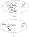
- the Fig. 1 schematically represents the deployment of femtocells in a macro-cellular network to illustrate the problem of co-channel interference between this network and these femtocells.
- Each femtocell FBSn uses the same channel as the macro-cellular network, that is to say the same carrier frequency f (co-channel deployment).
- Each femtocell FBSn can set its transmit power P t not which can vary in a power range extending from P min not at P max not .
- MUE Microcell User Equipment
- This MUE terminal can only connect to the macro-cellular network, that is to say that it does not belong to any of the CSG lists of the N femtocells.
- This terminal can only be attached to the base station MBS.
- FUEn terminal Femtocell User Equipment
- This terminal can be attached to either the femtocell FBSn or to the base station MBS.
- M terminals MUE also interfere with each other and with the N femtocells. We will note them later MUEm terminals.
- SINR Signal to Interference-plus-Noise Ratio
- the SINR is the ratio of the power received by the base station MBS over the sum of all the other powers received by the interfering base stations and the thermal noise.
- ⁇ MUE m P r MU E m
- macro is the power received by the terminal MUEm which is transmitted by the base station of the macro-cellular network to which this terminal is attached
- P r not is the power received by the terminal MUEm which is emitted by the femtocell FBSn
- ⁇ MU E m 2 is the sum of the power of the surrounding thermal noise and the power received by the MUEm terminal from the other base stations of the macro-cellular network (seen as white noise).
- the SINR ⁇ MUE m must be greater than or equal to a threshold value ⁇ MUE TARGET .
- ⁇ FUE not P r not ⁇ q ⁇ not P r q + P r FU E not , macro + ⁇ FU E not 2 or P r not is the power received by the terminal FUEn which is emitted by the femtocell FBSn
- P r q is the power received by the terminal FUEn which is emitted by the femtocell FBSq different from FBSn ( ⁇ 1 ⁇ q ⁇ N , q ⁇ n )
- P r FU E not macro is the power received by the terminal FUEn which is transmitted by the base station of the dominant macro-cellular network for this terminal (ie to which this terminal would be attached if it used the macro-cellular network)
- ⁇ FU E not 2 is the sum of the power of the surrounding thermal noise and the power received by the terminal F
- Such a method consists in minimizing the sum of the transmitting powers P t not 1 ⁇ not ⁇ NOT N femtocells under constraint of maintaining a minimum quality of service for both a terminal MUE and a terminal FUEn.
- Equation (3) is solved, in practice, either by a so-called centralized approach, that is to say by a central organ, or by a so-called distributed approach, that is to say that each femtocell optimizes its transmission power according to the power measurements it obtains locally.
- a signal of the type GPS Global Positioning System in English
- GPS Global Positioning System in English
- this optimization of the transmission powers requires that power measurements be carried out, in particular, by the MUEm terminals. This therefore requires the presence of at least one MUE terminal in the macro-cellular network to optimize these transmission powers in order to evaluate the constraints of equation (4).
- EP 2152041 A1 which describes a method for minimizing interference with mobile devices operating in a communication network that includes a centralized controller and a number of femtocells, wherein a power allocation priority order for each femtocell is determined, and wherein a power to be allocated to each base station managing such a femtocell is calculated based on the order of priority.
- the problem solved by the present invention is to overcome the drawbacks raised.
- the present invention relates to a method of reducing co-channel interference due to the deployment of N femtocells in a macro-cellular network, and a corresponding system, as presented in the appended claims.
- the system example of the Fig. 2 is given here for illustration purposes only.
- the system is formed by a set of N femtocells FBSn deployed under cover of a macro-cellular network here materialized by a base station MBS.
- a restricted access policy is implemented for femtocells as explained in the introductory part.
- the femtocells interfere with each other but also with the MBS base station because these N femtocells FBSn and the base station MBS use the same frequency transmission band (co-channel deployment).
- Each femtocell FBSn is intended to emit a signal at a particular transmit power P t not which can vary in a power range extending from P min not at P max not .
- each femtocell FBSn is intended to perform two types of power measurements, hereafter referred to as RSSI and RSRP.
- An RSSI ( Received Signal Strengh Indicator ) measurement is a measure of the power of a signal received by the femtocell FBSn. This signal can be the result of several signals emitted by one or more other femtocells and / or by one or more base stations of the macro-cellular network.
- a Reference Signal Received Power (RSRP) measurement is a measure of the strength of a signal that has been received by a femtocell and that has been emitted either by another particular femtocell or by a particular base station of the macro-cellular network.
- An RSRP measurement is performed, for example, on a channel where reference signals are always transmitted by a base station of the macro-cellular network or a femtocell.
- an RSRP measurement is defined for a mobile terminal ( CPICH RSCP, defined in 3GPP TS 25.215 V9.2.0 (2010-03), "Physical layer; Measurements (FDD) (Release 9) » , subclause 5.1.1 ) while in LTE this measurement is defined for a base station ( DL RS TX power , defined in 3GPP TS 36.214 V9.2.0 (2010-06), "Evolved Universal Terrestrial Radio Access; Physical layer; Measurements (FDD) (Release 9) » subclause 5.2.1).
- a femtocell FBSn When a femtocell FBSn performs RSSI or RSRP type measurements on its transmit band, it does not transmit at the same time, otherwise it would measure its own program whose level would be so high that it would dazzle it.
- the femtocells FBSn are connected to a central organ UC which may be, for example, a computer, a femtocell gateway ( femtocell-gateway in English), or a femtocell "master" to the extent that the latter can address the other femtocells of the network.
- the base stations can communicate directly with each other (ie without going through an organ of the core network of the mobile operator) through an interface called X2.
- the physical medium of the X2 interface is not explicitly defined, but only its logical functions. This interface can be used, for example, to exchange data for cooperation or to ensure continuity of service when a terminal moves and that it must change base station during communication ( hand- over in English).
- the femtocells can therefore be interconnected and / or connected to the central unit UC.
- the link between a femtocell FBSn and the central body UC which can be either wired or wireless, allows bidirectional communication of a signal Si whose frames are described in relation to the Figs. 5a and 5b .
- the central unit UC is provided to determine which femtocells are connected to the network and to determine the number N of femtocells whose transmission power must be optimized. Indeed, as each femtocell must register at each start, the UC central body is aware of the addition of any new femtocell and can thus regularly test if a femtocell is active. The central organ UC can then determine by this mechanism whether a femtocell is newly connected to the network or is no longer connected to the network.
- the present invention relates to a method for reducing co-channel interference due to the deployment of N femtocells in a macrocellular network.
- This method comprises a step 1 of taking measurements of the power of signals transmitted on this network, a step 3 of optimizing the transmission powers of the femtocells as a function of these measurements and a step 4 of assigning each femtocell its power. resignation.
- the power measurements are only taken by the femtocells and these measurements are ordered temporally by the central unit UC.
- the transmission powers of the N femtocells are maximized under the constraints of maintaining a minimum quality of service of the MUEm terminals that would be attached to the stations. basic macro-cellular network. These constraints are established through the measurements of step 1.
- the quality of service for FUEn terminals (which would be attached to the femtocells) is therefore not taken into account in the constraints as is done in the state of the art. This has little effect on the operation of a terminal FUEn which, if it does not have a good quality of service when attached to a femtocell FBSn, can be attached to a base station of macro-cellular network so that the quality of service that it perceives increases.
- a coefficient ⁇ is introduced in order to take into account the difference in position of the virtual terminal MUEm and the femtocell FBSn. This coefficient reflects the attenuation of the transmission power from the femtocell FBSn in the presence of a slight displacement of the measurement point (representing the virtual MUEm terminal).
- the worst case is considered, namely that if the virtual MUEm terminal moves away from the femtocell FBSn, it gets closer to all the other femtocells FBSm and the macro-cellular base station: the attenuation ⁇ associated with the power of the femtocell FBSn is then seen as a gain equal to 1 / ⁇ vis-à-vis other sources of power.
- This coefficient can be equal to one, which corresponds then to a virtual MUEm terminal positioning exactly at the level of the femtocell FBSn.
- the coefficient ⁇ reflects the coverage of a femtocell FBSn beyond which a MUEm terminal would see an SINR greater than ⁇ MUE TARGET .
- the distance of the position of the virtual terminal MUEm from the femtocell FBSn does not necessarily lead to a rimpedement towards the other femtocells FBSm and the base stations of the macro-cellular network (seen then as a gain), but can to drive away some femtocells FBSm or some base stations and thus be perceived by the virtual terminal MUEm as an attenuation of the power received from them.
- This variant makes it possible to prioritize the importance given to each of the femtocells to, for example, provide a higher quality of service to some of them.
- the transmission power of a femtocell is equal to the transmission power estimated during step 3 and can not exceed the extreme values of the range of power values. of this femtocell.
- a zero transmit power is assigned to a femtocell if its estimated transmission power in step 3 is zero.
- a zero transmit power is assigned to a femtocell if its estimated transmission power in step 3 is less than its minimum transmission power.
- the first embodiment of step 4 is recommended in the case of the use of a restricted access policy in which an independent CSG list is associated with each femtocell, while the second and third embodiments of Step 4 is recommended in the case of the use of a restricted access policy in which a CSG list common to femtocells is used.
- a transfer procedure ( hand -over in English) is initiated so that this terminal is attached either to another femtocell located nearby and to which it is allowed to be attached either to a base station of the macro-cellular network.
- this procedure is not successful, the femtocell should not change its transmit power.
- step 4 if a zero transmit power is allocated to a femtocell, this femtocell extinguishes its radio part but remains connected to the network in order to be taken into account during a new optimization of the powers of issue of the femtocells and that a non-zero emission power is attributed to it.
- the extinction of the radio part of the femtocells allows a random deployment of the latter in the macro-cellular network because as soon as a femtocell greatly disrupts the functioning of the macro-cellular network, this femtocell is extinguished and without human intervention. Moreover turning off the radio part of a femtocell from time to time brings a decrease in the consumption of the latter.
- the steps of the interference reduction method are performed periodically and / or when the traffic on these femtocells is low, for example at night and / or as soon as the central unit UC detects that a new femtocell is connected to the network or that a femtocell is no longer connected to the network.
- the Fig. 3 represents an illustration of a centralized implementation of the process.
- the measurement step 1 comprises a sub-step 11 of making measurements common to the femtocells and N successive sub-steps 12m of taking individual measurements.
- the central organ UC emits N requests A, each destined for one of the N femtocells.
- Each request A tells a femtocell FBSn to perform a RSRP type measurement of a particular base station and / or a RSSI type measurement.
- the femtocell FBSn emits no signal on the common transmit band.
- the measurement choice (RSSI and / or RSRP) is specified in each request A.
- femtocell FBSn obtains the received power from the macro-cellular network only, i.e. a measure of the received power of a signal that has been transmitted on the common transmit band by the base station of the macrocellular network considered dominant by femtocell FBSn P r not , macro .
- the femtocell FBSn obtains the sum of the received power of a signal that has been transmitted on the common transmission band by the base station of the macro-cellular network considered dominant by the femtocell FBSn P r not , macro and thermal noise surrounding the femtocell FBSn ⁇ not 2 .
- the central organ UC issues a request B to a femtocell FBSm.
- Query B tells the femtocell FBSm to send a signal to its maximum power P max m and the central organ UC sends a request A to each of the other ( N -1) femtocells to tell it to perform measurements.
- the central organ UC sends a request B to femtocell FSB1 instructing it to transmit a signal at its maximum power and a request A to each other femtocell FBSn to tell it not to transmit a signal on the transmission band and to carry out measurements.
- the central organ UC sends a request B to the femtocell FSB2 telling it to transmit a signal at its maximum power and a request A to each other femtocell FBSn to tell him not to emit signal on the emission band and perform measurements, etc.
- each femtocell FBSn performs during the sub-step 11 a measurement RSR P not 0 and during each sub-step 12m a measure RSR P not m (except at step 12n, where the femtocell FBSn must emit at full power).
- RSR P not 0 P r not , macro ⁇ m ⁇ not
- RSR P not m ⁇ not , m P max m
- each femtocell FBSn performs during the sub-step 11 a measurement RSR P not 0 and a measure RSS I not 0 and during each sub-step 12m a measure RSS I not m (except at step 12n, where the femtocell FBSn must emit at full power).
- This mode is advantageous because it is preferable to perform a RSRP measurement and N RSSI measurements rather than N RSRP measurements to decrease the total duration of the measurement while obtaining the same parameters used in the generation of constraints.
- an RSSI-type measure is carried out much faster than an RSRP measure.
- This mode is also advantageous because the appearance or disappearance of a femtocell in the network has little impact since RSSI measurements are taken to measure co-channel interference as a whole and not RSRP measures that would individually involve femtocell network.
- the number of measurements to be made by a femtocell FBSn is limited to a predefined VA value. In this case, only the measurements of the femtocells VA are considered, of which the powers received by the femtocell FBSn are the most important. Other measurements not received by femtocell FBSn are set to zero in the linear system.
- the step 1 of taking measurements is followed by a step 2 of collection of the measurements by the central unit UC.
- the central organ UC issues a request to each femtocell (referenced C1 on the Fig. 3 ) which sends in response the measures she has taken (referenced C2 on the Fig. 3 ).
- Step 2 is followed by step 3 of optimizing the emission powers of the femtocells as a function of the measurements collected.
- This step 3 is implemented by the central unit UC as shown in FIG. Fig. 3 by the rectangle that encompasses the arrow.
- the central unit UC calculates the attenuation coefficients ⁇ n , m from the measurements taken and using either the equation (10) or the equation (11) according to the embodiment used.
- the vector C is composed of only 1 if the system is formed from equation (6).
- the problem described by equation (12) is a linear optimization problem whose unknowns to find are positive (transmission powers).
- the central organ UC can then attempt to solve this linear system by using a resolution method, such as the simplex method, in order to estimate the N emission powers P ⁇ t not 1 ⁇ not ⁇ NOT .
- the central unit UC transmits to each femtocell FBSn a signal (referenced D on the Fig. 3 ) which carries the emission power P t not thus determined.
- a femtocell FBSn then emits at this new power level.
- the Fig. 4 represents an illustration of a distributed implementation of the method.
- the method is iterative, that is to say that steps 1, 3 and 4 are performed at each iteration i .
- the process stops either when a maximum number of iterations is reached or when the optimization of the transmit powers has converged towards a solution.
- One of the advantages of this implementation is that it does not require the transfer of the measurements taken by a femtocell because the optimization of the emitting power of a femtocell is calculated by this femtocell from the measurements that this femtocell took.
- Step 1 of taking measurements includes the substep 11 of taking measures common to femtocells which has been described in connection with the Fig.3 and N successive sub-steps of individual measurement 22n.
- the central organ UC sends a request (referenced A) to a femtocell FBSn to perform measurements (and therefore no longer transmit).
- a request A referenced A
- each femtocell FBSm ( m ⁇ n ) continues to function normally and transmits its reference channels / signals to the transmission power which has been assigned to it.
- the central organ UC sends a request A to the femtocell FSB1 telling it to perform measurements
- the central organ UC issues a request A to the femtocell FSB2 him indicating to carry out measurements, etc.
- each femtocell FBSn performs during the sub-step 11 a measurement RSR P not 0 and during substep 22n ( N -1) measurements RSR P not m .
- the femtocell FBSn continues to function normally.
- each femtocell FBSn performs during the sub-step 11 a measurement RSR P not 0 and a measure RSS I not 0 and during the sub-step 22n a measure RSS I not not .
- the femtocell FBSn continues to function normally.
- This mode is advantageous because it is preferable to perform two RSSI measurements and one RSRP measurement rather than N RSRP measurements to decrease the total duration of the measurement.
- an RSSI-type measure is carried out much faster than an RSRP measure.
- This mode is also advantageous because the appearance or disappearance of a femtocell in the network has little impact since RSSI measurements are taken to measure co-channel interference as a whole and not RSRP measures that would individually involve femtocell network.
- the request A of the step 22n for the femtocell FBSn also includes a counter (timer) at the end of which the femtocell FBSn will calculate its transmission power (step 3).
- Step 1 is thus followed by step 3 of optimizing the emission powers of the femtocells as a function of the measurements taken.
- This step 3 is implemented by each femtocell FBSn as illustrated in FIG. Fig. 4 by rectangles each including an arrow as soon as the counter associated with the request A and received in step 22n has reached a defined value.
- each femtocell FBSn updates its transmission power according to the following equation (19) deduced from equation (8) by considering that the constraints of the equation (7) are equalities.
- step 1 the first equality of equation (19) is used since all parameters are defined by equation (17).
- femtocell FBSn can either directly update its transmit power after performing the request of step 22n according to equation (20) or (21) (Gauss-Seidel case or SOR ), or wait for all the steps 22m ( m ⁇ n ) to be performed before updating its power according to equation (20) (Jacobi case). The presence of the counter in the request A allows this waiting.
- the central unit UC can also send a request for autonomous power update if no counter (timer) is included in the request A of the step 22n.
- the power value P t not i thus determined by this femtocell is used by this femtocell to emit signals (reference D on the Fig. 4 ).
- the central unit UC and each femtocell communicate with each other information carried by the signal Si.
- the central unit UC orders that measurements be made by the femtocells (request A) or that femtocell emits its maximum power (request B) and transmits the powers to be emitted by the femtocells (request D), and the femtocells transmit to the central organ UC the results of the measurements they have made and their ranges of power values ( response C2 following a request C1).
- These exchanges between the femtocells and the central organ UC are ordered temporally according to the method described in connection with the Fig. 3 and 4 whose implementation uses a protocol of communication using a logical interface based on a physical interface that can be wired or non-wired.
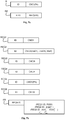
- the frame of the signal Si comprises, inter alia, an identifier ID and a command CMD when this signal is a request R issued by the central unit UC to a femtocell and information INFO when this signal is an answer RE of a femtocell to the central organ UC as shown in FIG. Fig. 5a .
- an answer RE is always relative to a previously sent request.
- This request is identified by an identifier which is here denoted R.ID to indicate that the information INFO of the response RE refers to a previous request R which has been received by a particular femtocell.
- the INFO information relates to several previous requests, each information relates to the identifier of the request to which this information corresponds.
- This identifier R.ID enables the central organ UC to discriminate the responses when the femtocell integrates this identifier R.ID in its response and that the central organ UC keeps track of its requests.
- the identifier ID of a request allows a femtocell to know what is the behavior that it must adopt following the reception of this request.
- the CMD command and the INFO information are accompanied or no PA parameter.
- the Fig. 5b illustrates embodiments of the Si signal frames that are used to construct the A, B, C1 and D requests and the C2 response and the described method in connection with the Figs. 3 and 4 .
- the request REQ1 includes a unique identifier and the command CMD1 which requests the femtocell receiving this request to perform a measurement of the RSSI type.
- the request REQ1 is equivalent to a request A.
- the request REQ2 includes a specific specific identifier and the command CMD2 which requests the femtocell receiving this request to perform a measurement of the RSRP type.
- This CMD2 command is associated with at least one parameter which indicates which of the MBS and / or femtocells base stations FBSn should carry this measurement.
- the REQ2 request is equivalent to a request A.
- the request REQ3 includes a unique identifier and the command CMD3 which requests the femtocell FBSn which receives this request to perform a measurement of the RSSI type and a RSRP-type measurement of the macro-cellular base station considered dominant by the femtocell FBSn.
- the REQ3 request is equivalent to a request A.
- the request REQ4 includes a unique identifier and the CMD4 command which requests the femtocell receiving this request to return all the measurement results obtained during previous CMD1, CMD2 or CMD3 command reception as well as its transmission power range.
- the measurement results once emitted, are erased from the femtocell.
- the femtocell receives a command CMD4 while it does not have results of measurements to emit, it emits nothing.
- the REQ4 request is equivalent to a C1 request.
- the request REQ5 includes a unique identifier and the command CMD5 which requests the femtocell receiving this request to transmit at a given power parameter.
- the request REQ5 is equivalent to a request D.
- the request REQ6 includes a unique identifier and the command CMD6 which asks the femtocell receiving this request to transmit at its maximum power.
- the REQ6 request is equivalent to a B request.
- the answer AN comprises the identifier REQ4.ID of the preceding request which triggered this answer AN, that is to say the identifier of the request at the origin of the generation of a frame which carries this answer, as well as the parameters corresponding to the information requested by this request (equivalent of a response C1).
- the INFO information comprises one or more REQ1.ID identifiers that enable the central unit UC to know which REQ1 requests are associated with the following RSSI type measurements, and / or one or more REQ2.ID identifiers that allow central unit UC to know which REQ2 requests are associated with the following RSRP type measurements, and / or one or more REQ3.ID identifiers which enable the central unit UC to know which REQ3 requests are associated with the type of measurements. RSSI and RSRP that follow, and the range of power values of femtocell FBSn.
- the association of the identifier of the request REQ1, REQ2 or REQ3 in the information INFO allows the femtocell not to have to send for each measurement the identity of the base station / femtocell target of the measurement, the central organ UC doing the correspondence through the identifiers.
- this communication protocol is done via protocol TR-069, a protocol defining the communications between a customer premise equipment (such as a femtocell) and an automatic configuration server.
- This protocol defined by the Broadband Forum in the technical report " TR-069 Amendment 3; CPE WAN Management Protocol ", Issue 1, November 2010 , allows generic remote management of equipment.
- the protocol TR-069 also allows the addition of specific parameters to a manufacturer ( Vendor Specific in English) then causing a specific behavior when received by the equipment and / or the automatic configuration server.
- Vendor Specific in English Vendor Specific in English
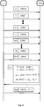
- the Fig. 6 represents an example of centralized implementation of the preferred embodiment of the method described in connection with the Fig. 3 when the signal Si uses frames described in relation to the Figs. 5a and 5b .
- the central body sends a REQ3 request to the femtocell FBSn which then carries out a measurement RSR P not 0 and a measure RSS I not 0 (step 11).
- the central organ UC emits ( N -1) requests REQ1 to the femtocell FBSn so that it realizes ( N -1) measurements RSS I not m (steps 12m).
- the central body sends at the same time a request REQ6 to the femtocell FBSm (not shown on the Fig. 6 ).
- the central organ UC also sends a REQ6 request to the femtocell FBSn so that the other femtocells FBSm can perform their measurements.
- RSS I m not (step 12n) in response to a REQ1 request (not shown on the Fig. 6 ).
- the central unit UC then sends a request REQ4 to ask the femtocell FBSn to send him the results of measurements it has made (step 2).
- the femtocell then emits an AN response that includes the measure RSR P not 0 , measurement RSS I not 0 and the ( N -1) measures RSS I not m that it has just achieved as well as its range of power values.
- the central unit UC then calculates, among other things, the transmission power of the femtocell FBSn (step 3) and sends a request REQ5 which indicates to the femtocell FBSn the power to which it must henceforth emit (step 4).
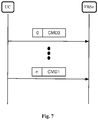
- the Fig. 7 represents an example of distributed implementation of the preferred embodiment of the method described in connection with the Fig. 4 when the signal Si uses frames described in relation to the Figs. 5a and 5b .
- the central organ UC sends a request REQ3 to the femtocell FBSn which then carries out a measurement RSR P not 0 and a measure RSS I not 0 (step 11).
- the central organ UC then sends a request REQ1 to the femtocell FBSn so that it carries out a measurement RSS I not not (step 22n).
- This query is associated with a counter (timer) that tells the femtocell FBSn when to calculate its new transmit power.
- the femtocell FBSn calculates its transmission power (step 3) and updates its power to which it will henceforth emit.
Landscapes
- Engineering & Computer Science (AREA)
- Computer Networks & Wireless Communication (AREA)
- Signal Processing (AREA)
- Quality & Reliability (AREA)
- Mobile Radio Communication Systems (AREA)
Claims (19)
- Verfahren zur Reduzierung der Gleichkanalinterferenzen aufgrund der Ausbreitung von N Femtozellen in einem makrozellularen Netz, wobei N eine ganze Zahl ist, wobei das Verfahren einen Schritt (1) der Durchführung von Leistungsmessungen von über dieses Netz gesendeten Signalen, während dessen die Leistungsmessungen nur von den N Femtozellen durchgeführt werden, und diese Messungen zeitlich von einem Zentralorgan UC des Systems geordnet werden, einen Schritt (3) der Optimierung der Sendeleistungen der Femtozellen abhängig von diesen Messungen, und einen Schritt (4) der Zuweisung ihrer Sendeleistung zu jeder Femtozelle aufweist,
wobei das Verfahren so ist, dass während des Optimierungsschritts (3) die Sendeleistungen der Femtozellen unter der Bedingung der Aufrechterhaltung einer minimalen Dienstqualität von Endgeräten maximiert werden, die an die Basisstationen des makrozellularen Netzes angeschlossen wären,
dadurch gekennzeichnet, dass das Verfahren so ist, dass während des Optimierungsschritts (3) die folgende Kostenfunktion maximiert wird:


- Verfahren nach Anspruch 1, wobei während des Zuteilungsschritts die geschätzte Sendeleistung einer Femtozelle während des Optimierungsschritts (3) auf die Endwerte eines Leistungswertebereichs dieser Femtozelle begrenzt ist.
- Verfahren nach Anspruch 1, wobei während des Zuteilungsschritts eine Sendeleistung Null einer Femtozelle zugeteilt wird, wenn ihre geschätzte Sendeleistung während des Optimierungsschritts (3) Null ist.
- Verfahren nach Anspruch 1, wobei während des Zuteilungsschritts eine Sendeleistung Null einer Femtozelle zugeteilt wird, wenn ihre geschätzte Sendeleistung niedriger als eine minimale Sendeleistung ist.
- Verfahren nach einem der Ansprüche 3 oder 4, wobei, wenn eine Sendeleistung Null einer Femtozelle zugeteilt wird, wenn ein Endgerät an diese Femtozelle angeschlossen ist und wenn das Endgerät gerade in Verbindung steht, eine Transferprozedur initiiert wird, damit dieses Endgerät sich entweder an eine andere Femtozelle, die sich in der Nähe befindet und an die es sich anschließen darf, oder an eine Basisstation des makrozellularen Netzes anschließt.
- Verfahren nach einem der Ansprüche 3 bis 5, wobei diese Femtozelle ihren Funkteil ausschaltet, aber mit dem Netz verbunden bleibt, um bei einer neuen Optimierung der Sendeleistungen der Femtozellen berücksichtigt werden zu können, und ihr eine Sendeleistung ungleich Null zugeteilt wird.
- Verfahren nach einem der vorhergehenden Ansprüche, wobei die Schritte des Verfahrens periodisch und/oder wenn der Verkehr auf diesen Femtozellen schwach ist und/oder sobald das zentrale Organ UC erfasst, dass eine neue Femtozelle mit dem Netz verbunden ist oder dass eine Femtozelle nicht mehr mit dem Netz verbunden ist, durchgeführt werden.
- Verfahren nach einem der Ansprüche 1 bis 7, wobei der Schritt (1) der Durchführung von Messungen einen Teilschritt (11) der Durchführung von den Femtozellen gemeinsamen Messungen und N aufeinanderfolgende Teilschritte (12m, 22n) der Durchführung einzelner Messungen aufweist.
- Verfahren nach Anspruch 8, das einen Schritt (2) des Sammelns der Messungen durch das zentrale Organ UC gefolgt vom Optimierungsschritt (3) aufweist, der von diesem zentralen Organ UC angewendet wird, gefolgt vom Schritt (4) der Zuteilung, während dessen das zentrale Organ UC zu jeder Femtozelle ein Signal sendet, das die Sendeleistung dieser Femtozelle trägt.
- Verfahren nach Anspruch 9, wobei während des Teilschritts (11) der Durchführung gemeinsamer Messungen keine Femtozelle ein Signal sendet und jede Femtozelle, FBSn genannt, eine Messung der Art RSRP von der empfangenen Leistung eines Signals, das von der Basisstation des makrozellularen Netzes gesendet wurde, die von der Femtozelle FBSn


- Verfahren nach Anspruch 10, wobei während des Teilschritts (11) der Durchführung gemeinsamer Messungen jede Femtozelle FBSn eine Messung der Art RSRP der empfangenen Leistung eines Signals durchführt, das von der Basisstation des makrozellularen Netzes gesendet wurde, die von dieser Femtozelle


- Verfahren nach Anspruch 10, wobei während des Teilschritts (11) der Durchführung gemeinsamer Messungen jede Femtozelle FBSn eine Messung der Art RSRP der empfangenen Leistung eines Signals, das von der Basisstation des makrozellularen Netzes gesendet wurde, die von dieser Femtozelle


- Verfahren nach Anspruch 8, wobei der Schritt (1) der Durchführung von Messungen, der Optimierungsschritt (3), der von jeder Femtozelle ausgeführt wird, der Zuteilungsschritt (4), während dessen jede Femtozelle ihre aktuelle Sendeleistung durch die so optimierte Sendeleistung ersetzt, wiederholt werden.
- Verfahren nach Anspruch 13, wobei während des Teilschritts (11) der Durchführung gemeinsamer Messungen keine Femtozelle ein Signal sendet, und jede Femtozelle, FBSn genannt, eine Messung der Art RSRP der empfangenen Leistung eines Signals, das von der Basisstation des makrozellularen Netzes gesendet wurde, die von der Femtozelle FBSn


- Verfahren nach Anspruch 14, wobei während des Teilschritts (11) der Durchführung gemeinsamer Messungen jede Femtozelle FBSn eine Messung der Art RSRP der empfangenen Leistung eines Signals ausführt, das von der Basisstation des makrozellularen Netzes gesendet wurde, die von dieser Femtozelle


- Verfahren nach Anspruch 14, wobei während des Teilschritts (11) der Durchführung gemeinsamer Messungen jede Femtozelle FBSn eine Messung der Art RSRP der empfangenen Leistung eines Signals, das von der Basisstation des makrozellularen Netzes gesendet wurde, die von dieser Femtozelle


- System zur Reduzierung der Gleichkanalinterferenzen aufgrund der Ausbreitung von N Femtozellen in einem makrozellularen Netz, wobei N eine ganze Zahl ist, wobei das System Einrichtungen zur Durchführung von Leistungsmessungen von auf diesem Netz gesendeten Signalen, so dass die Leistungsmessungen nur von den N Femtozellen durchgeführt werden, und diese Messungen zeitlich von einem Zentralorgan UC des Systems geordnet werden, Einrichtungen zur Optimierung der Sendeleistungen der Femtozellen abhängig von diesen Messungen, und Einrichtungen zur Zuteilung ihrer Sendeleistung zu jeder Femtozelle aufweist,
wobei das System geeignet ist, damit während der Optimierung durch die Optimierungseinrichtungen die Sendeleistungen der Femtozellen unter der Bedingung einer Aufrechterhaltung einer minimalen Dienstqualität von Endgeräten maximiert werden, die an die Basisstationen des makrozellularen Netzes angeschlossen wären,
dadurch gekennzeichnet, dass das System geeignet ist, damit während der Optimierung die folgende Kostenfunktion maximiert wird:


- System nach Anspruch 17, wobei jede Femtozelle ebenfalls vorgesehen ist, um ihre Sendeleistung gemäß Messungen zu optimieren, die sie durchgeführt hat.
- System nach Anspruch 17, wobei das zentrale Organ UC ebenfalls Einrichtungen aufweist, um die von den Femtozellen durchgeführten Messungen zu sammeln, um ihre Sendeleistung zu optimieren und um ihre so optimierte Sendeleistung an diese Femtozellen zu senden.
Applications Claiming Priority (2)
| Application Number | Priority Date | Filing Date | Title |
|---|---|---|---|
| FR1154322A FR2975562B1 (fr) | 2011-05-18 | 2011-05-18 | Procede et systeme de reduction des interferences co-canal dues au deploiement de femtocells dans un reseau macro-cellulaire |
| PCT/EP2012/056755 WO2012156158A2 (fr) | 2011-05-18 | 2012-04-13 | Procédé et système de réduction des interférences co-canal dues au déploiement de femtocells dans un réseau macro-cellulaire |
Publications (2)
| Publication Number | Publication Date |
|---|---|
| EP2710831A2 EP2710831A2 (de) | 2014-03-26 |
| EP2710831B1 true EP2710831B1 (de) | 2018-02-28 |
Family
ID=45999815
Family Applications (1)
| Application Number | Title | Priority Date | Filing Date |
|---|---|---|---|
| EP12716340.0A Active EP2710831B1 (de) | 2011-05-18 | 2012-04-13 | Verfahren und system zur verringerung der gleichkanalinterferenz aufgrund des einsatzes von femtozellen in einem makrozellularen netzwerk |
Country Status (4)
| Country | Link |
|---|---|
| US (1) | US9622193B2 (de) |
| EP (1) | EP2710831B1 (de) |
| FR (1) | FR2975562B1 (de) |
| WO (1) | WO2012156158A2 (de) |
Families Citing this family (3)
| Publication number | Priority date | Publication date | Assignee | Title |
|---|---|---|---|---|
| CN105704733B (zh) * | 2014-11-24 | 2019-05-17 | 联想(北京)有限公司 | 信息处理方法及电子设备 |
| KR102146266B1 (ko) * | 2019-05-28 | 2020-08-21 | 한국외국어대학교 연구산학협력단 | 무선 통신 시스템의 전력 제어 방법 및 장치 |
| CN111065121B (zh) * | 2019-12-27 | 2022-04-08 | 烟台大学 | 一种考虑小区差异的密集网络能耗及能效联合优化方法 |
Family Cites Families (7)
| Publication number | Priority date | Publication date | Assignee | Title |
|---|---|---|---|---|
| US8909279B2 (en) * | 2007-08-10 | 2014-12-09 | Qualcomm Incorporated | Adaptation of transmit power for neighboring nodes |
| CN102124696A (zh) * | 2008-06-18 | 2011-07-13 | 蜘蛛云无线股份有限公司 | 基于监控结果协调网络监控和/或自动操作装置配置的方法和设备 |
| US8285322B2 (en) * | 2008-08-08 | 2012-10-09 | Motorola Mobility Llc | Minimizing inter-femtocell downlink interference |
| US8938238B2 (en) * | 2009-11-06 | 2015-01-20 | Qualcomm Incorporated | Restricting access point transmissions |
| US8824383B2 (en) * | 2010-06-22 | 2014-09-02 | Telefonaktiebolaget L M Ericsson (Publ) | Downlink scheduling in heterogeneous networks |
| US20120238279A1 (en) * | 2010-09-28 | 2012-09-20 | Qualcomm Incorporated | Transmission power coordination for small-coverage base stations |
| US20120113961A1 (en) * | 2010-11-08 | 2012-05-10 | Motorola Mobility, Inc. | Interference Measurements in Enhanced Inter-Cell Interference Coordination Capable Wireless Terminals |
-
2011
- 2011-05-18 FR FR1154322A patent/FR2975562B1/fr not_active Expired - Fee Related
-
2012
- 2012-04-13 US US14/117,413 patent/US9622193B2/en active Active
- 2012-04-13 WO PCT/EP2012/056755 patent/WO2012156158A2/fr not_active Ceased
- 2012-04-13 EP EP12716340.0A patent/EP2710831B1/de active Active
Also Published As
| Publication number | Publication date |
|---|---|
| FR2975562A1 (fr) | 2012-11-23 |
| EP2710831A2 (de) | 2014-03-26 |
| US9622193B2 (en) | 2017-04-11 |
| WO2012156158A4 (fr) | 2013-04-25 |
| FR2975562B1 (fr) | 2016-08-05 |
| WO2012156158A3 (fr) | 2013-03-07 |
| US20140335849A1 (en) | 2014-11-13 |
| WO2012156158A2 (fr) | 2012-11-22 |
Similar Documents
| Publication | Publication Date | Title |
|---|---|---|
| Fourati et al. | A survey of 5G network systems: challenges and machine learning approaches | |
| US8660556B2 (en) | Femtocell use for radio frequency network sweeps | |
| US20240223292A1 (en) | Interference detection and avoidance in citizen broadband radio service (cbrs) | |
| US20150302123A1 (en) | X-maps with flexible tiles | |
| US20150049681A1 (en) | Small cell deployment scheduling | |
| US20130344882A1 (en) | Femto parameter profiles based upon nearby access point | |
| US8825064B2 (en) | Femtocell measurements for merger integration planning | |
| WO2000001181A1 (fr) | Procede et dispositif de selection de parametres dans un reseau cellulaire de radiocommunication | |
| US20250392985A1 (en) | Energy efficient for massive and extreme massive multiple-input multiple-output (mmimo) systems | |
| EP2710831B1 (de) | Verfahren und system zur verringerung der gleichkanalinterferenz aufgrund des einsatzes von femtozellen in einem makrozellularen netzwerk | |
| Fortes et al. | Location-based distributed sleeping cell detection and root cause analysis for 5G ultra-dense networks | |
| FR3059197A1 (fr) | Procede d'allocation de ressources dans un reseau d'acces, station de base, produit programme d'ordinateur et support d'information correspondants | |
| FR2977117A1 (fr) | Procede de controle de puissance dans les reseaux mobiles | |
| FR3055081A1 (fr) | Procede de controle de position d'un noeud mobile et dispositif associe | |
| FR2768289A1 (fr) | Procede de transfert de communication entre deux cellules d'un reseau de radio-communication cellulaire numerique | |
| FR3058864B1 (fr) | Procede de determination d'une configuration de relais entre un point d'acces et des terminaux dans une architecture reseau | |
| EP2875687A1 (de) | Verfahren zum verwalten der konfiguration eines telekommunikationsnetzwerks | |
| US12526122B2 (en) | Flexible configuration of indoor radios to facilitate coexistence with outdoor radios | |
| EP3039921B1 (de) | Verfahren zum definieren von parameterwerten zur sendeleistungsregelung eines teils einer benutzervorrichtung | |
| WO2009101349A1 (fr) | Procede de determination de niveau de bruit en voie montante dans un reseau de communication, et dispositifs correspondants | |
| Iacoboaiea | Coordination of Self-Organizing Network (SON) functions in next generation radio access networks | |
| EP3545711A1 (de) | Auswahl einer telekommunikationsinfrastruktur | |
| Youssef | New approaches for resource allocation in future communication networks using NOMA and UAVs | |
| FR3058860B1 (fr) | Procede de gestion du transfert cellulaire d'informations et architecture de reseau | |
| FR3146566A1 (fr) | Procédé et dispositif de diagnostic pour un réseau local sans fil |
Legal Events
| Date | Code | Title | Description |
|---|---|---|---|
| PUAI | Public reference made under article 153(3) epc to a published international application that has entered the european phase |
Free format text: ORIGINAL CODE: 0009012 |
|
| 17P | Request for examination filed |
Effective date: 20131213 |
|
| AK | Designated contracting states |
Kind code of ref document: A2 Designated state(s): AL AT BE BG CH CY CZ DE DK EE ES FI FR GB GR HR HU IE IS IT LI LT LU LV MC MK MT NL NO PL PT RO RS SE SI SK SM TR |
|
| DAX | Request for extension of the european patent (deleted) | ||
| RAP1 | Party data changed (applicant data changed or rights of an application transferred) |
Owner name: SAGEMCOM SAS |
|
| RAP1 | Party data changed (applicant data changed or rights of an application transferred) |
Owner name: SAGEMCOM BROADBAND SAS |
|
| 17Q | First examination report despatched |
Effective date: 20170206 |
|
| GRAP | Despatch of communication of intention to grant a patent |
Free format text: ORIGINAL CODE: EPIDOSNIGR1 |
|
| INTG | Intention to grant announced |
Effective date: 20170922 |
|
| GRAS | Grant fee paid |
Free format text: ORIGINAL CODE: EPIDOSNIGR3 |
|
| GRAA | (expected) grant |
Free format text: ORIGINAL CODE: 0009210 |
|
| AK | Designated contracting states |
Kind code of ref document: B1 Designated state(s): AL AT BE BG CH CY CZ DE DK EE ES FI FR GB GR HR HU IE IS IT LI LT LU LV MC MK MT NL NO PL PT RO RS SE SI SK SM TR |
|
| REG | Reference to a national code |
Ref country code: GB Ref legal event code: FG4D Free format text: NOT ENGLISH Ref country code: CH Ref legal event code: EP |
|
| REG | Reference to a national code |
Ref country code: AT Ref legal event code: REF Ref document number: 975416 Country of ref document: AT Kind code of ref document: T Effective date: 20180315 |
|
| REG | Reference to a national code |
Ref country code: IE Ref legal event code: FG4D Free format text: LANGUAGE OF EP DOCUMENT: FRENCH |
|
| REG | Reference to a national code |
Ref country code: FR Ref legal event code: PLFP Year of fee payment: 7 |
|
| REG | Reference to a national code |
Ref country code: DE Ref legal event code: R096 Ref document number: 602012043334 Country of ref document: DE |
|
| REG | Reference to a national code |
Ref country code: NL Ref legal event code: MP Effective date: 20180228 |
|
| REG | Reference to a national code |
Ref country code: LT Ref legal event code: MG4D |
|
| REG | Reference to a national code |
Ref country code: AT Ref legal event code: MK05 Ref document number: 975416 Country of ref document: AT Kind code of ref document: T Effective date: 20180228 |
|
| PG25 | Lapsed in a contracting state [announced via postgrant information from national office to epo] |
Ref country code: ES Free format text: LAPSE BECAUSE OF FAILURE TO SUBMIT A TRANSLATION OF THE DESCRIPTION OR TO PAY THE FEE WITHIN THE PRESCRIBED TIME-LIMIT Effective date: 20180228 Ref country code: LT Free format text: LAPSE BECAUSE OF FAILURE TO SUBMIT A TRANSLATION OF THE DESCRIPTION OR TO PAY THE FEE WITHIN THE PRESCRIBED TIME-LIMIT Effective date: 20180228 Ref country code: CY Free format text: LAPSE BECAUSE OF FAILURE TO SUBMIT A TRANSLATION OF THE DESCRIPTION OR TO PAY THE FEE WITHIN THE PRESCRIBED TIME-LIMIT Effective date: 20180228 Ref country code: NL Free format text: LAPSE BECAUSE OF FAILURE TO SUBMIT A TRANSLATION OF THE DESCRIPTION OR TO PAY THE FEE WITHIN THE PRESCRIBED TIME-LIMIT Effective date: 20180228 Ref country code: FI Free format text: LAPSE BECAUSE OF FAILURE TO SUBMIT A TRANSLATION OF THE DESCRIPTION OR TO PAY THE FEE WITHIN THE PRESCRIBED TIME-LIMIT Effective date: 20180228 Ref country code: HR Free format text: LAPSE BECAUSE OF FAILURE TO SUBMIT A TRANSLATION OF THE DESCRIPTION OR TO PAY THE FEE WITHIN THE PRESCRIBED TIME-LIMIT Effective date: 20180228 Ref country code: NO Free format text: LAPSE BECAUSE OF FAILURE TO SUBMIT A TRANSLATION OF THE DESCRIPTION OR TO PAY THE FEE WITHIN THE PRESCRIBED TIME-LIMIT Effective date: 20180528 |
|
| PG25 | Lapsed in a contracting state [announced via postgrant information from national office to epo] |
Ref country code: AT Free format text: LAPSE BECAUSE OF FAILURE TO SUBMIT A TRANSLATION OF THE DESCRIPTION OR TO PAY THE FEE WITHIN THE PRESCRIBED TIME-LIMIT Effective date: 20180228 Ref country code: GR Free format text: LAPSE BECAUSE OF FAILURE TO SUBMIT A TRANSLATION OF THE DESCRIPTION OR TO PAY THE FEE WITHIN THE PRESCRIBED TIME-LIMIT Effective date: 20180529 Ref country code: BG Free format text: LAPSE BECAUSE OF FAILURE TO SUBMIT A TRANSLATION OF THE DESCRIPTION OR TO PAY THE FEE WITHIN THE PRESCRIBED TIME-LIMIT Effective date: 20180528 Ref country code: RS Free format text: LAPSE BECAUSE OF FAILURE TO SUBMIT A TRANSLATION OF THE DESCRIPTION OR TO PAY THE FEE WITHIN THE PRESCRIBED TIME-LIMIT Effective date: 20180228 Ref country code: LV Free format text: LAPSE BECAUSE OF FAILURE TO SUBMIT A TRANSLATION OF THE DESCRIPTION OR TO PAY THE FEE WITHIN THE PRESCRIBED TIME-LIMIT Effective date: 20180228 Ref country code: SE Free format text: LAPSE BECAUSE OF FAILURE TO SUBMIT A TRANSLATION OF THE DESCRIPTION OR TO PAY THE FEE WITHIN THE PRESCRIBED TIME-LIMIT Effective date: 20180228 |
|
| PG25 | Lapsed in a contracting state [announced via postgrant information from national office to epo] |
Ref country code: MT Free format text: LAPSE BECAUSE OF FAILURE TO SUBMIT A TRANSLATION OF THE DESCRIPTION OR TO PAY THE FEE WITHIN THE PRESCRIBED TIME-LIMIT Effective date: 20180228 |
|
| PG25 | Lapsed in a contracting state [announced via postgrant information from national office to epo] |
Ref country code: RO Free format text: LAPSE BECAUSE OF FAILURE TO SUBMIT A TRANSLATION OF THE DESCRIPTION OR TO PAY THE FEE WITHIN THE PRESCRIBED TIME-LIMIT Effective date: 20180228 Ref country code: AL Free format text: LAPSE BECAUSE OF FAILURE TO SUBMIT A TRANSLATION OF THE DESCRIPTION OR TO PAY THE FEE WITHIN THE PRESCRIBED TIME-LIMIT Effective date: 20180228 Ref country code: PL Free format text: LAPSE BECAUSE OF FAILURE TO SUBMIT A TRANSLATION OF THE DESCRIPTION OR TO PAY THE FEE WITHIN THE PRESCRIBED TIME-LIMIT Effective date: 20180228 Ref country code: EE Free format text: LAPSE BECAUSE OF FAILURE TO SUBMIT A TRANSLATION OF THE DESCRIPTION OR TO PAY THE FEE WITHIN THE PRESCRIBED TIME-LIMIT Effective date: 20180228 Ref country code: IT Free format text: LAPSE BECAUSE OF FAILURE TO SUBMIT A TRANSLATION OF THE DESCRIPTION OR TO PAY THE FEE WITHIN THE PRESCRIBED TIME-LIMIT Effective date: 20180228 |
|
| REG | Reference to a national code |
Ref country code: DE Ref legal event code: R097 Ref document number: 602012043334 Country of ref document: DE |
|
| PG25 | Lapsed in a contracting state [announced via postgrant information from national office to epo] |
Ref country code: DK Free format text: LAPSE BECAUSE OF FAILURE TO SUBMIT A TRANSLATION OF THE DESCRIPTION OR TO PAY THE FEE WITHIN THE PRESCRIBED TIME-LIMIT Effective date: 20180228 Ref country code: SM Free format text: LAPSE BECAUSE OF FAILURE TO SUBMIT A TRANSLATION OF THE DESCRIPTION OR TO PAY THE FEE WITHIN THE PRESCRIBED TIME-LIMIT Effective date: 20180228 Ref country code: CZ Free format text: LAPSE BECAUSE OF FAILURE TO SUBMIT A TRANSLATION OF THE DESCRIPTION OR TO PAY THE FEE WITHIN THE PRESCRIBED TIME-LIMIT Effective date: 20180228 Ref country code: SK Free format text: LAPSE BECAUSE OF FAILURE TO SUBMIT A TRANSLATION OF THE DESCRIPTION OR TO PAY THE FEE WITHIN THE PRESCRIBED TIME-LIMIT Effective date: 20180228 Ref country code: MC Free format text: LAPSE BECAUSE OF FAILURE TO SUBMIT A TRANSLATION OF THE DESCRIPTION OR TO PAY THE FEE WITHIN THE PRESCRIBED TIME-LIMIT Effective date: 20180228 |
|
| REG | Reference to a national code |
Ref country code: CH Ref legal event code: PL |
|
| REG | Reference to a national code |
Ref country code: BE Ref legal event code: MM Effective date: 20180430 |
|
| PLBE | No opposition filed within time limit |
Free format text: ORIGINAL CODE: 0009261 |
|
| STAA | Information on the status of an ep patent application or granted ep patent |
Free format text: STATUS: NO OPPOSITION FILED WITHIN TIME LIMIT |
|
| REG | Reference to a national code |
Ref country code: IE Ref legal event code: MM4A |
|
| PG25 | Lapsed in a contracting state [announced via postgrant information from national office to epo] |
Ref country code: LU Free format text: LAPSE BECAUSE OF NON-PAYMENT OF DUE FEES Effective date: 20180413 |
|
| 26N | No opposition filed |
Effective date: 20181129 |
|
| PG25 | Lapsed in a contracting state [announced via postgrant information from national office to epo] |
Ref country code: BE Free format text: LAPSE BECAUSE OF NON-PAYMENT OF DUE FEES Effective date: 20180430 Ref country code: LI Free format text: LAPSE BECAUSE OF NON-PAYMENT OF DUE FEES Effective date: 20180430 Ref country code: SI Free format text: LAPSE BECAUSE OF FAILURE TO SUBMIT A TRANSLATION OF THE DESCRIPTION OR TO PAY THE FEE WITHIN THE PRESCRIBED TIME-LIMIT Effective date: 20180228 Ref country code: CH Free format text: LAPSE BECAUSE OF NON-PAYMENT OF DUE FEES Effective date: 20180430 |
|
| PG25 | Lapsed in a contracting state [announced via postgrant information from national office to epo] |
Ref country code: IE Free format text: LAPSE BECAUSE OF NON-PAYMENT OF DUE FEES Effective date: 20180413 |
|
| PG25 | Lapsed in a contracting state [announced via postgrant information from national office to epo] |
Ref country code: TR Free format text: LAPSE BECAUSE OF FAILURE TO SUBMIT A TRANSLATION OF THE DESCRIPTION OR TO PAY THE FEE WITHIN THE PRESCRIBED TIME-LIMIT Effective date: 20180228 |
|
| PG25 | Lapsed in a contracting state [announced via postgrant information from national office to epo] |
Ref country code: PT Free format text: LAPSE BECAUSE OF FAILURE TO SUBMIT A TRANSLATION OF THE DESCRIPTION OR TO PAY THE FEE WITHIN THE PRESCRIBED TIME-LIMIT Effective date: 20180228 Ref country code: HU Free format text: LAPSE BECAUSE OF FAILURE TO SUBMIT A TRANSLATION OF THE DESCRIPTION OR TO PAY THE FEE WITHIN THE PRESCRIBED TIME-LIMIT; INVALID AB INITIO Effective date: 20120413 |
|
| PG25 | Lapsed in a contracting state [announced via postgrant information from national office to epo] |
Ref country code: MK Free format text: LAPSE BECAUSE OF NON-PAYMENT OF DUE FEES Effective date: 20180228 |
|
| PG25 | Lapsed in a contracting state [announced via postgrant information from national office to epo] |
Ref country code: IS Free format text: LAPSE BECAUSE OF FAILURE TO SUBMIT A TRANSLATION OF THE DESCRIPTION OR TO PAY THE FEE WITHIN THE PRESCRIBED TIME-LIMIT Effective date: 20180628 |
|
| REG | Reference to a national code |
Ref country code: DE Ref legal event code: R082 Ref document number: 602012043334 Country of ref document: DE Representative=s name: PUSCHMANN BORCHERT KAISER KLETTNER PATENTANWAE, DE Ref country code: DE Ref legal event code: R082 Ref document number: 602012043334 Country of ref document: DE Representative=s name: PATCARE PATENTANWAELTE PARTNERSCHAFT MBB, DE |
|
| PGFP | Annual fee paid to national office [announced via postgrant information from national office to epo] |
Ref country code: DE Payment date: 20250319 Year of fee payment: 14 |
|
| PGFP | Annual fee paid to national office [announced via postgrant information from national office to epo] |
Ref country code: GB Payment date: 20260319 Year of fee payment: 15 |
|
| PGFP | Annual fee paid to national office [announced via postgrant information from national office to epo] |
Ref country code: FR Payment date: 20260320 Year of fee payment: 15 |