EP2711076A2 - Appareil de traitement de fluide - Google Patents
Appareil de traitement de fluide Download PDFInfo
- Publication number
- EP2711076A2 EP2711076A2 EP13185455.6A EP13185455A EP2711076A2 EP 2711076 A2 EP2711076 A2 EP 2711076A2 EP 13185455 A EP13185455 A EP 13185455A EP 2711076 A2 EP2711076 A2 EP 2711076A2
- Authority
- EP
- European Patent Office
- Prior art keywords
- primary product
- lumen
- product collection
- stream
- assembly
- Prior art date
- Legal status (The legal status is an assumption and is not a legal conclusion. Google has not performed a legal analysis and makes no representation as to the accuracy of the status listed.)
- Withdrawn
Links
- 239000012530 fluid Substances 0.000 title claims abstract description 175
- 238000004891 communication Methods 0.000 claims abstract description 70
- 238000000034 method Methods 0.000 claims description 54
- 230000001678 irradiating effect Effects 0.000 claims description 29
- 238000011144 upstream manufacturing Methods 0.000 claims description 19
- 239000000463 material Substances 0.000 claims description 11
- 239000000047 product Substances 0.000 description 482
- 239000007789 gas Substances 0.000 description 118
- 239000002904 solvent Substances 0.000 description 21
- 238000006243 chemical reaction Methods 0.000 description 14
- 238000010586 diagram Methods 0.000 description 13
- 238000004458 analytical method Methods 0.000 description 12
- 239000007788 liquid Substances 0.000 description 12
- 238000002955 isolation Methods 0.000 description 11
- 239000000376 reactant Substances 0.000 description 11
- 238000002347 injection Methods 0.000 description 9
- 239000007924 injection Substances 0.000 description 9
- 230000001276 controlling effect Effects 0.000 description 6
- 239000011521 glass Substances 0.000 description 3
- 239000011261 inert gas Substances 0.000 description 3
- 230000001105 regulatory effect Effects 0.000 description 3
- 239000000126 substance Substances 0.000 description 3
- XKRFYHLGVUSROY-UHFFFAOYSA-N Argon Chemical compound [Ar] XKRFYHLGVUSROY-UHFFFAOYSA-N 0.000 description 2
- IJGRMHOSHXDMSA-UHFFFAOYSA-N Atomic nitrogen Chemical compound N#N IJGRMHOSHXDMSA-UHFFFAOYSA-N 0.000 description 2
- 238000000065 atmospheric pressure chemical ionisation Methods 0.000 description 2
- 238000000451 chemical ionisation Methods 0.000 description 2
- 238000004140 cleaning Methods 0.000 description 2
- 238000000132 electrospray ionisation Methods 0.000 description 2
- 238000010438 heat treatment Methods 0.000 description 2
- 239000012263 liquid product Substances 0.000 description 2
- 238000004519 manufacturing process Methods 0.000 description 2
- 230000005855 radiation Effects 0.000 description 2
- 239000002699 waste material Substances 0.000 description 2
- OKTJSMMVPCPJKN-UHFFFAOYSA-N Carbon Chemical compound [C] OKTJSMMVPCPJKN-UHFFFAOYSA-N 0.000 description 1
- 239000011358 absorbing material Substances 0.000 description 1
- PNEYBMLMFCGWSK-UHFFFAOYSA-N aluminium oxide Inorganic materials [O-2].[O-2].[O-2].[Al+3].[Al+3] PNEYBMLMFCGWSK-UHFFFAOYSA-N 0.000 description 1
- 229910052786 argon Inorganic materials 0.000 description 1
- 238000013473 artificial intelligence Methods 0.000 description 1
- 230000004888 barrier function Effects 0.000 description 1
- -1 catalysis Substances 0.000 description 1
- 238000007084 catalytic combustion reaction Methods 0.000 description 1
- 238000006555 catalytic reaction Methods 0.000 description 1
- 239000003610 charcoal Substances 0.000 description 1
- 239000003153 chemical reaction reagent Substances 0.000 description 1
- 238000004587 chromatography analysis Methods 0.000 description 1
- 239000012141 concentrate Substances 0.000 description 1
- 238000010276 construction Methods 0.000 description 1
- 238000009795 derivation Methods 0.000 description 1
- 238000010790 dilution Methods 0.000 description 1
- 239000012895 dilution Substances 0.000 description 1
- 238000005516 engineering process Methods 0.000 description 1
- 229910002804 graphite Inorganic materials 0.000 description 1
- 239000010439 graphite Substances 0.000 description 1
- 230000001939 inductive effect Effects 0.000 description 1
- 150000002500 ions Chemical class 0.000 description 1
- 239000007791 liquid phase Substances 0.000 description 1
- 239000002184 metal Substances 0.000 description 1
- 239000007769 metal material Substances 0.000 description 1
- 238000004853 microextraction Methods 0.000 description 1
- 238000002156 mixing Methods 0.000 description 1
- 229910052757 nitrogen Inorganic materials 0.000 description 1
- 238000009928 pasteurization Methods 0.000 description 1
- 239000012071 phase Substances 0.000 description 1
- 230000002028 premature Effects 0.000 description 1
- 230000001681 protective effect Effects 0.000 description 1
- 238000010926 purge Methods 0.000 description 1
- 238000004064 recycling Methods 0.000 description 1
- HBMJWWWQQXIZIP-UHFFFAOYSA-N silicon carbide Chemical compound [Si+]#[C-] HBMJWWWQQXIZIP-UHFFFAOYSA-N 0.000 description 1
- 229910010271 silicon carbide Inorganic materials 0.000 description 1
- 239000000243 solution Substances 0.000 description 1
- 230000001954 sterilising effect Effects 0.000 description 1
- 238000004659 sterilization and disinfection Methods 0.000 description 1
- 239000012780 transparent material Substances 0.000 description 1
- 238000002604 ultrasonography Methods 0.000 description 1
Images





Classifications
-
- B—PERFORMING OPERATIONS; TRANSPORTING
- B01—PHYSICAL OR CHEMICAL PROCESSES OR APPARATUS IN GENERAL
- B01J—CHEMICAL OR PHYSICAL PROCESSES, e.g. CATALYSIS OR COLLOID CHEMISTRY; THEIR RELEVANT APPARATUS
- B01J19/00—Chemical, physical or physico-chemical processes in general; Their relevant apparatus
- B01J19/08—Processes employing the direct application of electric or wave energy, or particle radiation; Apparatus therefor
- B01J19/12—Processes employing the direct application of electric or wave energy, or particle radiation; Apparatus therefor employing electromagnetic waves
- B01J19/122—Incoherent waves
- B01J19/126—Microwaves
-
- A—HUMAN NECESSITIES
- A23—FOODS OR FOODSTUFFS; TREATMENT THEREOF, NOT COVERED BY OTHER CLASSES
- A23B—PRESERVATION OF FOODS, FOODSTUFFS OR NON-ALCOHOLIC BEVERAGES; CHEMICAL RIPENING OF FRUIT OR VEGETABLES
- A23B2/00—Preservation of foods or foodstuffs, in general
- A23B2/05—Preservation of foods or foodstuffs, in general by heating using irradiation or electric treatment
- A23B2/08—Preservation of foods or foodstuffs, in general by heating using irradiation or electric treatment using microwaves or dielectric heating
-
- B—PERFORMING OPERATIONS; TRANSPORTING
- B01—PHYSICAL OR CHEMICAL PROCESSES OR APPARATUS IN GENERAL
- B01J—CHEMICAL OR PHYSICAL PROCESSES, e.g. CATALYSIS OR COLLOID CHEMISTRY; THEIR RELEVANT APPARATUS
- B01J19/00—Chemical, physical or physico-chemical processes in general; Their relevant apparatus
- B01J19/0093—Microreactors, e.g. miniaturised or microfabricated reactors
-
- G—PHYSICS
- G01—MEASURING; TESTING
- G01N—INVESTIGATING OR ANALYSING MATERIALS BY DETERMINING THEIR CHEMICAL OR PHYSICAL PROPERTIES
- G01N1/00—Sampling; Preparing specimens for investigation
- G01N1/28—Preparing specimens for investigation including physical details of (bio-)chemical methods covered elsewhere, e.g. G01N33/50, C12Q
- G01N1/44—Sample treatment involving radiation, e.g. heat
-
- G—PHYSICS
- G01—MEASURING; TESTING
- G01N—INVESTIGATING OR ANALYSING MATERIALS BY DETERMINING THEIR CHEMICAL OR PHYSICAL PROPERTIES
- G01N35/00—Automatic analysis not limited to methods or materials provided for in any single one of groups G01N1/00 - G01N33/00; Handling materials therefor
- G01N35/10—Devices for transferring samples or any liquids to, in, or from, the analysis apparatus, e.g. suction devices, injection devices
- G01N35/1095—Devices for transferring samples or any liquids to, in, or from, the analysis apparatus, e.g. suction devices, injection devices for supplying the samples to flow-through analysers
- G01N35/1097—Devices for transferring samples or any liquids to, in, or from, the analysis apparatus, e.g. suction devices, injection devices for supplying the samples to flow-through analysers characterised by the valves
-
- B—PERFORMING OPERATIONS; TRANSPORTING
- B01—PHYSICAL OR CHEMICAL PROCESSES OR APPARATUS IN GENERAL
- B01J—CHEMICAL OR PHYSICAL PROCESSES, e.g. CATALYSIS OR COLLOID CHEMISTRY; THEIR RELEVANT APPARATUS
- B01J2219/00—Chemical, physical or physico-chemical processes in general; Their relevant apparatus
- B01J2219/00781—Aspects relating to microreactors
- B01J2219/00788—Three-dimensional assemblies, i.e. the reactor comprising a form other than a stack of plates
- B01J2219/00792—One or more tube-shaped elements
-
- B—PERFORMING OPERATIONS; TRANSPORTING
- B01—PHYSICAL OR CHEMICAL PROCESSES OR APPARATUS IN GENERAL
- B01J—CHEMICAL OR PHYSICAL PROCESSES, e.g. CATALYSIS OR COLLOID CHEMISTRY; THEIR RELEVANT APPARATUS
- B01J2219/00—Chemical, physical or physico-chemical processes in general; Their relevant apparatus
- B01J2219/00781—Aspects relating to microreactors
- B01J2219/00819—Materials of construction
- B01J2219/00824—Ceramic
-
- B—PERFORMING OPERATIONS; TRANSPORTING
- B01—PHYSICAL OR CHEMICAL PROCESSES OR APPARATUS IN GENERAL
- B01J—CHEMICAL OR PHYSICAL PROCESSES, e.g. CATALYSIS OR COLLOID CHEMISTRY; THEIR RELEVANT APPARATUS
- B01J2219/00—Chemical, physical or physico-chemical processes in general; Their relevant apparatus
- B01J2219/00781—Aspects relating to microreactors
- B01J2219/00819—Materials of construction
- B01J2219/00831—Glass
-
- B—PERFORMING OPERATIONS; TRANSPORTING
- B01—PHYSICAL OR CHEMICAL PROCESSES OR APPARATUS IN GENERAL
- B01J—CHEMICAL OR PHYSICAL PROCESSES, e.g. CATALYSIS OR COLLOID CHEMISTRY; THEIR RELEVANT APPARATUS
- B01J2219/00—Chemical, physical or physico-chemical processes in general; Their relevant apparatus
- B01J2219/00781—Aspects relating to microreactors
- B01J2219/00873—Heat exchange
-
- B—PERFORMING OPERATIONS; TRANSPORTING
- B01—PHYSICAL OR CHEMICAL PROCESSES OR APPARATUS IN GENERAL
- B01J—CHEMICAL OR PHYSICAL PROCESSES, e.g. CATALYSIS OR COLLOID CHEMISTRY; THEIR RELEVANT APPARATUS
- B01J2219/00—Chemical, physical or physico-chemical processes in general; Their relevant apparatus
- B01J2219/00781—Aspects relating to microreactors
- B01J2219/00925—Irradiation
- B01J2219/00934—Electromagnetic waves
- B01J2219/00941—Microwaves
-
- B—PERFORMING OPERATIONS; TRANSPORTING
- B01—PHYSICAL OR CHEMICAL PROCESSES OR APPARATUS IN GENERAL
- B01J—CHEMICAL OR PHYSICAL PROCESSES, e.g. CATALYSIS OR COLLOID CHEMISTRY; THEIR RELEVANT APPARATUS
- B01J2219/00—Chemical, physical or physico-chemical processes in general; Their relevant apparatus
- B01J2219/00781—Aspects relating to microreactors
- B01J2219/0095—Control aspects
- B01J2219/00952—Sensing operations
- B01J2219/00954—Measured properties
- B01J2219/00963—Pressure
-
- B—PERFORMING OPERATIONS; TRANSPORTING
- B01—PHYSICAL OR CHEMICAL PROCESSES OR APPARATUS IN GENERAL
- B01J—CHEMICAL OR PHYSICAL PROCESSES, e.g. CATALYSIS OR COLLOID CHEMISTRY; THEIR RELEVANT APPARATUS
- B01J2219/00—Chemical, physical or physico-chemical processes in general; Their relevant apparatus
- B01J2219/00781—Aspects relating to microreactors
- B01J2219/0095—Control aspects
- B01J2219/00986—Microprocessor
Definitions
- the disclosure relates to fluid processing apparatuses, such as microwave reactor apparatuses. More specifically, the disclosure relates to fluid processing apparatuses which may be operated under pressure, and to methods and devices for removing samples from such apparatuses, for withdrawing products from such apparatuses, and for analyzing samples from such apparatuses.
- U.S. Patent Application Publication No. 2007/0210067 purports to disclose a reactor apparatus including at least one reaction capillary having a lumen for receiving a reactant to undergo a reaction, and a magnetron for irradiating reactant contained in at least a portion of the capillary with microwaves.
- This patent further purports to disclose a method of micro-reacting a reactant including providing a capillary, and irradiating the reactant in the capillary with microwaves to facilitate a chemical reaction in the capillary by which the reactant is converted into a desired product.
- U.S. Patent No. 5,672,316 (Knapp ) purports to disclose a microwave-heatable pressure reactor for continuous or discontinuous treatment of liquid.
- the liquid is conveyed by means of a high-pressure pump in a pipeline which extends into a microwave-heatable zone of the pressure container into which it finally lets out through the free opening with a volume of pipe sufficient for the treatment of a desired quantity of liquid.
- U.S. Patent No. 7,178,414 purports to disclose a method and apparatus for automatically performing liquid microextraction on liquid samples.
- the method includes the steps of controlling movement of a syringe between a cleaning station, a sample station containing a plurality of discrete sample vials and an instrument injector station. Movement of the syringe is controlled automatically for cleaning the syringe, obtaining a sample of each sample in each discrete sample vial, one at a time, and injecting the collected sample into the instrument injector, and then repeating the sequence steps for all discreet samples.
- a fluid processing assembly comprises a lumen for receiving at least one inlet stream and dispensing a primary product stream, and an energizing device for supplying energy to an energizable portion of the lumen.
- a primary product collection assembly is in fluid communication with the lumen for receiving the primary product stream.
- the energizable portion is positioned exterior to the primary product collection assembly.
- a pressurized gas source is downstream of the lumen. The pressurized gas source supplies pressurized gas to the primary product collection assembly for pressurizing at least a portion of the primary product collection assembly and the lumen.
- the fluid processing assembly may further comprise a tube, and the tube may form the lumen.
- the energizing device may comprise an irradiating device irradiating an irradiation zone.
- the energizable portion may be within the irradiation zone.
- the irradiating device may comprise a microwave irradiating device.
- the primary product collection assembly may comprise a product collection vessel that is non-transparent to microwaves.
- the fluid processing assembly may comprise a valve downstream of the lumen and upstream of the primary product collection assembly.
- the valve may be movable to divert a sample of the primary product stream away from the primary product collection assembly.
- the valve may be configured to divert the sample without effectively de-pressurizing the portion of the primary product collection assembly and the lumen.
- the valve may be a multi-port multi-position valve, which may be movable to direct the primary product stream from the lumen to the primary product collection assembly, isolate a plug from product stream, and divert the plug to a sample stream.
- a method for processing fluids comprises a) supplying a pressurized gas to a primary product collection assembly to pressurize at least a portion of the primary product collection assembly and a lumen upstream of the primary product collection assembly; b) flowing at least one inlet stream into the lumen; c) supplying energy to an energizable portion of the lumen, the energizable portion positioned exterior to the primary product collection assembly; and d) dispensing a primary product stream from the lumen into the portion of the primary product collection assembly.
- step c) may comprise irradiating the energizable portion with microwaves.
- the method may further comprise e) diverting a sample of the primary product stream away from the primary product collection assembly while maintaining the pressure in the primary product collection assembly and in the lumen.
- Step e) may comprise moving a multi-port multi-position valve to isolate a plug from the primary product stream, and divert the plug to a sample stream.
- a fluid processing assembly comprises a pressurized lumen for receiving at least one inlet stream and dispensing a primary product stream, an energizing device for supplying energy to an energizable portion of the lumen, and a primary product collection assembly.
- the primary product collection assembly has at least a portion that is pressurized and in fluid communication with the lumen for receiving the product stream.
- a valve is downstream of the lumen and upstream of the primary product collection assembly. The valve is movable to divert a sample of the primary product stream away from the portion of the primary product collection assembly while maintaining the pressure in the portion of the product collection vessel and the lumen.
- the valve may be a multi-port multi-position valve.
- the multi-port multi-position valve may be a 6-port 2-position valve.
- valve may be movable to direct the primary product stream to the portion of the primary product collection vessel, isolate a plug from the primary product stream, and divert the plug to a sample stream.
- the fluid processing assembly may further comprise a sample collection vessel in communication with the sample stream for receiving the plug from the sample stream.
- the fluid processing assembly may further comprise a solvent stream connected to the valve.
- the valve may be movable to direct the solvent stream into the sample stream.
- the valve may be positionable in a first position wherein the primary product stream is directed to the primary product collection vessel, and the solvent stream is directed into the sample stream.
- the valve may be movable from the first position to at least a second position. When in the second position, the plug of the product stream may be collected.
- the valve may be movable from the second position back to the first position, and when the valve is moved back to the first position from the second position, the plug may be isolated from the primary product stream and may be diverted to the sample stream.
- the lumen and the primary product collection vessel may be in fluid isolation of the sample stream.
- the fluid processing assembly may further comprise a tube.
- the tube may form the lumen.
- the energizing device may comprise an irradiating device irradiating an irradiation zone.
- the energizable portion may be within the irradiation zone.
- the irradiating device may comprise a microwave irradiating device.
- the energizable portion may be positioned exterior to the primary product collection assembly. The portion of the primary product collection assembly may be non-transparent to microwaves.
- a method for processing fluids comprises: a) pressurizing a lumen and at least a portion of a primary product collection assembly; b) flowing at least one inlet stream into the lumen; c) supplying energy to at least a portion of the inlet stream in an energizable portion of the lumen; d) dispensing a product stream from the lumen and directing the product stream into the portion of the primary product collection assembly; and e) periodically diverting a sample of the primary product stream away from the primary product collection assembly, while maintaining the pressure in the lumen and the portion of the primary product collection assembly.
- step d) may comprise flowing the product stream through a valve.
- step e) may comprise periodically (i) moving the valve a first time to isolate a plug from the product stream; and (ii) after step (i), moving the valve a second time to divert the plug to a sample stream.
- the lumen and the portion of the primary product collection vessel may be in fluid isolation of the sample stream.
- the method may comprise directing the plug from the sample stream into a sample collection vessel.
- step c) may comprise irradiating the energizable portion of the lumen.
- a fluid processing assembly comprises a pressurized primary product stream flowing towards a pressurized portion of a primary product collection assembly, and a sample stream having an inlet end portion and an outlet end portion.
- the inlet end portion is connectable in fluid communication with the primary product stream upstream of the primary product collection assembly for receiving a sample of the product.
- An automatic actuator is coupled to the outlet end portion. The automatic actuator is operable to move the outlet end towards and away from a dispensing position.
- the fluid processing assembly further comprises a sample collection vessel. The outlet end portion is in fluid communication with the sample collection vessel when in the dispensing position.
- An analysis apparatus is operable to receive at least a portion of the sample of the product, and analyze the portion.
- the fluid processing assembly may further comprise a pressurized lumen upstream of the product collection vessel for receiving at least one inlet stream and dispensing the pressurized product stream;
- the fluid processing assembly may further comprise an energizing device for supplying energy to an energizable portion of the lumen.
- the fluid processing assembly may further comprise a valve positioned in the primary product stream.
- the valve may be movable to divert the sample into the sample stream while maintaining the pressure in the portion of the primary product collection assembly and the primary product stream.
- the valve may be a multi-port multi-position valve.
- the outlet end portion may comprise a needle, and the needle may be inserted into the sample collection vessel when the outlet end portion is in the dispensing position.
- the fluid processing assembly may further comprise a gas injection line connectable in fluid communication with the sample collection vessel for injecting gas into the sample collection vessel, and a gas withdrawal line connectable in fluid communication with the sample collection vessel for removing gas from the sample collection vessel.
- the automatic actuator may be coupled to the gas injection line and gas withdrawal line for connecting the gas injection line and gas withdrawal line in fluid communication with the sample collection vessel.
- a method for collecting and analyzing a sample comprises: a) flowing a pressurized primary product stream towards a pressurized portion of a primary product collection assembly; b) diverting a sample of the primary product stream into a sample stream; c) automatically dispensing the sample into a sample collection vessel; and d) withdrawing at least a portion of the sample from the sample collection vessel and analyzing the sample.
- step c) may comprise engaging an automatic actuator to place an outlet end of the sample stream in fluid communication with the sample collection vessel.
- the outlet end of the sample stream may comprise a needle, and step c) may further comprise inserting the needle through a stopper of the sample collection vessel.
- the method may further comprise processing the sample between steps c) and d).
- the method may further comprise at least one of (i) automatically injecting gas into the sample collection vessel, and (ii) automatically withdrawing gas from the sample collection vessel.
- step b) may comprise actuating a multi-port multi-position valve to divert the sample of the product into the sample stream.
- Step b) may further comprise maintaining the pressure in the primary product stream.
- the method may further comprise: flowing at least one inlet stream into a pressurized lumen; supplying energy to at least a portion of the inlet stream in an energizable portion of the lumen; and dispensing the primary product stream from the lumen.
- a fluid processing assembly comprises a lumen for receiving at least one inlet stream and dispensing a primary product stream, and an energizing device for supplying energy to an energizable portion of the lumen.
- a primary product collection assembly has at least a portion in fluid communication with the lumen for receiving the primary product stream.
- the primary product collection assembly continuously dispenses a bulk product.
- a pressurized gas source pressurizes the lumen and the portion of the primary product collection assembly.
- At least one bulk product collection assembly is provided for receiving the bulk product.
- the at least one bulk product collection assembly is at atmospheric pressure.
- the lumen remains pressurized while the bulk product is dispensed to the bulk product collection assembly.
- the primary product collection assembly may comprise a first primary product collection vessel and a second primary product collection vessel, and a valve downstream of the lumen and upstream of the first primary product collection vessel and the second primary product collection vessel.
- the valve may be movable between a first position and a second position. The valve may direct the primary product stream to the first primary product collection vessel when in the first position, and to the second primary product collection vessel when in the second position.
- the pressurized gas source may be selectively connectable to the first primary product collection vessel and the second primary product collection vessel.
- the pressurized gas source may pressurize the first primary product collection vessel and the lumen when the valve is in the first position and the pressurized gas source is connected to the first primary product collection vessel.
- the pressurized gas source may pressurize the second primary product collection vessel and the lumen when the valve is in the second position and the pressurized gas source is connected to the second primary product collection vessel.
- the bulk product collection assembly may comprise a first bulk product collection vessel for receiving the bulk product from the first primary product collection vessel, and a second bulk product collection vessel for receiving the bulk product from the second primary product collection vessel.
- the primary product collection assembly may comprise a valve downstream of the lumen for receiving the primary product stream.
- the valve may comprise a first loop and a second loop.
- the valve may be connected to the bulk product collection assembly, the pressurized gas source, and a pump.
- the first loop and second loop may be variable in size.
- the valve may be movable between a first position and a second position.
- the first loop When the valve is in the first position, the first loop may be in fluid communication with the lumen and the pressurized gas source, and the second loop may be in fluid communication with the pump and the bulk product collection assembly.
- the first loop When the valve is in the second position, the first loop may be in communication with the pump and the bulk product collection assembly, and the second loop may be in communication with the lumen and the pressurized gas source.
- the fluid processing assembly may also include a recycle line fluidly connecting the pressurized gas source and the pump to permit the flow of fluid from the pressurized gas source to the pump, and it may include a unidirectional flow regulating apparatus to prevent back flow of fluid through the recycle line from the pump to the pressurized gas source.
- the fluid processing assembly may include a fluid removal line fluidly connected to the pressurized gas source to permit removal of fluid from the pressurized gas source, and it may include a pressure controlling device positioned in the fluid removal line to permit removal of the fluid from the pressurized gas source while maintaining the pressure in the portion of the primary product collection vessel and the lumen.
- a method for processing fluids comprises: a) supplying a pressurized gas to a primary product collection assembly to pressurize at least a portion of the primary product collection assembly and a lumen upstream of the primary product collection assembly; b) flowing at least one inlet stream into the lumen; c) supplying energy to an energizable portion of the lumen, d) continuously dispensing a primary product stream from the lumen into the primary product collection assembly; and e) continuously dispensing a bulk product from the primary product collection assembly while maintaining the pressure in the lumen.
- step a) may comprise alternately: supplying the pressurized gas to a first primary product collection vessel of the primary product collection assembly; and supplying the pressurized gas to a second primary product collection vessel of the primary product collection assembly
- step d) may comprise alternately: dispensing the primary product stream into the first primary product collection vessel while the pressurized gas is supplied to the first primary product collection vessel, and maintaining the primary product stream in fluid isolation of the second primary product collection vessel; and dispensing the primary product stream into the second primary product collection vessel while the pressurized gas is supplied to the second primary product collection vessel, and maintaining the primary product stream in fluid isolation of the first primary product collection vessel.
- step e) may comprise alternately: dispensing a first bulk product stream from the first primary product collection vessel while the primary product stream is dispensed into the second primary product collection vessel and pressurized gas is supplied to the second primary product collection vessel; and dispensing a second bulk product stream from the second primary product collection vessel while the primary product stream is dispensed into the first primary product collection vessel and pressurized gas is supplied to the first primary product collection vessel.
- step a) may comprise alternately: connecting a first loop of a valve of the primary product collection assembly in fluid communication with the lumen and in fluid communication with the pressurized gas source; and connecting a second loop of the valve in fluid communication with the lumen and in fluid communication with the pressurized gas source.
- step d) may comprise alternately: dispensing the primary product stream from the lumen into the first loop of the valve when the first loop is in fluid communication with the lumen; and dispensing the primary product stream from the lumen into the second loop of the valve when the second loop is in fluid communication with the lumen.
- the valve may be a multi-port multi-position valve. Steps a) and d) may comprise repeatedly actuating the valve to alternately connect the first loop and second loop in fluid communication with the lumen and the pressurized gas source
- step e) may comprise alternately: connecting the first loop to a pump and to a bulk product collection vessel to dispense the contents of the first loop into the bulk product collection vessel; and connecting the second loop to the pump and to the bulk product collection vessel to dispense the contents of the second loop into the bulk product collection vessel.
- the valve may be a multi-port multi-position valve.
- Step e) may comprise repeatedly actuating the valve to alternately connect the first loop and second loop in fluid communication with the pump and the bulk product collection vessel.
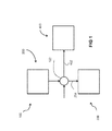
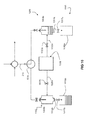
- Figure 1 is a flow diagram of an example fluid processing assembly
- Figure 2 is a flow diagram of the reactor assembly and product collection assembly of the fluid processing assembly of Figure 1 ;
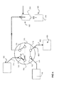
- Figure 3 is a flow diagram of a sample valve of the fluid processing assembly of Figure 1 , showing the sample valve in a first position;
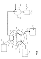
- Figure 4 is a flow diagram of the sample valve of Figure 3 , showing the sample valve in a second position;
- Figure 5 is a flow diagram of the sample valve of Figure 4 , showing the sample valve moved back to the first position from the second position;
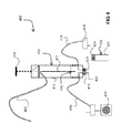
- Figure 6 is a schematic diagram of the sample collection assembly of Figure 1 , showing an actuator in a home position;
- Figure 7 is a schematic diagram of the sample collection assembly of Figure 6 , showing the actuator moved towards a sample collection vessel;
- Figure 8 is a schematic diagram of the sample collection assembly of Figure 7 , showing the actuator gripping a sample collection vessel;
- Figure 9 is a schematic diagram of the sample collection assembly of Figure 8 , showing the outlet end of a sample stream in a dispensing position;
- Figure 10 is a flow diagram of an alternate example of a product collection assembly, showing a shutoff valve in a first position
- Figure 11 is a flow diagram of the product collection assembly of Figure 10 , showing the shutoff valve in a second position;
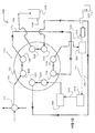
- Figure 12 is a flow diagram of another alternate example of a product collection assembly, showing a primary product collection valve in a first position;
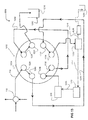
- Figure 13 is a flow diagram of the product collection assembly of Figure 12 , showing the primary product collection valve in a second position.
- the fluid processing assembly 100 generally includes a reactor assembly 200, a product collection assembly 300, and a sample collection assembly 400.
- the reactor assembly 200 includes a lumen 201, within which a reaction occurs.
- the lumen 201 is formed by a tube 202.
- the tube may be a capillary, for example a glass capillary.
- the lumen 201 may be pressurized by a downstream pressurized gas source (i.e. back pressure may be applied to the lumen).
- the lumen may be of any suitable construction, including, for example, a capillary, a tube/ conduit of any suitable cross-section (round, square, etc), and a channel in a chip.
- the lumen may be formed from any suitable material in whole or in part, including microwave radiation transparent materials (such as glass or alumina) whereby the microwave irradiation directly heat the product material, and/or microwave radiation absorbing materials (such as silicon carbide, graphite, charcoal, etc.) whereby the microwaves heat the lumen material which then heats the reactant/product material contained in the lumen.
- microwave radiation transparent materials such as glass or alumina
- microwave radiation absorbing materials such as silicon carbide, graphite, charcoal, etc.
- the lumen 201 receives an inlet stream 204.
- the inlet stream 204 flows into the lumen 201 from a mixer 206, which is in communication with a material supply array 208.
- the lumen 201 may receive more than one inlet stream, and mixing may occur within the lumen 201.
- the reactor assembly 200 further includes an energizing device 210 for supplying energy to an energizable portion 212 of the lumen 201.
- the energizing device may be an irradiating device which irradiates an irradiation zone, and the energizable portion 212 may be within the irradiation zone.
- the energizing device 210 is a microwave irradiating device 210. The microwave irradiating device 210 irradiates the energizable portion 212 of the lumen 201 with microwave irradiation.
- the microwave irradiation device can heat the contents of the energizable portion 212 of the lumen 201, and may facilitate a reaction.
- the material supply array 208 and mixer 206 may provide a solution of reactants to the lumen 201.
- the reactants When heated in the energizable portion 212 of the lumen 201 by the microwave irradiating device 210, the reactants may undergo a chemical reaction to yield one or more products.
- the lumen 201 may be pressurized in order to facilitate the reaction.
- the lumen may be pressurized in order to prevent or inhibit a phase change within the lumen, and to maintain the reactants in the liquid phase, which may facilitate the reaction.
- the microwave irradiating device 210 supplies energy to essentially the entirety of the lumen 201, and the entirety of the lumen 201 may be considered to be the energizable portion 212. In other examples, only a portion of the lumen 201 may be the energizable portion.
- the inlet and outlet ends of the lumen 201 may be positioned such that they are outside of the irradiation zone, and are not irradiated by the microwave irradiating device.
- a chemical reaction may occur within the lumen 201.
- other types of reactions may occur in the lumen 201.
- Such reactions may include, for example, pasteurization sterilization, or fluid derivation.
- the energizing device may be a microwave irradiating device.
- the energizing device may be an ultrasound device, a photo device such as a light, or a thermal device such as a heat exchanger, oven, resistive heating, inductive heaters, photo irradiation or heating tape.
- a primary product stream 214 containing the product(s) of the reaction, is dispensed from the lumen 201 and is directed to the product collection assembly 300.
- the product collection assembly 300 includes a primary product collection assembly 302, and a downstream bulk product collection assembly 305.
- the primary product collection assembly 302 is in fluid communication with the lumen 201 for receiving the primary product stream 214.
- at least a portion of the primary product collection assembly is pressurized by a pressurized gas source, which applies back pressure to the lumen 201.
- the downstream bulk product collection assembly 305 is, in the example illustrated, at atmospheric pressure.
- the primary product collection assembly 302 includes a primary product collection vessel 304.
- the primary product collection vessel 304 is pressurized and is generally sealed to the external atmosphere (i.e. in the example shown, the primary product collection vessel 304 is the portion of the primary product collection assembly 302 that is pressurized).
- a drip tube 306 is mounted within the primary product collection vessel 304. The drip tube 306 receives the primary product stream 214, and the primary product stream 214 drips from the drip tube 306 into the primary product collection vessel 304.
- the primary product collection vessel 304 is pressurized by a pressurized gas source, which in turn pressurizes (i.e. applies back pressure to) the primary product stream 214 and the lumen 201, and in order to facilitate the reaction in the lumen 201.
- a pressurized gas source pressurizes (i.e. applies back pressure to) the primary product stream 214 and the lumen 201, and in order to facilitate the reaction in the lumen 201.
- contact between the product stream and regulator can result in fouling of the regulator, which in some instances may interrupt the operation of the system. This may cause premature halting of a production run.
- backpressure is applied to the system by pressurizing the primary collection vessel 304, via a pressurized gas, with a sufficiently high pressure gradient to prevent backflow of product liquid into the gas system, and the liquid product stream is dripped into the pressurized primary product vessel 304 which eliminates the need for direct physical contact between a back pressure regulator and the product stream.
- a pressurized gas source 308 is connected to and supplies pressurized gas to the primary product collection vessel 304 to pressurize the primary product collection vessel 304, the drip tube 306, the primary product stream 214 and the lumen 201.
- the inlet stream 204 may be pressurized at a greater pressure than the back pressure supplied by the pressurized gas source.
- one or more pumps may be used to direct the inlet stream 204 into the lumen 201 at a greater pressure than the back pressure supplied by the pressurized gas source.
- the pressurized gas source may be of any suitable configuration.
- the pressurized gas source 308 includes a gas supply tank 310, a pressure ballast 312, and various check valves, shut-off valves, vents, and regulators.
- the pressurized gas may be, in some examples, an inert gas such as nitrogen or argon.
- the pressurized gas may be a reactive gas, and may, for example, participate in the reaction it the lumen.
- the reactor assembly 200 may be operated continuously, and the product collection assembly 300 may be operated semi-continuously.
- the reactor assembly 200 may be operated continuously, and the primary product collection vessel 304 may continuously receive the primary product stream 214 and semi-continuously dispense a bulk product stream 314 to the bulk product collection assembly 305.
- the product collection assembly 300 is configured such that the primary product stream 214 may continuously build up delivered product in the primary product collection vessel 304, until a desired volume is reached.
- the supply of pressurized gas may be shut-off, and an outlet valve 317 of the primary product collection vessel 304 may be opened to de-pressurize the system and to dispense the bulk product stream 314 from the primary product collection vessel 304 into a bulk product collection vessel 316 of the bulk product collection assembly 305.
- the outlet valve 317 may then be closed, and the system may be re-pressurized.
- the reactor assembly and product collection assembly may both be operated continuously.
- the primary product collection assembly may be configured to continuously dispense the bulk product stream into the bulk product collection vessel without depressurizing the system, so that the system can be run continuously.
- the energizable portion 212 of the lumen 201 is positioned exterior to the primary product collection assembly 302, and more specifically, exterior to the primary product collection vessel 304.
- the energizable portion 212 of the lumen 201 is not housed within the primary product collection vessel 304.
- the primary product collection vessel 304 may therefore optionally be non-transparent to microwave irradiation and/or more chemically resistant.
- the primary product collection vessel 304 may be made from a metal, metallic material or other material that is not suitable for use in forming the lumen 201. This may allow the product collection vessel 304 to have different mechanical and/or chemical properties from the lumen 201.
- the product collection vessel 304 may have higher heat resistance, greater strength, greater durability, and/or a greater chemical resistance, etc.
- the fluid processing assembly 100 further includes a valve 102 (also referred to as a sample valve) downstream of the lumen 201 and upstream of the primary product collection assembly 302, through which the primary product stream 214 flows.
- the valve is useable to divert a sample of the primary product stream 214 away from the primary product collection assembly 302 and to the sample collection assembly 400.
- the valve 102 is configured to divert the sample without de-pressurizing the primary product collection vessel 304 and the lumen 201.
- the valve 102 is a multi-port multi-position valve.
- the valve 102 is movable to direct the primary product stream 214 from the lumen 201 (shown in Figure 2 ) to the primary product collection assembly 302, isolate a plug 118 from the primary product stream 214, and divert the plug 118 to a sample stream 402 of the sample collection assembly 400, while generally maintaining the pressure in the lumen 201 and the primary product collection vessel 304.
- the phrase "maintaining the pressure” indicates that that while insignificant pressure fluctuations that do not materially affect the process may occur, substantial changes in pressure, such as depressurization to atmospheric pressure, do not occur.
- the valve 102 is a 6-port 2-position valve, and includes ports 104, 106, 108, 110, 112, and 114.
- the lumen 201 is in fluid communication with port 104
- the primary product collection assembly 302 is in fluid communication with port 106.
- a liquid solvent stream 115 from a solvent pump 116 is in fluid communication with port 112, and the sample stream 402 of the sample collection assembly 400 is in communication with port 114.
- the liquid solvent material like the liquid product material is generally understood to be incompressible, which can help facilitate pressurization of the system.
- the valve 102 is movable between a first position, shown in Figures 3 and 5 , and a second position, shown in Figure 4 .
- a first position shown in Figures 3 and 5
- a second position shown in Figure 4 .
- port 104 and port 106 are in fluid communication
- the primary product stream 214 is directed from the lumen 201 to the primary product collection assembly 302.
- ports 108, 110, 112, and 114 are in fluid communication, and solvent is directed from the solvent pump 116 to the sample stream 402.
- ports 104, 108, 110, and 106 are in fluid communication, and a loop defined between ports 108 and 110 is positioned in fluid communication with the reactor assembly 200 and is populated with liquid plug 118 from the primary product stream 214. While the system is in operation, the loop between ports 108 and 110 can become partially and/or completely filled with the reactant/ product stream. Further, when the valve 102 is in the second position, ports 112 and 114 are in fluid communication, and solvent continues to be directed from the solvent pump 116 to the sample stream 402.
- the primary product stream 214 is again directed from the lumen 201 to the primary product collection assembly 302, and the plug 118 is isolated from the primary product stream 214 and can be pushed with solvent from the solvent pump 116 towards to the sample stream 402.
- clean solvent can be pushed through the loop between ports 108 and 110 which may help clean the loop.
- the lumen 201 is in fluid communication with the primary product collection vessel 304, and in fluid isolation of the sample stream 402 and the exterior atmosphere.
- the valve 102 may be periodically moved from the first position to the second position (i.e. moved a first time), and from the second position back to the first position (i.e. moved a second time), in order to divert a sample of the primary product stream 214 away from the primary product collection assembly 302 and towards the sample collection assembly 400, while maintaining the pressure in the lumen 201 and the primary product collection vessel 304.
- the sample collection assembly 400 generally includes the sample stream 402, an automatic actuator 404, and a sample collection vessel 406.
- the sample stream 402 includes an inlet end portion 408 (shown in Figures 3 to 5 ), and an outlet end portion 410.
- the inlet end portion 408 is connectable in fluid communication with the primary product stream 214 upstream of the primary product collection assembly 302 for receiving a sample of the product.
- the inlet end portion 408 is connected to port 114 of the valve 102, so that when the valve 102 is moved from the first position, to the second position, and back to the first position, the inlet end portion 408 receives a sample of the primary product stream 214.
- the outlet end portion 410 of the sample stream 402 includes a fluid delivery conduit, which in the example illustrated is provided as a needle 411, which may be inserted into the sample collection vessel 406, as will be described in further detail below.
- the sample collection vessel 406 includes a glass vial 407 having a piercable stopper 409.
- the sample collection vessel 406 may be another suitable vessel, such as a test tube.
- the automatic actuator 404 is coupled to the outlet end portion 410, and is operable to move the outlet end portion 410 towards and away from a dispensing position (the dispensing position is shown in Figure 9 ).
- the needle 411 is inserted through the stopper 409 of the sample collection vessel 406, so that the outlet end portion 410 is in fluid communication with the sample collection vessel 406.
- the automatic actuator includes a movable frame 412 in which the needle is mounted, a robot (not shown) for moving the frame 412, a motor 413 for moving the needle 411 within the frame, and a vessel grip 415 for gripping the sample collection vessel 406
- the sample collection assembly 400 further includes a gas injection line 414 connectable in fluid communication with the sample collection vessel 406 for injecting gas into the sample collection vessel 406, and a gas withdrawal line 416 connectable in fluid communication with the sample collection vessel 406 for removing gas from the sample collection vessel 406.
- the gas injection line 414 may be connected to a gas source 418, such as an inert gas.
- the gas withdrawal line 416 may be connected to a vacuum pump 420. Both the gas injection line 414 and the gas withdrawal line 416 include a needle 421, 422, respectively, which may be inserted through the stopper of the sample collection vessel 406.
- the steps may be under automatic control, or may be carried out manually.
- the timing of the various steps may be based on the status of the valve 102.
- the steps may be initiated when the valve 102 is actuated to divert a sample to the sample stream 402.
- the robot may be engaged to move the frame 412 from a home position (shown in Figure 6 ), towards the sample collection vessel 406 (as shown in Figure 7 ).
- the robot may then move the frame 412 downwardly so that the needles 421, 422 are inserted through the stopper 409 of the sample collection vessel 406, and so that the vessel grip 415 grips the sample collection vessel 406 (as shown in Figure 8 ).
- the vacuum pump 420 may then be activated to purge the sample collection vessel 406 of the gas contained therein, and to fill the sample collection vessel 406 with the gas from the gas source 418 (e.g. an inert gas).
- the motor 413 may then be actuated to move the needle 411 to the dispensing position, as shown in Figure 9 , so that the sample is dispensed into the sample collection vessel 406.
- the sample collection assembly 400 may include a sample analysis apparatus (not shown), such as a gas or liquid chromatograph, optionally fitted with suitable technologies such as EI (electron ionization), CI (chemical ionization), ESI (electrospray ionization), APCI (atmospheric pressure chemical ionization), TCD (thermal conductivity detector), FID (flame ion detector), or CCD (catalytic combustion detector).
- suitable technologies such as EI (electron ionization), CI (chemical ionization), ESI (electrospray ionization), APCI (atmospheric pressure chemical ionization), TCD (thermal conductivity detector), FID (flame ion detector), or CCD (catalytic combustion detector).
- EI electron ionization
- CI chemical ionization
- ESI electrospray ionization
- APCI atmospheric pressure chemical ionization
- TCD thermal conductivity detector
- the sample collection vessel 406 may be transferred to sample analysis apparatus (for example by the robot), so that the sample analysis apparatus may withdraw a portion of the sample therefrom and analyze the portion.
- a portion of the sample may be transferred from the sample collection vessel 406 to another vessel, which may be received by the sample analysis apparatus.
- the sample collection assembly 400 may be configured to carry out various processing steps on the sample prior to forwarding a portion of the sample to the sample analysis apparatus. For example, various components, such as a solvent and/or a reactant, may be added to or removed from the sample (for example to concentrate the sample).
- Data derived from the analyses of the sample analysis apparatus can be provided to a platform of a system control manager platform (not shown) to rationally alter parameters of the fluid processing assembly (e.g., process temperature, flow-rate, stoichiometry, pressure, extracted sample volume, dilution volume, concentration, choice of dilutant, chemical contributors (e.g., reagents, catalysis, solvent, promoter) and any other factors that may influence the process). This may be done, for example, to optimize efficiency and/or minimize safety-related risks.
- the system control manager may be capable of controlling the fluid processing assembly with built-in artificial intelligence, using basic system algorithms as well as user-defined parameter boundaries.
- the system control manager platform may also be amenable to manual intervention, either on-site or from a remote location.
- valves or other components may be positioned in the sample stream 402 between the inlet end portion 408 and the outlet end portion 410.
- a valve may be positioned in the sample stream 402 for diverting the contents thereof to waste.
- the automatic actuator may be without a vessel grip.
- the frame may be positioned above the vessel, without gripping the vessel, and the various needles may pierce the stopper from this position.
- a vessel guide may be provided instead of a vessel grip. The vessel guide may aid in positioning aligning the frame above the vessel without gripping the vessel.
- the product collection assembly 1000 includes a primary product collection assembly 1002 configured to continuously receive the pressurized primary product stream 214 from the reactor assembly (not shown), and to continuously dispense a bulk product at atmospheric pressure to the bulk product collection assembly 1005, while maintaining the pressure in the lumen 201.
- the primary product collection assembly 1002 includes a first primary product collection vessel 1004a, and a second primary product collection vessel 1004b.
- a stream selector valve 1018 is downstream of the lumen 201 and upstream of the first 1004a and second 1004b primary product collection vessels.
- the stream selector valve 1018 is movable between a first position, shown in Figure 10 , where the primary product stream 214 is directed to the first primary product collection vessel 1004a, and a second position, shown in Figure 11 , where the primary product stream 214 is directed to the second primary product collection vessel 1004b.
- a pressurized gas source 1008 is connected to the first primary product collection vessel 1004a via a first pressure line 1020a and a first pressure valve 1022a, and to the second primary product collection vessel 1004b via a second pressure line 1020b and a second pressure valve 1022b.
- the pressurized gas source 1008 is operable to selectively supply pressurized gas to the first primary product collection vessel 1004a, and/or the second primary product collection vessel 1004b, to pressurize the first primary product collection vessel 1004a, and/or the second primary product collection vessel 1004b, as well as the lumen 201 and the primary product stream 214.
- Other suitable valving and hardware may be provided in the lines between the product collection vessel 1004a (or 1004b).
- control valves 1023a and 1023b may be provided between primary collection vessels 1004a and 1004b and the valve 1018.
- Providing control valves 1023a and 1023b may allow the primary collection vessels 1004a and 1004b to be isolated from the system, which may allow the primary collection vessels 1004a and 1004b to be emptied into the bulk collection vessels 1016a and 1016b without significantly depressurizing the system upstream from the control valves 1023a and 1023b, including portions of the lines provided between the control valves 1023a and 1023b and the valve 1018. This may help prevent pressure surges in the system when the control valves 1023a and 1023b are opened and closed.
- the bulk product collection assembly 1005 includes a first bulk product collection vessel 1016a and a second bulk product collection vessel 1016b, both of which are at atmospheric pressure.
- the first bulk product collection vessel 1016a receives bulk product from the first primary product collection vessel 1004a via a first bulk product stream 1014a
- the second bulk product collection vessel 1016b receives a bulk product from the second primary product collection vessel 1004b via a second bulk product stream 1014b.
- a first outlet valve 1017a is provided between the first primary product collection vessel 1004a and the first bulk product collection vessel 1016a
- a second outlet valve 1017b is provided between the second primary product collection vessel 1004b and the second bulk product collection vessel 1016b.
- the first 1017a and second 1017b outlet valves may be selectively opened or closed to control the flow of the bulk product between the first primary product collection vessel 1004a and the first bulk product collection vessel 1016a, and the second primary product collection vessel 1004b and the second bulk product vessel 1016b, respectively.
- a single bulk product collection vessel 1016 (shown using dashed lines in Figure 11 ) may be provided to collection the product from both primary collection vessels. This may be advantageous during production when the product is to be produced and collected as defined batches.
- the stream selector valve 1018 may be positioned in the first position, so that primary product stream 214 is directed to the first primary product collection vessel 1004a, and is in fluid isolation of the second primary product collection vessel 1004b.
- the first pressure valve 1022a may be positioned so that pressurized gas is supplied to the first primary product collection vessel 1004a, and the first outlet valve 1017a may be closed, so that the first primary product collection vessel 1004a, the lumen 201, and the primary product stream 214 are pressurized.
- the reactor assembly 200 may be continuously operated, and the primary product stream 214 may flow into the primary product collection vessel 1004a.
- the second pressure valve 1022b may be positioned so that pressurized gas is supplied to the second primary product collection vessel 1004b, and the second outlet valve 1017b may be closed, so that the second primary product collection vessel 1004b is pressurized.
- the stream selector valve 1018 may then be moved to the second position, so that the primary product stream 214 is directed to the second primary product collection vessel 1004b, and the pressure in the lumen 201 is maintained.
- the reactor assembly 200 may continue to be operated, and the primary product stream 214 will flow into and be contained within the second primary product collection vessel 1004b.
- the first pressure valve 1022a may be positioned so that the supply of pressurized gas to the first primary product collection vessel 1004a is stopped.
- the first outlet valve 1017a may then be opened, so that the product in the first primary product collection vessel 1004a flows into the first bulk product stream 1014a and is collected in the first bulk product collection vessel 1016a.
- the various valves may be switched back to the positions shown in Figure 10 , so that the lumen 201 remains pressurized and directs the primary product stream 214 to the first primary product collection vessel 1004a, and the product in the second primary product collection vessel 1004b flows through the second bulk product stream 1014b and is collected in the second bulk product collection vessel 1016b.
- the primary product collection assembly 1002 may continuously receive the pressurized primary product stream 214 from the reactor assembly 200, and continuously dispense a bulk product at atmospheric pressure to the bulk product collection assembly 1005, while the pressure in the lumen 201 is maintained.
- the primary product collection assembly 1202 includes a valve 1224 downstream of the lumen 201 and the sample valve 102 for receiving the primary product stream 214.
- the valve 1224 may also be referred to as primary product collection valve 1224.
- the primary product collection assembly 1202 is configured to continuously receive the pressurized product stream 214 from the reactor assembly 200, and to continuously dispense a bulk product at atmospheric pressure to the bulk product collection assembly 1205, while maintaining the pressure in the lumen 201.
- the valve 1224 may be a multi-port multi-position valve.
- the valve is an eight-port two-position valve, having ports 1226, 1228, 1230, 1232, 1234, 1236, 1238, and 1240.
- the valve 1224 includes a first loop 1242, between ports 1228 and 1236, and a second loop 1244, between ports 1232 and 1240.
- port 1226 is connected in fluid communication with the lumen 201 and the primary product stream 214
- port 1230 is connected in fluid communication with a bulk product collection vessel 1216 at atmospheric pressure
- port 1234 is connected in fluid communication with a pressurized gas source 1208, and port 1238 is connected to a pump 1246.
- the valve 1224 is movable between a first position, shown in Figure 12 , and a second position, shown in Figure 13 .
- port 1226 when in the first position, port 1226 is connected to port 1228, port 1230 is connected to port 1232, port 1234 is connected to port 1236, and port 1238 is connected to port 1240.
- the first loop 1242 is in fluid communication with the lumen 201 via the primary product stream 214, as well as the pressurized gas source 1208.
- the second loop 1244 is in fluid communication with the pump 1246 and the bulk product collection vessel 1216.
- the pressurized gas source will pressurize the first loop 1242, and re-establishes the fluid communication between the primary product stream 214, and the lumen 201, and the primary product stream 214 will flow into the first loop 1242. If the pump 1246 is operated, the contents of the second loop 1244 will flow towards the bulk product collection vessel 1216 of the bulk product collection assembly 1205.
- the valve When the contents of the first loop reach port 1236, the valve may be moved to the second position, shown in Figure 13 .
- port 1226 When in the second position, port 1226 is connected to port 1240, port 1228 is connected to port 1230, port 1232 is connected to port 1234, and port 1236 is connected to port 1238.
- the first loop 1242 is in fluid communication with the pump 1246 and the bulk product collection vessel 1216
- the second loop 1244 is in fluid communication with the lumen 201 via the primary product stream 214, as well as the pressurized gas source 1208.
- the pressurized gas source 1208 If the reactor assembly 200 continues to operate, the pressurized gas source 1208 will pressurize the second loop 1244 and the lumen 201, and the primary product stream 214 will flow into the second loop 1244.
- the pump 1246 continues to operate, the contents of the first loop 1242, which was filled with product from the primary product stream 214 when the valve 1224 was previously in the first position, will be pumped towards bulk product collection vessel 12
- the primary product collection assembly 1202 may continuously receive and pressurize the primary product stream 214 from the reactor assembly 200, and continuously dispense a bulk product at atmospheric pressure to the bulk product collection assembly 1205, while the pressure in the lumen 201 is maintained.
- the actuation of the valve 1224 may be automatically controlled, for example by a computer, and the timing of the actuation may be determined by the computer based on the size of the loop.
- the primary product collection assembly does not include a primary product collection vessel.
- first loop and second loop are external to the body of the valve 1224, and may be variable in size. In alternate examples, the first loop and second loop may be internal to the body of the valve 1224.
- some or all of the solvent or any other suitable inert fluid used by the pump 1246 to drive product out of the product filling loop 1244 in Figure 12 or loop 1242 in Figure 13 and into vessel 1216 can be temporarily accumulated and/or held in a portion of the pressurized gas source 1208.
- the accumulated fluid can be intermittently or continuously withdrawn from the pressurized gas source 1208.
- the solvent collected in the pressurized gas source 1246 may be removed from the system and discarded, or alternatively at least a portion of the accumulated fluid may be recycled back into the system. The recycled fluid may be reintroduced in to the system at any suitable location and/or using any suitable means.
- the pressurized gas source 1208 is in fluid communication with a multistage pressure controlling device 1211 via an exit line 1219.
- Device pressure controlling device 1211 is capable of accepting and momentarily isolating the inert liquid from 1208 before draining the liquid into a collection vessel 1221. This may help facilitate removal of fluid from the system without causing significant depressurization of the system.
- the collection vessel 1211 can also help facilitate this process with the aid of any suitable back-pressure generating barrier.
- At least a portion of the accumulated solvent can be reintroduced to the system, for example via a recycling line 1217 which is connected to the pump 1246 (either upstream or downstream from the pump 1246) stream either manually or through valves.
- the system includes an optional recycle stream carried in recycle line 1217 (shown using dashed lines) that is configured to facilitate unidirectional flow. This may help prevent fluid from flowing from the pump 1246 to the pressurized gas source 1208 via the recycle line 1217.
- the system may be provided with any suitable flow regulating apparatus, including, for example, a check valve 1213.
- various additional valves can be included in various positions in the assembly.
- one or more additional valves may be positioned in the primary product stream or in the bulk product stream for diverting a second sample of the product to the sample collection assembly, or for diverting a portion of the product to waste.
Landscapes
- Chemical & Material Sciences (AREA)
- Life Sciences & Earth Sciences (AREA)
- General Health & Medical Sciences (AREA)
- Health & Medical Sciences (AREA)
- Physics & Mathematics (AREA)
- Analytical Chemistry (AREA)
- Pathology (AREA)
- Immunology (AREA)
- Biochemistry (AREA)
- General Physics & Mathematics (AREA)
- Organic Chemistry (AREA)
- Chemical Kinetics & Catalysis (AREA)
- Engineering & Computer Science (AREA)
- Electromagnetism (AREA)
- Toxicology (AREA)
- Polymers & Plastics (AREA)
- Food Science & Technology (AREA)
- Zoology (AREA)
- Wood Science & Technology (AREA)
- Physical Or Chemical Processes And Apparatus (AREA)
- Meat, Egg Or Seafood Products (AREA)
Applications Claiming Priority (1)
| Application Number | Priority Date | Filing Date | Title |
|---|---|---|---|
| US201261703822P | 2012-09-21 | 2012-09-21 |
Publications (2)
| Publication Number | Publication Date |
|---|---|
| EP2711076A2 true EP2711076A2 (fr) | 2014-03-26 |
| EP2711076A3 EP2711076A3 (fr) | 2016-05-25 |
Family
ID=49385099
Family Applications (1)
| Application Number | Title | Priority Date | Filing Date |
|---|---|---|---|
| EP13185455.6A Withdrawn EP2711076A3 (fr) | 2012-09-21 | 2013-09-20 | Appareil de traitement de fluide |
Country Status (2)
| Country | Link |
|---|---|
| US (1) | US9579625B2 (fr) |
| EP (1) | EP2711076A3 (fr) |
Cited By (2)
| Publication number | Priority date | Publication date | Assignee | Title |
|---|---|---|---|---|
| FR3080047A1 (fr) * | 2018-04-16 | 2019-10-18 | Institut National Polytechnique De Toulouse | Dispositif de reaction en flux continu chauffee par micro-ondes comportant un reacteur en carbure de silicium |
| WO2021162552A1 (fr) | 2020-02-14 | 2021-08-19 | Technische Universiteit Delft | Agencement d'échantillonnage |
Families Citing this family (6)
| Publication number | Priority date | Publication date | Assignee | Title |
|---|---|---|---|---|
| US12491261B2 (en) | 2016-10-26 | 2025-12-09 | Acuitas Therapeutics, Inc. | Lipid nanoparticle formulations |
| US11680955B2 (en) * | 2018-04-04 | 2023-06-20 | Total Synthesis Ltd. | Fluid diverting module |
| IL281615B2 (en) * | 2018-09-21 | 2026-01-01 | Acuitas Therapeutics Inc | Systems and methods for producing lipid nanoparticles and liposomes |
| CA3116576A1 (fr) | 2018-10-18 | 2020-04-23 | Acuitas Therapeutics, Inc. | Lipides pour l'administration de nanoparticules lipidiques d'agents actifs |
| ES3054438T3 (en) | 2020-07-16 | 2026-02-03 | Acuitas Therapeutics Inc | Cationic lipids for use in lipid nanoparticles |
| GB2639964A (en) * | 2024-03-28 | 2025-10-08 | Keymed Medical & Industrial Equipment Ltd | Apparatus and method for treating an insufflation gas |
Citations (3)
| Publication number | Priority date | Publication date | Assignee | Title |
|---|---|---|---|---|
| US5672316A (en) | 1994-03-11 | 1997-09-30 | Knapp; Gunter | Microwave-heatable pressure reactor |
| US7178414B1 (en) | 2004-02-27 | 2007-02-20 | Kokosa John M | Automation of liquid phase microextraction |
| US20070210067A1 (en) | 2006-02-21 | 2007-09-13 | Patterson Wade C | Water Heating Systems and Methods for Detecting Dry Fire Conditions |
Family Cites Families (41)
| Publication number | Priority date | Publication date | Assignee | Title |
|---|---|---|---|---|
| US3213669A (en) | 1963-02-28 | 1965-10-26 | Wilkens Instr & Res Inc | Automatic sample collecting apparatus |
| US3939406A (en) | 1973-06-13 | 1976-02-17 | Westinghouse Electric Corporation | Microwave fluid flow meter |
| US4271697A (en) | 1979-10-17 | 1981-06-09 | Phillips Petroleum Company | Chromatographic analysis |
| US4478095A (en) | 1981-03-09 | 1984-10-23 | Spectra-Physics, Inc. | Autosampler mechanism |
| JPS5887464A (ja) | 1981-11-20 | 1983-05-25 | Hitachi Ltd | 連続流れ方式自動分析方法 |
| US4678639A (en) | 1984-03-02 | 1987-07-07 | The Perkin-Elmer Corporation | Apparatus for periodically monitoring the composition of a plurality of samples |
| US4975246A (en) | 1985-09-30 | 1990-12-04 | Charm Stanley E | High temperature, short time heating system and method of heating heat-sensitive material |
| US4713974A (en) | 1986-04-18 | 1987-12-22 | Varian Associates, Inc./Scientific Systems, Inc. | Autosampler |
| US4816226A (en) | 1987-12-30 | 1989-03-28 | Shell Oil Company | Apparatus for continuous flow injection solvent extraction analysis |
| US4930898A (en) | 1988-06-27 | 1990-06-05 | The United States Of America As Represented By The Secretary Of Agriculture | Process and apparatus for direct ultrasonic mixing prior to analysis |
| JP2899979B2 (ja) | 1990-01-26 | 1999-06-02 | 日本原子力発電株式会社 | 高温ガス炉 |
| DE4143541C2 (de) | 1991-02-19 | 1999-03-04 | Mls Gmbh | Vorrichtung zum Extrahieren von Proben mittels eines Lösungsmittels bei erhöhter Temperatur |
| US5215715A (en) | 1991-07-10 | 1993-06-01 | Cem Corporation | Microwave heated digesting system for digesting materials to be analyzed |
| US5420039A (en) | 1992-12-31 | 1995-05-30 | Cem Corporation | Control of continuous microwave digestion process |
| US5389335A (en) | 1993-06-18 | 1995-02-14 | Charm Sciences, Inc. | High temperature, short time microwave heating system and method of heating heat-sensitive material |
| JP3512811B2 (ja) | 1994-07-11 | 2004-03-31 | テクマー カンパニー | モジュール式バイアル自動サンプル装置 |
| CA2214263A1 (fr) | 1995-03-07 | 1996-09-12 | Biomolecular Assays, Inc. | Reacteur a cycle de pression |
| US5814742A (en) | 1996-10-11 | 1998-09-29 | L C Packings, Nederland B.V. | Fully automated micro-autosampler for micro, capillary and nano high performance liquid chromatography |
| US6260407B1 (en) | 1998-04-03 | 2001-07-17 | Symyx Technologies, Inc. | High-temperature characterization of polymers |
| US6203760B1 (en) | 1999-02-12 | 2001-03-20 | Perkinelmer Instruments Llc | Autosampler having gripper with shape memory metal actuator |
| US6706245B2 (en) | 2000-03-10 | 2004-03-16 | Teledyne Tekmar Company | Three stage needle for use with an autosampler |
| US6736783B2 (en) | 2000-04-12 | 2004-05-18 | Merck & Co., Inc. | Automated blood sampling apparatus |
| US20030198578A1 (en) | 2002-04-18 | 2003-10-23 | Dielectric Systems, Inc. | Multi-stage-heating thermal reactor for transport polymerization |
| US20050123970A1 (en) | 2001-04-25 | 2005-06-09 | Can Ozbal | High throughput autosampler |
| US6740858B2 (en) | 2001-06-01 | 2004-05-25 | Communications And Power Industries, Inc. | Microwave heating applicator for heating a moving fluid |
| DE10128038C1 (de) | 2001-06-08 | 2002-11-21 | Karlsruhe Forschzent | Mikrowellentechnischer Durchlauferhitzer |
| US20030091487A1 (en) | 2001-10-19 | 2003-05-15 | Magnus Fagrell | Continuous flow heating system |
| US6863805B1 (en) * | 2002-11-27 | 2005-03-08 | Francisco J. Barreras, Sr. | Automated, self-contained, home sewage treatment system |
| US20050019216A1 (en) | 2003-07-24 | 2005-01-27 | Hans-Heinrich Trutnau | Apparatus for introducing a sample into a flowthrough analysis system |
| US7488464B2 (en) | 2003-07-31 | 2009-02-10 | Enviroscrub Technologies Corporation | Metal oxide processing methods and systems |
| US6989519B2 (en) | 2003-09-02 | 2006-01-24 | Cem Corporation | Controlled flow instrument for microwave assisted chemistry with high viscosity liquids and heterogeneous mixtures |
| JP4155218B2 (ja) | 2004-03-30 | 2008-09-24 | 株式会社島津製作所 | オートサンプラ |
| US20050274065A1 (en) | 2004-06-15 | 2005-12-15 | Carnegie Mellon University | Methods for producing biodiesel |
| WO2006024167A1 (fr) | 2004-08-31 | 2006-03-09 | Total Synthesis Ltd. | Procede et appareil pour realiser des reactions chimiques a microechelle |
| US7700046B2 (en) | 2004-09-14 | 2010-04-20 | Goldenberg Alec S | Controlled additive/reactant delivery system |
| EP1915214A4 (fr) | 2005-08-11 | 2017-11-08 | GlaxoSmithKline LLC | Reacteur continu et procede de reaction |
| NO20055456L (no) | 2005-11-17 | 2007-05-18 | Fluens Synthesis As | Kontinuerlig stromningsreaktor |
| JP4992401B2 (ja) | 2006-12-06 | 2012-08-08 | 株式会社島津製作所 | オートサンプラ洗浄機構 |
| WO2009048642A1 (fr) | 2007-10-11 | 2009-04-16 | Accelbeam Devices Llc | Réacteur à micro-ondes |
| DE102007059651B4 (de) | 2007-12-10 | 2017-05-24 | Dionex Softron Gmbh | Probengeber für die Hochleistungsflüssigkeitschromatographie |
| JP4675406B2 (ja) * | 2008-09-29 | 2011-04-20 | 日本分光株式会社 | 超臨界流体システムにおける試料回収容器と、試料回収装置および試料回収方法 |
-
2013
- 2013-09-20 EP EP13185455.6A patent/EP2711076A3/fr not_active Withdrawn
- 2013-09-20 US US14/032,575 patent/US9579625B2/en not_active Expired - Fee Related
Patent Citations (3)
| Publication number | Priority date | Publication date | Assignee | Title |
|---|---|---|---|---|
| US5672316A (en) | 1994-03-11 | 1997-09-30 | Knapp; Gunter | Microwave-heatable pressure reactor |
| US7178414B1 (en) | 2004-02-27 | 2007-02-20 | Kokosa John M | Automation of liquid phase microextraction |
| US20070210067A1 (en) | 2006-02-21 | 2007-09-13 | Patterson Wade C | Water Heating Systems and Methods for Detecting Dry Fire Conditions |
Cited By (3)
| Publication number | Priority date | Publication date | Assignee | Title |
|---|---|---|---|---|
| FR3080047A1 (fr) * | 2018-04-16 | 2019-10-18 | Institut National Polytechnique De Toulouse | Dispositif de reaction en flux continu chauffee par micro-ondes comportant un reacteur en carbure de silicium |
| WO2021162552A1 (fr) | 2020-02-14 | 2021-08-19 | Technische Universiteit Delft | Agencement d'échantillonnage |
| NL2024908B1 (en) * | 2020-02-14 | 2021-09-15 | Univ Delft Tech | Sampling arrangement |
Also Published As
| Publication number | Publication date |
|---|---|
| EP2711076A3 (fr) | 2016-05-25 |
| US20140087036A1 (en) | 2014-03-27 |
| US9579625B2 (en) | 2017-02-28 |
Similar Documents
| Publication | Publication Date | Title |
|---|---|---|
| US9579625B2 (en) | Fluid processing apparatus | |
| US5432098A (en) | Apparatus, and process, for automatically sampling solids and semi-solids materials for analysis | |
| US6436720B1 (en) | Residence time providing module/apparatus | |
| EP2585218B1 (fr) | Dispositif et procédé d'échantillonnage | |
| US20130342203A1 (en) | Spectroscopic sample analyzer and sample handling system | |
| US8497683B2 (en) | Spectroscopic sample analyzer and sample handling system | |
| CN111624280B (zh) | 一种自动配制气体标准曲线的装置和方法 | |
| WO1996027417A1 (fr) | Procede et appareil d'extraction automatisee d'analyte | |
| CN103448374B (zh) | 流路内气泡减少装置以及方法、液体供给装置及色谱装置 | |
| US5393492A (en) | Microwave chemical reactor for sample analysis | |
| CA2951398A1 (fr) | Procede d'assurance de parametres automatise aux points d'identification multiples | |
| US7837943B2 (en) | Device and method for pre-treating and injecting liquid specimen | |
| US6475437B1 (en) | Method and system for preparing samples for gas chromatography | |
| EP2992335B1 (fr) | Procédés d'échantillonnage de récipients non-atmosphériques dans un système de réacteurs parallèles | |
| WO2001036967A2 (fr) | Station de travail destinee a analyser le contenu d'une bombe aerosol | |
| US11060958B2 (en) | Sample preparation system | |
| WO2007021818A2 (fr) | Reacteur continu et procede de reaction | |
| CN217828949U (zh) | 多通道压力溶剂萃取仪系统流路 | |
| JP5447332B2 (ja) | 試料採取装置及び試料採取方法 | |
| WO2003095087A1 (fr) | Dispositif d'echantillonnage | |
| CN215115421U (zh) | 一种水质样品前处理装置 | |
| CN111701552B (zh) | 一种多功能光化学反应实验装置 | |
| CN202133580U (zh) | 一种用于全自动糖化血红蛋白分析仪的加热机构 | |
| CN114130328A (zh) | 光热协同连续相催化系统 | |
| EP1710572A1 (fr) | Procede et dispositif pour l' injection d'echantillon |
Legal Events
| Date | Code | Title | Description |
|---|---|---|---|
| PUAI | Public reference made under article 153(3) epc to a published international application that has entered the european phase |
Free format text: ORIGINAL CODE: 0009012 |
|
| AK | Designated contracting states |
Kind code of ref document: A2 Designated state(s): AL AT BE BG CH CY CZ DE DK EE ES FI FR GB GR HR HU IE IS IT LI LT LU LV MC MK MT NL NO PL PT RO RS SE SI SK SM TR |
|
| AX | Request for extension of the european patent |
Extension state: BA ME |
|
| PUAL | Search report despatched |
Free format text: ORIGINAL CODE: 0009013 |
|
| AK | Designated contracting states |
Kind code of ref document: A3 Designated state(s): AL AT BE BG CH CY CZ DE DK EE ES FI FR GB GR HR HU IE IS IT LI LT LU LV MC MK MT NL NO PL PT RO RS SE SI SK SM TR |
|
| AX | Request for extension of the european patent |
Extension state: BA ME |
|
| RIC1 | Information provided on ipc code assigned before grant |
Ipc: A23L 3/01 20060101ALN20160418BHEP Ipc: G01N 35/10 20060101ALN20160418BHEP Ipc: B01J 19/00 20060101ALN20160418BHEP Ipc: B01J 19/12 20060101AFI20160418BHEP Ipc: G01N 1/44 20060101ALI20160418BHEP |
|
| STAA | Information on the status of an ep patent application or granted ep patent |
Free format text: STATUS: THE APPLICATION HAS BEEN PUBLISHED |
|
| STAA | Information on the status of an ep patent application or granted ep patent |
Free format text: STATUS: THE APPLICATION IS DEEMED TO BE WITHDRAWN |
|
| 18D | Application deemed to be withdrawn |
Effective date: 20161126 |