EP2711082A2 - Hydrocyclone - Google Patents
Hydrocyclone Download PDFInfo
- Publication number
- EP2711082A2 EP2711082A2 EP13004254.2A EP13004254A EP2711082A2 EP 2711082 A2 EP2711082 A2 EP 2711082A2 EP 13004254 A EP13004254 A EP 13004254A EP 2711082 A2 EP2711082 A2 EP 2711082A2
- Authority
- EP
- European Patent Office
- Prior art keywords
- inflow
- space
- cyclone
- hydrocyclone
- phase mixture
- Prior art date
- Legal status (The legal status is an assumption and is not a legal conclusion. Google has not performed a legal analysis and makes no representation as to the accuracy of the status listed.)
- Withdrawn
Links
- 239000000203 mixture Substances 0.000 claims abstract description 44
- 230000003189 isokinetic effect Effects 0.000 claims abstract description 11
- 230000009969 flowable effect Effects 0.000 claims abstract description 6
- 238000000926 separation method Methods 0.000 claims description 7
- 125000004122 cyclic group Chemical group 0.000 abstract 2
- 238000011144 upstream manufacturing Methods 0.000 abstract 1
- 239000012530 fluid Substances 0.000 description 10
- 239000007788 liquid Substances 0.000 description 7
- 239000007787 solid Substances 0.000 description 4
- 230000000694 effects Effects 0.000 description 3
- 238000000034 method Methods 0.000 description 2
- 230000015572 biosynthetic process Effects 0.000 description 1
- 230000003068 static effect Effects 0.000 description 1
Images



Classifications
-
- B—PERFORMING OPERATIONS; TRANSPORTING
- B04—CENTRIFUGAL APPARATUS OR MACHINES FOR CARRYING-OUT PHYSICAL OR CHEMICAL PROCESSES
- B04C—APPARATUS USING FREE VORTEX FLOW, e.g. CYCLONES
- B04C5/00—Apparatus in which the axial direction of the vortex is reversed
- B04C5/02—Construction of inlets by which the vortex flow is generated, e.g. tangential admission, the fluid flow being forced to follow a downward path by spirally wound bulkheads, or with slightly downwardly-directed tangential admission
- B04C5/04—Tangential inlets
Definitions
- the invention relates to a hydrocyclone, in particular DC hydrocyclone, for separating a flowable mixture of a plurality of phases having different densities, comprising at least one inflow space for supplying the phase mixture réelletParkden with a predetermined inflow in at least one subsequent to the respective inflow space cyclone space, which of the phase mixture for separation cyclonic through-flow, wherein the inflow space and / or the cyclone space is associated with at least one molded part, which on the phase mixture with the predetermined inflow for dividing into at least one tangential velocity component and at least one Axial yorkskomponente on or flowed through.
- a hydrocyclone also called separation apparatus or centrifugal separator
- the individual phases are accelerated to different degrees according to their respective density in the cyclone space, so that a denser phase is transported radially outward and a less dense phase radially inward.
- a denser phase is withdrawn at the outer edge of the cyclone space and a less dense phase from the inside and the middle of the cyclone space.
- the individual phases which are initially mixed with one another can in each case be solid, liquid or gaseous, the solids generally being suspended in a liquid or a gas. through the hydrocyclone separations between liquid / liquid, solid / liquid and liquid / gas can be made, with even more phases can be separated, so for example solid / liquid / gaseous.
- the energy required for the separation work is supplied in the form of kinetic energy.
- the flow path also called process path
- the phases in the cyclone space and the corresponding speed components are given.
- energy losses occur in particular due to friction and flow resistance at the respective part. Therefore, embodiments with the lowest possible energy losses are aimed at the molded parts.
- the flowable mixture is braked by friction on the apparatus walls or wall parts, which is why a minimization of the surface of the wall contact is desirable.
- local speed differences may occur along the flow or process path of the phase mixture or of the phases to be separated in the cyclone space, which may lead to an undesired remixing, in other words backmixing, of the individual phases.
- a known, generic hydrocyclone formed a specially shaped, double tangential inlet.
- the two inlets each have a spiral ramp inclined with respect to the inflow plane and leading to the cyclone space.
- a flow behavior is generated in the cyclone space, that in a radially outer region, a larger axial velocity component than in a radially inner region Range is specified.
- a turbulence-free inflow of the phase mixture is ensured in the cyclone space.
- the invention has the object, with a low design effort to minimize backmixing of the cyclone space to be separated phases while keeping the energy losses when influencing the flow at the respective molded part low.
- a hydrocyclone according to the invention is characterized in that at least one of the parts is shaped in such a way that the phase mixture supplied to the respective cyclone chamber has an iso-kinetic flow behavior with an essentially constant axial velocity component at least in a cyclone region directly adjoining the respective inflow chamber. Due to the substantially constant axial velocity of the phase mixture to be separated, at least in the inlet or near-inlet cyclone region, differences in velocity are eliminated or at least reduced and the corresponding backmixing effects in the cyclone space are minimized.
- At least one of the parts can be shaped such that the phase mixture, at least in the cyclone region, has a further iso-kinetic flow behavior such that the respective tangential velocity components predetermine a substantially constant angular velocity in a respective radial plane relative to the cyclone space.
- the inventive design of the hydrocyclone is achieved in particular that the amount of static central fluid is minimized and ideally no longer exists, since no fluid elements in the cyclone region have a lower velocity than the local inlet velocity or the respective velocity component of the inflow velocity, that the axial velocity in the cyclone region in each radial plane is substantially the same, and that forms at least in the cyclone region, a flow, similar to a rigid body flow at a substantially constant angular velocity.
- a hydrocyclone invention improves.
- the respective part in at least one of the direction of the inflow, preferably perpendicular, cutting plane at least partially follows a, preferably concave, curved course.
- the part formed to form an iso-kinetic flow behavior is, for example, a wall part which can be flowed by the phase mixture, the term "flowable” also encompassing the term "flow around" or a fluid opening through which the phase mixture flows, such as an inflow opening.
- a design according to the invention of the hydrocyclone can be achieved with a low constructional outlay.
- the respective plane intersecting the inflow direction defines a cross-sectional area of the flow path or flow space of the supplied inflowing phase mixture.
- D to is the diameter of the feed pipe.
- D 0 is the maximum diameter of the cyclone space and corresponds to the extent of the inner diameter of the cyclone space predetermining cylindrical segment or a corresponding main pipe of the hydrocyclone.
- B is to the width (in y-direction), and Z to the height (in z-direction).
- D to the diameter of the inflow or the tangential inlet, in particular in the form of a feed pipe, in relation to the axial axis of the cyclone space or the hydrocyclone is specified.
- the diameter D (z) of the wall portion predetermining the cyclone area is a function of the height z, starting from a lower side of the rectangular inflow geometry associated with the further cyclone space.
- the profile given above results in the course of a fluid opening or the marginal areas which predetermine the same, wherein the corresponding fluid opening is preferably arranged in a plane which perpendicularly intersects the inflow direction.
- At least one inflow opening to be flowed through by the phase mixture to be supplied is provided between the respective inflow space and the respective cyclone space.
- the respective inflow opening can at least partially follow the curved course. In this way, the setting of an iso-kinetic flow behavior of the cyclone chamber supplied or flowing into this phase mixture is particularly simple.
- At least one wall part is associated with the wall contour following the curved course, in particular with the respective wall part with the correspondingly curved wall contour being arranged adjacent to the respective inflow opening.
- a particularly compact design of a hydrocyclone according to the invention is achieved in that the respective inflow opening and / or the respective wall part is formed on at least one insert part, which forms the respective inflow space and the respective cyclone space in each case at least partially in the hydrocyclone.
- Such an insert can be made to meet requirements and assembled in a modular manner with other components, such as cylindrical and conical segments, to form a hydrocyclone according to the invention.
- the invention further relates to such an insert for a hydrocyclone.
- the respective insert part may comprise a cylindrical part or a cone part, in the outer jacket of which the respective inflow opening is formed, and the interior of which, preferably adjacent to the respective inflow opening, has at least one inner wall part for forming the cyclone area for the associated cyclone space.
- Parts molded according to the invention may be the respective inflow opening, at least one inner wall part assigned to the cyclone space, and / or at least one outer wall part assigned to the inflow space, and each correspondingly curved Contour, here an opening contour or a wall contour, have.
- Fig. 1a shows a hydrocyclone 10 with an inlet 12 as a fluid inlet for a phase mixture, an underflow 14 and an upper reaches 16 as fluid outputs for separate phases.
- the hydrocyclone 10 is modularly composed of several components or components, two first cylindrical segments 18a, 18b, a first conical segment 20, a second cylindrical segment 22, a second conical segment 24 and a third cylindrical segment 26.
- the two of the inlet 12th associated first cylindrical segments 18a, 18b form an inflow 28 for the incoming via the inlet 12 into the hydrocyclone 10 phase mixture.
- Fig. 1b are individual components or components of in Fig. 1a shown as a whole hydrocyclone 10 shown.
- a circular opening 33 is formed as a fluid inlet.
- the presentation of the Fig. 1 b shows that on the first cylindrical segment 18a, two tangential inlets 12a, 12b, which are typically point symmetrical to Rotation axis R of the hydrocyclone 10 are arranged, may be formed.
- One or two flange-type connecting parts 36 are respectively formed on the respective component or the respective component.
- FIG. 1b Furthermore, an insert 38 is shown, which in the in Fig. 1a shown, assembled state of the hydrocyclone 10 within the in Fig. 1a lower first cylindrical segment 18b is arranged.
- the insert part 38 has, in addition to its connecting part 36, a cylindrical part 39, in whose outer jacket an inflow opening 40 is formed.
- an inner wall portion 47 is formed, which in this respect the cyclone space 30 partially, more precisely, the upper end portion predetermines.
- the inner wall part 47 is rotationally symmetrical to the axis of rotation R and inclined to this.
- the inflow opening 40 and the inner wall part 47 By the parts thus formed and arranged, the inflow opening 40 and the inner wall part 47, an inflow velocity 48 of the incoming at the inlet 12a in the tangential direction phase mixture in an axial velocity component, parallel to the axis of rotation R, and in a Tangential yorkskomponente, in a radial plane to the rotation axis R running, split.
- the cyclonic flow of the phase mixture or of the phases in the cyclone space 30 is predetermined and the energy required for the separation of the individual phases is generated from the kinetic energy of the phase mixture fed to the cyclone space 30 from the inflow space 28.
- a radially inwardly guided phase is drawn off at a lower density via an inner tube 35 of the upper run 16 downwards.
- a conically tapering inner part 34 projecting into the second conical segment 24 may be formed on the third cylindrical segment 26.
- About the lower reaches 14 is in the range of Third cylindrical segment 26 a radially outwardly guided phase with a higher density tangentially or radially withdrawn to the outside.
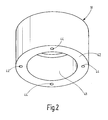
- Fig. 2 shows another cylindrical segment 18 for a hydrocyclone according to the invention.
- the cylindrical segment 18 is hood-like with a lid on the top and an opening 41 formed on the bottom. Attachment holes 44 for connecting the cylindrical segment 18 to further segments or components of the hydrocyclone 10 are formed on the lower end face 42.
- the hood-like cylindrical segment 18 can be placed on a in Fig. 1 b exemplarily shown insert 38 are placed and thus form an inflow, wherein the cylindrical segment 18 trainees, preferably tangential inlet in Fig. 2 not shown.
- Fig. 3a shows a perspective view of a first embodiment of an inventively designed insert part 38.
- the insert part 38 has a cylinder part 39 and a flange-like connecting part 36.
- the insert 38 may define an inflow space 28 in a hydrocyclone 10.
- the sectional views of the Fig. 3b and 3c can be removed that the insert 38 defines on its inside, in other words in its interior, a cyclone region 49 of the cyclone space 30.
- the cyclone region 49 is frusto-conical and is bounded or predetermined by inner wall parts 47, 47 '.
- the inner wall parts 47, 47 ' are rotationally symmetrical to the rotational axis R of the insert part 38.
- the wall parts 47, 47 'each have a concavely curved wall contour 46.
- the edge regions which predetermine the inflow opening 40 in other words the opening slit, also follow this curved course, which is selected to set an iso-kinetic flow behavior in the cyclone region 49.
- the associated x-axis runs parallel to the inflow velocity 48.
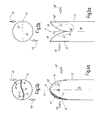
- Fig. 4a shows a section through a predetermined for example by the cylindrical segment 22 cyclone space 30 and the predetermined by contoured parts cyclone region 49.
- the corresponding wall parts 47, 47 ' are formed as well as the inflow openings 40, 40' a curved course following. In this way, the desired iso-kinetic flow behavior in the cyclone region 49 is set when passing through or entering the phase mixture with the inflow velocity 48, 48 '.
- Each of the wall contour 46 having inlet openings 40, 40 'and the wall parts 47, 47' abut at a center M, which lies on the axis of rotation R of the cyclone space 30, to each other.
- FIG. 4b illustrates that via diametrically, in other words point-symmetrically to the center M, arranged feeds (not shown) passes the phase mixture with the respective inflow velocity 48, 48 'from the inflow 28 through the respective inflow opening 40, 40' in the cyclone region 49 of the cyclone space 30.
- the concavely curved contour 46 of the molded parts 40, 40 ', 47, 47' effects the iso-kinetic flow behavior of the supplied phase mixture at least in the cyclone region 49 of the cyclone space 30.
- the presentation of the Fig. 5a and 5b is different from that of Fig. 4a and 4b in that the respective inflow opening 40, 40 'is straight, ie without curvature, and that the respective wall part 47, 47' is formed with the curved wall contour 46 is arranged inversely.
- the wall parts 47, 47 'meet at the center M which in the example shown is arranged at the height or axial position of the lower end of the symmetrically formed inflow openings 40, 40'. In this way, it is achieved that all fluid components of the phase mixture entering the respective inflow opening 40, 40 'are influenced by the respective wall part 47, 47' in the desired manner.
- FIG. 5a illustrates that in such an embodiment, the cyclone region 49 is toroidally formed and arranged around a radially inner free space 54.
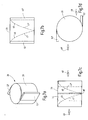
- FIG. 6a to 6d shown second embodiment of an inventively designed insert part 38 has a cone portion 50 and an annular connecting part 36.
- inner wall parts 47, 47' assigned to the cyclone space 30 and the cyclone area 59 as well as the outer wall parts 52, 52 'assigned to the inflow space 28 are formed on the insert part 38.
- the outer wall parts 52, 52 'formed like flanks on the outside of the cone part 50 of the insert part close, like the inner wall parts 47, 47', directly on the respective inflow opening 40, 40 'and in this respect give the inlet geometry for the respective inflow opening 40, 40 'flowing phase mixture before.
- the inner wall parts 47, 47 ', the outer wall parts 52, 52' and the inflow openings 40, 40 ', more precisely the front and surrounding edge regions, may be curved.
- the operation of the second embodiment corresponds to the representation of Fig. 4a and 4b ,
- a third embodiment of an inventively designed insert 38 is shown.
- the operation of the third embodiment corresponds to the representation of Fig. 5a and 5b , Accordingly, the outer wall parts 52, 52 'and the inflow openings 40, 40' each straight, ie formed without curvature, and only the arranged inside the cylinder part 39 inner wall parts 47, 47 'respectively formed and provided with the corresponding concave curved wall contour 46 ,
Landscapes
- Physics & Mathematics (AREA)
- Fluid Mechanics (AREA)
- Cyclones (AREA)
Applications Claiming Priority (1)
| Application Number | Priority Date | Filing Date | Title |
|---|---|---|---|
| DE102012018783.1A DE102012018783A1 (de) | 2012-09-22 | 2012-09-22 | Hydrozyklon |
Publications (2)
| Publication Number | Publication Date |
|---|---|
| EP2711082A2 true EP2711082A2 (fr) | 2014-03-26 |
| EP2711082A3 EP2711082A3 (fr) | 2018-03-28 |
Family
ID=49123630
Family Applications (1)
| Application Number | Title | Priority Date | Filing Date |
|---|---|---|---|
| EP13004254.2A Withdrawn EP2711082A3 (fr) | 2012-09-22 | 2013-08-29 | Hydrocyclone |
Country Status (2)
| Country | Link |
|---|---|
| EP (1) | EP2711082A3 (fr) |
| DE (1) | DE102012018783A1 (fr) |
Cited By (1)
| Publication number | Priority date | Publication date | Assignee | Title |
|---|---|---|---|---|
| CN113182086A (zh) * | 2021-05-19 | 2021-07-30 | 重庆工商大学 | 一种乳状液的破乳脱水分离方法 |
Citations (1)
| Publication number | Priority date | Publication date | Assignee | Title |
|---|---|---|---|---|
| GB2353236A (en) | 1999-08-17 | 2001-02-21 | Baker Hughes Ltd | Cyclone separator with multiple baffles of distinct pitch |
Family Cites Families (7)
| Publication number | Priority date | Publication date | Assignee | Title |
|---|---|---|---|---|
| US1960887A (en) * | 1931-09-24 | 1934-05-29 | Alexander William | Dust separator |
| FI56037C (fi) * | 1975-10-30 | 1979-11-12 | Enso Gutzeit Oy | Hydrocyklon |
| FR2382273A1 (fr) * | 1977-03-01 | 1978-09-29 | Frot Guy | Separateur centrifuge a vitesse de rotation initiale elevee et detente progressive |
| US4153558A (en) * | 1978-03-08 | 1979-05-08 | Ab Celleco | Hydrocyclone separator |
| CA1212648A (fr) * | 1981-02-14 | 1986-10-14 | John D. Peel | Cyclone separateur a decharge axiale descendante pour fractions legeres |
| GB9516381D0 (en) * | 1995-08-10 | 1995-10-11 | Vortoil Separation Systems Ltd | Hydrocyclone |
| GB9611692D0 (en) * | 1996-06-05 | 1996-08-07 | Kvaerner Process Systems As | Separating vessel |
-
2012
- 2012-09-22 DE DE102012018783.1A patent/DE102012018783A1/de not_active Ceased
-
2013
- 2013-08-29 EP EP13004254.2A patent/EP2711082A3/fr not_active Withdrawn
Patent Citations (1)
| Publication number | Priority date | Publication date | Assignee | Title |
|---|---|---|---|---|
| GB2353236A (en) | 1999-08-17 | 2001-02-21 | Baker Hughes Ltd | Cyclone separator with multiple baffles of distinct pitch |
Cited By (1)
| Publication number | Priority date | Publication date | Assignee | Title |
|---|---|---|---|---|
| CN113182086A (zh) * | 2021-05-19 | 2021-07-30 | 重庆工商大学 | 一种乳状液的破乳脱水分离方法 |
Also Published As
| Publication number | Publication date |
|---|---|
| EP2711082A3 (fr) | 2018-03-28 |
| DE102012018783A1 (de) | 2014-03-27 |
Similar Documents
| Publication | Publication Date | Title |
|---|---|---|
| DE60210817T2 (de) | Zyclonabscheider, Flüssigkeitssammelbehälter und Druckbehälter | |
| EP2471588B1 (fr) | Dispositif de séparation de liquides à partir de gaz | |
| EP2812121B1 (fr) | Hydrocyclone avec enrichissement des particules fines dans la partie d'evacuation des particules denses | |
| DE68920912T2 (de) | Wirbelrohr-Abscheider. | |
| EP3019276B1 (fr) | Broyeur agitateur à billes avec des canaux axials | |
| EP3132856B1 (fr) | Hydrocyclone à appauvrissement en matières fines dans le tamisat inférieur du cyclone | |
| DE19719555A1 (de) | Verfahren und Vorrichtung zum Ausscheiden von Gas aus gashaltigem Blut | |
| EP3661653B1 (fr) | Cyclone dépoussiéreur à courant continu | |
| DE102015008525A1 (de) | Fliehkraftabscheider und Filteranordnung | |
| DE4309920A1 (en) | Hydro-cyclone separator with central outlet tube for lighter fraction - which has internal guide vanes at a distance from end equal to half diameter of tube. | |
| EP3348804B1 (fr) | Réservoir de lubrifiant pour un système hydraulique | |
| DE3624086C2 (fr) | ||
| DE3936078C2 (de) | Drallerzeuger für Zyklonabscheider | |
| DE60308015T2 (de) | Vorrichtung und verfahren zur trennung eines gemisches | |
| DE68913882T2 (de) | Wirbelrohr-Abscheider. | |
| DE102009016045A1 (de) | Strömungsleitvorrichtung für ein Tauchrohr eines Zyklonabscheiders | |
| DE3623892A1 (de) | Verfahren und vorrichtung zur trennung der einzelnen phasen von mehrphasigen stroemenden medien | |
| DE3787656T2 (de) | Hydrozyklone. | |
| EP2711082A2 (fr) | Hydrocyclone | |
| EP0398864A2 (fr) | Procédé et dispositif de séparation de matières d'un milieu | |
| DE2532528A1 (de) | Verfahren zur einstellung eines vorbestimmten verteilungsgesetzes des durchflusses in einem stroemenden mediumsstrom sowie vorrichtung zur durchfuehrung des verfahrens | |
| DE102022104631B4 (de) | Gleichstromzyklonabscheider | |
| EP2692445A2 (fr) | Broyeur à billes à agitateur | |
| EP4243959B1 (fr) | Dispositif de séparation de particules d'un courant de gaz à l'aide d'une force centrifuge | |
| DE10230881A1 (de) | Wasserabscheider für Klimaanlagen |
Legal Events
| Date | Code | Title | Description |
|---|---|---|---|
| PUAI | Public reference made under article 153(3) epc to a published international application that has entered the european phase |
Free format text: ORIGINAL CODE: 0009012 |
|
| AK | Designated contracting states |
Kind code of ref document: A2 Designated state(s): AL AT BE BG CH CY CZ DE DK EE ES FI FR GB GR HR HU IE IS IT LI LT LU LV MC MK MT NL NO PL PT RO RS SE SI SK SM TR |
|
| AX | Request for extension of the european patent |
Extension state: BA ME |
|
| PUAL | Search report despatched |
Free format text: ORIGINAL CODE: 0009013 |
|
| AK | Designated contracting states |
Kind code of ref document: A3 Designated state(s): AL AT BE BG CH CY CZ DE DK EE ES FI FR GB GR HR HU IE IS IT LI LT LU LV MC MK MT NL NO PL PT RO RS SE SI SK SM TR |
|
| AX | Request for extension of the european patent |
Extension state: BA ME |
|
| RIC1 | Information provided on ipc code assigned before grant |
Ipc: B04C 5/04 20060101AFI20180217BHEP |
|
| STAA | Information on the status of an ep patent application or granted ep patent |
Free format text: STATUS: THE APPLICATION IS DEEMED TO BE WITHDRAWN |
|
| 18D | Application deemed to be withdrawn |
Effective date: 20180929 |