EP2711100B1 - Dispositif de positionnement d'empoises de laminoir - Google Patents
Dispositif de positionnement d'empoises de laminoir Download PDFInfo
- Publication number
- EP2711100B1 EP2711100B1 EP12786557.4A EP12786557A EP2711100B1 EP 2711100 B1 EP2711100 B1 EP 2711100B1 EP 12786557 A EP12786557 A EP 12786557A EP 2711100 B1 EP2711100 B1 EP 2711100B1
- Authority
- EP
- European Patent Office
- Prior art keywords
- rolling mill
- bearing chock
- face
- upright post
- positioning device
- Prior art date
- Legal status (The legal status is an assumption and is not a legal conclusion. Google has not performed a legal analysis and makes no representation as to the accuracy of the status listed.)
- Not-in-force
Links
- 238000005096 rolling process Methods 0.000 title claims description 72
- 239000000463 material Substances 0.000 claims description 7
- 238000006073 displacement reaction Methods 0.000 claims description 5
- 125000006850 spacer group Chemical group 0.000 claims description 3
- 230000000712 assembly Effects 0.000 description 4
- 238000000429 assembly Methods 0.000 description 4
- 238000005452 bending Methods 0.000 description 3
- 230000000694 effects Effects 0.000 description 3
- 230000007547 defect Effects 0.000 description 2
- 238000010586 diagram Methods 0.000 description 2
- 230000000717 retained effect Effects 0.000 description 2
- 229910000831 Steel Inorganic materials 0.000 description 1
- 239000002131 composite material Substances 0.000 description 1
- 238000010276 construction Methods 0.000 description 1
- 238000009434 installation Methods 0.000 description 1
- 238000000034 method Methods 0.000 description 1
- 239000010959 steel Substances 0.000 description 1
- 239000000758 substrate Substances 0.000 description 1
- 238000003466 welding Methods 0.000 description 1
Images


Classifications
-
- B—PERFORMING OPERATIONS; TRANSPORTING
- B21—MECHANICAL METAL-WORKING WITHOUT ESSENTIALLY REMOVING MATERIAL; PUNCHING METAL
- B21B—ROLLING OF METAL
- B21B31/00—Rolling stand structures; Mounting, adjusting, or interchanging rolls, roll mountings, or stand frames
- B21B31/16—Adjusting or positioning rolls
- B21B31/20—Adjusting or positioning rolls by moving rolls perpendicularly to roll axis
- B21B31/203—Balancing rolls
-
- B—PERFORMING OPERATIONS; TRANSPORTING
- B21—MECHANICAL METAL-WORKING WITHOUT ESSENTIALLY REMOVING MATERIAL; PUNCHING METAL
- B21B—ROLLING OF METAL
- B21B31/00—Rolling stand structures; Mounting, adjusting, or interchanging rolls, roll mountings, or stand frames
- B21B31/02—Rolling stand frames or housings; Roll mountings ; Roll chocks
Definitions
- the present invention relates to steel rolling equipment and, more particularly, relates to a rack structure of a rolling mill.
- the processing for wire and bar in the prior art mostly adopts rolling mill.
- the rolling mill can be generally categorized by its structure into sub-normal arch rack, cantilever rack or profile welding arch rack.
- the regulation and control for the spacing between rolls directly result in the size of the product to be rolled, and the precision of the size thereof depends on the overall rigidity of the rolling mill rack and the roller, the precision and selection of the roller.
- the rack type, sub-normal arch rack or cantilever rack taking the vertical installation of the arch rack as example, it is difficult to control as the deformation in both upward direction and downward direction is rather large.
- the lower bearing chock are fixed using components like bolts to the bottom seat of the sub-normal arch rack, and the press down mechanism of the upper bearing chock is usually provided on the upper portion of the crossbeam, so that during rolling, the upright post of the sub-normal arch rack located between the bottom seat and the upper crossbeam is subject to tension and has large elongation deformation throughout its entire length; as for the cantilever rack, the deformation of the upright post is basically similar. That is to say, if the rigidity of the rolling mill rack is not sufficient, with the deformation of other parts, the accumulated error would be large, and it is difficult to meet the precision requirements of the rolling.
- the preamble of claim 1 is based on EP0166478 and US 3938362 .
- the patent document named "Sheet rolling mill with hydraulic press down device on support roll” (publication number CN101658862A ) has disclosed a rolling mill rack comprising a lateral frame 10 located in the upper part, a lower rack beams 12-1 located in the lower part and an upright post 1 disposed therebetween.
- the overall structure can be seen as the sub-normal arch rack, wherein the upright posts during work will deform with elongation within the scope of its total length.
- the patent document named 'Composite rolling mill rack' (Publication number CN2796875Y ) has disclosed a rack including an upper crossbeam 1 and a lower crossbeams 4 and upright posts 2 connecting the upper crossbeam 1 and the lower crossbeam 4.
- the upper and lower crossbeams 1, 4 and the upright posts 2 are connected to each other by rods 8 the nuts 9, so that upright post 2 is subject to compressive stress.
- the defect residing in the structure is that the positioning between the upper and lower crossbeams 1, 4 and the upright posts 2 in the direction perpendicular to the upright post 2 cannot meet the requirements, because the upper and lower crossbeams 1, 4 and the upright posts 2 provide pressure to each other, and maintaining the position in the direction perpendicular to the upright posts 2 relies on the frictional force between each other, which is extremely unreliable; Further, due to the retaination from the structure itself that connects the rod 8 and nut 9, the pre-tightening force is very retained. Once the external force during the rolling process offset the pre-tightening force provided by the rod 8 and the nut 9, disengagements may occur between the upper and lower crossbeams 1, 4 and the upright posts 2 in serious cases, not to mention any precision of rolling.
- the Patent Document named 'the roller gap adjustment system for the base of the rolling mill without rack' has disclosed a structure including a left-handed threaded section 22a in the upper part, a cylindrical section 22b in the middle and a screw of a right-handed threaded section 22c in the lower part.
- the adjacent first and second bearing chock assemblies are connected to each other by a pair of screws 12 with identical construction, and the cylindrical section 22b in the middle of the screws 12 is fixed with respect to the frame member 28 along the axial direction and made as an shaft neck so as to rotate in the frame member 28 which itself is supported on the substrate 30.
- the left-handed thread section 22a in the upper part and the right-handed threaded section 22c in the lower part are connected, respectively, to the first and second bearing chock assemblies.
- the first and second bearing chock assemblies move to be close to or away from each other at the same time to achieve the adjustment of the roller gap.
- the screw 12 has elongation deformation along its entire length when under the tension, and thus the rigidity is low; the lower end of the screw 12 has a drooping shape, and when the second roller 14 on the second bearing chock assembly is subject to the impact load along the proceeding direction of the wire or bar during rolling, the lower end of the screw 12 also has bending deformation under pressure, resulting in the displacement of the operative position of the first and second roller, which seriously affects the rolling precision.
- the object of the present invention is to provide a rolling mill bearing chock positioning device, which can effectively positioning lower rolling mill bearing chock by exerting pre-tightening pressure.
- a rolling mill bearing chock positioning device comprises a first bearing chock assembly, an upright post and a rolling mill seat, characterized in that, a stepped face with downward panel is disposed on the lower middle portion of the upright post, and the stepped face and the upward-facing supporting face on the rolling mill base form therebetween a retaining mechanism for retaining the upward and downward movement of the bearing chock assembly by exerting pre-tightening pressure thereon.
- a stepped face with a downward panel is disposed on the lower middle portion of the upright post, and the space between the stepped face and the upward-facing supporting face on the rolling mill seat receives the bearing chock assembly. Due to the reliable connection between the lower end of the upright post and the rolling mill seat, the upright post is firstly stretched to be deformed first during assembly, i.e. the length between the stepped face and junctions of the lower end thereof and the rolling mill seat is properly stretched to be deformed therewith, which means the post body below the stepped face is in a stretched state and is pressed down by the stepped face onto the bearing chock assembly, wherein the pre-tightening pressure is determined by the amount of the deformation of the stretched upright post.
- the runout of the bearing chock assembly is avoided and the runout only occurs when the external force to the bearing chock assembly is larger than the pre-tightening force provided by the deformation of the stretched upright post.
- the invention can avoid the emergence of this situation successfully, because a proper pre-tightening tension can be provided by calculating reasonable stretched deformation amount according to the magnitude of the impact force during rolling, the selected material of the upright post and the cross-section thereof.
- the rolling precision not only depends on the roller's anti-deformation ability, i.e. rigidity, but also requires the rolling mill to have reliable rigidity, and the reliability of the fixing structure of the rack for the roller.
- the present invention has provided a novel and prominently effective scheme in the aspects of the rigid structure of the rack and the fixing structure of the rack for the roller. The present invention is further illustrated by the following specific embodiments.
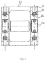
- a rolling mill bearing chock positioning device includes a first bearing chock assembly 30, an upright post 20 and a rolling mill seat 10.
- a downward-facing stepped face 21 is disposed on the lower middle portion of the upright post, and the stepped face 21 and the upward-facing supporting face on the rolling mill seat 10 form therebetween a position retaining mechanism for retaining upward and downward displacement of the bearing chock assembly (30) by exerting pre-tightening pressure thereon so as to position it.
- the upright post 20 is stretched during assembly, to enable the length between the stepped face 21 and the junction of the lower end thereof and the rolling mill seat 10 to be properly stretched so as to be deformed, and the body of the post below the stepped face 21 is in a stretched state and is pressed down by the stepped face 21 onto the bearing chock assembly 30.
- the pre-tightening pressure is determined by the amount of the stretched deformation of the upright post 20.
- the runout of the bearing chock assembly 30 only occurs when the external impact force to the bearing chock assembly 30 is larger than the pre-tightening force provided by the stretched deformation of the upright post 20.
- the present invention has provided proper tightening pressure exerted on the bearing chock assembly 30 along with the support effect from the rolling mill seat 10 to enable the bearing chock assembly 30 to be reliably fixed in position.
- the upper portion of the upright post 20 is a cylindrical threaded portion 22a
- the middle portion of the upright post 20 is a square post portion having square cross-section
- the lower portion 22c is below the square post portion 22b.
- the stepped face 21 is formed at the junction between the square post portion 22b and the lower portion 22c, and the panel of the stepped face 21 is horizontal or obliquely downward.
- the panel of the stepped face 21 is obliquely downward, so as to provide the maximum tightening pressure exerted on the bearing chock assembly 30 and also to facilitate the processing of the upright post 20.
- the lower portion 22c below the stepped face 21 of the upright post 20 has rod faces 23 parallel to each other, and the rod faces 23 are perpendicular to the axial direction of a roller.
- the lower portion 22c is located in a groove 11 with a top opening in the rolling mill seat 10, and the spacing between the two parallel rod faces 23 match the width of the groove 11.
- a hinged shaft 60 is arranged between the lower end of the lower portion 22c and the groove 11, and the hinged shaft 60 is parallel to the shaft core of the roller.
- the chamber area of the groove 11 is designed to ensure that the end part of the upright post 20 can be inserted therein, and meanwhile the required space is provided for the rotation of the upright post 20.
- the spacing between the two parallel rod faces 23 matching the width of the groove 11 is for the purpose of retaining the displacement of the upright post 20 in the axial direction of the roller, providing the positioning basis for the positioning of the first and second bearing chock assemblies 30, 40.
- a hole is provided on the end portion of the rod face 23 on the upright post 20, the hole and the hinged shaft 60 forms a hinge, and the hole is perpendicular to the plane of the rod face 23.
- a portion of post body below the stepped face 21 of the upright post 20 is located in the slot 31 provided on the bearing chock assembly 30, and they cooperate with each other to constitute a retaining mechanism which retains the movement of the first bearing chock assembly 30 along the axial direction of the roller.
- the stepped faces 21 are symmetrically arranged at the two sides of the rod face 23 with the centrosymmetric surface of the parallel rod faces 23, and the centrosymmetric surface of the rod face 23 is perpendicular to the axial direction of the roller, which ensures that the pressure exerted on the mouth of the slot 31 is uniform and symmetrical so as to prevent the upright post 20 from bending under the effect of bending moment.
- the end face of said first bearing assembly 30 is of an inverted convex shape, and the invented convex shape and the concave area provided on the rolling mill seat 10 constitute a retaining mechanism for retaining movement of the first bearing chock assembly 30 along the proceeding direction of the rolling material.
- the above structure realizes the displacement of the first bearing chock assembly 30 in the upward and downward, left and right, forward and backward directions, and the rotations in corresponding directions, so as to realize the reliable positioning of the first bearing chock assembly 30.
- the slot 31 is located at the front and rear sides of the chock body of the upper half of the bearing chock assembly 30 and passes through the upper and lower end faces of the upper half.
- the slot 31 has the opening pointing toward front and rear directions and the cross-section thereof is U-shaped.
- the walls of the slot 31 are parallel and the width of the slot matches the size of the post body below the stepped face 21 of the upright post 20 and located inside the slot in the axial direction of the roller so as to facilitate the engagement and disengagement of the upright post 20 and the slot 31.
- This is an example that the axial positioning of the first bearing chock assembly 30 is realized by the cooperation between the upright posts 20 and the first bearing chock assembly 30.
- the post body between the stepped face 25 and the stepped face 21 is a cylinder which is located inside the slot 31.
- the two cooperate with each other to constitute a retaining mechanism which retains the movement of the first bearing chock assembly 30 along the axial direction of the roller.
- This cooperation relationship can realize reliable positioning and facilitate assembling as well, i.e. facilitating smooth guiding of the upright post 20 into the slot 31 or removing out of the groove 31 during rotation of the upright post 20.
- the upper portion of the upright post 20 is a cylindrical threaded portion 22a, a cylindrical portion 22d is arranged between the cylindrical threaded portion 22a and the square post portion 22b, and the cylindrical portion 22d can be inserted into the hole on the upper crossbeam 50.
- the rolling mill rack comprises an upright post 20, a rolling mill seat 10 and an upper crossbeam 50.
- An end of the upright post 20 is connected with the rolling mill seat 10 through a hinged shaft 60.
- the other end of the upright post 20 passes through the upper crossbeam 50 and is locked by a nut 70 which optionally is a hydraulic nut so as to realize reliable connection strength and reduce the manpower labor intensity during assembly.
- the nut 70 can be firstly dismounted and moved away from the upper cross-beam 50, and then the upright post 20 is rotated to be disengaged and separated from one another. In that moment the space is created for the roller to be carried out or lifted out. After the roller is replaced, the upright post 20 is rotated to be in an engagement position with the roller, and then the upper crossbeam 50 is mounted and the nut 70 is screwed.
- a cylindrical portion 22e is provided between the stepped face 21 of the upright post 20 and the parallel rod faces 23.
- a stepped face 25 facing downwardly to the rear side of the rolling mill is formed between the upper ends of the rod faces 23 and the cylindrical portion 22e, and the angle between the stepped face 25 and the horizontal plane is in the range of 50 to 80 degrees, preferably, 60 degrees. The angle ensures the roller could be mount or dismounted.
- the stepped face 25 is arranged for retaining the opening degree of the upright post 20 during the rotation. As shown in Figs.
- the stepped face 25 contacts proper part of the rolling mill seat 10 when the upright post 20 is rotated to a proper position, and then the upright post 20 would be maintained at that opening position, where the upright post 20 disengages with the roller bearing chock assembly 30, so as to facilitate the dismounting and mounting procedure of the roller.
- the stepped face 25 faces downwardly to the outsides in the front and rear direction along the proceeding direction of the rolling material to be rolled in the rolling mill, that is to say, the stepped face 25 differs with the different positions of the upright posts 20, i.e. two of the four upright posts 20 are located at the feeding side of the roller, and the other two upright posts 20 are located at the discharge side of the roller; the stepped faces 25 of the two upright posts 20 at the feeding side of the roller face downwardly to the front of the feeding side of the roller, the stepped faces 25 of the two upright posts 20 at the discharge side of the roller face downwardly to the rear of the feeding side of the roller.
- the direction of the arrow is the proceeding direction of the rolling material to be rolled.
- a spacer block 80 is provided between the stepped face 21 and the bearing chock assembly 30 and/or between the bearing chock assembly 30 and the rolling mill seat 10.
- the bearing chock assembly 30 is positioned on the rolling mill seat 10 first conveniently, and then the upright post 20 is rotated to enable the post body on the middle and lower portion thereof to be located inside the slot 31.
- the stepped face 21 is higher than the upper end face of the bearing chock assembly 30 by a proper distance, so as to facilitating upright post 20 to rotate into position.
- the upright post 20 is stretched to deform properly and then a spacer block 80 with appropriate thickness is placed between the stepped face 21 and the upper end face of the bearing chock assembly 30 to ensure required amount of stretch of the upright post 20 to thereby ensure the pre-tightening tension.
- the external force for the stretched deformation of the upright post 20 can be provided by an oil cylinder, which is briefly described as follows.
- the oil cylinder 90 is provided between the second bearing chock assembly 40 and the upper crossbeam 50 to move downward to press down the second bearing chock assembly 40, which moves downward and contacts the first bearing chock assembly 30 and transmits the pressure to the rolling mill seat 10. Then, there is a tendency for the upper cross-beam 50 and the rolling mill seat 10 to be away from each other, which is restricted by the upright post 20, so that the upright post 20 is subject to tension and stretched and deforms. The amount of the stretched deformation is corresponding to working pressure of the oil cylinder 90, so that proper pre-tightening stretched deformation of the upright post 20 can be achieved so as to provide proper pre-tightening pressure to be exerted on the first bearing chock assembly 30.
- the present invention adopts the scheme with the lower portion of the upright post 20 exerting pre-tightening pressure on the first bearing chock assembly 30.
- the lower portion of the upright post 20 would no longer elongate, that is to say, the first bearing chock assembly 30 is reliably positioned.
- the post body of the upright post 20 above the stepped face 21 is stretched, the influence in the change of the spacing between the rollers is very retained, so that the rolling precision is largely improved. This provides a reliable foundation of assembly for the online adjustment and control to the spacing between the rollers of the rolling mill.
Landscapes
- Engineering & Computer Science (AREA)
- Mechanical Engineering (AREA)
- Rolling Contact Bearings (AREA)
- Rolls And Other Rotary Bodies (AREA)
Claims (10)
- Un dispositif de positionnement de cale de roulement d'un laminoir, comprenant un premier ensemble de cale de roulement (30), un montant vertical (20) et un siège de laminoir (10), caractérisé en ce que, une première face étagée (21) orientée vers le bas est disposée sur la partie moyenne inférieure du montant vertical (20), et la première face étagée (21) et une face d'appui du siège de laminoir (10) orientée vers le haut forment entre elles un mécanisme de retenue pour retenir le déplacement vers le haut et vers le bas du premier ensemble de cale de roulement (30) en exerçant une pression de serrage préalable sur celui-ci.
- Le dispositif de positionnement de cale de roulement d'un laminoir selon la revendication 1, caractérisé en ce que, la partie supérieure du montant vertical (20) est une partie cylindrique filetée (22a), la partie médiane du montant vertical (20) est une partie carrée de montant (22b) ayant une section transversale carrée, la partie inférieure (22c) est inférieure à la partie carrée de montant (22b), la première face étagée (21) est formée à la jonction entre la partie carrée de montant (22b) et le partie inférieure (22c), et le panneau de la première face étagée (21) est horizontal ou oblique vers le bas.
- Le dispositif de positionnement de cale de roulement d'un laminoir selon la revendication 1, caractérisé en ce que, le partie inférieure (22c) au-dessous de la première face étagée (21) du montant vertical (20) présente des faces de tige (23) parallèles les unes aux autres, les faces de tige (23) sont perpendiculaires à la direction axiale d'un rouleau, le partie inférieure (22c) est située dans une rainure (11) avec une ouverture supérieure dans le siège de laminoir (10), l'espacement entre les deux faces de tige (23) parallèles correspond à la largeur de la rainure (11), un arbre articulé est disposé entre l'extrémité inférieure de la partie inférieure (22c) et la rainure (11), et l'arbre articulé est parallèle au noyau d'arbre du rouleau.
- Le dispositif de positionnement de cale de roulement d'un laminoir selon la revendication 1, caractérisé en ce que, une portion du corps de montant entre la première face étagée (21) du montant vertical (20) est située dans une fente (31) prévue sur le premier ensemble de cale de roulement (30), les coopèrent entre eux pour constituer un mécanisme de retenue qui retient le mouvement du premier ensemble de cale de roulement (30) le long de la direction axiale du rouleau.
- Le dispositif de positionnement de cale de roulement d'un laminoir selon la revendication 1, caractérisé en ce que, la face d'extrémité dudit premier ensemble de roulement (30) est d'une forme convexe inversée, et avec la surface concave prévue sur le siège de laminoir (10), constituant un mécanisme de retenue pour retenir le mouvement du première ensemble de cale de roulement (30) au long de la direction de déroulement de la matière de laminage.
- Le dispositif de positionnement de cale de roulement d'un laminoir selon la revendication 1, caractérisé en ce que, le partie supérieure du montant vertical (20) est une partie cylindrique filetée (22a), une partie cylindrique (22d) est disposée entre la partie cylindrique filetée (22a) et la partie carrée de montant (22b), la partie cylindrique (22d) peut être insérée dans le trou sur une traverse supérieure (50), l'extrémité supérieure de la face de poste sur la partie carrée de montant (22b) sur la côté de décharge de la matière est prévue avec une face oblique (24) qui transite de la partie carrée de montant (22b) à la partie cylindrique (22d), et la face d'extrémité inférieure de la traverse supérieure (50) est prévue avec une face oblique (51) correspondant à la face oblique (24).
- Le dispositif de positionnement de cale de roulement d'un laminoir selon la revendication 1, caractérisé en ce que, une partie cylindrique (22e) est prévue entre la première face étagée (21) du montant vertical (20) et les faces parallèles de tige (23), une second face étagée (25) faisant face vers le bas sur la face arrière du laminoir est formée entre l'extrémité supérieure de la face de tige (23) et la partie cylindrique (22e), l'angle entre la deuxième face étagée (25) et le plan horizontal est dans la plage de 50 à 80 degrés, de préférence 60 degrés.
- Le dispositif de positionnement de cale de roulement d'un laminoir selon la revendication 1, caractérisé en ce que, un bloc d'espacement (80) est prévue entre la première face étagée (21) et le premier ensemble de cale de roulement (30) et/ou entre le premier ensemble de cale de roulement (30) et le siège de laminoir (10).
- Le dispositif de positionnement de cale de roulement d'un laminoir selon la revendication 4 or 5, caractérisé en ce que, le fente (31) est située au côté avant et arrière du corps de cale de la moitié supérieure du premier ensemble de cale de roulement (30) et passe à travers les faces d'extrémité inférieure et supérieure de la moitié supérieure, l'ouverture de la fente (31) pointe vers des directions avant et arrière et la section transversale de celle-ci est en forme du U, les parois de la fente (31) sont parallèles et la largeur de la fente correspond à la dimension du corps de montant au-dessous de la première face étagée (21) du montant vertical (20) et placée à l'intérieur de la fente dans la direction axiale du rouleau.
- Le dispositif de positionnement de cale de roulement d'un laminoir selon la revendication 7 or 9, caractérisé en ce que, le corps principal entre la deuxième face étagée (25) et la première face étagée (21) est un cylindre qui est située à l'intérieur de la fente (31).
Applications Claiming Priority (2)
| Application Number | Priority Date | Filing Date | Title |
|---|---|---|---|
| CN2011101312007A CN102303049B (zh) | 2011-05-18 | 2011-05-18 | 轧机轴承座的定位装置 |
| PCT/CN2012/075648 WO2012155851A1 (fr) | 2011-05-18 | 2012-05-17 | Dispositif de positionnement d'empoises de laminoir |
Publications (3)
| Publication Number | Publication Date |
|---|---|
| EP2711100A1 EP2711100A1 (fr) | 2014-03-26 |
| EP2711100A4 EP2711100A4 (fr) | 2015-01-28 |
| EP2711100B1 true EP2711100B1 (fr) | 2017-03-22 |
Family
ID=45377017
Family Applications (1)
| Application Number | Title | Priority Date | Filing Date |
|---|---|---|---|
| EP12786557.4A Not-in-force EP2711100B1 (fr) | 2011-05-18 | 2012-05-17 | Dispositif de positionnement d'empoises de laminoir |
Country Status (3)
| Country | Link |
|---|---|
| EP (1) | EP2711100B1 (fr) |
| CN (1) | CN102303049B (fr) |
| WO (1) | WO2012155851A1 (fr) |
Families Citing this family (7)
| Publication number | Priority date | Publication date | Assignee | Title |
|---|---|---|---|---|
| CN102303049B (zh) * | 2011-05-18 | 2013-11-13 | 合肥市百胜科技发展股份有限公司 | 轧机轴承座的定位装置 |
| CN104646430B (zh) * | 2015-01-23 | 2017-01-04 | 合肥市百胜科技发展股份有限公司 | 轧辊定位调整装置 |
| CN107782618B (zh) * | 2017-09-19 | 2019-12-31 | 中北大学 | 一种产品拉伸试验力学实验设备 |
| CN110421011B (zh) * | 2019-08-16 | 2024-07-05 | 中冶南方工程技术有限公司 | 用于18辊轧机侧支承装置的标定装置及标定方法 |
| CN117231634B (zh) * | 2023-10-24 | 2024-03-22 | 响水县瑞丰重型轴承座制造有限公司 | 一种具有缓冲机构的轴承座 |
| CN117755866A (zh) * | 2023-11-21 | 2024-03-26 | 无锡光群雷射科技有限公司 | 用于制备防镭射纸张上下翘曲的辊组件 |
| CN118372018A (zh) * | 2024-04-23 | 2024-07-23 | 上海电气上重碾磨特装设备有限公司 | 一种3500mm宽厚板轧机机架装配方法 |
Family Cites Families (14)
| Publication number | Priority date | Publication date | Assignee | Title |
|---|---|---|---|---|
| US3516276A (en) * | 1967-06-06 | 1970-06-23 | Davy & United Eng Co Ltd | Rolling mills |
| SE390608B (sv) * | 1973-02-12 | 1977-01-03 | Metalform Ab | Anordning for bearbetning av material genom valvsning eller pressning |
| IT1141791B (it) * | 1980-05-06 | 1986-10-08 | Danieli Off Mecc | Perfezionamenti alle gabbie a linea di laminazione fissa e gabbie a linea di laminazione fissa cosi' perfezionate |
| IT1174098B (it) * | 1984-05-28 | 1987-07-01 | Pomini Farrel Spa | Gabbia di laminazione del tipo a tiranti con supporti oscilanti con basi di appoggio intermedie |
| AU8164894A (en) | 1993-12-23 | 1995-07-27 | Morgan Construction Company | Parting adjustment system for housingless roll stand |
| DE19816320C1 (de) * | 1998-04-11 | 1999-11-25 | Schloemann Siemag Ag | Universalgerüst mit einem geteilten bedienungsseitgen Ständer |
| CN2796875Y (zh) | 2005-02-21 | 2006-07-19 | 郑红专 | 轧机组合机架 |
| CN201144089Y (zh) * | 2007-12-29 | 2008-11-05 | 中冶南方工程技术有限公司 | 一种移动式双层轧辊存放装置 |
| CN101428299B (zh) * | 2008-10-21 | 2011-01-12 | 北方工业大学 | 短应力线轧机 |
| CN201439095U (zh) * | 2009-07-07 | 2010-04-21 | 中冶赛迪工程技术股份有限公司 | 一种高刚度轧机机架 |
| CN101658862B (zh) | 2009-09-24 | 2010-08-04 | 朱勉学 | 支撑辊辊身带有液压压下装置的钢板轧机 |
| CN201768743U (zh) * | 2010-07-28 | 2011-03-23 | 德阳市西川机械技术研究所 | 预应力轧钢机机架 |
| CN102303049B (zh) * | 2011-05-18 | 2013-11-13 | 合肥市百胜科技发展股份有限公司 | 轧机轴承座的定位装置 |
| CN202207710U (zh) * | 2011-05-18 | 2012-05-02 | 合肥市百胜科技发展股份有限公司 | 轧机轴承座的定位装置 |
-
2011
- 2011-05-18 CN CN2011101312007A patent/CN102303049B/zh active Active
-
2012
- 2012-05-17 EP EP12786557.4A patent/EP2711100B1/fr not_active Not-in-force
- 2012-05-17 WO PCT/CN2012/075648 patent/WO2012155851A1/fr not_active Ceased
Also Published As
| Publication number | Publication date |
|---|---|
| EP2711100A1 (fr) | 2014-03-26 |
| WO2012155851A1 (fr) | 2012-11-22 |
| EP2711100A4 (fr) | 2015-01-28 |
| CN102303049A (zh) | 2012-01-04 |
| CN102303049B (zh) | 2013-11-13 |
Similar Documents
| Publication | Publication Date | Title |
|---|---|---|
| EP2711100A1 (fr) | Dispositif de positionnement d'empoises de laminoir | |
| CN104668290A (zh) | 轧机 | |
| WO2012155855A1 (fr) | Laminoir intelligent | |
| CN102632077A (zh) | 全预应力高刚度万能轧机 | |
| WO2012155854A1 (fr) | Laminoir | |
| JP2020518455A (ja) | 金属製品を案内する装置及び方法 | |
| US8365566B2 (en) | Device for adjusting the distance of a stripper chisel | |
| WO2009113413A1 (fr) | Laminoir de tôle forte et procédé de laminage de tôle forte | |
| CN204583860U (zh) | 轧机 | |
| CN202516841U (zh) | 全预应力高刚度万能轧机 | |
| CN201168722Y (zh) | 组装式二辊轧机 | |
| CN101249514A (zh) | 组装式二辊轧机 | |
| CN209829876U (zh) | 一种平面调整工作辊装置及包括其的轧机 | |
| CN101541445B (zh) | 轧机机座 | |
| CN201940518U (zh) | 轧球辊可快速装卸的轧钢球机的成球机构 | |
| JP6106481B2 (ja) | 冷間ロール成形機及び冷間ロール成形法 | |
| CN1194824C (zh) | 二维控制挠曲度的轧机 | |
| CN212682247U (zh) | 一种卷材导向装置 | |
| CN100355512C (zh) | 轧机机座和调整轧机机座的方法 | |
| WO2012155853A1 (fr) | Cadre de laminoir | |
| RU2567141C2 (ru) | Подающий узел прокатного стана и способ его настройки | |
| CN111215450B (zh) | 一种大开口式整体机架多辊轧机 | |
| CN210730625U (zh) | 一种冷弯机用导向结构 | |
| CN202123106U (zh) | 轧机机架 | |
| RU2297890C1 (ru) | Рабочая клеть стана холодной прокатки труб |
Legal Events
| Date | Code | Title | Description |
|---|---|---|---|
| PUAI | Public reference made under article 153(3) epc to a published international application that has entered the european phase |
Free format text: ORIGINAL CODE: 0009012 |
|
| 17P | Request for examination filed |
Effective date: 20131217 |
|
| AK | Designated contracting states |
Kind code of ref document: A1 Designated state(s): AL AT BE BG CH CY CZ DE DK EE ES FI FR GB GR HR HU IE IS IT LI LT LU LV MC MK MT NL NO PL PT RO RS SE SI SK SM TR |
|
| DAX | Request for extension of the european patent (deleted) | ||
| A4 | Supplementary search report drawn up and despatched |
Effective date: 20150108 |
|
| RIC1 | Information provided on ipc code assigned before grant |
Ipc: B21B 31/32 20060101ALI20141222BHEP Ipc: B21B 31/16 20060101AFI20141222BHEP |
|
| GRAP | Despatch of communication of intention to grant a patent |
Free format text: ORIGINAL CODE: EPIDOSNIGR1 |
|
| INTG | Intention to grant announced |
Effective date: 20160729 |
|
| GRAS | Grant fee paid |
Free format text: ORIGINAL CODE: EPIDOSNIGR3 |
|
| GRAA | (expected) grant |
Free format text: ORIGINAL CODE: 0009210 |
|
| AK | Designated contracting states |
Kind code of ref document: B1 Designated state(s): AL AT BE BG CH CY CZ DE DK EE ES FI FR GB GR HR HU IE IS IT LI LT LU LV MC MK MT NL NO PL PT RO RS SE SI SK SM TR |
|
| REG | Reference to a national code |
Ref country code: GB Ref legal event code: FG4D |
|
| REG | Reference to a national code |
Ref country code: CH Ref legal event code: EP |
|
| REG | Reference to a national code |
Ref country code: AT Ref legal event code: REF Ref document number: 877195 Country of ref document: AT Kind code of ref document: T Effective date: 20170415 |
|
| REG | Reference to a national code |
Ref country code: IE Ref legal event code: FG4D |
|
| REG | Reference to a national code |
Ref country code: DE Ref legal event code: R096 Ref document number: 602012030198 Country of ref document: DE |
|
| REG | Reference to a national code |
Ref country code: NL Ref legal event code: MP Effective date: 20170322 |
|
| PG25 | Lapsed in a contracting state [announced via postgrant information from national office to epo] |
Ref country code: NO Free format text: LAPSE BECAUSE OF FAILURE TO SUBMIT A TRANSLATION OF THE DESCRIPTION OR TO PAY THE FEE WITHIN THE PRESCRIBED TIME-LIMIT Effective date: 20170622 Ref country code: FI Free format text: LAPSE BECAUSE OF FAILURE TO SUBMIT A TRANSLATION OF THE DESCRIPTION OR TO PAY THE FEE WITHIN THE PRESCRIBED TIME-LIMIT Effective date: 20170322 Ref country code: HR Free format text: LAPSE BECAUSE OF FAILURE TO SUBMIT A TRANSLATION OF THE DESCRIPTION OR TO PAY THE FEE WITHIN THE PRESCRIBED TIME-LIMIT Effective date: 20170322 Ref country code: GR Free format text: LAPSE BECAUSE OF FAILURE TO SUBMIT A TRANSLATION OF THE DESCRIPTION OR TO PAY THE FEE WITHIN THE PRESCRIBED TIME-LIMIT Effective date: 20170623 Ref country code: LT Free format text: LAPSE BECAUSE OF FAILURE TO SUBMIT A TRANSLATION OF THE DESCRIPTION OR TO PAY THE FEE WITHIN THE PRESCRIBED TIME-LIMIT Effective date: 20170322 |
|
| REG | Reference to a national code |
Ref country code: LT Ref legal event code: MG4D |
|
| REG | Reference to a national code |
Ref country code: AT Ref legal event code: MK05 Ref document number: 877195 Country of ref document: AT Kind code of ref document: T Effective date: 20170322 |
|
| PG25 | Lapsed in a contracting state [announced via postgrant information from national office to epo] |
Ref country code: BG Free format text: LAPSE BECAUSE OF FAILURE TO SUBMIT A TRANSLATION OF THE DESCRIPTION OR TO PAY THE FEE WITHIN THE PRESCRIBED TIME-LIMIT Effective date: 20170622 Ref country code: LV Free format text: LAPSE BECAUSE OF FAILURE TO SUBMIT A TRANSLATION OF THE DESCRIPTION OR TO PAY THE FEE WITHIN THE PRESCRIBED TIME-LIMIT Effective date: 20170322 Ref country code: LU Free format text: LAPSE BECAUSE OF NON-PAYMENT OF DUE FEES Effective date: 20170531 Ref country code: SE Free format text: LAPSE BECAUSE OF FAILURE TO SUBMIT A TRANSLATION OF THE DESCRIPTION OR TO PAY THE FEE WITHIN THE PRESCRIBED TIME-LIMIT Effective date: 20170322 Ref country code: RS Free format text: LAPSE BECAUSE OF FAILURE TO SUBMIT A TRANSLATION OF THE DESCRIPTION OR TO PAY THE FEE WITHIN THE PRESCRIBED TIME-LIMIT Effective date: 20170322 |
|
| PG25 | Lapsed in a contracting state [announced via postgrant information from national office to epo] |
Ref country code: NL Free format text: LAPSE BECAUSE OF FAILURE TO SUBMIT A TRANSLATION OF THE DESCRIPTION OR TO PAY THE FEE WITHIN THE PRESCRIBED TIME-LIMIT Effective date: 20170322 |
|
| PG25 | Lapsed in a contracting state [announced via postgrant information from national office to epo] |
Ref country code: CZ Free format text: LAPSE BECAUSE OF FAILURE TO SUBMIT A TRANSLATION OF THE DESCRIPTION OR TO PAY THE FEE WITHIN THE PRESCRIBED TIME-LIMIT Effective date: 20170322 Ref country code: EE Free format text: LAPSE BECAUSE OF FAILURE TO SUBMIT A TRANSLATION OF THE DESCRIPTION OR TO PAY THE FEE WITHIN THE PRESCRIBED TIME-LIMIT Effective date: 20170322 Ref country code: ES Free format text: LAPSE BECAUSE OF FAILURE TO SUBMIT A TRANSLATION OF THE DESCRIPTION OR TO PAY THE FEE WITHIN THE PRESCRIBED TIME-LIMIT Effective date: 20170322 Ref country code: IT Free format text: LAPSE BECAUSE OF FAILURE TO SUBMIT A TRANSLATION OF THE DESCRIPTION OR TO PAY THE FEE WITHIN THE PRESCRIBED TIME-LIMIT Effective date: 20170322 Ref country code: SK Free format text: LAPSE BECAUSE OF FAILURE TO SUBMIT A TRANSLATION OF THE DESCRIPTION OR TO PAY THE FEE WITHIN THE PRESCRIBED TIME-LIMIT Effective date: 20170322 Ref country code: AT Free format text: LAPSE BECAUSE OF FAILURE TO SUBMIT A TRANSLATION OF THE DESCRIPTION OR TO PAY THE FEE WITHIN THE PRESCRIBED TIME-LIMIT Effective date: 20170322 Ref country code: RO Free format text: LAPSE BECAUSE OF FAILURE TO SUBMIT A TRANSLATION OF THE DESCRIPTION OR TO PAY THE FEE WITHIN THE PRESCRIBED TIME-LIMIT Effective date: 20170322 |
|
| PG25 | Lapsed in a contracting state [announced via postgrant information from national office to epo] |
Ref country code: SM Free format text: LAPSE BECAUSE OF FAILURE TO SUBMIT A TRANSLATION OF THE DESCRIPTION OR TO PAY THE FEE WITHIN THE PRESCRIBED TIME-LIMIT Effective date: 20170322 Ref country code: IS Free format text: LAPSE BECAUSE OF FAILURE TO SUBMIT A TRANSLATION OF THE DESCRIPTION OR TO PAY THE FEE WITHIN THE PRESCRIBED TIME-LIMIT Effective date: 20170722 Ref country code: PT Free format text: LAPSE BECAUSE OF FAILURE TO SUBMIT A TRANSLATION OF THE DESCRIPTION OR TO PAY THE FEE WITHIN THE PRESCRIBED TIME-LIMIT Effective date: 20170724 Ref country code: PL Free format text: LAPSE BECAUSE OF FAILURE TO SUBMIT A TRANSLATION OF THE DESCRIPTION OR TO PAY THE FEE WITHIN THE PRESCRIBED TIME-LIMIT Effective date: 20170322 |
|
| REG | Reference to a national code |
Ref country code: DE Ref legal event code: R119 Ref document number: 602012030198 Country of ref document: DE |
|
| REG | Reference to a national code |
Ref country code: CH Ref legal event code: PL |
|
| PLBE | No opposition filed within time limit |
Free format text: ORIGINAL CODE: 0009261 |
|
| STAA | Information on the status of an ep patent application or granted ep patent |
Free format text: STATUS: NO OPPOSITION FILED WITHIN TIME LIMIT |
|
| PG25 | Lapsed in a contracting state [announced via postgrant information from national office to epo] |
Ref country code: MC Free format text: LAPSE BECAUSE OF FAILURE TO SUBMIT A TRANSLATION OF THE DESCRIPTION OR TO PAY THE FEE WITHIN THE PRESCRIBED TIME-LIMIT Effective date: 20170322 Ref country code: DK Free format text: LAPSE BECAUSE OF FAILURE TO SUBMIT A TRANSLATION OF THE DESCRIPTION OR TO PAY THE FEE WITHIN THE PRESCRIBED TIME-LIMIT Effective date: 20170322 |
|
| REG | Reference to a national code |
Ref country code: IE Ref legal event code: MM4A |
|
| 26N | No opposition filed |
Effective date: 20180102 |
|
| GBPC | Gb: european patent ceased through non-payment of renewal fee |
Effective date: 20170622 |
|
| PG25 | Lapsed in a contracting state [announced via postgrant information from national office to epo] |
Ref country code: SI Free format text: LAPSE BECAUSE OF FAILURE TO SUBMIT A TRANSLATION OF THE DESCRIPTION OR TO PAY THE FEE WITHIN THE PRESCRIBED TIME-LIMIT Effective date: 20170322 Ref country code: CH Free format text: LAPSE BECAUSE OF NON-PAYMENT OF DUE FEES Effective date: 20170531 Ref country code: LI Free format text: LAPSE BECAUSE OF NON-PAYMENT OF DUE FEES Effective date: 20170531 |
|
| REG | Reference to a national code |
Ref country code: FR Ref legal event code: ST Effective date: 20180131 |
|
| PG25 | Lapsed in a contracting state [announced via postgrant information from national office to epo] |
Ref country code: LU Free format text: LAPSE BECAUSE OF NON-PAYMENT OF DUE FEES Effective date: 20170517 |
|
| REG | Reference to a national code |
Ref country code: BE Ref legal event code: MM Effective date: 20170531 |
|
| PG25 | Lapsed in a contracting state [announced via postgrant information from national office to epo] |
Ref country code: GB Free format text: LAPSE BECAUSE OF NON-PAYMENT OF DUE FEES Effective date: 20170622 Ref country code: DE Free format text: LAPSE BECAUSE OF NON-PAYMENT OF DUE FEES Effective date: 20171201 Ref country code: IE Free format text: LAPSE BECAUSE OF NON-PAYMENT OF DUE FEES Effective date: 20170517 |
|
| PG25 | Lapsed in a contracting state [announced via postgrant information from national office to epo] |
Ref country code: FR Free format text: LAPSE BECAUSE OF NON-PAYMENT OF DUE FEES Effective date: 20170531 |
|
| PG25 | Lapsed in a contracting state [announced via postgrant information from national office to epo] |
Ref country code: BE Free format text: LAPSE BECAUSE OF NON-PAYMENT OF DUE FEES Effective date: 20170531 |
|
| PG25 | Lapsed in a contracting state [announced via postgrant information from national office to epo] |
Ref country code: MT Free format text: LAPSE BECAUSE OF NON-PAYMENT OF DUE FEES Effective date: 20170517 |
|
| PG25 | Lapsed in a contracting state [announced via postgrant information from national office to epo] |
Ref country code: HU Free format text: LAPSE BECAUSE OF FAILURE TO SUBMIT A TRANSLATION OF THE DESCRIPTION OR TO PAY THE FEE WITHIN THE PRESCRIBED TIME-LIMIT; INVALID AB INITIO Effective date: 20120517 |
|
| PG25 | Lapsed in a contracting state [announced via postgrant information from national office to epo] |
Ref country code: CY Free format text: LAPSE BECAUSE OF NON-PAYMENT OF DUE FEES Effective date: 20170322 |
|
| PG25 | Lapsed in a contracting state [announced via postgrant information from national office to epo] |
Ref country code: MK Free format text: LAPSE BECAUSE OF FAILURE TO SUBMIT A TRANSLATION OF THE DESCRIPTION OR TO PAY THE FEE WITHIN THE PRESCRIBED TIME-LIMIT Effective date: 20170322 |
|
| PG25 | Lapsed in a contracting state [announced via postgrant information from national office to epo] |
Ref country code: TR Free format text: LAPSE BECAUSE OF FAILURE TO SUBMIT A TRANSLATION OF THE DESCRIPTION OR TO PAY THE FEE WITHIN THE PRESCRIBED TIME-LIMIT Effective date: 20170322 |
|
| PG25 | Lapsed in a contracting state [announced via postgrant information from national office to epo] |
Ref country code: AL Free format text: LAPSE BECAUSE OF FAILURE TO SUBMIT A TRANSLATION OF THE DESCRIPTION OR TO PAY THE FEE WITHIN THE PRESCRIBED TIME-LIMIT Effective date: 20170322 |