EP2711212B1 - Dispositif de suspension pour véhicule - Google Patents
Dispositif de suspension pour véhicule Download PDFInfo
- Publication number
- EP2711212B1 EP2711212B1 EP12838999.6A EP12838999A EP2711212B1 EP 2711212 B1 EP2711212 B1 EP 2711212B1 EP 12838999 A EP12838999 A EP 12838999A EP 2711212 B1 EP2711212 B1 EP 2711212B1
- Authority
- EP
- European Patent Office
- Prior art keywords
- screw
- vehicle
- pair
- worm
- suspension
- Prior art date
- Legal status (The legal status is an assumption and is not a legal conclusion. Google has not performed a legal analysis and makes no representation as to the accuracy of the status listed.)
- Not-in-force
Links
- 239000000725 suspension Substances 0.000 title claims description 44
- 230000007246 mechanism Effects 0.000 claims description 27
- 239000003638 chemical reducing agent Substances 0.000 claims description 7
- 229920003002 synthetic resin Polymers 0.000 claims description 7
- 239000000057 synthetic resin Substances 0.000 claims description 7
- 238000006073 displacement reaction Methods 0.000 claims description 4
- 238000010276 construction Methods 0.000 description 30
- 239000004696 Poly ether ether ketone Substances 0.000 description 4
- 238000009434 installation Methods 0.000 description 4
- 229920002530 polyetherether ketone Polymers 0.000 description 4
- XEEYBQQBJWHFJM-UHFFFAOYSA-N Iron Chemical compound [Fe] XEEYBQQBJWHFJM-UHFFFAOYSA-N 0.000 description 2
- 229920002302 Nylon 6,6 Polymers 0.000 description 2
- 229930182556 Polyacetal Natural products 0.000 description 2
- 239000004734 Polyphenylene sulfide Substances 0.000 description 2
- 239000006096 absorbing agent Substances 0.000 description 2
- 230000000694 effects Effects 0.000 description 2
- 238000001746 injection moulding Methods 0.000 description 2
- 229920006324 polyoxymethylene Polymers 0.000 description 2
- 229920000069 polyphenylene sulfide Polymers 0.000 description 2
- 230000035939 shock Effects 0.000 description 2
- 238000004088 simulation Methods 0.000 description 2
- 229910000838 Al alloy Inorganic materials 0.000 description 1
- 229920000049 Carbon (fiber) Polymers 0.000 description 1
- 229910000861 Mg alloy Inorganic materials 0.000 description 1
- 239000004677 Nylon Substances 0.000 description 1
- 229910045601 alloy Inorganic materials 0.000 description 1
- 239000000956 alloy Substances 0.000 description 1
- 239000004917 carbon fiber Substances 0.000 description 1
- 230000001276 controlling effect Effects 0.000 description 1
- 230000005611 electricity Effects 0.000 description 1
- 238000005516 engineering process Methods 0.000 description 1
- 239000003365 glass fiber Substances 0.000 description 1
- 239000010720 hydraulic oil Substances 0.000 description 1
- 229910052742 iron Inorganic materials 0.000 description 1
- 239000000463 material Substances 0.000 description 1
- 238000005259 measurement Methods 0.000 description 1
- 229910052751 metal Inorganic materials 0.000 description 1
- 239000002184 metal Substances 0.000 description 1
- 238000000034 method Methods 0.000 description 1
- 229920001778 nylon Polymers 0.000 description 1
- 229920006122 polyamide resin Polymers 0.000 description 1
- 230000001105 regulatory effect Effects 0.000 description 1
- 239000010935 stainless steel Substances 0.000 description 1
- 229910001220 stainless steel Inorganic materials 0.000 description 1
- XLYOFNOQVPJJNP-UHFFFAOYSA-N water Substances O XLYOFNOQVPJJNP-UHFFFAOYSA-N 0.000 description 1
Images



Classifications
-
- B—PERFORMING OPERATIONS; TRANSPORTING
- B60—VEHICLES IN GENERAL
- B60G—VEHICLE SUSPENSION ARRANGEMENTS
- B60G7/00—Pivoted suspension arms; Accessories thereof
- B60G7/006—Attaching arms to sprung or unsprung part of vehicle, characterised by comprising attachment means controlled by an external actuator, e.g. a fluid or electrical motor
-
- B—PERFORMING OPERATIONS; TRANSPORTING
- B60—VEHICLES IN GENERAL
- B60G—VEHICLE SUSPENSION ARRANGEMENTS
- B60G17/00—Resilient suspensions having means for adjusting the spring or vibration-damper characteristics, for regulating the distance between a supporting surface and a sprung part of vehicle or for locking suspension during use to meet varying vehicular or surface conditions, e.g. due to speed or load
- B60G17/015—Resilient suspensions having means for adjusting the spring or vibration-damper characteristics, for regulating the distance between a supporting surface and a sprung part of vehicle or for locking suspension during use to meet varying vehicular or surface conditions, e.g. due to speed or load the regulating means comprising electric or electronic elements
- B60G17/016—Resilient suspensions having means for adjusting the spring or vibration-damper characteristics, for regulating the distance between a supporting surface and a sprung part of vehicle or for locking suspension during use to meet varying vehicular or surface conditions, e.g. due to speed or load the regulating means comprising electric or electronic elements characterised by their responsiveness, when the vehicle is travelling, to specific motion, a specific condition, or driver input
- B60G17/0162—Resilient suspensions having means for adjusting the spring or vibration-damper characteristics, for regulating the distance between a supporting surface and a sprung part of vehicle or for locking suspension during use to meet varying vehicular or surface conditions, e.g. due to speed or load the regulating means comprising electric or electronic elements characterised by their responsiveness, when the vehicle is travelling, to specific motion, a specific condition, or driver input mainly during a motion involving steering operation, e.g. cornering, overtaking
-
- B—PERFORMING OPERATIONS; TRANSPORTING
- B60—VEHICLES IN GENERAL
- B60G—VEHICLE SUSPENSION ARRANGEMENTS
- B60G2200/00—Indexing codes relating to suspension types
- B60G2200/40—Indexing codes relating to the wheels in the suspensions
- B60G2200/46—Indexing codes relating to the wheels in the suspensions camber angle
-
- B—PERFORMING OPERATIONS; TRANSPORTING
- B60—VEHICLES IN GENERAL
- B60G—VEHICLE SUSPENSION ARRANGEMENTS
- B60G2202/00—Indexing codes relating to the type of spring, damper or actuator
- B60G2202/40—Type of actuator
-
- B—PERFORMING OPERATIONS; TRANSPORTING
- B60—VEHICLES IN GENERAL
- B60G—VEHICLE SUSPENSION ARRANGEMENTS
- B60G2202/00—Indexing codes relating to the type of spring, damper or actuator
- B60G2202/40—Type of actuator
- B60G2202/442—Rotary actuator
-
- B—PERFORMING OPERATIONS; TRANSPORTING
- B60—VEHICLES IN GENERAL
- B60G—VEHICLE SUSPENSION ARRANGEMENTS
- B60G2204/00—Indexing codes related to suspensions per se or to auxiliary parts
- B60G2204/10—Mounting of suspension elements
- B60G2204/14—Mounting of suspension arms
- B60G2204/143—Mounting of suspension arms on the vehicle body or chassis
Definitions
- the present invention relates to a double wishbone suspension for a vehicle that can suitably change the camber angle according to the traveling condition of the vehicle.
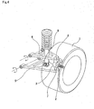
- FIG. 4 illustrates a first example of conventional construction of a double wishbone suspension that is disclosed in " Illustrated Book of Car Mechanisms and Structures" (Hosokawa, Takeshi; Grand Prix Book Publishing Co., Ltd.; January 10, 2003; pg. 207 ).
- the upper arm 4 is made using a so-called A-frame having an A shape, with the tip end section (when installed in the vehicle, the end section on the outside in the width direction of the vehicle, or the end section on the right side in FIG. 4 ) thereof being connected to the top end section of the knuckle 3 by way of an upper ball joint 6.
- the base end section of the upper arm 4 (when installed in the vehicle, the end section on the center side in the width direction of the vehicle, or the end section on the left side in FIG. 4 ) is supported by the vehicle (not illustrated in the figure) by a pivot shaft so as to be able to pivot.
- the lower arm 5 is also made using so-called A-frame having an A shape, with the tip end section thereof being connected to the bottom end section of the knuckle 3 by way of a lower ball joint 7.
- the base end section of the lower arm 5 is supported by the vehicle (not illustrated in the figure) by a pivot shaft so as to be able to pivot.
- the lower arm 5 supports the bottom end section of a shock absorber 8, the top end of which is fastened to the vehicle, by a pivot shaft so as to be able to pivot.
- the camber angle is preset to a specified angle.
- the camber angle that is preset in this way cannot be changed according to the traveling conditions of the vehicle.
- the turning movement of a vehicle occurs due to the difference in drive force on the left and right wheels and the like, however mainly occurs due to lateral force on the tires.
- This lateral force on the tires is generated by the driver operating the steering wheel and causing the toe angle (steering angle) of the front wheels to change by way of a steering gear, and causing a shift (slip angle) to occur between the traveling direction of the vehicle and the direction of the tires.
- This lateral force on the tires in addition to the toe angle, is known to be affected by the change in the camber angle.
- FIG. 5 illustrates the relationship between the lateral force on the tires and the slip angle when the camber angle, which was found by the inventors through simulation, was used as a parameter. As can be clearly seen in FIG.
- JP 10-264636 (A ) discloses a double wishbone suspension for a vehicle that is capable of changing the camber angle according to the traveling condition of the vehicle.
- FIG. 6 illustrates a second example of conventional construction as disclosed in this patent literature.
- hydraulic cylinders 9 and 10 which are capable of expanding and contracting, are provided in the middle section of the upper arm 4a and lower arm 5a and make it possible for the entire length of upper arm 4a and the lower arm 5a to change.
- a sensor detects the angle of sideslip of the wheel 1, and when it is recognized that the camber angle must be changed, a specified amount of hydraulic oil is supplied to the hydraulic cylinders 9 and 10 from a hydraulic pump that is located in the engine room by way of hydraulic piping and various valves. As a result, the entire lengths of the upper arm 4a and the lower arm 5a are changed and the camber angle of the wheel 1 is changed. With the suspension of this second example of convention construction, it is possible to adjust the size of the lateral force on the tires, and improve the turning performance of the vehicle, as well as the performance for traveling straight.
- JP 2009-107533 (A ) and JP 2010-83212 (A ) disclose camber angle adjustment apparatuses for changing the size of the camber angle according to the traveling conditions of the vehicle.
- JP 10-263636 (A ) there is a problem in that the construction for making it possible to change the camber angle is complex, and invites an increase in size and weight of the suspension.
- a load measurement apparatus for measure a load applied to a bearing unit that is disclosed in JP 2005-98771 (A ).
- JP 52 08 89 20 discloses also an adjustable track device.
- the object of the present invention is to achieve simple construction of suspension for a vehicle that is capable of suitably changing the camber angle according to the traveling condition of the vehicle without inviting complexity of the apparatus and also the increase in size and weight that accompanies such a complex apparatus.
- the suspension for a vehicle of the present invention basically is the same as a double wishbone suspension for a vehicle having conventional construction, and comprises: an upper arm that has a tip end section that is connected by way of an upper joint to the upper portion of a knuckle by which a wheel is supported so as to be able to rotate, and a base end section that is supported by the vehicle so as to be able to pivot in the up-down direction; and a lower arm that has a tip end section that is connected by way of a lower joint to the lower portion of the knuckle, and a base end section that is supported by the vehicle so as to be able to pivot in the up-down direction.
- the suspension for a vehicle of the present invention is characterized by the construction of the upper arm.
- the upper arm of the suspension for a vehicle of the present invention comprises:
- the suspension for an automobile of the present invention is characterized in that by the electric motor rotating and driving the worm so as to cause the pair of screw shafts to move out in opposite directions from each other in the axial direction, the opening angle of the pair of link arms changes, and thus the length of the pair of link arms in the width direction of the vehicle changes, or in other words, the overall length of the upper arm in the width direction of the vehicle changes.
- a feed screw mechanism By respectively combining the pair of screw shafts and the pair of screw nuts, a feed screw mechanism is formed.
- a sliding screw type feed screw mechanism can be applied as this feed screw mechanism, wherein the pair of screw shafts and the pair of screw nuts are respectively combined, and a female screw thread that is formed around the inner circumferential surface of each of the screw nuts engage with a male screw thread that is formed around the outer circumferential surface of each of the screw shafts such that they can slide against one another.
- a ball screw type feed screw mechanism can be applied as this feed screw mechanism, wherein the pair of screw shafts and the pair of screw nuts are respectively combined, and an outer-diameter side ball screw groove that is formed around the inner circumferential surface of each of the screw nuts engage with an inner-diameter side ball screw groove that is formed around the outer circumferential surface of each of the screw shafts by way of a plurality of balls that are placed between them.
- a rotation stopping mechanism for preventing relative rotation of the screw shafts with respect to the casing while allowing axial displacement of the screw shafts is provided between the pair of screw shafts and the casing.
- the worm wheel is made of synthetic resin. Furthermore, preferably, a speed reducer that increases the power of the electric motor and transmits that power to the worm is provided between the worm and the electric motor.
- the present invention constructed as described above, it is possible to achieve a suspension for a vehicle with simple construction that is capable of suitably changing the camber angle according to the traveling conditions of the vehicle, and it is possible to make the overall suspension more compact and lightweight.
- construction for making it possible to change the overall length of the upper arm is consolidated in the upper arm itself. Therefore, the other members, such as the lower arm, can be the same as used in the conventional construction.
- the upper arm is such that by using simple construction of just combining a pair of feed screw mechanisms, a worm reduction gear and a link mechanism, it becomes possible to change the overall length of the upper arm.
- control of the camber angle (control of the overall length of the upper arm) is performed controlling the supply of electricity to an electric motor, so when compared to being controlled hydraulically, there is excellent controllability and response, and there is little power loss of the engine.
- electric power energy is consumed only when the motor is being driven, so it is also possible to save energy. It is also possible to independently control the camber angle of the left and right wheels.
- FIG. 1 to FIG. 3 illustrate an example of an embodiment of the present invention.
- a feature of this example is making it possible to suitably change the camber angle ⁇ according to the traveling conditions of a vehicle by consolidating construction for making it possible to change the overall length of the upper arm 4b in the upper arm 4b itself of a double wishbone suspension of a vehicle.
- the lower arm 5 and other members are the same as in the first example of conventional construction illustrated in FIG. 4 . Therefore, the explanation below will center on the construction of the upper arm 4b, which is the feature of this example.
- the knuckle 3 which supports the wheel 1 by way of a bearing unit 2 so as to be able to rotate, is supported by the vehicle 11 (see FIG. 2 ) by way of the upper arm 4b and lower arm 5 so as to be able to pivot.
- the tip end section (right end section in FIG. 1 and FIG. 2 ) of the upper arm 4b is connected to the top end section of the knuckle 3 by way of an upper ball joint 6, which is an upper joint, and the base end section (left end section in FIG. 1 and FIG. 2 ) of the upper arm 4b is supported by the vehicle 11 so as to be able to pivot.
- the tip end section of the lower arm 5 is connected to the bottom end section of the knuckle 3 by way of a lower ball joint 7, which is a lower joint, and the base end section of the lower arm 5 is supported by the vehicle 11 so as to be able to pivot.
- a lower ball joint 7 which is a lower joint
- normally ball joints are used for these joints, however as long as pivotal displacement in each direction of the tip end sections of the upper arm 4b and lower arm 5 is allowed, it is possible to use other construction, including a Cardan joint.
- this upper arm 4b is constructed by a casing 12, a pair of feed screw mechanism 13a, 13b, a worm reduction gear 14, and a link mechanism 15.
- the casing 12 is supported by a pair of installation sections 16 that are provided on the vehicle 11 and separated in the forward-backward direction using bolts 17 and nuts 18 and by way of a rubber bushing so as to be able to pivot in the up-down direction of the vehicle 11, with the base end half (inner half in the width direction, left half section in FIG. 2 ) located in a portion between the installation sections 16.
- the center axis of both bolts 17 coincides with the center of pivoting of the upper arm 4b.
- the feed screw mechanisms 13a, 13b are located in the forward-backward direction of the vehicle 11 on the inside of the tip end half of the casing 12 (outer half in the width direction, right half in FIG. 2 ), and the worm reduction gear 14 is provided in the center section in the forward-backward direction of the base end half of the casing 12.
- Each feed screw mechanism 13a (13b) is a sliding screw type feed screw mechanism that is constructed by a combination of a screw shaft 20a (20b) and a screw nut 21a (21b).
- the screw shafts 20a, 20b are made of stainless steel for example, and are located on the same axis in the forward-backward direction of the vehicle 11.
- Helical shaped male screw threads are formed on the outer circumferential surface of the screw shafts 20a, 20b, and the pitch is the same between these screw shafts 20a, 20b.
- a rotation stopping convex section (not illustrated in the figures) is formed on at least part of the outer circumferential surface of each screw shaft 20a, 20b, and this rotation stopping convex section engages with a rotation stopping concave groove (not illustrated in the figures) that is formed on the casing 12.
- the screw shafts 20a, 20b are supported by the casing 12 wherein, with this rotation stopping mechanism, displacement in the axial direction with respect to the casing 12 is allowed, however, relative rotation is prevented.
- by using sliding screw type screw feed mechanisms it is possible to reduce the number of parts and make the suspension more lightweight.
- Both of the screw nuts 21a, 21b are made of a synthetic resin such as polyphenylene sulfide, polyamide-66, polyether ether ketone (PEEK), polyacetal or the like, and helical female screw threads are formed on the inner circumferential surfaces thereof.
- these screw nuts 21a, 21b are formed at the same time by injection molding such that the base end sections are integrated with each other.
- the female screw threads that are formed on the inner circumferential surfaces of these screw nuts 21a, 21b such that they are in the opposite direction from each other.
- the screw nuts 21a, 21b having this kind of construction are supported on the inside of the casing 12 so as to only be able to rotate, and the female threads that are formed on the inner circumferential surfaces thereof engage with the male threads that are formed in opposite directions from each other on the outer circumferential surface of the screw shafts 20a, 20b such that sliding movement is possible.
- the worm reduction gear 14, as illustrated in FIG. 3 is constructed by a worm wheel 22, a worm 23, an electric motor 24 and a speed reducer 25.
- the worm wheel 22 is made of a synthetic resin such as polyphenylene sulfide, polyamide-66, MC nylon (registered trademark), which is a kind of polyamide resin, polyether ether ketone (PEEK), polyacetal or the like, and is placed so as to be concentric with the screw nuts 21a, 21b. Glass fibers or carbon fibers are added to the synthetic resin, making it possible to improve the strength and rigidity of the worm wheel 22.
- the worm wheel 22 is directly formed around the outer circumferential surface of the center section in the axial direction of the screw nut 21a, 21b (portion that corresponds to the connecting section that connects the base end sections of the screw nuts 21a, 21b). Therefore, the worm wheel 22 rotates together with the screw nuts 21a, 21b.
- the worm wheel 22 By making the worm wheel 22 using synthetic resin in this way, it is possible to reduce the weight of the suspension, however, alternatively, it is also possible to form the worm wheel 22 separately, and connect and fasten the worm wheel 22 directly to the screw nuts 21a, 21b, or indirectly by way of another member. In this case, the freedom of selecting the material for the worm wheel 22 is improved.
- the worm 23 is made of metal or synthetic resin, and is constructed by a worm shaft 26 that is located in a twisted position with respect to the screw shafts 20a, 20b, and worm teeth 27 that are formed on the outer circumferential surface of the middle section of the worm shaft 26.
- the worm teeth 27 of the worm 23 engage with the worm wheel 22.
- the twist angle of the worm teeth 27 set to be large
- rotation of the worm wheel is not transmitted to the worm 23.
- the overall length of the upper arm 4b does not change when force is applied from the wheel to a pair of link arms 29a, 29b of the link mechanism 15.
- the electric motor itself by providing the electric motor itself with a brake function, it is possible to obtain the same effect.
- the electric motor 24 is supported by and fastened to the casing by a plurality of screws 28 (three screws in the example in the figures). By switching the power supply state, the electric motor 24 drives the drive shaft (not illustrated in the figure) in the forward or reverse direction.
- the speed reducer 25 is constructed by a plurality of gears (not illustrated in the figure) that increase the power (torque) of the electric motor 24, and this speed reducer 25 transmits that power to the worm shaft 26 of the worm 23.
- a speed reducer 25 it is possible to use an electric motor 24 that is more compact, and thus it is also possible to make the overall suspension for a vehicle compact and lightweight.
- the link mechanism 15 is constructed by a pair of link arms 29a, 29b and a connecting member 30.
- the pair of link arms 29a, 29b are casted parts made using an iron-based alloy, aluminum alloy, magnesium alloy or the like, and are formed into rod shapes that are slightly bent into arc shapes.
- the connecting member 30 is composed of a socket of the upper joint 6, and a cover 31 that covers the upper portion of the ball housing section is provided in the center section thereof.
- the base end sections of the link arms are connected to the tip end sections of the screw shafts 20a, 20b using a joint member 32a so as to be able to rotate around a shaft in the up-down direction of the vehicle (front-back direction in FIG. 2A, 2B ), and the tip end sections of the link arms 29a, 29b are connected to the corner sections of the connecting member 30 using a joint member 32b so as to be able to rotate around the shaft in the up-down direction of the vehicle 11.
- an encoder and load sensor (not illustrated in the figures) that are placed inside a bearing unit 2 that is conventionally known such as that disclosed in JP 2005-98771 (A ) are used to measure the lateral force on the tire (axial load) that is applied to the wheel 1.
- the data of the measured lateral force on the tire is sent to a controller (not illustrated in the figures), and by this controller using a comparison and judgment method, the controller determines whether the lateral force on the tire is excessive or insufficient for the current traveling condition of the vehicle. Then, based on that result, it performs control to supply electric power to the electric motor 24 (direction and amount).
- the electric motor 24 rotates and drives the worm 23 a specified number of revolutions (rotation angle) in the forward direction or reverse direction.
- the screw nuts 21a, 21b are rotated by way of the worm wheel 22, and the screw shafts 20a, 20b move apart a specified amount in different directions from each other in the axial direction (forward-backward direction of the vehicle, front-back direction in FIG. 1 , up-down direction in FIG. 2 ).
- the opening angle of the link arms 29a, 29b is changed, which changes the length L of the link arms 29a, 29b in the width direction of the vehicle (left-right direction in FIG. 1 and FIG. 2 ) by a specified amount (changes the overall length of the upper arm 4b).
- FIG. 2B exaggeratedly illustrates the amount that the screw shafts 20a, 20b protrude more than in the actual case. In the actual case, it is not necessary for the protruding amount to be as much as illustrated in FIG. 2B .
- the movable portion of each screw shaft is covered by a cover or bellows (not illustrated in the figures) in order to prevent foreign matter such as dirty water and the like from adhering the screw shafts.
- the upper arm 4b is such that by using simple construction of just combining a pair of feed screw mechanisms 13a, 13b, a worm reduction gear 14 and a link mechanism 15, it becomes possible to change the overall length of the upper arm 4b.
- a suspension for a vehicle that is able to suitably change the camber angle ⁇ according to the traveling conditions of the vehicle is achieved with simple construction, and it is possible to make that suspension more compact and lightweight.
- this kind of construction not only is it possible to improve the turning performance and the performance with traveling straight of the vehicle, but it is also possible to sufficiently suppress an increase in the unsprung weight, and to improve the traveling performance of the vehicle centered on traveling comfort and traveling stability.
- control of the camber angle ⁇ (control of the overall length of the upper arm 4b) is performed electrically, so when compared to being controlled hydraulically, there is excellent controllability and response, and there is little power loss of the engine. Furthermore, electric power (energy) is consumed only when being driven, so it is also possible to save energy.
- the overall length of the upper arm 4b is made to be able to change and not the lower arm 5, so even when the vehicle is stopped, it is possible to easily change the camber angle ⁇ .
- the suspension for a vehicle of the present invention to both the left and right wheels, it is possible to independently control the camber angle of the left and right wheels.
Landscapes
- Engineering & Computer Science (AREA)
- Mechanical Engineering (AREA)
- Vehicle Body Suspensions (AREA)
Claims (6)
- Suspension pour un véhicule, comprenant :un bras supérieur (4b), comportant une section d'extrémité de pointe connectée par l'intermédiaire d'un joint supérieur à la partie supérieure d'une articulation (3), supportant une roue de sorte à pouvoir tourner, et une section d'extrémité de base supportée par le véhicule de sorte à pouvoir pivoter dans la direction allant vers le haut et vers le bas ; etun bras inférieur (5), comportant une section d'extrémité de pointe connectée par l'intermédiaire d'un joint inférieur à la partie inférieure de l'articulation (3), et une section d'extrémité de base supportée par le véhicule de sorte à pouvoir pivoter dans la direction allant vers le haut et vers le bas ;dans laquelle :le bras supérieur comprend :un carter (12) supporté par le véhicule de sorte à pouvoir pivoter dans la direction allant vers le haut et vers le bas ;une paire d'arbres à vis (20), agencés sur le même axe dans la direction allant de l'avant vers l'arrière du véhicule, et supportés par le carter de sorte à pouvoir se déplacer uniquement dans la direction axiale ;une paire d'écrous à vis (21) s'engageant autour de la paire d'arbres à vis (20) et supportés dans le carter (12) de sorte à pouvoir uniquement tourner ;une roue à vis sans fin (22) combinée avec la paire d'écrous à vis de sorte à pouvoir tourner en synchronisation avec les écrous à vis (21) ;une vis sans fin, comprenant des dents de vis sans fin s'engageant dans la roue à vis sans fin ;un moteur électrique (24) supporté par le carter et capable de faire tourner et d'entrainer la vis sans fin dans les deux directions ; etune paire de bras de liaison (29), comportant une section d'extrémité de pointe et une section d'extrémité de base, les sections d'extrémité de base connectant respectivement les sections d'extrémité de pointe de la paire d'arbres à vis (20) de sorte à pouvoir tourner autour d'un arbre dans la direction allant vers le haut et vers le bas du véhicule, les sections d'extrémité de pointe connectant respectivement les joints supérieurs de sorte à pouvoir tourner autour d'un arbre dans la direction allant vers le haut et vers le bas du véhicule, et dans laquelle :par suite de la rotation et de l'entrainement de la vis sans fin (22) par le moteur (24), de sorte à entraîner le déplacement de la paire d'arbres à vis (20) vers l'extérieur dans des directions mutuellement opposées dans la direction axiale, l'angle d'ouverture de la paire de bras de liaison (29) change, entraînant ainsi un changement de la longueur de la paire de bras de liaison dans la direction de la largeur du véhicule.
- Suspension pour un véhicule selon la revendication 1, dans laquelle la combinaison de la paire d'arbres à vis et de la paire d'écrous à vis est établie par un mécanisme de vis d'avance du type à vis coulissante, un filet de vis femelle formé autour de la surface circonférentielle interne de chacun des écrous à vis s'engageant dans un filet de vis mâle formé autour de la surface circonférentielle externe de chacun des arbres à vis, de sorte qu'ils peuvent glisser l'un contre l'autre.
- Suspension pour un véhicule selon la revendication 1, dans laquelle la combinaison de la paire de d'arbres à vis et de la paire d'écrous à vis est établie par un mécanisme de vis d'avance du type de vis à billes, une rainure de vis à billes du côté du diamètre extérieur, formée autour de la surface circonférentielle interne de chacun des écrous à vis s'engageant dans une rainure de vis à billes du côté du diamètre intérieur, formée autour de la surface circonférentielle externe de chacun des arbres à vis, par l'intermédiaire de plusieurs billes placées entre la rainure de la vis à billes du côté du diamètre extérieur et la rainure de vis à billes du côté du diamètre intérieur.
- Suspension pour un véhicule selon l'une quelconque des revendications 1 à 3, dans laquelle un mécanisme d'arrêt de la rotation, destiné à empêcher une rotation relative des arbres à vis par rapport au carter, tout en permettant un déplacement axial des arbres à vis, est agencé entre la paire d'arbres à vis et le carter.
- Suspension pour un véhicule selon l'une quelconque des revendications 1 à 4, dans laquelle la roue à vis sans fin est composée de résine synthétique.
- Suspension pour une automobile selon l'une quelconque des revendications 1 à 5, dans laquelle un réducteur de vitesse, accroissant la puissance du moteur électrique et transmettant cette puissance à la vis sans fin est agencé entre la vis sans fin et le moteur électrique.
Applications Claiming Priority (2)
| Application Number | Priority Date | Filing Date | Title |
|---|---|---|---|
| JP2011109757 | 2011-05-16 | ||
| PCT/JP2012/054976 WO2013051298A1 (fr) | 2011-05-16 | 2012-02-28 | Dispositif de suspension pour véhicule |
Publications (3)
| Publication Number | Publication Date |
|---|---|
| EP2711212A1 EP2711212A1 (fr) | 2014-03-26 |
| EP2711212A4 EP2711212A4 (fr) | 2014-10-29 |
| EP2711212B1 true EP2711212B1 (fr) | 2015-11-25 |
Family
ID=47526771
Family Applications (1)
| Application Number | Title | Priority Date | Filing Date |
|---|---|---|---|
| EP12838999.6A Not-in-force EP2711212B1 (fr) | 2011-05-16 | 2012-02-28 | Dispositif de suspension pour véhicule |
Country Status (5)
| Country | Link |
|---|---|
| US (1) | US8944439B2 (fr) |
| EP (1) | EP2711212B1 (fr) |
| JP (1) | JP6035852B2 (fr) |
| CN (1) | CN103534109B (fr) |
| WO (1) | WO2013051298A1 (fr) |
Families Citing this family (12)
| Publication number | Priority date | Publication date | Assignee | Title |
|---|---|---|---|---|
| JP5910344B2 (ja) * | 2012-06-20 | 2016-04-27 | 日本精工株式会社 | 車両用懸架装置 |
| FR3013668B1 (fr) * | 2013-11-22 | 2015-12-18 | Michel Raes | Dispositif d'ajustement automatique d'angle de carrossage pour un systeme de liaison au sol |
| ITTO20130969A1 (it) * | 2013-11-28 | 2015-05-29 | Zona Engineering & Design Sas Di Zo Na Mauro & C | Sospensione autoveicolistica con dispositivo di variazione dell'angolo di campanatura |
| ITUB20153223A1 (it) * | 2015-08-25 | 2017-02-25 | Zona Eng & Design S A S Di Zona Mauro & C | Sospensione autoveicolistica con dispositivo di variazione dell'angolo di campanatura |
| US20190226906A1 (en) * | 2015-12-10 | 2019-07-25 | Nsk Ltd. | Device for measuring weight of vehicle |
| US10633021B2 (en) | 2017-04-03 | 2020-04-28 | Robby Gordon | Modular chassis |
| CN108674109B (zh) * | 2018-06-07 | 2020-02-18 | 东风(武汉)实业有限公司 | 高强度的多功能三角臂总成 |
| US11400978B2 (en) * | 2018-06-08 | 2022-08-02 | Mando Corporation | Vehicle control apparatus and vehicle control method |
| JP7182455B2 (ja) * | 2018-12-20 | 2022-12-02 | Ntn株式会社 | 操舵機能付ハブユニットおよびこれを備えた車両 |
| GB201904585D0 (en) * | 2019-04-02 | 2019-05-15 | R53 Engineering Ltd | Length adjustment device |
| CN115284806B (zh) * | 2022-03-31 | 2025-05-16 | 长城汽车股份有限公司 | 摆臂安装组件和车辆 |
| US12485966B1 (en) * | 2025-05-30 | 2025-12-02 | Gm Global Technology Operations, Llc | Active camber control |
Family Cites Families (25)
| Publication number | Priority date | Publication date | Assignee | Title |
|---|---|---|---|---|
| JPS5288920A (en) * | 1976-01-17 | 1977-07-26 | Kubota Ltd | Apparatus for tread adjustment for tractor or the like |
| JPS61124766A (ja) * | 1984-11-20 | 1986-06-12 | Copal Denshi Kk | リニアステツプアクチユエ−タの直線送り機構 |
| JPH0450010A (ja) * | 1990-06-18 | 1992-02-19 | Mitsubishi Motors Corp | 可変長アームサスペンション装置 |
| JP2848191B2 (ja) * | 1993-06-16 | 1999-01-20 | 三菱自動車エンジニアリング株式会社 | 車両用サスペンション装置のアクチュエータ構造 |
| JP2898899B2 (ja) * | 1995-02-14 | 1999-06-02 | 株式会社ナブコ | モータ駆動式液圧アクチュエータ |
| JPH09507816A (ja) * | 1995-05-22 | 1997-08-12 | ヒュンダイ モーター カンパニー | 操向可能な車輪用車両懸架システム |
| JP3834920B2 (ja) * | 1997-03-26 | 2006-10-18 | 株式会社デンソー | 車両のキャンバ角制御装置 |
| AU738852C (en) * | 1997-12-12 | 2003-04-10 | Holland Neway International, Inc. | Independent front suspension |
| FR2844245B1 (fr) * | 2002-09-10 | 2005-04-29 | Jean Marie Obry | Vehicule universel de transport a voie, empattement et garde au sol variables |
| JP2004108455A (ja) * | 2002-09-17 | 2004-04-08 | Nsk Ltd | ボールねじ装置 |
| US20050017471A1 (en) * | 2003-06-09 | 2005-01-27 | Matthew Kim | Steering with triple linkage suspension having steering adjusted camber |
| JP2005098771A (ja) | 2003-09-24 | 2005-04-14 | Nsk Ltd | 転がり軸受ユニットの荷重測定装置 |
| JP4074273B2 (ja) * | 2004-08-06 | 2008-04-09 | 治 三宅 | ハンディキャップ調整システム |
| DE102005039318A1 (de) * | 2005-08-19 | 2007-02-22 | Audi Ag | Vorrichtung zum längenveränderlichen Verstellen eines Lenkers |
| JP4956010B2 (ja) * | 2006-02-03 | 2012-06-20 | 株式会社キャロッセ | 車高調整式サスペンションの車高調整制御装置 |
| JP2007253863A (ja) * | 2006-03-24 | 2007-10-04 | Honda Motor Co Ltd | 車高調整システム |
| US7922181B2 (en) | 2006-03-09 | 2011-04-12 | Honda Motor Co., Ltd. | Vehicle height adjusting system |
| JP2008067555A (ja) * | 2006-09-08 | 2008-03-21 | Minebea Co Ltd | ロータ組立体とその製造方法 |
| JP2008105599A (ja) * | 2006-10-26 | 2008-05-08 | Nissan Motor Co Ltd | サスペンション装置、自動車および車両運動制御方法 |
| JP4848994B2 (ja) * | 2006-12-22 | 2011-12-28 | 株式会社エクォス・リサーチ | 車両用制御装置 |
| JP2008184147A (ja) * | 2007-01-31 | 2008-08-14 | Aisin Seiki Co Ltd | アライメント制御装置 |
| JP4993110B2 (ja) | 2007-10-31 | 2012-08-08 | 株式会社エクォス・リサーチ | キャンバ角調整機構 |
| JP2009236281A (ja) * | 2008-03-28 | 2009-10-15 | Honda Motor Co Ltd | 送りねじ機構およびこれを用いた車両の後輪トー角可変制御装置 |
| JP5439784B2 (ja) | 2008-09-29 | 2014-03-12 | 株式会社エクォス・リサーチ | 車両用制御装置 |
| KR101263674B1 (ko) * | 2011-08-25 | 2013-05-22 | 대동공업주식회사 | 다목적 운반차량의 서스펜션구조 |
-
2012
- 2012-02-28 WO PCT/JP2012/054976 patent/WO2013051298A1/fr not_active Ceased
- 2012-02-28 CN CN201280023448.4A patent/CN103534109B/zh not_active Expired - Fee Related
- 2012-02-28 EP EP12838999.6A patent/EP2711212B1/fr not_active Not-in-force
- 2012-02-28 US US14/117,703 patent/US8944439B2/en active Active
- 2012-05-09 JP JP2012107531A patent/JP6035852B2/ja not_active Expired - Fee Related
Also Published As
| Publication number | Publication date |
|---|---|
| WO2013051298A1 (fr) | 2013-04-11 |
| CN103534109A (zh) | 2014-01-22 |
| JP6035852B2 (ja) | 2016-11-30 |
| JP2012254784A (ja) | 2012-12-27 |
| US8944439B2 (en) | 2015-02-03 |
| US20140091538A1 (en) | 2014-04-03 |
| EP2711212A4 (fr) | 2014-10-29 |
| CN103534109B (zh) | 2016-04-13 |
| EP2711212A1 (fr) | 2014-03-26 |
Similar Documents
| Publication | Publication Date | Title |
|---|---|---|
| EP2711212B1 (fr) | Dispositif de suspension pour véhicule | |
| US8753032B2 (en) | Friction controlled ball joint | |
| CN110785336B (zh) | 带有辅助转舵功能的轮毂单元和车辆 | |
| JP7244994B2 (ja) | 操舵機能付ハブユニット、操舵システム、および操舵機能付ハブユニットを備えた車両 | |
| KR20080002924A (ko) | 후륜 조향 시스템을 위한 조향 장치 | |
| CN103625238A (zh) | 电控刚度可调式主动横向稳定装置 | |
| JP6899465B2 (ja) | 転舵軸付ハブベアリングおよびこれを備えた車両 | |
| JP7037315B2 (ja) | 転舵機能付ハブユニットおよびこれを備えた車両 | |
| JP6982416B2 (ja) | 補助転舵機能付ハブユニットおよび車両 | |
| JP7236875B2 (ja) | 操舵機能付ハブユニットおよびこれを備えた車両 | |
| JP6982417B2 (ja) | 補助転舵機能付ハブユニットおよび車両 | |
| WO2021182312A1 (fr) | Unité moyeu présentant une fonction de direction et véhicule équipé de cette dernière | |
| JP2020097280A (ja) | 操舵機能付ハブユニットおよび操舵システム | |
| JP5724808B2 (ja) | キャンバ角調整装置 | |
| CN217835742U (zh) | 一种转向直拉杆机构及车辆方向盘调整装置 | |
| CN114084224A (zh) | 一种工业车辆直线位移式转弯降速系统 | |
| JP7177681B2 (ja) | 操舵機能付ハブユニットおよびこれを備えた車両 | |
| JP5910344B2 (ja) | 車両用懸架装置 | |
| JP7182455B2 (ja) | 操舵機能付ハブユニットおよびこれを備えた車両 | |
| JP6899464B2 (ja) | 転舵軸付ハブベアリングおよびこれを備えた車両 | |
| JP2020097964A (ja) | 直動機構、操舵機能付ハブユニットおよびこれを備えた車両 | |
| CN121316965A (zh) | 一种分体式汽车转向系统及一种车辆 | |
| WO2024048562A1 (fr) | Unité de moyeu avec fonction de direction, système de direction et véhicule | |
| KR20010004848A (ko) | 자동차의 캐스터각 조절장치 | |
| JP2020138691A (ja) | 操舵機能付ハブユニットおよびこれを備えた車両 |
Legal Events
| Date | Code | Title | Description |
|---|---|---|---|
| PUAI | Public reference made under article 153(3) epc to a published international application that has entered the european phase |
Free format text: ORIGINAL CODE: 0009012 |
|
| 17P | Request for examination filed |
Effective date: 20131111 |
|
| AK | Designated contracting states |
Kind code of ref document: A1 Designated state(s): AL AT BE BG CH CY CZ DE DK EE ES FI FR GB GR HR HU IE IS IT LI LT LU LV MC MK MT NL NO PL PT RO RS SE SI SK SM TR |
|
| DAX | Request for extension of the european patent (deleted) | ||
| A4 | Supplementary search report drawn up and despatched |
Effective date: 20140929 |
|
| RIC1 | Information provided on ipc code assigned before grant |
Ipc: B60G 7/00 20060101AFI20140923BHEP Ipc: B60G 17/016 20060101ALI20140923BHEP Ipc: B60G 17/015 20060101ALI20140923BHEP |
|
| GRAP | Despatch of communication of intention to grant a patent |
Free format text: ORIGINAL CODE: EPIDOSNIGR1 |
|
| INTG | Intention to grant announced |
Effective date: 20150703 |
|
| GRAS | Grant fee paid |
Free format text: ORIGINAL CODE: EPIDOSNIGR3 |
|
| GRAA | (expected) grant |
Free format text: ORIGINAL CODE: 0009210 |
|
| AK | Designated contracting states |
Kind code of ref document: B1 Designated state(s): AL AT BE BG CH CY CZ DE DK EE ES FI FR GB GR HR HU IE IS IT LI LT LU LV MC MK MT NL NO PL PT RO RS SE SI SK SM TR |
|
| REG | Reference to a national code |
Ref country code: GB Ref legal event code: FG4D |
|
| REG | Reference to a national code |
Ref country code: CH Ref legal event code: EP |
|
| REG | Reference to a national code |
Ref country code: AT Ref legal event code: REF Ref document number: 762396 Country of ref document: AT Kind code of ref document: T Effective date: 20151215 |
|
| REG | Reference to a national code |
Ref country code: IE Ref legal event code: FG4D |
|
| REG | Reference to a national code |
Ref country code: DE Ref legal event code: R096 Ref document number: 602012012790 Country of ref document: DE |
|
| REG | Reference to a national code |
Ref country code: LT Ref legal event code: MG4D |
|
| REG | Reference to a national code |
Ref country code: NL Ref legal event code: MP Effective date: 20160225 |
|
| REG | Reference to a national code |
Ref country code: AT Ref legal event code: MK05 Ref document number: 762396 Country of ref document: AT Kind code of ref document: T Effective date: 20151125 |
|
| PG25 | Lapsed in a contracting state [announced via postgrant information from national office to epo] |
Ref country code: NO Free format text: LAPSE BECAUSE OF FAILURE TO SUBMIT A TRANSLATION OF THE DESCRIPTION OR TO PAY THE FEE WITHIN THE PRESCRIBED TIME-LIMIT Effective date: 20160225 Ref country code: IS Free format text: LAPSE BECAUSE OF FAILURE TO SUBMIT A TRANSLATION OF THE DESCRIPTION OR TO PAY THE FEE WITHIN THE PRESCRIBED TIME-LIMIT Effective date: 20160325 Ref country code: LT Free format text: LAPSE BECAUSE OF FAILURE TO SUBMIT A TRANSLATION OF THE DESCRIPTION OR TO PAY THE FEE WITHIN THE PRESCRIBED TIME-LIMIT Effective date: 20151125 Ref country code: ES Free format text: LAPSE BECAUSE OF FAILURE TO SUBMIT A TRANSLATION OF THE DESCRIPTION OR TO PAY THE FEE WITHIN THE PRESCRIBED TIME-LIMIT Effective date: 20151125 Ref country code: HR Free format text: LAPSE BECAUSE OF FAILURE TO SUBMIT A TRANSLATION OF THE DESCRIPTION OR TO PAY THE FEE WITHIN THE PRESCRIBED TIME-LIMIT Effective date: 20151125 Ref country code: NL Free format text: LAPSE BECAUSE OF FAILURE TO SUBMIT A TRANSLATION OF THE DESCRIPTION OR TO PAY THE FEE WITHIN THE PRESCRIBED TIME-LIMIT Effective date: 20151125 |
|
| PG25 | Lapsed in a contracting state [announced via postgrant information from national office to epo] |
Ref country code: RS Free format text: LAPSE BECAUSE OF FAILURE TO SUBMIT A TRANSLATION OF THE DESCRIPTION OR TO PAY THE FEE WITHIN THE PRESCRIBED TIME-LIMIT Effective date: 20151125 Ref country code: FI Free format text: LAPSE BECAUSE OF FAILURE TO SUBMIT A TRANSLATION OF THE DESCRIPTION OR TO PAY THE FEE WITHIN THE PRESCRIBED TIME-LIMIT Effective date: 20151125 Ref country code: LV Free format text: LAPSE BECAUSE OF FAILURE TO SUBMIT A TRANSLATION OF THE DESCRIPTION OR TO PAY THE FEE WITHIN THE PRESCRIBED TIME-LIMIT Effective date: 20151125 Ref country code: PT Free format text: LAPSE BECAUSE OF FAILURE TO SUBMIT A TRANSLATION OF THE DESCRIPTION OR TO PAY THE FEE WITHIN THE PRESCRIBED TIME-LIMIT Effective date: 20160325 Ref country code: PL Free format text: LAPSE BECAUSE OF FAILURE TO SUBMIT A TRANSLATION OF THE DESCRIPTION OR TO PAY THE FEE WITHIN THE PRESCRIBED TIME-LIMIT Effective date: 20151125 Ref country code: SE Free format text: LAPSE BECAUSE OF FAILURE TO SUBMIT A TRANSLATION OF THE DESCRIPTION OR TO PAY THE FEE WITHIN THE PRESCRIBED TIME-LIMIT Effective date: 20151125 Ref country code: GR Free format text: LAPSE BECAUSE OF FAILURE TO SUBMIT A TRANSLATION OF THE DESCRIPTION OR TO PAY THE FEE WITHIN THE PRESCRIBED TIME-LIMIT Effective date: 20160226 Ref country code: AT Free format text: LAPSE BECAUSE OF FAILURE TO SUBMIT A TRANSLATION OF THE DESCRIPTION OR TO PAY THE FEE WITHIN THE PRESCRIBED TIME-LIMIT Effective date: 20151125 Ref country code: BE Free format text: LAPSE BECAUSE OF NON-PAYMENT OF DUE FEES Effective date: 20160229 |
|
| PG25 | Lapsed in a contracting state [announced via postgrant information from national office to epo] |
Ref country code: CZ Free format text: LAPSE BECAUSE OF FAILURE TO SUBMIT A TRANSLATION OF THE DESCRIPTION OR TO PAY THE FEE WITHIN THE PRESCRIBED TIME-LIMIT Effective date: 20151125 Ref country code: IT Free format text: LAPSE BECAUSE OF FAILURE TO SUBMIT A TRANSLATION OF THE DESCRIPTION OR TO PAY THE FEE WITHIN THE PRESCRIBED TIME-LIMIT Effective date: 20151125 |
|
| REG | Reference to a national code |
Ref country code: DE Ref legal event code: R097 Ref document number: 602012012790 Country of ref document: DE |
|
| PG25 | Lapsed in a contracting state [announced via postgrant information from national office to epo] |
Ref country code: SM Free format text: LAPSE BECAUSE OF FAILURE TO SUBMIT A TRANSLATION OF THE DESCRIPTION OR TO PAY THE FEE WITHIN THE PRESCRIBED TIME-LIMIT Effective date: 20151125 Ref country code: EE Free format text: LAPSE BECAUSE OF FAILURE TO SUBMIT A TRANSLATION OF THE DESCRIPTION OR TO PAY THE FEE WITHIN THE PRESCRIBED TIME-LIMIT Effective date: 20151125 Ref country code: RO Free format text: LAPSE BECAUSE OF FAILURE TO SUBMIT A TRANSLATION OF THE DESCRIPTION OR TO PAY THE FEE WITHIN THE PRESCRIBED TIME-LIMIT Effective date: 20151125 Ref country code: SK Free format text: LAPSE BECAUSE OF FAILURE TO SUBMIT A TRANSLATION OF THE DESCRIPTION OR TO PAY THE FEE WITHIN THE PRESCRIBED TIME-LIMIT Effective date: 20151125 Ref country code: DK Free format text: LAPSE BECAUSE OF FAILURE TO SUBMIT A TRANSLATION OF THE DESCRIPTION OR TO PAY THE FEE WITHIN THE PRESCRIBED TIME-LIMIT Effective date: 20151125 |
|
| PG25 | Lapsed in a contracting state [announced via postgrant information from national office to epo] |
Ref country code: MC Free format text: LAPSE BECAUSE OF FAILURE TO SUBMIT A TRANSLATION OF THE DESCRIPTION OR TO PAY THE FEE WITHIN THE PRESCRIBED TIME-LIMIT Effective date: 20151125 Ref country code: LU Free format text: LAPSE BECAUSE OF FAILURE TO SUBMIT A TRANSLATION OF THE DESCRIPTION OR TO PAY THE FEE WITHIN THE PRESCRIBED TIME-LIMIT Effective date: 20160228 |
|
| PLBE | No opposition filed within time limit |
Free format text: ORIGINAL CODE: 0009261 |
|
| REG | Reference to a national code |
Ref country code: CH Ref legal event code: PL |
|
| STAA | Information on the status of an ep patent application or granted ep patent |
Free format text: STATUS: NO OPPOSITION FILED WITHIN TIME LIMIT |
|
| GBPC | Gb: european patent ceased through non-payment of renewal fee |
Effective date: 20160228 |
|
| PG25 | Lapsed in a contracting state [announced via postgrant information from national office to epo] |
Ref country code: CH Free format text: LAPSE BECAUSE OF NON-PAYMENT OF DUE FEES Effective date: 20160229 Ref country code: LI Free format text: LAPSE BECAUSE OF NON-PAYMENT OF DUE FEES Effective date: 20160229 |
|
| 26N | No opposition filed |
Effective date: 20160826 |
|
| REG | Reference to a national code |
Ref country code: FR Ref legal event code: ST Effective date: 20161028 |
|
| PG25 | Lapsed in a contracting state [announced via postgrant information from national office to epo] |
Ref country code: SI Free format text: LAPSE BECAUSE OF FAILURE TO SUBMIT A TRANSLATION OF THE DESCRIPTION OR TO PAY THE FEE WITHIN THE PRESCRIBED TIME-LIMIT Effective date: 20151125 |
|
| REG | Reference to a national code |
Ref country code: IE Ref legal event code: MM4A |
|
| PG25 | Lapsed in a contracting state [announced via postgrant information from national office to epo] |
Ref country code: BE Free format text: LAPSE BECAUSE OF FAILURE TO SUBMIT A TRANSLATION OF THE DESCRIPTION OR TO PAY THE FEE WITHIN THE PRESCRIBED TIME-LIMIT Effective date: 20151125 |
|
| PG25 | Lapsed in a contracting state [announced via postgrant information from national office to epo] |
Ref country code: GB Free format text: LAPSE BECAUSE OF NON-PAYMENT OF DUE FEES Effective date: 20160228 Ref country code: FR Free format text: LAPSE BECAUSE OF NON-PAYMENT OF DUE FEES Effective date: 20160229 Ref country code: IE Free format text: LAPSE BECAUSE OF NON-PAYMENT OF DUE FEES Effective date: 20160228 |
|
| PG25 | Lapsed in a contracting state [announced via postgrant information from national office to epo] |
Ref country code: MT Free format text: LAPSE BECAUSE OF FAILURE TO SUBMIT A TRANSLATION OF THE DESCRIPTION OR TO PAY THE FEE WITHIN THE PRESCRIBED TIME-LIMIT Effective date: 20151125 |
|
| PG25 | Lapsed in a contracting state [announced via postgrant information from national office to epo] |
Ref country code: CY Free format text: LAPSE BECAUSE OF FAILURE TO SUBMIT A TRANSLATION OF THE DESCRIPTION OR TO PAY THE FEE WITHIN THE PRESCRIBED TIME-LIMIT Effective date: 20151125 Ref country code: HU Free format text: LAPSE BECAUSE OF FAILURE TO SUBMIT A TRANSLATION OF THE DESCRIPTION OR TO PAY THE FEE WITHIN THE PRESCRIBED TIME-LIMIT; INVALID AB INITIO Effective date: 20120228 |
|
| PG25 | Lapsed in a contracting state [announced via postgrant information from national office to epo] |
Ref country code: MT Free format text: LAPSE BECAUSE OF FAILURE TO SUBMIT A TRANSLATION OF THE DESCRIPTION OR TO PAY THE FEE WITHIN THE PRESCRIBED TIME-LIMIT Effective date: 20160229 Ref country code: TR Free format text: LAPSE BECAUSE OF FAILURE TO SUBMIT A TRANSLATION OF THE DESCRIPTION OR TO PAY THE FEE WITHIN THE PRESCRIBED TIME-LIMIT Effective date: 20151125 Ref country code: MK Free format text: LAPSE BECAUSE OF FAILURE TO SUBMIT A TRANSLATION OF THE DESCRIPTION OR TO PAY THE FEE WITHIN THE PRESCRIBED TIME-LIMIT Effective date: 20151125 |
|
| PG25 | Lapsed in a contracting state [announced via postgrant information from national office to epo] |
Ref country code: BG Free format text: LAPSE BECAUSE OF FAILURE TO SUBMIT A TRANSLATION OF THE DESCRIPTION OR TO PAY THE FEE WITHIN THE PRESCRIBED TIME-LIMIT Effective date: 20151125 |
|
| PG25 | Lapsed in a contracting state [announced via postgrant information from national office to epo] |
Ref country code: AL Free format text: LAPSE BECAUSE OF FAILURE TO SUBMIT A TRANSLATION OF THE DESCRIPTION OR TO PAY THE FEE WITHIN THE PRESCRIBED TIME-LIMIT Effective date: 20151125 |
|
| PGFP | Annual fee paid to national office [announced via postgrant information from national office to epo] |
Ref country code: DE Payment date: 20200218 Year of fee payment: 9 |
|
| REG | Reference to a national code |
Ref country code: DE Ref legal event code: R119 Ref document number: 602012012790 Country of ref document: DE |
|
| PG25 | Lapsed in a contracting state [announced via postgrant information from national office to epo] |
Ref country code: DE Free format text: LAPSE BECAUSE OF NON-PAYMENT OF DUE FEES Effective date: 20210901 |