EP2711248B1 - Réseau de bord bitension avec protection contre les surtensions - Google Patents
Réseau de bord bitension avec protection contre les surtensions Download PDFInfo
- Publication number
- EP2711248B1 EP2711248B1 EP12185194.3A EP12185194A EP2711248B1 EP 2711248 B1 EP2711248 B1 EP 2711248B1 EP 12185194 A EP12185194 A EP 12185194A EP 2711248 B1 EP2711248 B1 EP 2711248B1
- Authority
- EP
- European Patent Office
- Prior art keywords
- voltage
- power supply
- motor vehicle
- sub
- switch
- Prior art date
- Legal status (The legal status is an assumption and is not a legal conclusion. Google has not performed a legal analysis and makes no representation as to the accuracy of the status listed.)
- Not-in-force
Links
Images


Classifications
-
- B—PERFORMING OPERATIONS; TRANSPORTING
- B60—VEHICLES IN GENERAL
- B60R—VEHICLES, VEHICLE FITTINGS, OR VEHICLE PARTS, NOT OTHERWISE PROVIDED FOR
- B60R16/00—Electric or fluid circuits specially adapted for vehicles and not otherwise provided for; Arrangement of elements of electric or fluid circuits specially adapted for vehicles and not otherwise provided for
- B60R16/02—Electric or fluid circuits specially adapted for vehicles and not otherwise provided for; Arrangement of elements of electric or fluid circuits specially adapted for vehicles and not otherwise provided for electric constitutive elements
- B60R16/03—Electric or fluid circuits specially adapted for vehicles and not otherwise provided for; Arrangement of elements of electric or fluid circuits specially adapted for vehicles and not otherwise provided for electric constitutive elements for supply of electrical power to vehicle subsystems or for
Definitions
- the present invention relates to an electrical motor vehicle electrical system.
- the invention relates to a motor vehicle electrical system in which side by side two different voltage sources (batteries) provide different DC voltages, with each of which a number of consumers are operated in a corresponding subnetwork of the motor vehicle electrical system.
- a motor vehicle electrical system is used to supply a plurality of control devices and signal components in a motor vehicle with electricity.
- the power is taken either from a battery as energy storage or, during operation of the motor vehicle engine, a generator (alternator).
- a generator alternnator
- a plurality of individual consumers can be supplied with power from the motor vehicle electrical system via individual load circuits.
- Another advantage of higher voltage is that the power required for high power is significantly lower than in a conventional 12 volt electrical system.
- the security measures to be provided are very expensive.
- power semiconductors are used to control consumers (in particular: heating devices) in the subnetwork with the higher voltage (eg 48 V), which are supplied from the electrical system with the lower voltage (eg 12 V) are controlled.
- These power semiconductors eg MOSFET - Metal Oxide Semiconductor Field Effect Transistor or IGBT - Insulated Gate Bipolar Transistor
- IGBT Insulated Gate Bipolar Transistor
- the points of contact of both vehicle electrical systems in the form of the power semiconductors entail the following risk: In the event of a fault ("alloying out the power semiconductor"), the power semiconductor loses its control properties, whereby the higher voltage (eg 48 volts) at the control terminal of the power semiconductor in the 12th V-electrical system is applied, and thereby the components of the 12 V subnet (especially consumers and other components of the control electronics) can be destroyed.
- the higher voltage eg 48 volts
- a galvanic decoupling of the two subnets (12 V and 48 V) is used via optocouplers.
- optocouplers allow galvanic isolation, which can react very quickly in the event of a fault, but they cause high costs and require a relatively large amount of space.
- the galvanic isolation can also take place with the aid of inductive couplers.
- these have the disadvantage that they react much more slowly.
- a motor vehicle electrical system according to the preamble of claim 1 is known from the document DE 102 48415 known.
- a motor vehicle electrical system which comprises a first subnetwork with a first voltage source and first loads, and a second subnetwork with a second voltage source and second loads.
- the second voltage source provides a higher voltage than the first voltage source.
- a connection of the first and the second sub-network consists of at least one switching element with a control terminal, which is driven from the first subnet to switch currents in the second subnet.
- the control terminal of the at least one switching element is connected to the first subnetwork via a voltage divider which prevents that in the event of a fault, the higher voltage of the second subnet extends to the first subnetwork.
- the switching element comprises a power semiconductor. More preferably, this may be a MOSFET. Alternatively, an IGBT may be used as the power semiconductor.
- the higher voltage subnetwork serves to supply a heating device (eg, a heater / air conditioner).
- a heating device eg, a heater / air conditioner.
- the control electronics which are provided in the subnetwork with the lower voltage, a control of the switching elements (power semiconductor) to switch the heating power.
- the current is preferably only switched on or off by a corresponding signal in the form of a voltage applied to the control terminal.
- pulse width modulation -PWM pulse width modulation
- a heating current / heating power can be adjusted (controlled) according to requirements in a stepwise or quasi-continuous manner.
- connection of the two subnetworks can take place via a plurality of switching elements which are each driven from the first subnetwork to switch streams in the second subnetwork.
- one of the switching elements is used for switching a heating stage of the heating device.
- a respective heating stage may consist of one or a plurality of PTC (positive temperature coefficient) elements to be jointly actuated.
- a voltage divider according to the invention is provided for safety in each case in the connection between a control terminal of each switching element and the remaining components of the subnetwork with the lower voltage. If the individual heating stages in particular provide different heat outputs, it can be adjusted by selectively switching on and off certain heat levels a request performance. Furthermore, by controlling at least a portion of the heating stages via PWM, a finer-level adjustment can be achieved.
- the voltages in the first subnetwork and in the second subnetwork clearly differ by a factor of at least 2, that is to say that the voltage in the second subnetwork is several times greater than that in the first subnetwork.
- the voltage provided by the second voltage source is four times the voltage provided by the first voltage source.
- the first voltage source is a voltage of 12 volts
- the corresponding voltage from the second voltage source in the second subnet is 48 volts.
- the voltage divider comprises two resistance elements.
- a first resistive element is connected directly to ground, and a second resistive element is directly connected to the switching element.
- the connection of the remaining components of the sub-network with the lower voltage takes place at the connection point between the two resistance elements.
- the ratio of the total resistance (the sum of the resistances of the two resistive elements) to the resistance of the first resistive element is chosen to correspond to the ratio of a voltage in the second subnet to a voltage in the first subnet. This ensures that even when the voltage from the second subnetwork reaches through a faulty switching element, the maximum voltage of the lower subnetwork reaches through to the other components of the subnetwork with the lower voltage.
- a separating capacitor is connected in parallel to the first resistance element between the connection point of the resistance elements and ground. This serves to stabilize the control voltage of the switching element (MOSFET). Furthermore, it can temporarily suppress higher voltage peaks in the event of a fault.
- MOSFET switching element
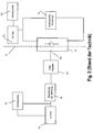
- Fig. 1 represents a schematic diagram of a conventional motor vehicle electrical system with a battery voltage of 12 V (volts).
- the power supply of the electrical system is performed by a voltage source 10, in particular a vehicle battery (accumulator).
- the electrical system also includes a generator (not shown in the picture), which during engine operation serves both to recharge the battery as well as for the direct supply of electrical energy in the motor vehicle electrical system.
- the motor vehicle electrical system includes a number of consumers (vehicle electrical components such as lighting, injection pump, entertainment and information electronics, windscreen wipers, windows and others). This is shown in the schematic diagram of the Fig. 1 summarized in block 12.
- a motor vehicle heating device or air conditioning system is shown in the image separately in the block 16.
- Their control is generally via a control element 14, in particular a power semiconductor.
- a control signal generated by a suitable component of the control electronics 18 (for example a microcontroller .mu.C) is applied to a control terminal St of the switching element (power semiconductor) 14.
- the power can be controlled in the pitch circle with the heater.
- Fig. 1 only schematically a single, the heater symbolizing, consumer 16, combined with a single switching element 14 is shown, the heater usually consists of a plurality of separately controllable components (heating stages) which can then be controlled separately via a plurality of switching elements.
- Points of contact between the two subnetworks result from the fact that the control electronics for the high-current consumers, in particular heating / air conditioning units, continue to be in the area of the sub-network with the lower voltage.
- the control electronics 18 controls the control electronics 18 from the subnet with lower voltage out by applying appropriate voltage signals to the control terminals St of the power semiconductor 14 so that currents are switched in the subnet with higher voltage for the high-current consumers via the power semiconductors.
- galvanic isolation of the subnetworks is used in conventional two-voltage on-board networks with the aid of optocouplers (which react quickly) or alternatively inductive couplers (which react much more slowly).
- Fig. 2 is a schematic diagram of a conventional two-voltage vehicle electrical system with an optocoupler 24 for the galvanic separation of both subnetworks.
- the control electronics 18 preferably comprises a microcontroller ( ⁇ C).
- ⁇ C microcontroller
- the control electronics 18 preferably comprises a microcontroller ( ⁇ C).
- ⁇ C microcontroller
- the control electronics 18 preferably comprises a microcontroller ( ⁇ C).
- ⁇ C microcontroller
- the right side of the subnet is shown with higher battery voltage (for example, 48 volts).
- additional consumers (16 and 22) in addition to the voltage source. These consumers include in particular a heater 16, shown separately in the picture. Other consumers are summarized in block 22.
- a switching element 14 in particular a power semiconductor (control terminal St).
- a plurality of switching elements for switching a plurality of consumers, for example a plurality of heating stages, may be present in an analogous manner.
- the optocoupler 24 is provided as a security element for galvanic isolation between the left and the right subnet. This prevents the voltage from 48 V from reaching the 12 V subnet and thus destroying components of this subnet.
- FIG Fig. 3 A corresponding embodiment of the present invention is shown schematically in FIG Fig. 3 shown.
- the same reference numerals mean corresponding elements, so that a further detailed description is omitted.
- a voltage divider 32 is connected between the control terminal St of the power semiconductor 14 and the 12 V subnet, in particular the control electronics 18.
- This comprises a resistance element 32b, which is connected at one end to the control terminal St of the power semiconductor 14.
- the other terminal of the resistance element (connection point V) is connected on the one hand to the 12 V subnetwork, and on the other hand via another resistor element 32a to ground.
- the value of the resistor 32b is three times as large (3R) as the value of the resistor 32a (R).
- the ratio of the total resistance (sum of the resistance values of 32a and 32b) to the resistance value of 32a must be (at least) the ratio of the rated voltages in the higher and lower voltage subnets (4: 1 in the present case).
- the internal resistance connected in parallel to the resistor 32a must generally be taken into account at the output of the controller 18, in particular at the microcontroller output. However, its value is not always precisely determined and can also change in the event of a fault (if, for example, a transistor is alloyed at the control output). Due to the parallel connection of the resistance of the ⁇ C output and the resistor 32a, however, the additional consideration of the former effectively always results in a reduction in the ground-connected resistance. At a ratio of the total resistance of 32a and 32b to the grounded resistance 32a corresponding to the ratio of the rated voltages (in the example discussed here 1: 4), one is therefore on the safe side.
- the resistors of the voltage divider do not disturb the control behavior of the power semiconductor 14 in normal operation.
- the resistor 32a of the voltage divider can be achieved by an appropriate dimensioning of the resistor 32a of the voltage divider, that even over this from the direction of the 12 V subnetwork in the normal operation direction earth flowing "leakage" remains so low that it does not significantly affect the control or switching behavior caused.
- the resistor 32a (R) and thus indirectly also the resistor 32b (at least 3R) must not become too small in order to ensure proper operation of the switching element 14 in control operation.
- the controlled component in particular the heater, has already failed or has been destroyed.
- the invention makes it possible to spread the damage to other vehicle components in the 12th V subnet to prevent. If 48 V were applied to the 12 V vehicle electrical system, there would be the risk that apart from the heater, which had already failed with the alloying, the components connected to the 12 V vehicle electrical system, such as servomotors and the heating control unit, would also be destroyed.
- Plausibility checks are carried out to check whether an error has occurred (in particular, breakdown of a circuit breaker): Control commands for activating / deactivating a heating stage are output and the corresponding current is checked. If the current flow does not match the control commands, there is an error and the heating will switch off automatically.
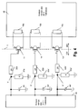
- FIG Fig. 4 A further exemplary representation of the two-voltage on-board electrical system according to the invention is shown in FIG Fig. 4 shown.
- each of the heating stages is associated with its own power semiconductor 14, 14 ', 14 ", whose electrodes S (source) and D (drain) (terminals of the high-current consumers) are connected to the respective load
- a control electrode G gate corresponds to the control connection in FIG Fig. 3
- the voltage divider 32, 32 ', 32 consists of two resistance elements, one of which (32a, 32a', 32a") is connected to the connection point V (V ', V ") connected and connected to ground.
- a cut-off capacitor 44 (44', 44") between the connection point V (V ', V ") and ground, which is used primarily to stabilize the control voltage of the MOSFET 14 (FIG. 14 ', 14 ") in the face of a Leakage current through the resistor 32a (32a ', 32a ") serves as well as in the event of a fault should temporarily suppress higher voltage spikes.
- the circuit according to the invention thus makes it possible, in the event of a fault, during the alloying of only one of the power semiconductors, to protect the 12 V subnetwork from reaching 48 V of voltage.
- the present invention relates to a motor vehicle electrical system according to claim 1 with two different operating voltages, are controlled in the power semiconductor for switching currents in a subnetwork with higher operating voltage from a subnetwork with lower operating voltage out.
- the invention enables a secure protection of components in the subnetwork with lower operating voltage in case of failure, when alloying a power semiconductor, without a costly electrical isolation of both subnets is required by means of expensive components.
- the required protection against reaching the higher voltage on the components with low operating voltage is achieved by the use of a correspondingly dimensioned voltage divider.
Landscapes
- Engineering & Computer Science (AREA)
- Mechanical Engineering (AREA)
- Air-Conditioning For Vehicles (AREA)
- Electric Propulsion And Braking For Vehicles (AREA)
Claims (13)
- Réseau de bord de véhicule automobile, comprenant un premier réseau partiel (40) avec une première source de tension (10) et des premiers récepteurs-consommateurs (12), ainsi qu'un deuxième réseau partiel (48) avec une deuxième source de tension (20) et des deuxièmes récepteurs-consommateurs (16, 22), réseau
dans lequel la deuxième source de tension (20) fournit une tension plus élevée que la première source de tension (10), et
dans lequel il existe une liaison entre le premier (40) et le deuxième réseau partiel (48) par l'intermédiaire d'au moins un élément de commutation (14, 14', 14''), qui comprend une borne de commande (St, G) et est commandé à partir du premier réseau partiel (40), en vue de commuter des courants dans le deuxième réseau partiel (48),
caractérisé en ce que
la borne de commande (St, G) dudit au moins un élément de commutation (14, 14', 14'') est reliée au premier réseau partiel (40) par l'intermédiaire d'un diviseur de tension (32, 32', 32''), qui, en cas de disfonctionnements, empêche que la tension plus élevée du deuxième réseau partiel (48) passe dans le premier réseau partiel (40). - Réseau de bord de véhicule automobile selon la revendication 1, dans lequel l'élément de commutation (14, 14', 14'') comprend un semi-conducteur de puissance.
- Réseau de bord de véhicule automobile selon la revendication 2, dans lequel l'élément de commutation (14, 14', 14'') est un MOSFET (transistor à effet de champ).
- Réseau de bord de véhicule automobile selon l'une des revendications 1 à 3, dans lequel les deuxièmes récepteurs-consommateurs (16, 22) englobent un dispositif de chauffage (16), et l'élément de commutation (14, 14', 14'') sert à la commutation du courant de chauffage du dispositif de chauffage (16).
- Réseau de bord de véhicule automobile selon l'une des revendications 1 à 4, dans lequel la liaison entre le premier (40) et le deuxième réseau partiel (48) se fait par l'intermédiaire de plusieurs éléments de commutation (14, 14', 14''), qui sont commandés à partir du premier réseau partiel (40) en vue de commuter des courants dans le deuxième réseau partiel (48).
- Réseau de bord de véhicule automobile selon la revendication 5, dans lequel respectivement un des éléments de commutation (14, 14', 14'') sert à commuter un étage de chauffe respectif d'un dispositif de chauffage (16).
- Réseau de bord de véhicule automobile selon la revendication 6, dans lequel respectivement un étage de chauffe (16a, 16b, 16c) comprend un ou plusieurs éléments à coefficient de température positif dits éléments PTC.
- Réseau de bord de véhicule automobile selon l'une des revendications 1 à 7, dans lequel la tension fournie par la deuxième source de tension (20) est plus grande que la tension fournie par la première source de tension (10), d'un facteur supérieur à deux.
- Réseau de bord de véhicule automobile selon la revendication 8, dans lequel la tension fournie par la deuxième source de tension (20) est égale à quatre fois la tension fournie par la première source de tension (10).
- Réseau de bord de véhicule automobile selon l'une des revendications 1 à 9, dans lequel la tension fournie par la première source de tension (10) vaut 12 Volt.
- Réseau de bord de véhicule automobile selon l'une des revendications 1 à 10, dans lequel le diviseur de tension (32, 32', 32'') comprend deux éléments de résistance (32a, 32b, 32a', 32b', 32a'', 32b''),
et dans lequel le rapport de la valeur de la résistance totale, constituée de la somme des valeurs de résistance d'un premier élément de résistance (32a, 32a', 32a'') relié directement à la terre et d'un deuxième élément de résistance (32b, 32b', 32b'') relié directement à l'élément de commutation (14, 14', 14''), à la valeur de résistance du premier élément de résistance (32b, 32b', 32b''), est égal au rapport d'une tension dans le deuxième réseau partiel (48) à une tension dans le premier réseau partiel (40). - Réseau de bord de véhicule automobile selon la revendication 11, dans lequel la connexion de branchement du premier réseau partiel (40) est effectuée au point de jonction (V, V, V'') des deux éléments de résistance du diviseur de tension (32, 32', 32'').
- Réseau de bord de véhicule automobile selon la revendication 12, dans lequel un condensateur d'isolement (44, 44', 44'') est monté en parallèle au premier élément de résistance (32b, 32b', 32b''), entre le point de jonction (V, V', V'') des éléments de résistance et la terre.
Priority Applications (1)
| Application Number | Priority Date | Filing Date | Title |
|---|---|---|---|
| EP12185194.3A EP2711248B1 (fr) | 2012-09-20 | 2012-09-20 | Réseau de bord bitension avec protection contre les surtensions |
Applications Claiming Priority (1)
| Application Number | Priority Date | Filing Date | Title |
|---|---|---|---|
| EP12185194.3A EP2711248B1 (fr) | 2012-09-20 | 2012-09-20 | Réseau de bord bitension avec protection contre les surtensions |
Publications (2)
| Publication Number | Publication Date |
|---|---|
| EP2711248A1 EP2711248A1 (fr) | 2014-03-26 |
| EP2711248B1 true EP2711248B1 (fr) | 2014-11-05 |
Family
ID=47022483
Family Applications (1)
| Application Number | Title | Priority Date | Filing Date |
|---|---|---|---|
| EP12185194.3A Not-in-force EP2711248B1 (fr) | 2012-09-20 | 2012-09-20 | Réseau de bord bitension avec protection contre les surtensions |
Country Status (1)
| Country | Link |
|---|---|
| EP (1) | EP2711248B1 (fr) |
Cited By (2)
| Publication number | Priority date | Publication date | Assignee | Title |
|---|---|---|---|---|
| CN106564406A (zh) * | 2016-11-02 | 2017-04-19 | 孙立 | 用于电动交通工具的双能源动力总成系统及其控制方法 |
| CN108966385A (zh) * | 2017-05-17 | 2018-12-07 | 马勒国际有限公司 | 用于机动车的加热器 |
Families Citing this family (8)
| Publication number | Priority date | Publication date | Assignee | Title |
|---|---|---|---|---|
| FR3021764B1 (fr) * | 2014-05-27 | 2016-05-27 | Valeo Systemes Thermiques | Dispositif electrique ou electronique a deux tensions d'alimentation |
| DE102016213845A1 (de) | 2016-07-28 | 2018-02-01 | Robert Bosch Gmbh | Diagnoseverfahren zum Ermitteln eines Betriebszustandes eines Batteriesystems, Controller und Batteriesystem |
| FR3056876B1 (fr) * | 2016-09-23 | 2020-10-23 | Valeo Systemes Thermiques | Dispositif de chauffage electrique pour vehicule automobile alimente par deux reseaux d'alimentation electiques |
| FR3056709B1 (fr) * | 2016-09-23 | 2020-01-17 | Valeo Systemes Thermiques | Pulseur d'air pour vehicule automobile alimente par deux reseaux d'alimentation electriques |
| FR3056875A1 (fr) * | 2016-09-23 | 2018-03-30 | Valeo Systemes Thermiques | Dispositif de chauffage electrique pour vehicule automobile alimente par deux reseaux d'alimentation electriques |
| EP3403885B1 (fr) * | 2017-05-17 | 2019-11-20 | Mahle International GmbH | Système électrique de véhicule automobile embarqué |
| EP3403886B1 (fr) | 2017-05-17 | 2019-12-18 | Mahle International GmbH | Système électrique de véhicule automobile embarqué |
| DE102019218348A1 (de) | 2019-11-27 | 2021-05-27 | Eberspächer Catem Gmbh & Co. Kg | Elektrische heizvorrichtung für ein kraftfahrzeug |
Family Cites Families (2)
| Publication number | Priority date | Publication date | Assignee | Title |
|---|---|---|---|---|
| JPS58206444A (ja) * | 1982-05-27 | 1983-12-01 | Nissan Motor Co Ltd | 車両用電源回路 |
| DE10248415B4 (de) * | 2002-10-17 | 2006-03-09 | Audi Ag | Stromversorgungsschaltung für ein Kraftfahrzeug mit zwei unterschiedlichen Verbraucherspannungen |
-
2012
- 2012-09-20 EP EP12185194.3A patent/EP2711248B1/fr not_active Not-in-force
Cited By (3)
| Publication number | Priority date | Publication date | Assignee | Title |
|---|---|---|---|---|
| CN106564406A (zh) * | 2016-11-02 | 2017-04-19 | 孙立 | 用于电动交通工具的双能源动力总成系统及其控制方法 |
| CN106564406B (zh) * | 2016-11-02 | 2019-07-23 | 孙立 | 用于电动交通工具的双能源动力总成系统及其控制方法 |
| CN108966385A (zh) * | 2017-05-17 | 2018-12-07 | 马勒国际有限公司 | 用于机动车的加热器 |
Also Published As
| Publication number | Publication date |
|---|---|
| EP2711248A1 (fr) | 2014-03-26 |
Similar Documents
| Publication | Publication Date | Title |
|---|---|---|
| EP2711248B1 (fr) | Réseau de bord bitension avec protection contre les surtensions | |
| DE102014105106B4 (de) | Intelligente Leistungsverteilungseinheit | |
| WO2015014551A1 (fr) | Protection contre les surtensions pour un réseau de bord à multiples tensions | |
| DE112018001229T5 (de) | Steuervorrichtung für eine Bord-Stromversorgungseinheit und Bord-Stromversorgungsvorrichtung | |
| DE10113081C1 (de) | Anordnung und Verfahren zum Schutz eines Mehrspannungsbordnetzes gegen Spannungsüberschläge zwischen verschiedenen Spannungsebenen sowie gegen Verpolung von außen | |
| DE102013208968B4 (de) | Kraftfahrzeugbordnetz mit aktivem Brückengleichrichter und Überspannungsschutz bei Lastabwurf, Gleichrichteranordnung, zugehöriges Betriebsverfahren und Mittel zu dessen Implementierung | |
| DE102012222208A1 (de) | Verfahren zum gesteuerten Verbinden mehrerer Bordnetzzweige eines Fahrzeugs, Steuereinheit zur Ausführung des Verfahrens sowie Bordnetz | |
| EP2953227A1 (fr) | Réseau de bord pour un véhicule automobile | |
| DE102006047243A1 (de) | Bordnetz mit mindestens einem Leistungstransistor und Verfahren zum Schutz eines Bordnetzes | |
| DE102012218914A1 (de) | Schutzschaltungsanordnung für ein Mehrspannungsnetz | |
| DE102013213802A1 (de) | Überspannungsschutz für aktive Gleichrichter bei Lastabwurf | |
| WO2022219023A1 (fr) | Réseau de bord électrique pour un véhicule, véhicule équipé d'un réseau de bord électrique, et procédé permettant de faire fonctionner un réseau de bord électrique pour un véhicule | |
| WO2021078441A1 (fr) | Système électronique d'alimentation en tension | |
| WO2019149416A1 (fr) | Dispositif de protection d'au moins un consommateur | |
| WO2006099984A1 (fr) | Circuit d'alimentation en courant pour automobile a consommateurs electriques appropries en termes de haute securite | |
| DE102012216806A1 (de) | Pulsweitenmodulations-Steuerung | |
| DE102011105971A1 (de) | Bordnetzanordnung für ein Kraftfahrzeug | |
| DE102016121447A1 (de) | Vorrichtung und Verfahren zum Absichern einer Bordnetzkomponente eines Fahrzeug-Bordnetzes | |
| EP2469070B1 (fr) | Limitation de l'introduction de la tension de démarrage dans un réseau de bord de véhicule automobile | |
| EP1782527B1 (fr) | Dispositif d'alimentation de groupes auxiliaires destines a un vehicule propulsé par combustible ou électricité | |
| DE102019202345B4 (de) | Fahrzeugbordnetz mit einem Akkumulator, einem Wechselspannungsanschluss und einem Gleichspannungsanschluss | |
| DE102011122342A1 (de) | Anordnung mit zwei Fahrzeugbauteilen, insbesondere einer Lenksäule und einem Lenkrad, und Kraftfahrzeug mit einer Anordnung | |
| DE102017204091A1 (de) | Schaltvorrichtung zum Schalten eines elektrischen Erregerstroms für eine elektrische Maschine mit einem Läufer | |
| DE102022131938B3 (de) | Vorrichtung zum bereitstellen einer oder mehrerer funktionsspannungen in einem fahrzeugbordnetz | |
| DE102022133875B4 (de) | Begrenzung der Spannung im Rekuperationsbetrieb |
Legal Events
| Date | Code | Title | Description |
|---|---|---|---|
| PUAI | Public reference made under article 153(3) epc to a published international application that has entered the european phase |
Free format text: ORIGINAL CODE: 0009012 |
|
| 17P | Request for examination filed |
Effective date: 20130424 |
|
| AK | Designated contracting states |
Kind code of ref document: A1 Designated state(s): AL AT BE BG CH CY CZ DE DK EE ES FI FR GB GR HR HU IE IS IT LI LT LU LV MC MK MT NL NO PL PT RO RS SE SI SK SM TR |
|
| AX | Request for extension of the european patent |
Extension state: BA ME |
|
| REG | Reference to a national code |
Ref country code: DE Ref legal event code: R079 Ref document number: 502012001531 Country of ref document: DE Free format text: PREVIOUS MAIN CLASS: B60R0016030000 Ipc: H02H0003000000 |
|
| GRAP | Despatch of communication of intention to grant a patent |
Free format text: ORIGINAL CODE: EPIDOSNIGR1 |
|
| RIC1 | Information provided on ipc code assigned before grant |
Ipc: H02H 3/00 20060101AFI20140527BHEP Ipc: B60R 16/03 20060101ALI20140527BHEP |
|
| INTG | Intention to grant announced |
Effective date: 20140613 |
|
| GRAS | Grant fee paid |
Free format text: ORIGINAL CODE: EPIDOSNIGR3 |
|
| GRAA | (expected) grant |
Free format text: ORIGINAL CODE: 0009210 |
|
| AK | Designated contracting states |
Kind code of ref document: B1 Designated state(s): AL AT BE BG CH CY CZ DE DK EE ES FI FR GB GR HR HU IE IS IT LI LT LU LV MC MK MT NL NO PL PT RO RS SE SI SK SM TR |
|
| REG | Reference to a national code |
Ref country code: GB Ref legal event code: FG4D Free format text: NOT ENGLISH |
|
| REG | Reference to a national code |
Ref country code: CH Ref legal event code: EP |
|
| REG | Reference to a national code |
Ref country code: AT Ref legal event code: REF Ref document number: 695038 Country of ref document: AT Kind code of ref document: T Effective date: 20141115 |
|
| REG | Reference to a national code |
Ref country code: IE Ref legal event code: FG4D Free format text: LANGUAGE OF EP DOCUMENT: GERMAN |
|
| REG | Reference to a national code |
Ref country code: DE Ref legal event code: R096 Ref document number: 502012001531 Country of ref document: DE Effective date: 20141224 |
|
| REG | Reference to a national code |
Ref country code: NL Ref legal event code: VDEP Effective date: 20141105 |
|
| REG | Reference to a national code |
Ref country code: LT Ref legal event code: MG4D |
|
| PG25 | Lapsed in a contracting state [announced via postgrant information from national office to epo] |
Ref country code: LT Free format text: LAPSE BECAUSE OF FAILURE TO SUBMIT A TRANSLATION OF THE DESCRIPTION OR TO PAY THE FEE WITHIN THE PRESCRIBED TIME-LIMIT Effective date: 20141105 Ref country code: IS Free format text: LAPSE BECAUSE OF FAILURE TO SUBMIT A TRANSLATION OF THE DESCRIPTION OR TO PAY THE FEE WITHIN THE PRESCRIBED TIME-LIMIT Effective date: 20150305 Ref country code: ES Free format text: LAPSE BECAUSE OF FAILURE TO SUBMIT A TRANSLATION OF THE DESCRIPTION OR TO PAY THE FEE WITHIN THE PRESCRIBED TIME-LIMIT Effective date: 20141105 Ref country code: FI Free format text: LAPSE BECAUSE OF FAILURE TO SUBMIT A TRANSLATION OF THE DESCRIPTION OR TO PAY THE FEE WITHIN THE PRESCRIBED TIME-LIMIT Effective date: 20141105 Ref country code: NL Free format text: LAPSE BECAUSE OF FAILURE TO SUBMIT A TRANSLATION OF THE DESCRIPTION OR TO PAY THE FEE WITHIN THE PRESCRIBED TIME-LIMIT Effective date: 20141105 Ref country code: PT Free format text: LAPSE BECAUSE OF FAILURE TO SUBMIT A TRANSLATION OF THE DESCRIPTION OR TO PAY THE FEE WITHIN THE PRESCRIBED TIME-LIMIT Effective date: 20150305 Ref country code: NO Free format text: LAPSE BECAUSE OF FAILURE TO SUBMIT A TRANSLATION OF THE DESCRIPTION OR TO PAY THE FEE WITHIN THE PRESCRIBED TIME-LIMIT Effective date: 20150205 |
|
| PG25 | Lapsed in a contracting state [announced via postgrant information from national office to epo] |
Ref country code: PL Free format text: LAPSE BECAUSE OF FAILURE TO SUBMIT A TRANSLATION OF THE DESCRIPTION OR TO PAY THE FEE WITHIN THE PRESCRIBED TIME-LIMIT Effective date: 20141105 Ref country code: CY Free format text: LAPSE BECAUSE OF FAILURE TO SUBMIT A TRANSLATION OF THE DESCRIPTION OR TO PAY THE FEE WITHIN THE PRESCRIBED TIME-LIMIT Effective date: 20141105 Ref country code: SE Free format text: LAPSE BECAUSE OF FAILURE TO SUBMIT A TRANSLATION OF THE DESCRIPTION OR TO PAY THE FEE WITHIN THE PRESCRIBED TIME-LIMIT Effective date: 20141105 Ref country code: RS Free format text: LAPSE BECAUSE OF FAILURE TO SUBMIT A TRANSLATION OF THE DESCRIPTION OR TO PAY THE FEE WITHIN THE PRESCRIBED TIME-LIMIT Effective date: 20141105 Ref country code: LV Free format text: LAPSE BECAUSE OF FAILURE TO SUBMIT A TRANSLATION OF THE DESCRIPTION OR TO PAY THE FEE WITHIN THE PRESCRIBED TIME-LIMIT Effective date: 20141105 Ref country code: GR Free format text: LAPSE BECAUSE OF FAILURE TO SUBMIT A TRANSLATION OF THE DESCRIPTION OR TO PAY THE FEE WITHIN THE PRESCRIBED TIME-LIMIT Effective date: 20150206 Ref country code: HR Free format text: LAPSE BECAUSE OF FAILURE TO SUBMIT A TRANSLATION OF THE DESCRIPTION OR TO PAY THE FEE WITHIN THE PRESCRIBED TIME-LIMIT Effective date: 20141105 |
|
| PG25 | Lapsed in a contracting state [announced via postgrant information from national office to epo] |
Ref country code: CZ Free format text: LAPSE BECAUSE OF FAILURE TO SUBMIT A TRANSLATION OF THE DESCRIPTION OR TO PAY THE FEE WITHIN THE PRESCRIBED TIME-LIMIT Effective date: 20141105 Ref country code: EE Free format text: LAPSE BECAUSE OF FAILURE TO SUBMIT A TRANSLATION OF THE DESCRIPTION OR TO PAY THE FEE WITHIN THE PRESCRIBED TIME-LIMIT Effective date: 20141105 Ref country code: SK Free format text: LAPSE BECAUSE OF FAILURE TO SUBMIT A TRANSLATION OF THE DESCRIPTION OR TO PAY THE FEE WITHIN THE PRESCRIBED TIME-LIMIT Effective date: 20141105 Ref country code: DK Free format text: LAPSE BECAUSE OF FAILURE TO SUBMIT A TRANSLATION OF THE DESCRIPTION OR TO PAY THE FEE WITHIN THE PRESCRIBED TIME-LIMIT Effective date: 20141105 |
|
| REG | Reference to a national code |
Ref country code: DE Ref legal event code: R097 Ref document number: 502012001531 Country of ref document: DE |
|
| PLBE | No opposition filed within time limit |
Free format text: ORIGINAL CODE: 0009261 |
|
| STAA | Information on the status of an ep patent application or granted ep patent |
Free format text: STATUS: NO OPPOSITION FILED WITHIN TIME LIMIT |
|
| 26N | No opposition filed |
Effective date: 20150806 |
|
| PG25 | Lapsed in a contracting state [announced via postgrant information from national office to epo] |
Ref country code: SI Free format text: LAPSE BECAUSE OF FAILURE TO SUBMIT A TRANSLATION OF THE DESCRIPTION OR TO PAY THE FEE WITHIN THE PRESCRIBED TIME-LIMIT Effective date: 20141105 |
|
| PG25 | Lapsed in a contracting state [announced via postgrant information from national office to epo] |
Ref country code: LU Free format text: LAPSE BECAUSE OF FAILURE TO SUBMIT A TRANSLATION OF THE DESCRIPTION OR TO PAY THE FEE WITHIN THE PRESCRIBED TIME-LIMIT Effective date: 20150920 Ref country code: MC Free format text: LAPSE BECAUSE OF FAILURE TO SUBMIT A TRANSLATION OF THE DESCRIPTION OR TO PAY THE FEE WITHIN THE PRESCRIBED TIME-LIMIT Effective date: 20141105 |
|
| REG | Reference to a national code |
Ref country code: CH Ref legal event code: PL |
|
| PG25 | Lapsed in a contracting state [announced via postgrant information from national office to epo] |
Ref country code: RO Free format text: LAPSE BECAUSE OF FAILURE TO SUBMIT A TRANSLATION OF THE DESCRIPTION OR TO PAY THE FEE WITHIN THE PRESCRIBED TIME-LIMIT Effective date: 20141105 |
|
| REG | Reference to a national code |
Ref country code: IE Ref legal event code: MM4A |
|
| PG25 | Lapsed in a contracting state [announced via postgrant information from national office to epo] |
Ref country code: CH Free format text: LAPSE BECAUSE OF NON-PAYMENT OF DUE FEES Effective date: 20150930 Ref country code: LI Free format text: LAPSE BECAUSE OF NON-PAYMENT OF DUE FEES Effective date: 20150930 Ref country code: IE Free format text: LAPSE BECAUSE OF NON-PAYMENT OF DUE FEES Effective date: 20150920 |
|
| REG | Reference to a national code |
Ref country code: FR Ref legal event code: PLFP Year of fee payment: 5 |
|
| PG25 | Lapsed in a contracting state [announced via postgrant information from national office to epo] |
Ref country code: MT Free format text: LAPSE BECAUSE OF FAILURE TO SUBMIT A TRANSLATION OF THE DESCRIPTION OR TO PAY THE FEE WITHIN THE PRESCRIBED TIME-LIMIT Effective date: 20141105 |
|
| GBPC | Gb: european patent ceased through non-payment of renewal fee |
Effective date: 20160920 |
|
| PG25 | Lapsed in a contracting state [announced via postgrant information from national office to epo] |
Ref country code: HU Free format text: LAPSE BECAUSE OF FAILURE TO SUBMIT A TRANSLATION OF THE DESCRIPTION OR TO PAY THE FEE WITHIN THE PRESCRIBED TIME-LIMIT; INVALID AB INITIO Effective date: 20120920 Ref country code: BG Free format text: LAPSE BECAUSE OF FAILURE TO SUBMIT A TRANSLATION OF THE DESCRIPTION OR TO PAY THE FEE WITHIN THE PRESCRIBED TIME-LIMIT Effective date: 20141105 Ref country code: SM Free format text: LAPSE BECAUSE OF FAILURE TO SUBMIT A TRANSLATION OF THE DESCRIPTION OR TO PAY THE FEE WITHIN THE PRESCRIBED TIME-LIMIT Effective date: 20141105 |
|
| PG25 | Lapsed in a contracting state [announced via postgrant information from national office to epo] |
Ref country code: BE Free format text: LAPSE BECAUSE OF NON-PAYMENT OF DUE FEES Effective date: 20150930 Ref country code: GB Free format text: LAPSE BECAUSE OF NON-PAYMENT OF DUE FEES Effective date: 20160920 |
|
| REG | Reference to a national code |
Ref country code: FR Ref legal event code: PLFP Year of fee payment: 6 |
|
| PG25 | Lapsed in a contracting state [announced via postgrant information from national office to epo] |
Ref country code: MK Free format text: LAPSE BECAUSE OF FAILURE TO SUBMIT A TRANSLATION OF THE DESCRIPTION OR TO PAY THE FEE WITHIN THE PRESCRIBED TIME-LIMIT Effective date: 20141105 Ref country code: TR Free format text: LAPSE BECAUSE OF FAILURE TO SUBMIT A TRANSLATION OF THE DESCRIPTION OR TO PAY THE FEE WITHIN THE PRESCRIBED TIME-LIMIT Effective date: 20141105 |
|
| REG | Reference to a national code |
Ref country code: FR Ref legal event code: PLFP Year of fee payment: 7 |
|
| PG25 | Lapsed in a contracting state [announced via postgrant information from national office to epo] |
Ref country code: AL Free format text: LAPSE BECAUSE OF FAILURE TO SUBMIT A TRANSLATION OF THE DESCRIPTION OR TO PAY THE FEE WITHIN THE PRESCRIBED TIME-LIMIT Effective date: 20141105 |
|
| REG | Reference to a national code |
Ref country code: AT Ref legal event code: MM01 Ref document number: 695038 Country of ref document: AT Kind code of ref document: T Effective date: 20170920 |
|
| PG25 | Lapsed in a contracting state [announced via postgrant information from national office to epo] |
Ref country code: AT Free format text: LAPSE BECAUSE OF NON-PAYMENT OF DUE FEES Effective date: 20170920 |
|
| REG | Reference to a national code |
Ref country code: FR Ref legal event code: PLFP Year of fee payment: 11 |
|
| PGFP | Annual fee paid to national office [announced via postgrant information from national office to epo] |
Ref country code: FR Payment date: 20230918 Year of fee payment: 12 Ref country code: DE Payment date: 20230919 Year of fee payment: 12 |
|
| PGFP | Annual fee paid to national office [announced via postgrant information from national office to epo] |
Ref country code: IT Payment date: 20230929 Year of fee payment: 12 |
|
| REG | Reference to a national code |
Ref country code: DE Ref legal event code: R119 Ref document number: 502012001531 Country of ref document: DE |
|
| PG25 | Lapsed in a contracting state [announced via postgrant information from national office to epo] |
Ref country code: DE Free format text: LAPSE BECAUSE OF NON-PAYMENT OF DUE FEES Effective date: 20250401 |
|
| PG25 | Lapsed in a contracting state [announced via postgrant information from national office to epo] |
Ref country code: IT Free format text: LAPSE BECAUSE OF NON-PAYMENT OF DUE FEES Effective date: 20240920 |
|
| PG25 | Lapsed in a contracting state [announced via postgrant information from national office to epo] |
Ref country code: FR Free format text: LAPSE BECAUSE OF NON-PAYMENT OF DUE FEES Effective date: 20240930 |