EP2711254A2 - Deflektorvorrichtung - Google Patents
Deflektorvorrichtung Download PDFInfo
- Publication number
- EP2711254A2 EP2711254A2 EP13185745.0A EP13185745A EP2711254A2 EP 2711254 A2 EP2711254 A2 EP 2711254A2 EP 13185745 A EP13185745 A EP 13185745A EP 2711254 A2 EP2711254 A2 EP 2711254A2
- Authority
- EP
- European Patent Office
- Prior art keywords
- movable portion
- vehicle
- protrusion amount
- roof panel
- vehicle speed
- Prior art date
- Legal status (The legal status is an assumption and is not a legal conclusion. Google has not performed a legal analysis and makes no representation as to the accuracy of the status listed.)
- Granted
Links
- 230000007423 decrease Effects 0.000 claims abstract description 30
- 230000001105 regulatory effect Effects 0.000 claims abstract description 4
- 239000000446 fuel Substances 0.000 description 9
- 230000001133 acceleration Effects 0.000 description 5
- 238000010276 construction Methods 0.000 description 4
- 230000006866 deterioration Effects 0.000 description 4
- 238000010586 diagram Methods 0.000 description 3
- 238000000034 method Methods 0.000 description 3
- 238000001514 detection method Methods 0.000 description 2
- 238000012986 modification Methods 0.000 description 2
- 230000004048 modification Effects 0.000 description 2
- 230000001276 controlling effect Effects 0.000 description 1
- 230000002542 deteriorative effect Effects 0.000 description 1
- 239000000428 dust Substances 0.000 description 1
- 238000005265 energy consumption Methods 0.000 description 1
Images



Classifications
-
- B—PERFORMING OPERATIONS; TRANSPORTING
- B62—LAND VEHICLES FOR TRAVELLING OTHERWISE THAN ON RAILS
- B62D—MOTOR VEHICLES; TRAILERS
- B62D35/00—Vehicle bodies characterised by streamlining
- B62D35/007—Rear spoilers
-
- B—PERFORMING OPERATIONS; TRANSPORTING
- B60—VEHICLES IN GENERAL
- B60S—SERVICING, CLEANING, REPAIRING, SUPPORTING, LIFTING, OR MANOEUVRING OF VEHICLES, NOT OTHERWISE PROVIDED FOR
- B60S1/00—Cleaning of vehicles
- B60S1/02—Cleaning windscreens, windows or optical devices
- B60S1/56—Cleaning windscreens, windows or optical devices specially adapted for cleaning other parts or devices than front windows or windscreens
- B60S1/58—Cleaning windscreens, windows or optical devices specially adapted for cleaning other parts or devices than front windows or windscreens for rear windows
-
- Y—GENERAL TAGGING OF NEW TECHNOLOGICAL DEVELOPMENTS; GENERAL TAGGING OF CROSS-SECTIONAL TECHNOLOGIES SPANNING OVER SEVERAL SECTIONS OF THE IPC; TECHNICAL SUBJECTS COVERED BY FORMER USPC CROSS-REFERENCE ART COLLECTIONS [XRACs] AND DIGESTS
- Y02—TECHNOLOGIES OR APPLICATIONS FOR MITIGATION OR ADAPTATION AGAINST CLIMATE CHANGE
- Y02T—CLIMATE CHANGE MITIGATION TECHNOLOGIES RELATED TO TRANSPORTATION
- Y02T10/00—Road transport of goods or passengers
- Y02T10/80—Technologies aiming to reduce greenhouse gasses emissions common to all road transportation technologies
- Y02T10/82—Elements for improving aerodynamics
Definitions
- This disclosure generally relates to a deflector apparatus.
- Patent reference 1 A known deflector (roof spoiler) arranged at a rear of a roof panel and an upper of a rear window of a vehicle and extended in a vehicle width direction is disclosed in JPH10-24869A (hereinafter referred to as Patent reference 1).
- a position, or attitude (an angle) of the deflector is changed in accordance with weather.
- the position, or attitude of the deflector is controlled so that an upper surface of the deflector is positioned horizontally, and substantially planar with an upper surface of the roof panel.
- a clearance is formed between the deflector and the upper of the rear window and a part of air flowing from front to rear of the vehicle along the upper surface of the roof panel flows along the rear window via the clearance. Accordingly, the adhesion of the dirt, for example, rain, mud and dust to the rear window may be reduced.
- a front end portion of the deflector is substantially planar with the upper surface of the roof panel and the position, or attitude of the deflector is controlled so that a rear end portion of the upper surface of the deflector is positioned lower than the front end portion of the upper surface of the deflector.
- the clearance is closed and air flowing from the front to the rear of the vehicle along the upper surface of the roof panel is introduced to the rear of the vehicle without flowing toward the rear window.
- the deflector is configured not to be protruded higher than the upper surface of the roof panel in order to reduce air resistance in rainy weather and fine weather as much as possible.
- an amount of air flowing along the rear window via the clearance is small.
- the amount of air flowing along the rear window is very small. Accordingly, the adhesion of the dirt to the rear window may be reduced sufficiently.
- a deflector apparatus for regulating air flows at a rear of a vehicle includes a movable portion arranged at a rear of a roof panel and an upper of a rear window of a vehicle and extended in a vehicle width direction.
- the movable portion is movable to increase and decrease a protrusion amount of a front end portion of the movable portion in a vehicle front-rear direction from an upper surface of the roof panel to upward.
- the deflector apparatus further includes a driving system for driving the movable portion to decrease the protrusion amount as a vehicle speed increases to decrease an amount of air introduced by the movable portion and flowing along the rear window.
- the driving system drives the movable portion to increase the protrusion amount as the vehicle speed decreases to increase the amount of air introduced by the movable portion and flowing along the rear window.
- the deflector apparatus sufficiently prevents the dirt from adhering to the rear window while suppressing the deterioration of fuel efficiency due to the increase of air resistance regardless of a magnitude of the vehicle speed.
- a rear end portion of the movable portion in the vehicle front-rear direction is positioned lower than the front end portion of the movable portion in the vehicle front-rear direction while the front end portion of the movable portion in the vehicle front-rear direction protrudes higher than the upper surface of the roof panel.
- a part of air flowing from the front to the rear of the vehicle along the upper surface of the roof panel is introduced obliquely downward along a lower surface of the movable portion. Accordingly, air introduced by the movable portion 11 may easily flow along the rear window. Thus, the adhesion of the dirt to the rear window may be reduced further reliably.
- the deflector apparatus further includes a fixed portion arranged at opposing ends of the movable portion in the vehicle width direction and extended in the vehicle width direction.
- the fixed portion is fixed at a rear end portion of the roof panel in the vehicle front-rear direction.
- the movable portion is arranged at a center in the vehicle width direction.
- the adhesion of the dirt to the rear window in the vehicle width direction may be reduced, particularly at the center portion of the rear window in the vehicle width direction.
- a rear view of the vehicle in bad weather may be sufficiently maintained.
- a length of the movable portion in the vehicle width direction is short (for example, approximately a half of the vehicle width)
- air resistance due to the protrusion of the movable portion higher than the upper surface of the roof panel is increased only by a small amount. Accordingly, the deterioration of fuel efficiency may be minimized.
- a space below the fixed portion may be maintained for arranging the driving system which drives the movable portion.
- the driving system decreases the protrusion amount of the movable portion in a stepwise manner as the vehicle speed increases and increases the protrusion amount of the movable portion in a stepwise manner as the vehicle speed decreases.
- the movable portion is configured to change the protrusion amount continuously in accordance with the increase (decrease) of the vehicle speed
- structures of, for example, an actuator and a link mechanism need to be complex in order to control the protrusion amount of the movable portion precisely.
- the actuator and the link mechanism may have comparatively simple configurations and may achieve a precise control of the protrusion amount of the movable portion at a sufficient level.
- the movable portion In a case where the movable portion is configured to change the protrusion amount continuously in accordance with the increase (decrease) of the vehicle speed, the movable portion is driven due to even a slight change of the vehicle speed. In a case where the movable portion is driven due to a slight change of the vehicle speed, energy (for example, power) consumption for driving the movable portion is increased. In contrast, according to the embodiment, the protrusion amount of the movable portion is changed in a stepwise manner. That is, the movable portion is driven only when the vehicle speed exceeds a predetermined threshold value. Thus, energy consumption may be reduced.
- the driving system includes a weather determination device determining a weather condition and drives the movable portion to position an upper surface of the movable portion and the upper surface of the roof panel RP in a planar manner regardless of the magnitude of the vehicle speed when the weather determination device determines that the weather is fine.
- the movable portion does not need to protrude higher than the upper surface of the roof panel to flow air toward the rear window.
- the upper surface of the movable portion and the upper surface of the roof panel are positioned in a planar manner regardless of vehicle speed. That is, the movable portion is flushed with the roof panel. Thus, air resistance may be prevented from being unnecessarily increased in fine weather.
- the front end portion of the movable portion in the vehicle front-rear direction is in contact with the rear end portion of the roof panel in the vehicle front-rear direction while an upper surface of the movable portion and the upper surface of the roof panel are positioned in a planar manner.
- the front end portion of the movable portion in the vehicle front-rear direction and the rear end portion of the roof panel in the vehicle front-rear direction are in contact with one another and no clearance is formed between the movable portion and the roof panel. Accordingly, air flowing from the front to the rear of the vehicle along the upper surface of the roof panel flows smoothly toward the rear of the vehicle. Thus, air resistance may be prevented from being increased.
- the deflector apparatus further includes a shaft mounted to the rear end portion of the movable portion at the rear of the vehicle.
- the movable portion is configured to pivot about the shaft.
- the driving system controls a pivot angle of the movable portion.
- the deflector apparatus further includes a slide rail mounted to the movable portion at the rear of the vehicle.
- the movable portion is configured to be slidable either obliquely forward and upward or obliquely backward and downward.
- the driving system controls a sliding amount of the movable portion.
- the front end portion and the rear end portion of the movable portion are positioned at a same height.
- the driving system controls the protrusion amount to decrease in a stepwise manner in a case where the vehicle speed increases and the protrusion amount to increase in a stepwise manner in a case where the vehicle speed decreases using separate tables.
- the weather determination device determines the weather condition by detecting an on/off state of the switch of the wiper.
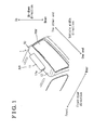
- Fig. 1 is a perspective view, seeing from an obliquely upward, of a rear portion of a vehicle including a deflector apparatus according to an embodiment disclosed here;
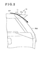
- Fig. 2 is a side view of the rear portion of the vehicle in Fig. 1 according to the embodiment;
- Fig. 3 is a block diagram of the deflector apparatus in Fig. 1 according to the embodiment
- Fig. 4 is a flowchart illustrating a movable portion control program according to the embodiment
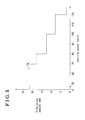
- Fig. 5 is a conceptual diagram of a table illustrating a relation of a vehicle speed and a protrusion amount of a movable portion according to the embodiment
- Fig. 6 is a side view of the rear portion of the vehicle including the deflector apparatus of a modified example of the embodiment
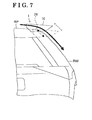
- Fig. 7 is a side view of the rear portion of the vehicle including the deflector apparatus of another modified example of the embodiment.
- Fig. 8 is a conceptual diagram of another table illustrating the relation of the vehicle speed and the protrusion amount of the movable portion according to the embodiment.
- a deflector apparatus 1 of the embodiment includes a deflector body portion 10 regulating air flows at a rear of a vehicle.
- the deflector body portion 10 is arranged at a rear of a roof panel RP and an upper of a rear window RW of the vehicle and extends in a vehicle width direction.
- the deflector body portion 10 includes a movable portion 11 and a fixed portion 12 both formed in a board shape and extending in the vehicle width direction.
- the movable portion 11 is arranged at a center in the vehicle width direction while the fixed portion 12 is formed to surround opposing ends of the movable portion 11 in the vehicle width direction and a rear portion of the movable portion 11.
- a front end portion of the fixed portion 12 is fixed on the rear end portion of the roof panel RP.
- An upper surface of the front end portion of the fixed portion 12 is arranged in a planar manner with the upper surface of the rear end portion of the roof panel RP. That is, the fixed portion 12 is flushed with the roof panel RP.
- the upper surface of the fixed portion 12 is inclined so that the rear end portion of the fixed portion 12 is positioned lower than the front end portion of the fixed portion 12.
- the fixed portion 12 is formed to extend from one end to the other end and the opposing end portions in the vehicle width direction are bent downward.
- the center of the front end portion of the fixed portion 12 in the vehicle width direction includes a cutout portion 12a having a substantially rectangular shape in a plan view.
- the cutout portion 12a is extended in the vehicle width direction and the length of the cutout portion 12a in the vehicle width direction is approximately a half of the vehicle width.
- the movable portion 11 has the same shape as a shape of the cutout portion 12a.
- the rear end portion of the movable portion 11 is assembled by supporting portions each arranged at opposing end portions of the cutout portion 12a in the vehicle width direction via a shaft member 11a (serving as a shaft).
- the movable portion 11 is pivotable about the shaft member 11a.
- a protrusion amount of the front end portion of the movable portion 11 (hereinafter, a protrusion amount of the movable portion 11) from the upper surface of the roof panel RP to upward is changed. Accordingly, the cutout portion 12a is open and closed.
- the upper surface of the movable portion 11 and the upper surface of the roof panel RP are arranged in the planar manner while the front end surface of the movable portion 11 and the rear end surface of the roof panel RP are in contact with one another.
- the front end portion of the movable portion 11 protrudes higher than the upper surface of the roof panel RP.
- the upper surface and a lower surface of the movable portion 11 are inclined so that the rear end portion (close to the shaft member 11a) of the movable portion 11 is always positioned lower than the front end portion (opposite to the shaft member 11a) of the movable portion 11.
- the movable portion 11 is connected with the driving system 20.
- a pivot angle of the movable portion 11, that is, the protrusion amount of the movable portion 11 is controlled by the driving system 20.
- the driving system 20 includes an actuator 21 configured with, for example, an electric motor or an air cylinder, and a link mechanism 22 connecting the movable portion 11 to the actuator 21.
- the link mechanism 22 includes, for example, at least one cam or latch mechanism and transmits an output of the actuator 21 to the movable portion 11.
- the actuator 21 is controlled by a control portion 23.
- the control portion 23 includes a CPU 23a (serving as a weather determination device) and a memory 23b.
- the memory 23b stores, for example, a movable portion control program for controlling the protrusion amount of the movable portion 11 (see Fig. 4 ) and a table TB illustrating a relation between the protrusion amount of the movable portion 11 (a driving amount of the actuator 21) and the vehicle speed (see Fig. 5 ).
- the control portion 23 is connected to a vehicle speed sensor SS detecting the vehicle speed.
- the control portion 23 is connected to a switch SW turning on/off a wiper.
- the control portion 23 detects the vehicle speed and an on/off state of the wiper and controls the protrusion amount of the movable portion 11 by driving the actuator 21 in accordance with detection results.
- the CPU 23a When power is supplied to the control portion 23, the CPU 23a reads the movable portion control program illustrated in Fig. 4 from the memory 23b, starts the movable portion control process at Step S10 and performs a process from Step S11 to Step S15 repeatedly. First, the CPU 23a detects the on/off state of the switch SW of the wiper at Step S11. Next, the CPU 23a determines the weather condition using the detected on/off state of the switch SW of the wiper at Step S12. When the switch SW is in an off state, the CPU 23a determines that the weather is fine at Step S12 and sets to 0 for the protrusion amount of the movable portion 11 at Step 13.
- the CPU 23a drives the actuator 21 so that the protrusion amount of the movable portion 11 is assumed to be 0. Accordingly, the cutout portion 12a is closed.
- air flowing from front to rear of the vehicle along the upper surface of the roof panel RP flows along the upper surface of the movable portion 11 and the fixed portion 12.
- the movable portion 11 and the fixed portion 12 are inclined so that the respective rear end portions of the movable portion 11 and the fixed portion 12 are positioned lower than the respective front end portions of the movable portion 11 and the fixed portion 12
- air passing over the roof panel RP flows obliquely downward along the upper surface of the movable portion 11 and the fixed portion 12. Accordingly, as the negative pressure area at the rear of the vehicle is narrowed, air resistance is reduced.
- the CPU 23a proceeds to the Step S11.
- the CPU 23a determines that the weather is rainy at Step S12 and inputs the vehicle speed indicated by the vehicle speed sensor SS at Step S14.
- the CPU 23a drives the actuator 21 in accordance with the inputted vehicle speed at Step S15.
- the CPU 23a refers to the table TB ( Fig. 5 ) illustrating the relation between the protrusion amount of the movable portion 11 (the driving amount of the actuator 21) and the vehicle speed and determines the protrusion amount of the movable portion 11 (the driving amount of the actuator 21).
- the protrusion amount of the movable portion 11 accords with the inputted vehicle speed.
- the table TB is set to decrease (increase) the protrusion amount of the movable portion 11 in a stepwise manner (for example, 5 steps).
- the protrusion amount is set to 22 millimeter.
- the protrusion amount is set to 18 millimeter.
- the protrusion amount is set to 13 millimeter.
- the protrusion amount is set to 7 millimeter.
- the protrusion amount is set to 2 millimeter.
- the set values are settable in accordance with vehicle types.
- the CPU 23a drives the actuator 21 so that the protrusion amount of the movable portion 11 (the driving amount of the actuator 21) is the determined protrusion amount (driving amount) of the movable portion 11.
- the front end portion of the movable portion 11 protrudes higher than the upper surface of the roof panel RP. That is, the cutout portion 12a is open.
- Step S15 the CPU 23a proceeds to Step S11 and performs a process from Step S11 to Step S15 repeatedly.
- the deflector apparatus 1 is configured to change the protrusion amount of the movable portion 11 in accordance with the increase (decrease) of the vehicle speed.
- an influence on fuel efficiency caused by the increase of the protrusion amount of the movable portion 11 is small because air resistance is not much increased.
- the table TB is set to increase the protrusion amount of the movable portion 11 to increase the amount of air flowing toward the rear window RW.
- the adhesion of the dirt to the rear window RW may be reduced sufficiently.
- the table TB is set to decrease the protrusion amount of the movable portion 11. That is, the amount of air flowing toward the rear window RW is small when the vehicle speed is high.
- the adhesion of the dirt to the rear window RW may be reduced sufficiently because a flow speed of air flowing toward the rear window RW is high.
- the deflector apparatus 1 sufficiently prevents the dirt from adhering to the rear window RW while suppressing the deterioration of fuel efficiency due to the increase of air resistance regardless of the magnitude of the vehicle speed.
- the lower surface of the movable portion 11 is inclined so that the rear end portion of the movable portion 11 is positioned lower than the front end portion of the movable portion 11. Accordingly, the part of air flowing from the front to the rear of the vehicle along the upper surface of the roof panel RP flows obliquely downward along the lower surface of the movable portion 11. Thus, air introduced by the movable portion 11 flows along the rear window RW. Then, the adhesion of the dirt to the rear window RW may be sufficiently reduced.
- the movable portion 11 is arranged at the center portion of the fixed portion 12 in the vehicle width direction. Accordingly, the adhesion of the dirt to the rear window RW in the vehicle width direction may be reduced, particularly at the center portion of the rear window RW in the vehicle width direction. When the adhesion of the dirt to the center portion of the rear window RW in the vehicle width direction is reduced, a rear view of the vehicle running in rainy weather may be sufficiently maintained. Because the length of the movable portion 11 in the vehicle width direction is short (approximately a half of the vehicle width), air resistance due to the protrusion of the movable portion 11 higher than the upper surface of the roof panel RP is increased only by a small amount.
- the fixed portion 12 inclines so that the rear end portion of the fixed portion 12 is positioned lower than the front end portion of the fixed portion 12, the part of air passing over the roof panel RP flows obliquely downward along the upper surface of the fixed portion 12.
- air resistance is reduced. Accordingly, the deterioration of fuel efficiency may be minimized.
- a space below the fixed portion 12 may be maintained for arranging the driving system 20.
- the movable portion 11 is configured to change the protrusion amount continuously in accordance with the increase (decrease) of the vehicle speed
- structures of, for example, an actuator and a link mechanism need to be complex in order to control the protrusion amount of the movable portion 11 precisely.
- the actuator 21 and the link mechanism 22 may have comparatively simple configurations and may achieve a precise control of the protrusion amount of the movable portion 11 at a sufficient level.
- the actuator 21 is driven due to even a slight change of the vehicle speed.
- energy (power) consumption is increased.
- the protrusion amount of the movable portion 11 is changed in a stepwise manner (for example, 5 steps). That is, the actuator 21 is driven only when the vehicle speed exceeds the predetermined threshold value. Thus, power consumption may be reduced.
- the movable portion 11 does not need to protrude higher than the upper surface of the roof panel RP to flow air toward the rear window RW.
- the CPU 23a determines that the weather is fine (Step S12 in Fig. 4 ) and drives the actuator 21 so that the protrusion amount of the movable portion 11 is assumed to be 0 (Step S13 in Fig. 4 ).
- the upper surface of the movable portion 11 and the upper surface of the rear end portion of the roof panel RP are positioned in the planar manner regardless of vehicle speed. That is, the movable portion 11 is flushed with the roof panel RP. Thus, air resistance may be prevented from being unnecessarily increased in fine weather.
- the front end portion of the movable portion 11 and the rear end portion of the roof panel RP are in contact with one another and no clearance is formed between the movable portion 11 and the roof panel RP. Accordingly, air flowing from the front to the rear of the vehicle along the upper surface of the roof panel RP flows smoothly toward a rear of the vehicle. Thus, air resistance may be prevented from being increased.
- Constructions of the deflector apparatus 1 are not limited to the aforementioned embodiment and various modifications may be applied as long as the modifications do not depart from the objective of the disclosure.
- the fixed portion 12 includes the cutout portion 12a and the movable portion 11.
- the cutout portion 12a is arranged at the center of the fixed portion 12 in the vehicle width direction and the movable portion 11 is arranged to open and close the cutout portion 12a.
- the deflector body portion 10 may be configured so that the rear end portion of the deflector body portion 10 is mounted to the rear portion of the vehicle via a shaft A to be pivotable about the shaft A.
- the pivot angle of the deflector body portion 10 is controlled by a driving system similar to the driving system 20. As illustrated in Fig.
- the deflector body portion 10 may be configured to be mounted to the rear of the vehicle via a slide rail 24 and to be slidable obliquely forward and upward (backward and downward).
- the driving system similar to the driving system 20 may control the sliding amount of the deflector body portion 10.
- the deflector body portion 10 may be configured so that the front end portion and the rear end portion of the deflector body portion 10 are positioned at the same height.
- the deflector body portion 10 corresponds to the movable portion 11 of the embodiment.
- the adhesion of the dirt to the rear window RW in the vehicle width direction may be reduced in a wider area than that of the embodiment.
- air resistance in rainy weather may be slightly increased compared to the construction of the aforementioned embodiment.
- a single table TB is used to determine the protrusion amount of the movable portion 11 (the driving amount of the actuator 21) without distinguishing the acceleration and deceleration of the vehicle.
- a table TBa illustrating the relation of the protrusion amount of the movable portion 11 and the vehicle speed when the vehicle accelerates
- a table TBb illustrating the relation of the protrusion amount of the movable portion 11 and the vehicle speed when the vehicle decelerates may be separately set.
- the table TBa in Fig. 8 is the same as the table TB of the embodiment ( Fig. 5 ) and the same protrusion amount of the movable portion 11 is set as that of the embodiment during acceleration of the vehicle.
- the protrusion amount of the movable portion 11 is set, for example, as follows during deceleration of the vehicle.
- the protrusion amount is set to 22 millimeter.
- the protrusion amount is set to 18 millimeter.
- the protrusion amount is set to 13 millimeter.
- the protrusion amount is set to 7 millimeter.
- the protrusion amount is set to 2 millimeter.
- the movable portion 11 is set so that the movable portion 11 during deceleration protrudes smaller than the protrusion amount of the movable portion 11 during acceleration.
- the set values of the table TBa and the table TBb in Fig. 8 are examples, the set values are settable in accordance of with vehicle types. For example, at the same vehicle speed, the movable portion 11 is set so that the movable portion 11 during deceleration protrudes larger than the protrusion amount of the movable portion 11 during acceleration.
- the CPU 23a stores the vehicle speed detected at Step S14 to the memory 23b temporarily and determines whether the vehicle is accelerated or decelerated by comparing the vehicle speed newly detected when the Step S14 is performed with the stored vehicle speed. According to the detection result, the CPU 23a selects either the table TBa or the table TBb and determines the protrusion amount of the movable portion 11 (the driving amount of the actuator 21) using the selected table. Further, the tables TB, TBa and TBb may be editable by users.
- the CPU 23a determines the weather condition by detecting the on/off state of the switch SW of the wiper.
- a sensor which outputs a signal to accord with the weather condition may be used to determine the weather condition.
- a raindrop sensor may be connected to the control portion 23 for determining the weather condition.
- the movable portion 11 may be configured to change the protrusion amount in accordance with the vehicle speed even in fine weather.
- Users may select one of operation modes, either a movable mode changing the protrusion amount of the movable portion 11 in accordance with the vehicle speed, or a fixed mode set a predetermined amount (for example, 0) of the protrusion amount of the movable portion 11 regardless of the vehicle speed.
- a switch for selecting the operation mode may be connected with the control portion 23 instead of the switch SW of the wiper.
- the CPU 23a detects the operation mode selected by the switch for selecting the operation mode instead of Steps S11 and S12 determining the weather condition.
- Steps S14 and Step S15 may be performed.
- Step S13 may be performed.
Landscapes
- Engineering & Computer Science (AREA)
- Mechanical Engineering (AREA)
- Chemical & Material Sciences (AREA)
- Combustion & Propulsion (AREA)
- Transportation (AREA)
- Body Structure For Vehicles (AREA)
Applications Claiming Priority (1)
| Application Number | Priority Date | Filing Date | Title |
|---|---|---|---|
| JP2012209141A JP6004175B2 (ja) | 2012-09-24 | 2012-09-24 | デフレクタ装置 |
Publications (3)
| Publication Number | Publication Date |
|---|---|
| EP2711254A2 true EP2711254A2 (de) | 2014-03-26 |
| EP2711254A3 EP2711254A3 (de) | 2015-01-14 |
| EP2711254B1 EP2711254B1 (de) | 2017-04-12 |
Family
ID=49253134
Family Applications (1)
| Application Number | Title | Priority Date | Filing Date |
|---|---|---|---|
| EP13185745.0A Not-in-force EP2711254B1 (de) | 2012-09-24 | 2013-09-24 | Deflektorvorrichtung |
Country Status (3)
| Country | Link |
|---|---|
| US (1) | US8998294B2 (de) |
| EP (1) | EP2711254B1 (de) |
| JP (1) | JP6004175B2 (de) |
Cited By (7)
| Publication number | Priority date | Publication date | Assignee | Title |
|---|---|---|---|---|
| WO2016020423A1 (en) * | 2014-08-05 | 2016-02-11 | Jaguar Land Rover Limited | Vehicle aerodynamic apparatus |
| FR3040970A1 (fr) * | 2015-09-14 | 2017-03-17 | Plastic Omnium Cie | Becquet pour vehicule automobile avec dispositif de nettoyage de lunette arriere |
| WO2018060562A1 (fr) | 2016-09-30 | 2018-04-05 | Compagnie Plastic Omnium | Mecanisme pour un element de carrosserie de vehicule |
| WO2018109310A1 (fr) | 2016-12-14 | 2018-06-21 | Compagnie Plastic Omnium | Becquet pour véhicule automobile comprenant des écopes mobiles |
| DE102018213770A1 (de) * | 2018-08-16 | 2020-02-20 | Audi Ag | Heckseitige Luftleitvorrichtung für ein Fahrzeug |
| CN114834544A (zh) * | 2021-02-02 | 2022-08-02 | 北京汽车股份有限公司 | 扰流板组件及车辆 |
| DE102019111732B4 (de) * | 2018-05-17 | 2025-10-02 | GM Global Technology Operations LLC | Verfahren zum Verringern der Verunreinigung der Heckscheibe |
Families Citing this family (7)
| Publication number | Priority date | Publication date | Assignee | Title |
|---|---|---|---|---|
| DE102013111412A1 (de) * | 2013-10-16 | 2015-04-30 | Dr. Ing. H.C. F. Porsche Aktiengesellschaft | Rahmenanordnung einer KFZ-Karosserie |
| WO2015143267A1 (en) * | 2014-03-21 | 2015-09-24 | Magna International Inc. | Deployable aerodynamic bed cover system |
| US9919748B2 (en) * | 2016-06-22 | 2018-03-20 | Toyota Motor Engineering & Manufacturing North America, Inc. | Vehicles with aerodynamic spoiler and retractable sensing systems |
| GB2553359B (en) * | 2016-09-05 | 2020-06-17 | Jaguar Land Rover Ltd | Apparatus and method for reducing soiling on a vehicle |
| DE102018208749B4 (de) * | 2018-06-04 | 2022-01-05 | Audi Ag | Heckseitige Luftleitvorrichtung für ein Fahrzeug |
| JP7157189B2 (ja) * | 2021-02-18 | 2022-10-19 | 本田技研工業株式会社 | スポイラ構造 |
| DE102021111199A1 (de) | 2021-04-30 | 2022-11-03 | Bayerische Motoren Werke Aktiengesellschaft | Reinigung eines optischen Elements an einem Fahrzeug |
Family Cites Families (13)
| Publication number | Priority date | Publication date | Assignee | Title |
|---|---|---|---|---|
| DE2649953C2 (de) * | 1976-10-30 | 1985-07-04 | Daimler-Benz Ag, 7000 Stuttgart | Luftleitvorrichtung für Kraftfahrzeuge |
| IT8253994U1 (it) | 1982-11-25 | 1984-05-25 | Fiat Auto Spa | Deflettore aerodinamico antisporcamento di tipo perfezionato per un lunotto posteriore di un veicolo |
| US4603898A (en) * | 1983-08-24 | 1986-08-05 | Honda Giken Kogyo Kabushiki Kaisha | Apparatus for inhibiting foreign material from being deposited on rear window of a motorcar |
| JPS60209369A (ja) * | 1984-04-04 | 1985-10-21 | Nissan Motor Co Ltd | 自動車のスポイラ制御装置 |
| DE3900405A1 (de) * | 1988-01-16 | 1989-07-27 | Volkswagen Ag | Luftleitvorrichtung fuer ein eine heckscheibe aufweisendes vollheck-fahrzeug |
| JP2884043B2 (ja) * | 1995-04-03 | 1999-04-19 | 田村プラスチック製品株式会社 | 自動車用リアスポイラ |
| JPH1024869A (ja) | 1996-07-08 | 1998-01-27 | Mitsubishi Motors Corp | 車両のルーフスポイラ装置 |
| US6273488B1 (en) * | 1999-05-03 | 2001-08-14 | Guardian Industries Corporation | System and method for removing liquid from rear window of a vehicle |
| DE29912525U1 (de) * | 1999-07-17 | 2000-07-06 | Wilhelm Karmann GmbH, 49084 Osnabrück | Cabriolet-Fahrzeug |
| DE19958748B4 (de) | 1999-12-07 | 2005-07-28 | Webasto Ag | Vorrichtung zur Beeinflussung der Luftströmung |
| JP4272120B2 (ja) | 2004-06-14 | 2009-06-03 | アスモ株式会社 | リアスポイラ装置 |
| US8496285B2 (en) * | 2010-04-02 | 2013-07-30 | Daimler Trucks North America Llc | Dynamically adjustable aerodynamic vehicle devices |
| DE102011011102A1 (de) | 2011-02-12 | 2012-01-19 | Daimler Ag | Luftleitanordnung |
-
2012
- 2012-09-24 JP JP2012209141A patent/JP6004175B2/ja not_active Expired - Fee Related
-
2013
- 2013-09-23 US US14/034,120 patent/US8998294B2/en active Active
- 2013-09-24 EP EP13185745.0A patent/EP2711254B1/de not_active Not-in-force
Non-Patent Citations (1)
| Title |
|---|
| None |
Cited By (14)
| Publication number | Priority date | Publication date | Assignee | Title |
|---|---|---|---|---|
| GB2528926B (en) * | 2014-08-05 | 2018-06-06 | Jaguar Land Rover Ltd | Vehicle aerodynamic apparatus |
| GB2545046A (en) * | 2014-08-05 | 2017-06-07 | Jaguar Land Rover Ltd | Vehicle aerodynamic apparatus |
| GB2545046B (en) * | 2014-08-05 | 2018-06-06 | Jaguar Land Rover Ltd | Vehicle aerodynamic apparatus |
| US10293870B2 (en) | 2014-08-05 | 2019-05-21 | Jaguar Land Rover Limited | Vehicle aerodynamic apparatus |
| WO2016020423A1 (en) * | 2014-08-05 | 2016-02-11 | Jaguar Land Rover Limited | Vehicle aerodynamic apparatus |
| CN108137104A (zh) * | 2015-09-14 | 2018-06-08 | 全耐塑料公司 | 包括后窗清洁设备的机动车扰流器 |
| WO2017046518A1 (fr) | 2015-09-14 | 2017-03-23 | Compagnie Plastic Omnium | Becquet pour véhicule automobile avec dispositif de nettoyage de lunette arrière |
| FR3040970A1 (fr) * | 2015-09-14 | 2017-03-17 | Plastic Omnium Cie | Becquet pour vehicule automobile avec dispositif de nettoyage de lunette arriere |
| US10604198B2 (en) | 2015-09-14 | 2020-03-31 | Compagnie Plastic Omnium | Motor vehicle spoiler with rear screen cleaning device |
| WO2018060562A1 (fr) | 2016-09-30 | 2018-04-05 | Compagnie Plastic Omnium | Mecanisme pour un element de carrosserie de vehicule |
| WO2018109310A1 (fr) | 2016-12-14 | 2018-06-21 | Compagnie Plastic Omnium | Becquet pour véhicule automobile comprenant des écopes mobiles |
| DE102019111732B4 (de) * | 2018-05-17 | 2025-10-02 | GM Global Technology Operations LLC | Verfahren zum Verringern der Verunreinigung der Heckscheibe |
| DE102018213770A1 (de) * | 2018-08-16 | 2020-02-20 | Audi Ag | Heckseitige Luftleitvorrichtung für ein Fahrzeug |
| CN114834544A (zh) * | 2021-02-02 | 2022-08-02 | 北京汽车股份有限公司 | 扰流板组件及车辆 |
Also Published As
| Publication number | Publication date |
|---|---|
| JP2014061836A (ja) | 2014-04-10 |
| US20140084626A1 (en) | 2014-03-27 |
| EP2711254B1 (de) | 2017-04-12 |
| JP6004175B2 (ja) | 2016-10-05 |
| EP2711254A3 (de) | 2015-01-14 |
| US8998294B2 (en) | 2015-04-07 |
Similar Documents
| Publication | Publication Date | Title |
|---|---|---|
| EP2711254B1 (de) | Deflektorvorrichtung | |
| KR101526735B1 (ko) | 차량용 리어범퍼 스포일러 장치 | |
| CN108068898B (zh) | 用于rv车辆的扰流装置 | |
| US10450013B2 (en) | Vehicular spoiler system to adjust airflow based on environmental factor | |
| US7226117B2 (en) | Rear-end spoiler for a full-rear vehicle | |
| CN101585379B (zh) | 导流装置 | |
| US20150274223A1 (en) | Rear air-guiding device | |
| US6696808B2 (en) | Windscreen wiper device for wiping windscreens | |
| JP2023087344A (ja) | 車両用スパッツ装置 | |
| CN104842943A (zh) | 用于汽车后窗刮水器的控制器、控制系统和方法 | |
| CN222202392U (zh) | 用于车辆的可变扰流板照明装置 | |
| KR101501289B1 (ko) | 자동차의 후방부 | |
| US20120216830A1 (en) | Windshield washer device and method for operating such a windshield wiper device | |
| JP2022103699A (ja) | ワイパ制御方法及びワイパ制御装置 | |
| US8327497B2 (en) | Window wiper with high park position | |
| JP3998533B2 (ja) | ワイパ制御装置 | |
| US8997302B2 (en) | Wiper device | |
| JPH10226318A (ja) | ワイパ装置 | |
| US20090066285A1 (en) | Front/rear wiper algorithm | |
| SE526050C2 (sv) | Vindrutetorkare jämte fordon | |
| JP2008037204A (ja) | 可動スポイラ制御装置 | |
| JP2009509825A (ja) | ガラスを払拭する方法、特に自動車のウインドシールドを払拭する方法、並びにウインドワイパ装置、特に自動車用のウインドワイパ装置 | |
| JP4835479B2 (ja) | ワイパー制御装置 | |
| JP3995205B2 (ja) | 車両のワイパ装置 | |
| KR100569393B1 (ko) | 오염 방지기능을 갖는 rv차량용 스포일러 장치 |
Legal Events
| Date | Code | Title | Description |
|---|---|---|---|
| PUAI | Public reference made under article 153(3) epc to a published international application that has entered the european phase |
Free format text: ORIGINAL CODE: 0009012 |
|
| AK | Designated contracting states |
Kind code of ref document: A2 Designated state(s): AL AT BE BG CH CY CZ DE DK EE ES FI FR GB GR HR HU IE IS IT LI LT LU LV MC MK MT NL NO PL PT RO RS SE SI SK SM TR |
|
| AX | Request for extension of the european patent |
Extension state: BA ME |
|
| PUAL | Search report despatched |
Free format text: ORIGINAL CODE: 0009013 |
|
| AK | Designated contracting states |
Kind code of ref document: A3 Designated state(s): AL AT BE BG CH CY CZ DE DK EE ES FI FR GB GR HR HU IE IS IT LI LT LU LV MC MK MT NL NO PL PT RO RS SE SI SK SM TR |
|
| AX | Request for extension of the european patent |
Extension state: BA ME |
|
| RIC1 | Information provided on ipc code assigned before grant |
Ipc: B60S 1/58 20060101AFI20141209BHEP Ipc: B62D 35/00 20060101ALI20141209BHEP |
|
| 17P | Request for examination filed |
Effective date: 20150630 |
|
| RBV | Designated contracting states (corrected) |
Designated state(s): AL AT BE BG CH CY CZ DE DK EE ES FI FR GB GR HR HU IE IS IT LI LT LU LV MC MK MT NL NO PL PT RO RS SE SI SK SM TR |
|
| GRAP | Despatch of communication of intention to grant a patent |
Free format text: ORIGINAL CODE: EPIDOSNIGR1 |
|
| INTG | Intention to grant announced |
Effective date: 20161013 |
|
| GRAS | Grant fee paid |
Free format text: ORIGINAL CODE: EPIDOSNIGR3 |
|
| GRAA | (expected) grant |
Free format text: ORIGINAL CODE: 0009210 |
|
| AK | Designated contracting states |
Kind code of ref document: B1 Designated state(s): AL AT BE BG CH CY CZ DE DK EE ES FI FR GB GR HR HU IE IS IT LI LT LU LV MC MK MT NL NO PL PT RO RS SE SI SK SM TR |
|
| REG | Reference to a national code |
Ref country code: GB Ref legal event code: FG4D |
|
| REG | Reference to a national code |
Ref country code: CH Ref legal event code: EP |
|
| REG | Reference to a national code |
Ref country code: IE Ref legal event code: FG4D |
|
| REG | Reference to a national code |
Ref country code: AT Ref legal event code: REF Ref document number: 883515 Country of ref document: AT Kind code of ref document: T Effective date: 20170515 |
|
| REG | Reference to a national code |
Ref country code: DE Ref legal event code: R096 Ref document number: 602013019676 Country of ref document: DE |
|
| REG | Reference to a national code |
Ref country code: FR Ref legal event code: PLFP Year of fee payment: 5 |
|
| REG | Reference to a national code |
Ref country code: NL Ref legal event code: MP Effective date: 20170412 |
|
| REG | Reference to a national code |
Ref country code: LT Ref legal event code: MG4D |
|
| REG | Reference to a national code |
Ref country code: AT Ref legal event code: MK05 Ref document number: 883515 Country of ref document: AT Kind code of ref document: T Effective date: 20170412 |
|
| PG25 | Lapsed in a contracting state [announced via postgrant information from national office to epo] |
Ref country code: NL Free format text: LAPSE BECAUSE OF FAILURE TO SUBMIT A TRANSLATION OF THE DESCRIPTION OR TO PAY THE FEE WITHIN THE PRESCRIBED TIME-LIMIT Effective date: 20170412 |
|
| PG25 | Lapsed in a contracting state [announced via postgrant information from national office to epo] |
Ref country code: FI Free format text: LAPSE BECAUSE OF FAILURE TO SUBMIT A TRANSLATION OF THE DESCRIPTION OR TO PAY THE FEE WITHIN THE PRESCRIBED TIME-LIMIT Effective date: 20170412 Ref country code: NO Free format text: LAPSE BECAUSE OF FAILURE TO SUBMIT A TRANSLATION OF THE DESCRIPTION OR TO PAY THE FEE WITHIN THE PRESCRIBED TIME-LIMIT Effective date: 20170712 Ref country code: AT Free format text: LAPSE BECAUSE OF FAILURE TO SUBMIT A TRANSLATION OF THE DESCRIPTION OR TO PAY THE FEE WITHIN THE PRESCRIBED TIME-LIMIT Effective date: 20170412 Ref country code: LT Free format text: LAPSE BECAUSE OF FAILURE TO SUBMIT A TRANSLATION OF THE DESCRIPTION OR TO PAY THE FEE WITHIN THE PRESCRIBED TIME-LIMIT Effective date: 20170412 Ref country code: ES Free format text: LAPSE BECAUSE OF FAILURE TO SUBMIT A TRANSLATION OF THE DESCRIPTION OR TO PAY THE FEE WITHIN THE PRESCRIBED TIME-LIMIT Effective date: 20170412 Ref country code: GR Free format text: LAPSE BECAUSE OF FAILURE TO SUBMIT A TRANSLATION OF THE DESCRIPTION OR TO PAY THE FEE WITHIN THE PRESCRIBED TIME-LIMIT Effective date: 20170713 Ref country code: HR Free format text: LAPSE BECAUSE OF FAILURE TO SUBMIT A TRANSLATION OF THE DESCRIPTION OR TO PAY THE FEE WITHIN THE PRESCRIBED TIME-LIMIT Effective date: 20170412 |
|
| PG25 | Lapsed in a contracting state [announced via postgrant information from national office to epo] |
Ref country code: LV Free format text: LAPSE BECAUSE OF FAILURE TO SUBMIT A TRANSLATION OF THE DESCRIPTION OR TO PAY THE FEE WITHIN THE PRESCRIBED TIME-LIMIT Effective date: 20170412 Ref country code: IS Free format text: LAPSE BECAUSE OF FAILURE TO SUBMIT A TRANSLATION OF THE DESCRIPTION OR TO PAY THE FEE WITHIN THE PRESCRIBED TIME-LIMIT Effective date: 20170812 Ref country code: BG Free format text: LAPSE BECAUSE OF FAILURE TO SUBMIT A TRANSLATION OF THE DESCRIPTION OR TO PAY THE FEE WITHIN THE PRESCRIBED TIME-LIMIT Effective date: 20170712 Ref country code: RS Free format text: LAPSE BECAUSE OF FAILURE TO SUBMIT A TRANSLATION OF THE DESCRIPTION OR TO PAY THE FEE WITHIN THE PRESCRIBED TIME-LIMIT Effective date: 20170412 Ref country code: SE Free format text: LAPSE BECAUSE OF FAILURE TO SUBMIT A TRANSLATION OF THE DESCRIPTION OR TO PAY THE FEE WITHIN THE PRESCRIBED TIME-LIMIT Effective date: 20170412 Ref country code: PL Free format text: LAPSE BECAUSE OF FAILURE TO SUBMIT A TRANSLATION OF THE DESCRIPTION OR TO PAY THE FEE WITHIN THE PRESCRIBED TIME-LIMIT Effective date: 20170412 |
|
| REG | Reference to a national code |
Ref country code: DE Ref legal event code: R097 Ref document number: 602013019676 Country of ref document: DE |
|
| PG25 | Lapsed in a contracting state [announced via postgrant information from national office to epo] |
Ref country code: SK Free format text: LAPSE BECAUSE OF FAILURE TO SUBMIT A TRANSLATION OF THE DESCRIPTION OR TO PAY THE FEE WITHIN THE PRESCRIBED TIME-LIMIT Effective date: 20170412 Ref country code: CZ Free format text: LAPSE BECAUSE OF FAILURE TO SUBMIT A TRANSLATION OF THE DESCRIPTION OR TO PAY THE FEE WITHIN THE PRESCRIBED TIME-LIMIT Effective date: 20170412 Ref country code: DK Free format text: LAPSE BECAUSE OF FAILURE TO SUBMIT A TRANSLATION OF THE DESCRIPTION OR TO PAY THE FEE WITHIN THE PRESCRIBED TIME-LIMIT Effective date: 20170412 Ref country code: RO Free format text: LAPSE BECAUSE OF FAILURE TO SUBMIT A TRANSLATION OF THE DESCRIPTION OR TO PAY THE FEE WITHIN THE PRESCRIBED TIME-LIMIT Effective date: 20170412 Ref country code: EE Free format text: LAPSE BECAUSE OF FAILURE TO SUBMIT A TRANSLATION OF THE DESCRIPTION OR TO PAY THE FEE WITHIN THE PRESCRIBED TIME-LIMIT Effective date: 20170412 |
|
| PLBE | No opposition filed within time limit |
Free format text: ORIGINAL CODE: 0009261 |
|
| STAA | Information on the status of an ep patent application or granted ep patent |
Free format text: STATUS: NO OPPOSITION FILED WITHIN TIME LIMIT |
|
| PG25 | Lapsed in a contracting state [announced via postgrant information from national office to epo] |
Ref country code: IT Free format text: LAPSE BECAUSE OF FAILURE TO SUBMIT A TRANSLATION OF THE DESCRIPTION OR TO PAY THE FEE WITHIN THE PRESCRIBED TIME-LIMIT Effective date: 20170412 Ref country code: SM Free format text: LAPSE BECAUSE OF FAILURE TO SUBMIT A TRANSLATION OF THE DESCRIPTION OR TO PAY THE FEE WITHIN THE PRESCRIBED TIME-LIMIT Effective date: 20170412 |
|
| 26N | No opposition filed |
Effective date: 20180115 |
|
| REG | Reference to a national code |
Ref country code: CH Ref legal event code: PL |
|
| GBPC | Gb: european patent ceased through non-payment of renewal fee |
Effective date: 20170924 |
|
| PG25 | Lapsed in a contracting state [announced via postgrant information from national office to epo] |
Ref country code: MC Free format text: LAPSE BECAUSE OF FAILURE TO SUBMIT A TRANSLATION OF THE DESCRIPTION OR TO PAY THE FEE WITHIN THE PRESCRIBED TIME-LIMIT Effective date: 20170412 Ref country code: SI Free format text: LAPSE BECAUSE OF FAILURE TO SUBMIT A TRANSLATION OF THE DESCRIPTION OR TO PAY THE FEE WITHIN THE PRESCRIBED TIME-LIMIT Effective date: 20170412 |
|
| REG | Reference to a national code |
Ref country code: IE Ref legal event code: MM4A |
|
| REG | Reference to a national code |
Ref country code: BE Ref legal event code: MM Effective date: 20170930 |
|
| PG25 | Lapsed in a contracting state [announced via postgrant information from national office to epo] |
Ref country code: LU Free format text: LAPSE BECAUSE OF NON-PAYMENT OF DUE FEES Effective date: 20170924 |
|
| PG25 | Lapsed in a contracting state [announced via postgrant information from national office to epo] |
Ref country code: CH Free format text: LAPSE BECAUSE OF NON-PAYMENT OF DUE FEES Effective date: 20170930 Ref country code: IE Free format text: LAPSE BECAUSE OF NON-PAYMENT OF DUE FEES Effective date: 20170924 Ref country code: GB Free format text: LAPSE BECAUSE OF NON-PAYMENT OF DUE FEES Effective date: 20170924 Ref country code: LI Free format text: LAPSE BECAUSE OF NON-PAYMENT OF DUE FEES Effective date: 20170930 |
|
| REG | Reference to a national code |
Ref country code: FR Ref legal event code: PLFP Year of fee payment: 6 |
|
| PG25 | Lapsed in a contracting state [announced via postgrant information from national office to epo] |
Ref country code: BE Free format text: LAPSE BECAUSE OF NON-PAYMENT OF DUE FEES Effective date: 20170930 |
|
| PG25 | Lapsed in a contracting state [announced via postgrant information from national office to epo] |
Ref country code: MT Free format text: LAPSE BECAUSE OF NON-PAYMENT OF DUE FEES Effective date: 20170924 |
|
| PG25 | Lapsed in a contracting state [announced via postgrant information from national office to epo] |
Ref country code: HU Free format text: LAPSE BECAUSE OF FAILURE TO SUBMIT A TRANSLATION OF THE DESCRIPTION OR TO PAY THE FEE WITHIN THE PRESCRIBED TIME-LIMIT; INVALID AB INITIO Effective date: 20130924 |
|
| PG25 | Lapsed in a contracting state [announced via postgrant information from national office to epo] |
Ref country code: CY Free format text: LAPSE BECAUSE OF NON-PAYMENT OF DUE FEES Effective date: 20170412 |
|
| PG25 | Lapsed in a contracting state [announced via postgrant information from national office to epo] |
Ref country code: MK Free format text: LAPSE BECAUSE OF FAILURE TO SUBMIT A TRANSLATION OF THE DESCRIPTION OR TO PAY THE FEE WITHIN THE PRESCRIBED TIME-LIMIT Effective date: 20170412 |
|
| PG25 | Lapsed in a contracting state [announced via postgrant information from national office to epo] |
Ref country code: TR Free format text: LAPSE BECAUSE OF FAILURE TO SUBMIT A TRANSLATION OF THE DESCRIPTION OR TO PAY THE FEE WITHIN THE PRESCRIBED TIME-LIMIT Effective date: 20170412 |
|
| PG25 | Lapsed in a contracting state [announced via postgrant information from national office to epo] |
Ref country code: PT Free format text: LAPSE BECAUSE OF FAILURE TO SUBMIT A TRANSLATION OF THE DESCRIPTION OR TO PAY THE FEE WITHIN THE PRESCRIBED TIME-LIMIT Effective date: 20170412 |
|
| PG25 | Lapsed in a contracting state [announced via postgrant information from national office to epo] |
Ref country code: AL Free format text: LAPSE BECAUSE OF FAILURE TO SUBMIT A TRANSLATION OF THE DESCRIPTION OR TO PAY THE FEE WITHIN THE PRESCRIBED TIME-LIMIT Effective date: 20170412 |
|
| PGFP | Annual fee paid to national office [announced via postgrant information from national office to epo] |
Ref country code: FR Payment date: 20200812 Year of fee payment: 8 Ref country code: DE Payment date: 20200909 Year of fee payment: 8 |
|
| REG | Reference to a national code |
Ref country code: DE Ref legal event code: R119 Ref document number: 602013019676 Country of ref document: DE |
|
| PG25 | Lapsed in a contracting state [announced via postgrant information from national office to epo] |
Ref country code: FR Free format text: LAPSE BECAUSE OF NON-PAYMENT OF DUE FEES Effective date: 20210930 Ref country code: DE Free format text: LAPSE BECAUSE OF NON-PAYMENT OF DUE FEES Effective date: 20220401 |