EP2711264B1 - Appareil de direction pour vehicule automobile - Google Patents
Appareil de direction pour vehicule automobile Download PDFInfo
- Publication number
- EP2711264B1 EP2711264B1 EP12733583.4A EP12733583A EP2711264B1 EP 2711264 B1 EP2711264 B1 EP 2711264B1 EP 12733583 A EP12733583 A EP 12733583A EP 2711264 B1 EP2711264 B1 EP 2711264B1
- Authority
- EP
- European Patent Office
- Prior art keywords
- column
- section
- plate sections
- steering
- sections
- Prior art date
- Legal status (The legal status is an assumption and is not a legal conclusion. Google has not performed a legal analysis and makes no representation as to the accuracy of the status listed.)
- Active
Links
Images






Classifications
-
- B—PERFORMING OPERATIONS; TRANSPORTING
- B62—LAND VEHICLES FOR TRAVELLING OTHERWISE THAN ON RAILS
- B62D—MOTOR VEHICLES; TRAILERS
- B62D1/00—Steering controls, i.e. means for initiating a change of direction of the vehicle
- B62D1/02—Steering controls, i.e. means for initiating a change of direction of the vehicle vehicle-mounted
- B62D1/16—Steering columns
- B62D1/18—Steering columns yieldable or adjustable, e.g. tiltable
- B62D1/185—Steering columns yieldable or adjustable, e.g. tiltable adjustable by axial displacement, e.g. telescopically
-
- B—PERFORMING OPERATIONS; TRANSPORTING
- B62—LAND VEHICLES FOR TRAVELLING OTHERWISE THAN ON RAILS
- B62D—MOTOR VEHICLES; TRAILERS
- B62D1/00—Steering controls, i.e. means for initiating a change of direction of the vehicle
- B62D1/02—Steering controls, i.e. means for initiating a change of direction of the vehicle vehicle-mounted
- B62D1/16—Steering columns
-
- B—PERFORMING OPERATIONS; TRANSPORTING
- B62—LAND VEHICLES FOR TRAVELLING OTHERWISE THAN ON RAILS
- B62D—MOTOR VEHICLES; TRAILERS
- B62D1/00—Steering controls, i.e. means for initiating a change of direction of the vehicle
- B62D1/02—Steering controls, i.e. means for initiating a change of direction of the vehicle vehicle-mounted
- B62D1/16—Steering columns
- B62D1/18—Steering columns yieldable or adjustable, e.g. tiltable
- B62D1/184—Mechanisms for locking columns at selected positions
-
- B—PERFORMING OPERATIONS; TRANSPORTING
- B62—LAND VEHICLES FOR TRAVELLING OTHERWISE THAN ON RAILS
- B62D—MOTOR VEHICLES; TRAILERS
- B62D1/00—Steering controls, i.e. means for initiating a change of direction of the vehicle
- B62D1/02—Steering controls, i.e. means for initiating a change of direction of the vehicle vehicle-mounted
- B62D1/16—Steering columns
- B62D1/18—Steering columns yieldable or adjustable, e.g. tiltable
- B62D1/19—Steering columns yieldable or adjustable, e.g. tiltable incorporating energy-absorbing arrangements, e.g. by being yieldable or collapsible
- B62D1/195—Yieldable supports for the steering column
-
- B—PERFORMING OPERATIONS; TRANSPORTING
- B62—LAND VEHICLES FOR TRAVELLING OTHERWISE THAN ON RAILS
- B62D—MOTOR VEHICLES; TRAILERS
- B62D5/00—Power-assisted or power-driven steering
- B62D5/04—Power-assisted or power-driven steering electrical, e.g. using an electric servo-motor connected to, or forming part of, the steering gear
Definitions
- the present invention relates to a steering apparatus for an automobile that is used for applying a steering angle to the steered wheels, and particularly, relates to construction of a connecting section between the front end section of the steering column and the housing of an electric power steering apparatus in a steering apparatus for an automobile that comprises an electric power steering apparatus.
- a steering apparatus for an automobile is constructed, for example, so that rotation of a steering wheel 1 is transmitted to an input shaft 3 of a steering-gear unit 2, and as the input shaft 3 rotates, a pair of left and right tie rods 4 are pushed and pulled so as to apply a steering angle to the front wheels (steered wheels).
- the steering wheel 1 is supported by and fastened to the rear-end section of a steering shaft 5, and with this steering shaft 5 inserted into a cylindrical shaped steering column 6, the steering shaft 5 is supported by the steering column 6 so as to be able to rotate freely.
- the front-end section of the steering shaft is connected to the rear-end section of an intermediate shaft 8 by way of a universal joint 7, and the front-end section of this intermediate shaft 8 is connected to the input shaft 3 by way of a separate universal joint 9.
- the steering apparatus for an automobile that is illustrated in the figures, together with comprising an electric power steering apparatus 10 that assists the operator steer by way of rotation of a motor, also comprises a tilt mechanism for adjusting the up-down position of the steering wheel, and a telescopic mechanism for adjusting the forward-backward position of the steering wheel 1. Therefore, the front-end section of the steering column 6 fits with and fastens to the rear-end section of a housing 11 that houses the component parts of the electric power steering apparatus 10, and this housing 11 is supported by the vehicle body 12 so as to be able to pivot around a horizontal shaft 13 that is arranged in the left-right direction.
- the steering shaft 5 comprises a combination of an inner shaft 15 and an outer shaft 16 that are capable of transmitting rotation force and are capable of relative displacement in the axial direction
- the steering column 6 comprises a combination of an inner column 17 and an outer column 18 that are capable of relative displacement in the axial direction.
- the portion near the rear end of the outer column 18 is supported by a vehicle-side bracket 19 that is supported by the vehicle body 19 so that the fastened state of the outer column 18 to the vehicle side bracket 19 can be switched between a fastened state and unfastened state.
- a pair of holding plate sections 20 of the vehicle-side bracket 19 are arranged at a position on both sides in the left-right direction of the portion near the rear end of the outer column 18 and a column-side bracket 21 that is attached and fastened to the bottom surface of this portion near the rear end.
- the inside surfaces of the holding plate sections 20 of the vehicle-side bracket 19 and the outside surfaces of a pair of side plate sections of the column-side bracket 21 come in contact.
- Arc-shaped long holes 22 in the up-down direction that center around the horizontal shaft 13 are formed at positions in these holding plate sections 20 so as to be aligned with each other.
- long holes 23 that are long in the forward-backward direction in the axial direction of the outer column 18 are formed at positions in the side plate sections of the column-side bracket 21 so as to be aligned with each other.
- An adjustment rod 24, which is a rod shaped member, is inserted in the forward-backward long holes 23 and the up-down long holes 22.
- Ahead section 25, which is a pressing section, is formed on the base-end section of this adjustment rod 24.
- An adjustment nut 26, which is also a pressing section is screwed onto the portion of the tip end section of this adjustment rod 24 that protrudes from the up-down hole 22, and the base-end section of an adjustment lever 27 is connected and fastened to this adjustment nut 26.
- the adjustment rod 24, the adjustment nut 26 and the adjustment lever 27 constitute an expanding-contracting mechanism for switching between the fastened state and unfastened state between the vehicle-side bracket 19 and the steering column 6.
- the adjustment lever 27 When adjusting the up-down position and the forward-backward direction of the steering wheel 1, the adjustment lever 27 is operated, and by loosening the adjustment nut 26 the space between the inside surfaces of the holding plate sections 20 is expanded. As a result, the friction force that acts between the holding plate sections 20 and the side plate sections of the column-side bracket 21 is sufficiently decreased, and the fastened state of the outer column 18 to the vehicle-side bracket 19 is released. In this state, when the up-down position of the steering wheel 1 is adjusted, the steering column 6 and steering wheel 1 are pivoted around the horizontal shaft 13 within a range that the adjustment rod 24 can displace inside long hole 22 in the up-down direction.
- the adjustment lever 27 is operated, and by tightening the adjustment nut 26, the friction force is sufficiently increased, and the column-side bracket 21 and outer column 18 are fastened to the vehicle-side bracket 19. As a result, the steering wheel 1 is held in the adjusted position.
- JP2011-46309(A ) discloses construction in which the cylindrical shaped front-end section of the steering column is pressed onto and fits around a cylindrical shaped section that is formed on the rear end section of the housing with an interference fit.
- JP2000-85596(A ) discloses construction in which the front end section having a partial cylindrical shape of a steering column fits around the cylindrical section that is formed on the rear-end section of a housing, then a fastener fits around this frond end section and by elastically constricting the diameter of the front-end section with this fastener, the inner surface of the front-end section forms a strong friction fit with the outer circumferential surface of the cylindrical section.
- JP 2008-87583(A ) discloses construction in which the cylindrical shaped front-end section of the steering column fits inside a circular hole that is formed on the rear-end section of the housing, and a flange section that is formed around the outer circumferential surface of the portion near the front end of the steering column is connected and fastened to the rear-end surface of the housing with a plurality of bolts.
- the assembled direction of the steering column 6 with respect to the housing 11 when assembling this connection is in the axial direction of the steering column 6.
- this portion near the rear end of the steering column 6 in the vehicle-side bracket 19 is inserted between the holding plate sections 20 of the vehicle-side bracket 19 from the bottom edge side of these holding plate sections 20.
- the assembly direction of the steering column 6 in the vehicle-side bracket 19 is in the radial direction of the steering column 6.
- JP 2002 302046 discloses a steering device for an automobile which is provided with: a steering column that is provided with a bottom plate part linking the lower end edges of a left and right pair of side plate parts that face one another and a front end part configured in a U-shape with the upper end open, and that rotatably supports a steering shaft in the interior thereof; a housing for an electric power steering device, supported by the vehicle body; a vehicle-body-side bracket that is disposed at a position sandwiching the intermediate part of the steering column from both the left and right sides, that has a pair of clamp plate parts allowing the portion between the lower end edges thereof to open, and that is supported by the vehicle body; and an expansion/contraction mechanism, provided with a rodlike member inserted in the left/right direction in through holes formed at positions matching the clamp plate parts and with a pair of pressing parts provided at both ends of this rodlike member, such that the separation between the two clamp plate parts is changed by these pressing parts approaching or retreating in the axial direction of the rodlike member, and
- the steering apparatus for an automobile of the present invention has a steering column, a housing that is supported by the vehicle body and that houses an electric power steering apparatus, a vehicle-side bracket that is supported by the vehicle body, and an expansion and contraction mechanism.
- the steering column has a front-end section that is formed in a U shape that is open at the top and comprises a pair of left and right side plate sections that face each other and a bottom plate section that connects to the edges on the bottom ends of these side plate sections.
- the housing for an electric power steering apparatus has a connection and fastening section on the rear that is provided with a pair of left and right slits that have openings on the bottom end surface and the rear end surface that receive the side plate sections on the front-end section of the steering column.
- the vehicle-side bracket has a pair of holding plate sections that are located at positions on both the left and right sides of the middle section of the steering column, with the portion that exists between the bottom edges of the holding plate sections being open.
- the expansion and contraction mechanism has a rod-shaped member that is inserted in the left-right direction through a through hole that is formed in positions of the holding plate sections that are aligned with each other, and a pair of pressing sections that are provided on both end sections of the rod shaped member. By moving these pressing sections away from each other or close to each other in the axial direction of the rod shape member, the space between the holding plate sections is changed, and when this space is contracted, the expansion and contraction mechanism fastens the steering column to these holding plate sections.
- the front-end section and the connection and fastening section are connected and fastened together by a bolt.
- the side plate sections of the front-end section are pressed into the slits of the connection and fastening section with an interference fit. More specifically, protruding sections are formed on at least one side surface of the slits in the connection and fastening section and the side plate sections of the front-end section, and with the side plate sections of the front-end section being inserted into the slits of the connection and fastening section, the protruding sections come in elastic contact with the opposing surface that faces the one side surface.
- a screw hole that is open on the bottom end surface is formed in a position of the connection and fastening section that is between the slits, and a through hole is formed in a position of the bottom plate section of the front-end section that is aligned with the screw hole.
- a screw hole is formed so as to pass in the left-right direction through the portion near the top end of the connection and fastening section by way of the slits, and through holes are formed in the side plate sections of the front-end section at positions that are aligned with the screw hole.
- the present invention can be applied to a steering apparatus that comprises a tilt mechanism for making it possible to adjust the up-down position of the steering wheel that is fastened to the rear-end section of the steering shaft.
- the housing is supported by the vehicle body so as to be able to pivotally displace around a horizontal shaft that is arranged in the left-right direction.
- the through holes in the holding plate sections are long holes in the up-down direction that are arc shaped around the center of the horizontal shaft, a through hole is formed in the middle section of the steering column at a position that is aligned with the long holes in the up-down direction, and the rod member is inserted through the long holes in the up-down direction and the through hole of the steering column.
- the up-down position of the steering column can be adjusted within a range that the rod shaped member can displace in the long holes in the up-down direction.
- the present invention can be applied to construction that comprises a telescopic mechanism for making it possible to adjust the forward-backward position of the steering wheel.
- the steering column comprises a front column that is located the front side, and a rear column that is located on the rear side and assembled so as to be able to displace relative to the front column.
- the front-end section is formed on the front column.
- a through hole is formed in the rear section of the front column at a position that is aligned with through holes in the holding plate sections.
- a long hole in the forward-backward direction that is long in the axial direction of the rear column is formed in the rear column at a position that is aligned with through holes in the holding plate sections and the through hole in the front column.
- the rod shaped member is inserted through the through holes in the holding plate sections, the through hole in the front column and the long hole in the forward-backward direction of the rear column.
- the fastened state between the rear column and the holding plate sections and front column is released by enlarging the space between the holding plate sections by the expansion and contraction mechanism, it is possible to adjust the forward-backward position of the rear column within a range that the rod shaped member can displace inside the long hole in the forward-backward direction.
- the front column is an outer column, and this entire outer column is formed in a U shape that is open at the top with the side plate sections and the bottom plate section.
- the rear column is an inner column and is such that the front section of this inner column fits inside the rear section of the outer column.
- the expansion and contraction mechanism expands or contracts the inner dimension of the rear section of the outer column by changing the space between the holding plate sections, such that when the inner dimension is contracted, displacement in the axial direction of the inner column with respect to the outer column is suppressed, and when the inner dimension is expanded, displacement in the axial direction of the inner column with respect to the outer column is possible.
- the steering apparatus for an automobile of the present invention it is possible to make the assembly direction of the steering column in the vehicle-side bracket and the assembly direction of the steering column in the housing for the electric power steering apparatus coincide with each other. Therefore, the work for this assembly can be performed in one process, and thus it is possible to improve the ease of assembly of the steering apparatus.
- the middle section of the steering column is inserted between the pair of holding plate sections from the bottom edge side of the holding plate sections. That is, the assembly direction of the steering column in the vehicle-side bracket is in the radial direction of the steering column (direction from the bottom surface toward the top surface).
- the portion of the pair of side plate sections of the steering column that correspond to the front-end section of the steering column are inserted into the pair of slits that are formed in the connection and fastening section through openings on the bottom ends of the slits. That is, the assembly direction of the steering column in the housing is also in the radial direction of the steering column (direction from the bottom surface toward the top surface).
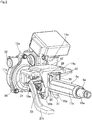
- the steering apparatus for an automobile of this example comprises a steering column 6a, a steering shaft 5a, a housing 11a for an electric power steering apparatus 10a, a vehicle-side bracket 19a and an expansion and contraction mechanism 29.
- the steering column 6a comprises an outer column 18a that is a front column, and an inner column 17a that is a rear column, that are combined so as to be capable of relative displacement in the axial direction.
- the outer column 18a is formed by using a press to perform punching or bending of a metal plate material such as carbon steel plate having sufficient strength and rigidity, and is formed into a U shape that is open at the top comprising a pair of left and right side plate sections 30, the inside surface of which face each other, and a bottom plate section 31 that is connected to the edges on the bottom ends of these side plate sections 30.
- both end sections in the width direction of the bottom plate section 31 are inclined at 45 degrees with respect to both the center section in the width direction of the bottom plate section and the side plate sections 30.
- the dimension in the up-down direction of the side plate sections 30 is comparatively large on the rear-end section and comparatively small on the front-end section, and in the portion between the rear-end section and the front-end section, the dimension changes so as to become smaller going toward the front-end side.
- the bending rigidity of the side plate sections 30 is maintained by forming a plurality of stiffening beads in both the rear-end section and the middle section of the side plate sections 30, and by forming a flange-like section by bending the top end of the middle section 90 degrees toward the outside in the horizontal direction.
- restraining blocks 32 are fastened to the portion near the top end of the rear-end section of the inside surfaces of the side plate sections 30 by bolts, welding or the like.
- the bottom surfaces of these restraining blocks 32 are also inclined 45 degrees with respect to the side plate sections 30 and the center section in the width direction of the bottom plate section 31.
- the portion that is surrounded by the inside surfaces of the side plate sections 30, the top surface of the bottom plate section 31 and the bottom surface of the restraining blocks 32 is such that the center section in the width direction is open toward the top, and forms nearly an octagonal shaped holding space.
- the inner column 17a is formed by performing desired plastic working or milling on the end section of an intermediate material that is integrally formed by extrusion or drawing of a metal material containing a light alloy such as an aluminum alloy, magnesium alloy or the like.
- the outer perimeter surface of the inner column is an octagonal shape.
- the front section of this inner column 17a fits inside the rear section of the outer column 18a such that the forward-backward position is adjustable according to displacement in the axial direction.
- the entire steering column can be formed into an arbitrary column shape, and only the front end section is formed into a U shape that is open at the top end by a pair of left and right side plate sections that face each other and a bottom plate section that connects the edges on the bottom ends of the side plate sections.
- the steering shaft 5a is such that by combining the rear section of the inner shaft 15a on the front side and the front section of the outer shaft 16 on the rear by a spline fit, the inner shaft 15a and the outer shaft 16a are capable of transmitting rotation force, and are capable of relative displacement in the axial direction. With this construction, the entire length of the steering shaft 5a is able to expand and contract.
- the steering shaft 5a passes through the inside of the steering column 6a, and the portion near the rear end of the outer shaft 16a is supported by the rear-end section of the inner column 17a by a bearing such as a single-row deep-groove ball bearing that is capable of supporting both radial loads and thrust loads so that steering shaft 5a can rotate freely.
- a bearing such as a single-row deep-groove ball bearing that is capable of supporting both radial loads and thrust loads so that steering shaft 5a can rotate freely.
- the top surface of the housing 11a for the electric power steering apparatus 10a supports an electric motor 14a, which is the auxiliary driving source. Moreover, the housing 11a houses a plurality of component parts including a reduction gear 34 for transmitting the rotation driving force of the electric motor 14a to the steering shaft 5a. Furthermore, a support tube 35 is provided in the left-right direction at the top end section at the front of the housing 11a.
- the housing 11a is supported by the vehicle body such that it can pivotally displace around a horizontal shaft such as a bolt that is inserted through the support tube. With this construction, the steering shaft 5a to which the steering wheel is fastened to the rear-end section, and the steering column 6a that supports the steering shaft 5a are able to displace in the up-down direction. Therefore, in construction that does not comprise a tilt mechanism the housing 11a can be supported by and fastened to the vehicle body by rigid construction.
- the front-end section of the outer column 18a is connected and fastened to the rear-end section of the housing 11a.
- a rectangular block shaped connecting and fastening section 36 is provided in the center section of the rear-end surface of the housing 11a.
- a center hole (not illustrated in the figures) is formed in the center of this connecting and fastening section 36, a pair of slits 37 that are parallel with each other are formed in the portions near the left and right ends of the connecting and fastening section 36, and openings are formed in bottom-end surface and the rear-end surface of the connecting and fastening section 36.
- the shape of the connecting and fastening section 36 can be another shape such as a semi-circular shape as long as it is possible to form a pair of slits 37 in the portions near the left and right ends.
- construction is used in which the front-end section of the side plate sections 30 of the outer column 18a can be pressed into the slits 37 through openings on the bottom ends of these slits 37.
- the portion of the connecting and fastening section 36 that is between the slits 37 can be pressed inside the front-end section of the outer column 18a through the opening in the top end of the front-end section.
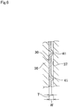
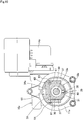
- the front-end sections of the side plate sections 30 can be pressed inside the slits 37, so construction as illustrated in detail in FIG. 6 is used. That is, the width (W) of the slit 37 is greater than the plate thickness (T) of the side plate section 30 (W>T).
- the width (W) of the slits 37 is double the plate thickness (T) of the side plate sections 30 (W ⁇ 2T).
- the side surfaces of the side plate sections 30 are such that semi-spherical protrusions 41, which are protruding sections, are formed at a plurality of locations on the side surfaces of the sides of the side plate sections 30 that face each other.
- the portions of the side plate sections 30 where the protrusions 41 are formed are thicker than the width (W) of the slits 37, and the side plate sections 30 are inserted inside the slits 37 in a state with interference such that there is no movement, so it is possible to increase the rigidity of the connecting section between the connecting and fastening section 36 and the front-end section of the outer column 18a.
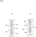
- bent raised pieces 57 as illustrated in FIG.9A instead of the semi-spherical protrusions 41 illustrated in FIG. 6 as the protruding sections that are formed on the side surfaces of the front-end section of the side plate sections 30.
- the bent raised pieces 57 are formed by making U-shaped cuts in part of the side plate sections 30 and bending the portions on the inside of those cuts in a direction protruding from one side surface of the side plate sections 30.
- FIG.9B illustrates an example of forming ridges 58 that are long in the forward-backward direction (front-rear direction in FIG.
- the protruding sections can be formed on both the side surfaces of the side plate sections 30 and the inside surfaces of the slits 37. In this case, by staggering the phase in the forward-backward direction of these protruding sections, interference between these protruding sections can be avoided when inserting the side plate sections 30 inside the slits 37.
- protruding sections can be formed by bending the shape of the side plate sections 30 so that the tip end sections are bent in the direction toward each other, or by fastening synthetic resin protrusions to the side surfaces of the side plate sections 30, thus enabling the front-end sections of the side plate sections 30 to be pressure fitted inside the slits 37.
- the center section in the width direction of the top surface of the front-end section of the bottom plate section 31 of the outer column 18a is brought into contact with the center section in the width direction of the bottom surface of the portion of the connecting and fastening section 36 that is between the slits 37.
- a fastening bolt 39 that is inserted through a though hole 38 that is formed in the center section in the width direction of the front-end section of the bottom plate section 31 is screwed into a screw hole 40 that is formed in the center section in the width direction of the bottom surface of the connecting and fastening section 36 and that is open on the bottom end surface, and by tightening the bolt, the connecting and fastening section 36 is connected and fastened to the front-end section of the outer column 18a.
- the assembly direction of the fastening bolt 39 and the assembly direction of the steering column 6a to the vehicle-side support bracket 19a are the same, and are in the radial direction of the steering column 6a (direction from the bottom surface toward the top surface).
- the front-end sections of the side plate sections 30 of the outer column 18a can be pressure fitted inside the slits 37, and thus the ease of assembly of the steering apparatus can be improved.
- the front-end sections of the side plate sections 30 of the outer column 18a are prevented from coming out of the slits 37 even when the body of the operator collides with the steering wheel 1 (see FIG. 11 ) during a secondary collision, and the entire steering apparatus rotates around the expansion and contraction mechanism 29 such that the front side rotates downward and the rear side rotates upward (counterclockwise direction in FIG. 3 ).
- the front-end section of the inner shaft 15a is inserted inside the housing 11a through a center hole (not illustrated in the figure) in the connecting and fastening section 36, and connects with the component parts of the electric power steering apparatus 11a that is housed inside the housing 11a.
- the vehicle-side bracket 19a comprises a top plate section 42 and a pair of holding plate sections 20a, 20b.
- the top plate section 42 and holding plate sections 20a, 20b are formed by using a press to perform punching and bending of a metal plate such as steel plate having sufficient strength and rigidity, and connected and fastened together to form a single piece by welding or the like. Installation holes, through which bolts or studs are passed in order to support the top plate section 42 and fasten the top plate section 42 to the vehicle body, are formed in the top plate section 42.
- holding plate sections 20a, 20b are placed at positions on both sides in the left-right direction of the rear-end section of the outer column 18a.
- Long holes 22a, 22b that are long in the up-down direction are formed at positions in the top portions of the holding plate sections 20a, 20b that are aligned with each other.
- the long holes 22a, 22b in the up-down direction are arc shaped around the center axis of the support tube 35.
- an energy-absorbing member 28 which is a member of the inner column 17a, is fastened to the top surface of the front-end section of the inner column 17a.
- This energy-absorbing member is formed by bending a metal plate, such as mild steel plate that is capable of plastic deformation, into a long rectangular frame shape that is long in the forward-backward direction, and an installation plate section 43 protrudes forward from the bottom-end section of the front-end surface.
- Installation members 44 such as rivets or screws that are inserted through holes that are formed in this installation plate section 43 fasten the energy-absorbing member 28 to the inner column 17a.
- This energy-absorbing member 28 expands due to plastic deformation that occurs during a secondary collision that accompanies a collision accident, and allows the inner column 17a to displace in the forward direction together with the steering wheel. As a result, it is possible to protect the operator by absorbing energy that is transmitted from the body of the operator to the inner column 17a by way of the steering wheel during a secondary collision.
- the expansion and contraction mechanism 29 is form expanding or contracting the space between the inside surfaces of the holding plate sections 20a, 20b, and comprises an adjustment rod 24a, which is a rod shaped member, an adjustment lever 27a, and a cam device 45.
- the adjustment rod 24a is inserted in the left-right direction through the long holes 22a, 22b in the up-down direction, through holes 46 that are formed in the side plate sections 30 and restraining blocs 32 of the outer column 18a, and long hole 23a in the forward-backward direction that is long in the axial direction of the inner column 17a and formed in the inside of the energy-absorbing member that is attached to the inner column 17a.
- the rod section 24a is such that a head section 25a is formed on the base end section (right end section in FIG. 4 and FIG. 8 ), and a convex section that is formed on the inside surface of this head section 25a fits inside one of the long holes 22a in the up-down direction that is formed on one of the holding plate section 20a of the holding plate sections 20a, 20b (right holding plate section in FIG. 4 and FIG. 8 ) so as to be able to displace (move up or down) only along this long hole 22a in the up-down direction.
- the adjustment lever 27a is such that the base end section is supported by the tip end section (left end section of FIG. 4 and FIG.
- the long hole 23a in the forward-backward direction can also be formed in the inner column 17a itself, or can be formed in a separate member that is attached to the inner column 17a.
- the cam device 45 is provided between the inside surface on the base end section of the adjustment lever 27a and the outside surface of the other holding plate section 20b of the holding plate sections 20a, 20b (left holding plate section in FIG. 4 and FIG. 8 ).
- the cam device 45 comprises a driving cam 49 that is supported by the inside surface of the base end section of the adjustment lever 27a and that rotates together with the adjustment lever, and a driven cam 50 that fits in the other long hole 22b in the up-down direction that is formed in the other holding plate section 20b so as to be able to move only up or down.
- Cam surfaces are formed on the surfaces of the driven cam 50 and the driving cam 49 that face each other, and due to relative rotation between the driven cam 50 and driving cam 49, the dimension in the axial direction of the cam device 45 expands or contracts.
- the head section 25a and the driven cam 50 form a pair of pressing sections.
- Spacers 51a, 51b which are formed using a material such as synthetic resin that slides easily, are placed over positions in the middle section of the adjustment rod 24a that are located on the inside of the long holes 22a, 22b in the up-down direction, making it possible for the adjustment rod 24a to smoothly displace along the long holes 22a, 22b in the up-down direction.
- a cylindrical radial sliding bearing 52 that is made using a material that slides easily is located between the inner circumferential surface of the driving cam 49 and the outer circumferential surface of the adjustment rod 24a.
- the dimension in the axial direction of the cam device 45 is shortened by rotating the adjustment lever 27a in the downward direction.
- the space between the inside surfaces of the holding plate sections 20a, 20b is expanded and the surface pressure at the area of contact between the inside surfaces of these holding plate sections 20a, 20b and the outside surfaces of the side plate sections 30 of the outer column 18a is sufficiently reduced.
- the space between the side plate sections 30 and the restraining blocks 32 is expanded, and the surface pressure at the area of contact between the outer circumferential surface of the inner column 17 and inner circumferential surface of the outer column 18a is sufficiently reduced.
- the state of the outer column 18a and inner column 17a being fastened to the vehicle-side bracket 19a is released.
- the steering column 6a and the steering shaft 5a are pivoted around the support tube 35 within the range that the adjustment rod can displace inside the long holes 22a, 22b in the up-down direction.
- construction is provided for increasing the support strength for supporting the steering wheel in the adjusted up-down position.
- the base section of a pivot arm 53 is fitted over the portion of the adjustment rod 24a near the tip end of the middle section so as to be able to pivot and displace.
- a male gear 54 is provided on the tip end section of the pivot arm 53 and a female gear 55 is provided on part of the outside surface of the holding plate section 20b, and as the pivot arm 53 pivots, the male gear 54 and female gear 55 can be placed in either the engaged state or released state.
- the adjustment lever 27a is rotated in a direction for adjusting the position of the steering wheel, the pivot arm 53 is pivoted in a direction that releases the engagement between the male gear 54 and the female gear 55.
- the adjustment rod 24a is connected with the holding plate section 20b by way of the pivot arm 53, so regardless of whether there is a large impact load during a secondary collision, the up-down position of the steering wheel does not move a large amount.
- the driven cam 50 is assembled to the base section of the pivot arm 53 so as to be able to rotate relative to the pivot arm 53 as well as to be able to displace a little in the up-down direction with respect to the pivot arm 53.
- the driven cam 50 as described above, is such that relative rotation with respect to the holding plate section 20b is prevented.
- a restoring spring 56 is provided between the driven cam 50 and the pivot arm 53, and supports the driven cam 50 with respect to the pivot arm 53 so as to be able move up or down a little about the neutral position.
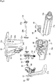
- the assembly direction of the steering column 6a in the vehicle-side bracket 19a coincide with the assembly direction of the steering column 6a in the housing 11a.
- the middle portion of the steering column 6a (rear-end section of the outer column 18a) is inserted between the pair of holding plate sections 20a, 20b of the vehicle-side bracket 19a from the bottom end edge side of these holding plate sections 20a, 20b. That is, the assembly direction of the steering column 6a with respect to the vehicle-side bracket 19a is in the radial direction of the steering column 6a (direction from the bottom surface toward the top surface).
- the front-end sections of the part of side plate sections 30 of the outer column 18a are inserted into the pair of slits 37, which are formed in a connection and fastening section 36 that is provided on the rear-end section of the housing 11a, by way of openings on the bottom ends of these slits 37. That is, the assembly direction of the steering column 6a with respect to the housing 11a can also be in the radial direction of the steering column 6a (direction from the bottom surface toward the top surface).
- the housing 11a and the vehicle-side bracket 19a are set in a tool with the positional relationship illustrated in FIG. 7 , and in this state, the front-end section and the middle section of the steering column 6a can be assembled into the connection and fastening section 36 of the housing 11a and the pair of holding plate sections 20a, 20b of the vehicle-side bracket 19a in the radial direction of the steering column 6a from the bottom in FIG. 7 . Therefore, assembling the steering column 6a in the vehicle-side support bracket 19a and assembling the steering column 6a in the housing 11a can be performed in one process, and thus it is possible to improve the ease of assembly of the steering apparatus by that amount. The actual work is performed in a positional relationship that is upside down from the positional relationship illustrated in FIG. 7 .
- the work of inserting the front-end section of the steering column 6a (front-end sections of the side plate sections 30) into the slits 37, and the work of inserting the middle section of the steering column 6a into the portion between the holding plate sections 20a, 20b can be performed in order as described below.
- the housing 11a and the vehicle-side support bracket 19a are set in a too with the positional relationship illustrated in FIG. 7 , then only the housing 11a is pivoted and displaced around the support tube 35 toward the bottom in FIG. 7 .
- the front-end section of the steering column 6a (front-end sections of the side plate sections 30) is inserted into the slits 37 through openings on the bottom ends of these slits 37.
- the housing 11a and the steering column 6a are pivoted and displaced around the support tube 35 toward the top in FIG. 7 , and the middle section of the steering column 6a is inserted into the portion between the holding plate sections 20a, 20b.
- the phase in the rotational direction of the steering column 6a is in the proper phase, and this proper phase is maintained, so it becomes easy to perform the following insertion work.
- the two insertions described above can be performed in one process on an assembly line for the steering apparatus.
- the work of inserting the front-end section of the steering column 6a (front-end sections of the side plate sections 30) into the slits 37 through the openings on the bottom ends of the slits 37 is performed in a state wherein the steering shaft 5a is not placed inside the steering column 6a, or is performed in a state wherein the front-end section of the steering shaft 5a that has been placed inside the steering column 6a is moved sufficiently out of the way toward the rear. In this way, the front-end section of the steering shaft 5a is prevented from hindering the insertion work.
- a screw hole 59 is formed as a through hole in the width direction (left-right direction in FIG 10 ) in the portion near the top end of the connection and fastening section 36a that is formed in the center section of the rear-end surface of the housing 11a.
- a female screw section 60 is formed in just the port near one end in the width direction (near the right end in FIG. 10 ) of the inner circumferential surface of the screw hole 59, and the other portion is formed as simply a through hole.
- through holes 61 that pass in the width direction through the pair of side plate sections 30 of the outer column 18a at positions that are aligned with the screw hole 59 in the connection and fastening section 36a.
- the front-end sections of the side plate sections 30 of the outer column 18a are inserted inside the pair of slits 37 in the connection and fastening section 36a through openings in the bottom end of the slits 37.
- the male screw section 63 of a bolt 62 that is passed through the screw hole 59 in the connection and fastening section 36a and the through holes 61 in the side plate sections 30 from one side in the width direction (left side in FIG. 10 ) to the other side (right side in FIG. 10 ) is screwed into the female screw section 60 in the connection and fastening section 36a and further tightened.
- connection and fastening section 36a that is further on the outside in the width direction than the slits 37 is tightened so as to contract toward the inside in the width direction.
- construction can be applied wherein a fastening bolt 39 that is passed through a through hole 38 that is formed in the center section in the width direction of the front-end section of the bottom plate section 31 of the outer column 18a is screwed into a screw hole 40 that is formed in the center section in the width direction on the bottom surface of the connecting and fastening section 36a, and by further tightening, the connection and fastening section 36 is connected and fastened to the front-end section of the outer column 18a.
- construction is applied as illustrated in FIG. 6 in order that the front-end sections of the side plate sections 30 can be inserted inside the slits 37.
- the construction and function of other parts are the same as those in the case of the first example of the embodiment.
- the bolt 62 is tightened so that the portions of the connection and fastening member 36a that are further on the outside in the width direction than the slits are contracted toward the inside in the width direction (side of the side plate sections 30). Therefore, the surface pressure at the areas of contact between the inside surfaces of the slits 37 and the surfaces of both sides in the width direction of the side plate sections 30 increases, and thus it is possible to improve the rigidity of the connecting section between the outer column 18a and the connection and fastening member 36a.
- the bolt 62 connects and fastens the connecting and fastening section 36a and outer column 18a, so the side plate sections 30 of the outer column are effectively prevented from coming out from the slits 37 even when body of the operator collides with the steering wheel 1 (see FIG. 11 ) during a secondary collision and the entire steering apparatus rotates about the expansion and contraction mechanism 29 so that the front side rotates downward and the rear side rotates upward (counterclockwise direction in FIG. 3 ).
- the present invention is applied to construction that comprises both a tilt mechanism for making it possible to adjust the up-down position of the steering wheel, and a telescopic mechanism for making it possible to adjust the forward-backward position of the steering wheel.
- the present invention can also be applied to construction that comprises only one of these mechanisms.
Landscapes
- Engineering & Computer Science (AREA)
- Chemical & Material Sciences (AREA)
- Combustion & Propulsion (AREA)
- Transportation (AREA)
- Mechanical Engineering (AREA)
- Steering Controls (AREA)
- Power Steering Mechanism (AREA)
Claims (8)
- Appareil de direction pour une automobile comprenant :une colonne de direction (6a) comprenant : une colonne avant (18a) qui est située sur le côté avant, et une colonne arrière (17a) qui est située sur le côté arrière et assemblée de manière à être apte à se déplacer par rapport à la colonne avant (18a), la colonne de direction (6a) supportant un arbre de direction (5a) sur l'intérieur de celle-ci ;un logement (11a) pour un appareil de direction à puissance électrique (10a) qui est supporté par la carrosserie de véhicule (12) ;un support côté véhicule (19a) qui est supporté par la carrosserie de véhicule (12) et qui a une paire de sections formant plaque de retenue (20a, 20b) qui sont situées au niveau de positions sur les deux côtés gauche et droit de la section médiane de la colonne de direction (6a), avec la partie qui existe entre les bords inférieurs qui est composée des sections formant plaque de retenue (20a, 20b) qui est ouverte ; etun mécanisme d'expansion et de contraction (29) qui comprend un élément en forme de tige (24a) qui est inséré dans la direction gauche-droite à travers un trou traversant (22a, 22b) qui est formé dans des positions des sections formant plaque de retenue (22a, 22b) qui sont alignées l'une avec l'autre, et une paire de sections de compression (25a, 50) qui sont prévues sur les deux sections d'extrémité de l'élément en forme de tige (24a), et en écartant ces sections de compression (25a, 50) l'une de l'autre ou en les rapprochant l'une de l'autre dans la direction axiale de l'élément en forme de tige (24a), l'espace entre les sections formant plaque de retenue (20a, 20b) est modifié, et lorsque cet espace est contracté, le mécanisme d'expansion et de contraction (29) fixe la colonne de direction (6a) à ces sections formant plaque de retenue (20a, 20b) ;caractérisé en ce quela colonne avant de la colonne de direction (6a) a une section d'extrémité avant qui est façonnée en une forme de U qui est ouverte sur le dessus et comprend une paire de sections formant plaque latérale gauche et droite (30) qui se font face et une section formant plaque inférieure (31) qui se raccorde aux bords sur les extrémités inférieures de ces sections formant plaque latérale (30),le logement (11a) a une section de raccordement et de fixation (36, 36a) sur l'arrière, la section de raccordement et de fixation (36, 36a) comprenant un trou central qui est formé dans le centre de celle-ci et à travers lequel la section d'extrémité avant de l'arbre de direction (5a) est insérée à l'intérieur du logement (11a), et une paire de fentes gauche et droite (37) qui sont parallèles l'une à l'autre, qui sont formées dans les parties près des extrémités gauche et droite de la section de raccordement et de fixation (36, 36a), et qui ont des ouvertures sur la surface d'extrémité inférieure et la surface d'extrémité arrière qui reçoivent les sections formant plaque latérale (30) sur la section d'extrémité avant de la colonne de direction (6a), etavec les sections formant plaque latérale (30) de la section d'extrémité avant qui sont insérées dans les fentes (37) de la section de raccordement et de fixation (36, 36a), la section d'extrémité avant et la section de raccordement et de fixation (36, 36a) sont raccordées et fixées ensemble par un boulon (39, 62).
- Appareil de direction pour une automobile selon la revendication 1, dans lequel une construction (41, 57, 58) au moyen de laquelle la section d'extrémité avant des sections formant plaque latérale (30) de la colonne externe (18a) peuvent être comprimées dans les fentes (37) est formée sur au moins une des fentes (37) et des sections formant plaque latérale (30).
- Appareil de direction pour une automobile selon la revendication 1, dans lequel des sections saillantes (41) sont formées sur au moins une surface latérale des fentes (37) dans la section de raccordement et de fixation (36, 36a) et les sections formant plaque latérale (30) de la section d'extrémité avant, et avec les sections formant plaque latérale (30) de la section d'extrémité avant qui sont insérées dans les fentes (37) de la section de raccordement et de fixation (36a), les sections saillantes (41) viennent en contact élastique avec la surface opposée qui fait face à l'une surface latérale.
- Appareil de direction pour une automobile selon la revendication 1, dans lequel un trou de vis (40) qui est ouvert sur la surface d'extrémité inférieure est formé dans une position de la section de raccordement et de fixation (36, 36a) qui est entre les fentes (37), un trou traversant (38) est formé dans une position de la section formant plaque inférieure (31) de la section d'extrémité avant qui est alignée avec le trou de vis (40), et avec la surface supérieure de la section formant plaque inférieure (31) de la section d'extrémité avant en contact avec la surface d'extrémité inférieure de la section de raccordement et de fixation (36, 36a), et avec un boulon (39) inséré à travers le trou traversant (38) dans la section formant plaque inférieure (31), le boulon (39) est vissé dans le trou de vis (40).
- Appareil de direction pour une automobile selon la revendication 1, dans lequel un trou de vis (59) est formé de manière à passer dans la direction gauche-droite à travers la partie près de l'extrémité supérieure de la section de raccordement et de fixation (36a) au moyen des fentes (37), des trous traversants (61) sont formés dans les sections formant plaque latérale (30) de la section d'extrémité avant au niveau de positions qui sont alignées avec le trou de vis (59), et avec la surface supérieure de la section formant plaque inférieure (31) de la section d'extrémité avant en contact avec la surface d'extrémité inférieure de la section de raccordement et de fixation (36a), et avec un boulon (62) inséré à travers les trous traversants (61) dans les sections formant plaque latérale (30), le boulon (62) est vissé dans le trou de vis (59).
- Appareil de direction pour une automobile selon la revendication 1, dans lequel
le logement (11a) est supporté par la carrosserie de véhicule (12) de manière à être apte à se déplacer de manière pivotante autour d'un arbre horizontal (13, 35) qui est agencé dans la direction gauche-droite ;
des trous traversants dans les sections formant plaque de retenue (20a, 20b) sont des trous longs dans la direction haut-bas (22a, 22b) qui sont en forme d'arc autour du centre de l'arbre horizontal (18, 35) ;
un trou traversant (46) est formé dans la section arrière de la colonne avant (18a) au niveau d'une position qui est alignée avec les trous longs dans la direction haut-bas (22a, 22b) ;
l'élément en forme de tige (24a) est inséré à travers les trous longs dans la direction haut-bas (22a, 22b) du logement et le trou traversant (46) de la colonne avant (18a) ; et
lorsque l'état fixé de la colonne de direction (6a) qui est fixée aux sections formant plaque de retenue (20a, 20b) est libéré en augmentant l'espace entre les sections formant plaque de retenue (20a, 20b) par le mécanisme d'expansion et de contraction (29), la position haut-bas de la colonne de direction (6a) peut être ajustée au sein de la plage dans laquelle l'élément en forme de tige (24a) peut se déplacer dans les trous longs dans la direction haut-bas (22a, 22b). - Appareil de direction pour une automobile selon la revendication 1, dans lequel
un trou traversant (46) est formé dans la section arrière de la colonne avant (18a) au niveau d'une position qui est alignée avec des trous traversants (22a, 22b) dans les sections formant plaque de retenue (20a, 20b) ;
un trou long dans la direction vers l'avant-vers l'arrière (23a) qui est long dans la direction axiale de la colonne arrière (17a) est formé dans la colonne arrière (17a) au niveau d'une position qui est alignée avec les trous traversants (22a, 22b) dans les sections formant plaque de retenue (20a, 20b) et le trou traversant (46) dans la colonne avant (18a) ;
l'élément en forme de tige (24a) est inséré à travers les trous traversants (22a, 22b) dans les sections formant plaque de retenue (20a, 20b), le trou traversant (46) dans la colonne avant (18a) et le trou long dans la direction vers l'avant-vers l'arrière (23a) de la colonne arrière (17a), et lorsque l'état fixé entre la colonne arrière (17a) et les sections formant plaque de retenue (20a, 20b) et la colonne avant (18a) est libéré en agrandissant l'espace entre les sections formant plaque de retenue (20a, 20b) par le mécanisme d'expansion et de contraction (29), il est possible d'ajuster la position vers l'avant-vers l'arrière de la colonne arrière (17a) au sein d'une plage dans laquelle l'élément en forme de tige (24a) peut se déplacer à l'intérieur du trou long dans la direction vers l'avant-vers l'arrière (23a). - Appareil de direction (10a) pour une automobile selon la revendication 7, dans lequel
la colonne avant est une colonne externe (18a), et cette colonne externe (18a) entière est formée en pratiquant un emboutissage ou une courbure d'un matériau en plaque métallique en une forme de U qui est ouverte sur le haut avec les sections formant plaque latérale (30) et la section formant plaque inférieure (31) ;
la colonne arrière est une colonne interne (17a) et est telle que la section avant de cette colonne interne (17a) s'adapte à l'intérieur de la section arrière de la colonne externe (18a) ;
le mécanisme d'expansion et de contraction (29) étend ou contracte la dimension interne de la section arrière de la colonne externe (18a) en modifiant l'espace entre les sections formant plaque de retenue (20a, 20b), de telle sorte que lorsque la dimension interne est contractée, un déplacement dans la direction axiale de la colonne interne (17a) par rapport à la colonne externe (18a) est supprimé, et lorsque la dimension interne est étendue, un déplacement dans la direction axiale de la colonne interne (17a) par rapport à la colonne externe (18a) est possible.
Applications Claiming Priority (2)
| Application Number | Priority Date | Filing Date | Title |
|---|---|---|---|
| JP2011111581 | 2011-05-18 | ||
| PCT/JP2012/062650 WO2012157702A1 (fr) | 2011-05-18 | 2012-05-17 | Appareil de direction pour véhicule automobile |
Publications (3)
| Publication Number | Publication Date |
|---|---|
| EP2711264A1 EP2711264A1 (fr) | 2014-03-26 |
| EP2711264A4 EP2711264A4 (fr) | 2015-12-09 |
| EP2711264B1 true EP2711264B1 (fr) | 2018-08-15 |
Family
ID=47177019
Family Applications (1)
| Application Number | Title | Priority Date | Filing Date |
|---|---|---|---|
| EP12733583.4A Active EP2711264B1 (fr) | 2011-05-18 | 2012-05-17 | Appareil de direction pour vehicule automobile |
Country Status (5)
| Country | Link |
|---|---|
| US (1) | US8997600B2 (fr) |
| EP (1) | EP2711264B1 (fr) |
| JP (1) | JP5626346B2 (fr) |
| CN (1) | CN102958779B (fr) |
| WO (1) | WO2012157702A1 (fr) |
Families Citing this family (10)
| Publication number | Priority date | Publication date | Assignee | Title |
|---|---|---|---|---|
| EP2915721B1 (fr) * | 2013-01-30 | 2018-10-03 | NSK Ltd. | Colonne de direction |
| JP5886805B2 (ja) * | 2013-09-03 | 2016-03-16 | 株式会社山田製作所 | ステアリング装置 |
| FR3029489B1 (fr) * | 2014-12-09 | 2018-06-15 | Zf Systemes De Direction Nacam S.A.S. | Mecanisme de colonne de direction ajustable en profondeur a butee escamotable |
| US9834245B2 (en) * | 2014-12-18 | 2017-12-05 | Nsk Ltd. | Steering device |
| DE102015000028A1 (de) * | 2015-01-08 | 2016-07-14 | Thyssenkrupp Ag | Fertigungsverfahren für eine modulare Lenksäule mit Strangpressprofilen |
| JP6527001B2 (ja) * | 2015-03-31 | 2019-06-05 | 富士機工株式会社 | ステアリングコラム装置 |
| CN104908805B (zh) * | 2015-06-26 | 2018-09-14 | 株洲易力达机电有限公司 | 一种管柱助力式电动助力转向器 |
| WO2017057158A1 (fr) * | 2015-09-29 | 2017-04-06 | 日本精工株式会社 | Appareil de réglage de position d'un volant |
| DE102015220934B3 (de) * | 2015-10-27 | 2016-11-24 | Thyssenkrupp Ag | Lenksäule für ein Kraftfahrzeug und Verfahren zur Herstellung einer Lenksäule |
| JP6777229B2 (ja) | 2017-06-14 | 2020-10-28 | 日本精工株式会社 | ステアリングコラム装置 |
Family Cites Families (22)
| Publication number | Priority date | Publication date | Assignee | Title |
|---|---|---|---|---|
| JPH11291919A (ja) * | 1998-04-07 | 1999-10-26 | Nippon Seiko Kk | 電動パワーステアリング装置 |
| JP3763337B2 (ja) * | 1998-09-16 | 2006-04-05 | 株式会社ジェイテクト | 電動式舵取装置 |
| DE19983199T1 (de) * | 1998-09-25 | 2002-02-28 | Douglas Autotech Corp | Lenkrad-Positionierungssystem für den Kollisionsfall |
| JP3725762B2 (ja) * | 2000-05-25 | 2005-12-14 | 光洋精工株式会社 | 衝撃吸収式電動パワーステアリング装置 |
| CN2431654Y (zh) * | 2000-05-31 | 2001-05-23 | 莫列斯公司 | 连接器端子改良结构 |
| CN2432700Y (zh) * | 2000-07-28 | 2001-05-30 | 富士康(昆山)电脑接插件有限公司 | 电连接器 |
| JP2002302046A (ja) | 2001-04-09 | 2002-10-15 | Koyo Seiko Co Ltd | ステアリング装置 |
| JP4069362B2 (ja) | 2002-07-05 | 2008-04-02 | 日本精工株式会社 | ステアリングコラム装置 |
| US7090250B2 (en) * | 2002-09-25 | 2006-08-15 | Fuji Kiko Co., Ltd. | Steering system with tilt control |
| JP4699212B2 (ja) * | 2003-09-25 | 2011-06-08 | 日本精工株式会社 | 電動パワーステアリング装置 |
| US8056437B2 (en) * | 2005-04-19 | 2011-11-15 | Nexteer (Beijing) Technology Co., Ltd. | Electric steering column lock with single direction actuator travel |
| CN101171165A (zh) * | 2005-05-06 | 2008-04-30 | 日本精工株式会社 | 转向柱装置 |
| JP2008087583A (ja) * | 2006-09-29 | 2008-04-17 | Nsk Ltd | ステアリング装置及びステアリング装置の組立方法 |
| US7665767B2 (en) * | 2007-03-08 | 2010-02-23 | Gm Global Technology Operations, Inc. | Collapsible steering column assembly |
| US7882761B2 (en) * | 2008-01-05 | 2011-02-08 | Nexteer (Beijing) Technology Co., Ltd. | Adjustable steering column assembly with compressive locking mechanism |
| US7685903B2 (en) * | 2008-05-19 | 2010-03-30 | Gm Global Technology Operations, Inc. | Dual on-center column lock mechanism |
| JP2011046309A (ja) * | 2009-08-27 | 2011-03-10 | Jtekt Corp | 車両用操舵装置 |
| DE102011000319B3 (de) * | 2011-01-25 | 2012-05-24 | Thyssenkrupp Presta Ag | Feststelleinrichtung zum Feststellen einer Lenkspindellagereinheit |
| US8770058B2 (en) * | 2011-06-03 | 2014-07-08 | Steering Solutions Ip Holding Corporation | System and method for fixing a position of a steering column |
| GB201109750D0 (en) * | 2011-06-10 | 2011-07-27 | Trw Ltd | A collapsible steering column assembly |
| GB201110277D0 (en) * | 2011-06-17 | 2011-08-03 | Trw Ltd | A clamp assembly for a steering column assembly |
| EP2765057B1 (fr) * | 2011-09-29 | 2017-05-17 | NSK Ltd. | Dispositif de direction télescopique |
-
2012
- 2012-05-17 EP EP12733583.4A patent/EP2711264B1/fr active Active
- 2012-05-17 JP JP2012523762A patent/JP5626346B2/ja active Active
- 2012-05-17 WO PCT/JP2012/062650 patent/WO2012157702A1/fr not_active Ceased
- 2012-05-17 CN CN201280000342.2A patent/CN102958779B/zh active Active
- 2012-05-17 US US13/574,028 patent/US8997600B2/en active Active
Non-Patent Citations (1)
| Title |
|---|
| None * |
Also Published As
| Publication number | Publication date |
|---|---|
| EP2711264A1 (fr) | 2014-03-26 |
| JPWO2012157702A1 (ja) | 2014-07-31 |
| WO2012157702A1 (fr) | 2012-11-22 |
| JP5626346B2 (ja) | 2014-11-19 |
| US8997600B2 (en) | 2015-04-07 |
| EP2711264A4 (fr) | 2015-12-09 |
| US20130199328A1 (en) | 2013-08-08 |
| CN102958779A (zh) | 2013-03-06 |
| CN102958779B (zh) | 2015-07-08 |
Similar Documents
| Publication | Publication Date | Title |
|---|---|---|
| US9073567B2 (en) | Steering apparatus for an automobile | |
| EP2711264B1 (fr) | Appareil de direction pour vehicule automobile | |
| US8931804B2 (en) | Steering device | |
| US20070068311A1 (en) | Steering apparatus | |
| EP2607203B1 (fr) | Appareil de direction | |
| CN202624345U (zh) | 转向装置 | |
| US20120318092A1 (en) | Steering apparatus | |
| JP5229280B2 (ja) | 衝撃吸収式ステアリング装置 | |
| JP2012111494A (ja) | ステアリング装置 | |
| WO2014030713A1 (fr) | Dispositif de direction télescopique | |
| EP2915721B1 (fr) | Colonne de direction | |
| JP2014104871A (ja) | ステアリングコラム用支持装置 | |
| EP2765058A1 (fr) | Dispositif de colonne de direction | |
| JP5146474B2 (ja) | ステアリングコラム装置とその組立方法 | |
| JP5146407B2 (ja) | ステアリング装置 | |
| JP5082871B2 (ja) | 車両用ステアリング装置 | |
| JP2009096381A (ja) | ステアリング装置 |
Legal Events
| Date | Code | Title | Description |
|---|---|---|---|
| PUAI | Public reference made under article 153(3) epc to a published international application that has entered the european phase |
Free format text: ORIGINAL CODE: 0009012 |
|
| 17P | Request for examination filed |
Effective date: 20120719 |
|
| AK | Designated contracting states |
Kind code of ref document: A1 Designated state(s): AL AT BE BG CH CY CZ DE DK EE ES FI FR GB GR HR HU IE IS IT LI LT LU LV MC MK MT NL NO PL PT RO RS SE SI SK SM TR |
|
| DAX | Request for extension of the european patent (deleted) | ||
| RA4 | Supplementary search report drawn up and despatched (corrected) |
Effective date: 20151109 |
|
| RIC1 | Information provided on ipc code assigned before grant |
Ipc: B62D 1/18 20060101AFI20151103BHEP Ipc: B62D 5/04 20060101ALI20151103BHEP |
|
| GRAP | Despatch of communication of intention to grant a patent |
Free format text: ORIGINAL CODE: EPIDOSNIGR1 |
|
| STAA | Information on the status of an ep patent application or granted ep patent |
Free format text: STATUS: GRANT OF PATENT IS INTENDED |
|
| INTG | Intention to grant announced |
Effective date: 20180117 |
|
| GRAS | Grant fee paid |
Free format text: ORIGINAL CODE: EPIDOSNIGR3 |
|
| GRAJ | Information related to disapproval of communication of intention to grant by the applicant or resumption of examination proceedings by the epo deleted |
Free format text: ORIGINAL CODE: EPIDOSDIGR1 |
|
| GRAL | Information related to payment of fee for publishing/printing deleted |
Free format text: ORIGINAL CODE: EPIDOSDIGR3 |
|
| STAA | Information on the status of an ep patent application or granted ep patent |
Free format text: STATUS: REQUEST FOR EXAMINATION WAS MADE |
|
| GRAP | Despatch of communication of intention to grant a patent |
Free format text: ORIGINAL CODE: EPIDOSNIGR1 |
|
| STAA | Information on the status of an ep patent application or granted ep patent |
Free format text: STATUS: GRANT OF PATENT IS INTENDED |
|
| INTC | Intention to grant announced (deleted) | ||
| INTG | Intention to grant announced |
Effective date: 20180531 |
|
| INTG | Intention to grant announced |
Effective date: 20180531 |
|
| GRAA | (expected) grant |
Free format text: ORIGINAL CODE: 0009210 |
|
| STAA | Information on the status of an ep patent application or granted ep patent |
Free format text: STATUS: THE PATENT HAS BEEN GRANTED |
|
| AK | Designated contracting states |
Kind code of ref document: B1 Designated state(s): AL AT BE BG CH CY CZ DE DK EE ES FI FR GB GR HR HU IE IS IT LI LT LU LV MC MK MT NL NO PL PT RO RS SE SI SK SM TR |
|
| REG | Reference to a national code |
Ref country code: CH Ref legal event code: EP Ref country code: GB Ref legal event code: FG4D Ref country code: AT Ref legal event code: REF Ref document number: 1029402 Country of ref document: AT Kind code of ref document: T Effective date: 20180815 |
|
| REG | Reference to a national code |
Ref country code: IE Ref legal event code: FG4D |
|
| REG | Reference to a national code |
Ref country code: DE Ref legal event code: R096 Ref document number: 602012049795 Country of ref document: DE |
|
| REG | Reference to a national code |
Ref country code: NL Ref legal event code: MP Effective date: 20180815 |
|
| REG | Reference to a national code |
Ref country code: LT Ref legal event code: MG4D |
|
| REG | Reference to a national code |
Ref country code: AT Ref legal event code: MK05 Ref document number: 1029402 Country of ref document: AT Kind code of ref document: T Effective date: 20180815 |
|
| PG25 | Lapsed in a contracting state [announced via postgrant information from national office to epo] |
Ref country code: GR Free format text: LAPSE BECAUSE OF FAILURE TO SUBMIT A TRANSLATION OF THE DESCRIPTION OR TO PAY THE FEE WITHIN THE PRESCRIBED TIME-LIMIT Effective date: 20181116 Ref country code: SE Free format text: LAPSE BECAUSE OF FAILURE TO SUBMIT A TRANSLATION OF THE DESCRIPTION OR TO PAY THE FEE WITHIN THE PRESCRIBED TIME-LIMIT Effective date: 20180815 Ref country code: BG Free format text: LAPSE BECAUSE OF FAILURE TO SUBMIT A TRANSLATION OF THE DESCRIPTION OR TO PAY THE FEE WITHIN THE PRESCRIBED TIME-LIMIT Effective date: 20181115 Ref country code: NL Free format text: LAPSE BECAUSE OF FAILURE TO SUBMIT A TRANSLATION OF THE DESCRIPTION OR TO PAY THE FEE WITHIN THE PRESCRIBED TIME-LIMIT Effective date: 20180815 Ref country code: FI Free format text: LAPSE BECAUSE OF FAILURE TO SUBMIT A TRANSLATION OF THE DESCRIPTION OR TO PAY THE FEE WITHIN THE PRESCRIBED TIME-LIMIT Effective date: 20180815 Ref country code: LT Free format text: LAPSE BECAUSE OF FAILURE TO SUBMIT A TRANSLATION OF THE DESCRIPTION OR TO PAY THE FEE WITHIN THE PRESCRIBED TIME-LIMIT Effective date: 20180815 Ref country code: RS Free format text: LAPSE BECAUSE OF FAILURE TO SUBMIT A TRANSLATION OF THE DESCRIPTION OR TO PAY THE FEE WITHIN THE PRESCRIBED TIME-LIMIT Effective date: 20180815 Ref country code: NO Free format text: LAPSE BECAUSE OF FAILURE TO SUBMIT A TRANSLATION OF THE DESCRIPTION OR TO PAY THE FEE WITHIN THE PRESCRIBED TIME-LIMIT Effective date: 20181115 Ref country code: AT Free format text: LAPSE BECAUSE OF FAILURE TO SUBMIT A TRANSLATION OF THE DESCRIPTION OR TO PAY THE FEE WITHIN THE PRESCRIBED TIME-LIMIT Effective date: 20180815 Ref country code: IS Free format text: LAPSE BECAUSE OF FAILURE TO SUBMIT A TRANSLATION OF THE DESCRIPTION OR TO PAY THE FEE WITHIN THE PRESCRIBED TIME-LIMIT Effective date: 20181215 |
|
| PG25 | Lapsed in a contracting state [announced via postgrant information from national office to epo] |
Ref country code: AL Free format text: LAPSE BECAUSE OF FAILURE TO SUBMIT A TRANSLATION OF THE DESCRIPTION OR TO PAY THE FEE WITHIN THE PRESCRIBED TIME-LIMIT Effective date: 20180815 Ref country code: HR Free format text: LAPSE BECAUSE OF FAILURE TO SUBMIT A TRANSLATION OF THE DESCRIPTION OR TO PAY THE FEE WITHIN THE PRESCRIBED TIME-LIMIT Effective date: 20180815 Ref country code: LV Free format text: LAPSE BECAUSE OF FAILURE TO SUBMIT A TRANSLATION OF THE DESCRIPTION OR TO PAY THE FEE WITHIN THE PRESCRIBED TIME-LIMIT Effective date: 20180815 |
|
| PG25 | Lapsed in a contracting state [announced via postgrant information from national office to epo] |
Ref country code: EE Free format text: LAPSE BECAUSE OF FAILURE TO SUBMIT A TRANSLATION OF THE DESCRIPTION OR TO PAY THE FEE WITHIN THE PRESCRIBED TIME-LIMIT Effective date: 20180815 Ref country code: PL Free format text: LAPSE BECAUSE OF FAILURE TO SUBMIT A TRANSLATION OF THE DESCRIPTION OR TO PAY THE FEE WITHIN THE PRESCRIBED TIME-LIMIT Effective date: 20180815 Ref country code: IT Free format text: LAPSE BECAUSE OF FAILURE TO SUBMIT A TRANSLATION OF THE DESCRIPTION OR TO PAY THE FEE WITHIN THE PRESCRIBED TIME-LIMIT Effective date: 20180815 Ref country code: RO Free format text: LAPSE BECAUSE OF FAILURE TO SUBMIT A TRANSLATION OF THE DESCRIPTION OR TO PAY THE FEE WITHIN THE PRESCRIBED TIME-LIMIT Effective date: 20180815 Ref country code: CZ Free format text: LAPSE BECAUSE OF FAILURE TO SUBMIT A TRANSLATION OF THE DESCRIPTION OR TO PAY THE FEE WITHIN THE PRESCRIBED TIME-LIMIT Effective date: 20180815 Ref country code: ES Free format text: LAPSE BECAUSE OF FAILURE TO SUBMIT A TRANSLATION OF THE DESCRIPTION OR TO PAY THE FEE WITHIN THE PRESCRIBED TIME-LIMIT Effective date: 20180815 |
|
| REG | Reference to a national code |
Ref country code: DE Ref legal event code: R097 Ref document number: 602012049795 Country of ref document: DE |
|
| PG25 | Lapsed in a contracting state [announced via postgrant information from national office to epo] |
Ref country code: SK Free format text: LAPSE BECAUSE OF FAILURE TO SUBMIT A TRANSLATION OF THE DESCRIPTION OR TO PAY THE FEE WITHIN THE PRESCRIBED TIME-LIMIT Effective date: 20180815 Ref country code: DK Free format text: LAPSE BECAUSE OF FAILURE TO SUBMIT A TRANSLATION OF THE DESCRIPTION OR TO PAY THE FEE WITHIN THE PRESCRIBED TIME-LIMIT Effective date: 20180815 Ref country code: SM Free format text: LAPSE BECAUSE OF FAILURE TO SUBMIT A TRANSLATION OF THE DESCRIPTION OR TO PAY THE FEE WITHIN THE PRESCRIBED TIME-LIMIT Effective date: 20180815 |
|
| PLBE | No opposition filed within time limit |
Free format text: ORIGINAL CODE: 0009261 |
|
| STAA | Information on the status of an ep patent application or granted ep patent |
Free format text: STATUS: NO OPPOSITION FILED WITHIN TIME LIMIT |
|
| 26N | No opposition filed |
Effective date: 20190516 |
|
| PG25 | Lapsed in a contracting state [announced via postgrant information from national office to epo] |
Ref country code: SI Free format text: LAPSE BECAUSE OF FAILURE TO SUBMIT A TRANSLATION OF THE DESCRIPTION OR TO PAY THE FEE WITHIN THE PRESCRIBED TIME-LIMIT Effective date: 20180815 |
|
| REG | Reference to a national code |
Ref country code: CH Ref legal event code: PL |
|
| PG25 | Lapsed in a contracting state [announced via postgrant information from national office to epo] |
Ref country code: CH Free format text: LAPSE BECAUSE OF NON-PAYMENT OF DUE FEES Effective date: 20190531 Ref country code: LI Free format text: LAPSE BECAUSE OF NON-PAYMENT OF DUE FEES Effective date: 20190531 Ref country code: MC Free format text: LAPSE BECAUSE OF FAILURE TO SUBMIT A TRANSLATION OF THE DESCRIPTION OR TO PAY THE FEE WITHIN THE PRESCRIBED TIME-LIMIT Effective date: 20180815 |
|
| REG | Reference to a national code |
Ref country code: BE Ref legal event code: MM Effective date: 20190531 |
|
| PG25 | Lapsed in a contracting state [announced via postgrant information from national office to epo] |
Ref country code: LU Free format text: LAPSE BECAUSE OF NON-PAYMENT OF DUE FEES Effective date: 20190517 |
|
| PG25 | Lapsed in a contracting state [announced via postgrant information from national office to epo] |
Ref country code: TR Free format text: LAPSE BECAUSE OF FAILURE TO SUBMIT A TRANSLATION OF THE DESCRIPTION OR TO PAY THE FEE WITHIN THE PRESCRIBED TIME-LIMIT Effective date: 20180815 |
|
| PG25 | Lapsed in a contracting state [announced via postgrant information from national office to epo] |
Ref country code: IE Free format text: LAPSE BECAUSE OF NON-PAYMENT OF DUE FEES Effective date: 20190517 |
|
| PG25 | Lapsed in a contracting state [announced via postgrant information from national office to epo] |
Ref country code: BE Free format text: LAPSE BECAUSE OF NON-PAYMENT OF DUE FEES Effective date: 20190531 |
|
| PG25 | Lapsed in a contracting state [announced via postgrant information from national office to epo] |
Ref country code: PT Free format text: LAPSE BECAUSE OF FAILURE TO SUBMIT A TRANSLATION OF THE DESCRIPTION OR TO PAY THE FEE WITHIN THE PRESCRIBED TIME-LIMIT Effective date: 20181215 |
|
| PGFP | Annual fee paid to national office [announced via postgrant information from national office to epo] |
Ref country code: FR Payment date: 20200414 Year of fee payment: 9 |
|
| PGFP | Annual fee paid to national office [announced via postgrant information from national office to epo] |
Ref country code: GB Payment date: 20200506 Year of fee payment: 9 |
|
| PG25 | Lapsed in a contracting state [announced via postgrant information from national office to epo] |
Ref country code: CY Free format text: LAPSE BECAUSE OF FAILURE TO SUBMIT A TRANSLATION OF THE DESCRIPTION OR TO PAY THE FEE WITHIN THE PRESCRIBED TIME-LIMIT Effective date: 20180815 |
|
| PG25 | Lapsed in a contracting state [announced via postgrant information from national office to epo] |
Ref country code: HU Free format text: LAPSE BECAUSE OF FAILURE TO SUBMIT A TRANSLATION OF THE DESCRIPTION OR TO PAY THE FEE WITHIN THE PRESCRIBED TIME-LIMIT; INVALID AB INITIO Effective date: 20120517 Ref country code: MT Free format text: LAPSE BECAUSE OF FAILURE TO SUBMIT A TRANSLATION OF THE DESCRIPTION OR TO PAY THE FEE WITHIN THE PRESCRIBED TIME-LIMIT Effective date: 20180815 |
|
| GBPC | Gb: european patent ceased through non-payment of renewal fee |
Effective date: 20210517 |
|
| PG25 | Lapsed in a contracting state [announced via postgrant information from national office to epo] |
Ref country code: GB Free format text: LAPSE BECAUSE OF NON-PAYMENT OF DUE FEES Effective date: 20210517 |
|
| PG25 | Lapsed in a contracting state [announced via postgrant information from national office to epo] |
Ref country code: FR Free format text: LAPSE BECAUSE OF NON-PAYMENT OF DUE FEES Effective date: 20210531 |
|
| PG25 | Lapsed in a contracting state [announced via postgrant information from national office to epo] |
Ref country code: MK Free format text: LAPSE BECAUSE OF FAILURE TO SUBMIT A TRANSLATION OF THE DESCRIPTION OR TO PAY THE FEE WITHIN THE PRESCRIBED TIME-LIMIT Effective date: 20180815 |
|
| PGFP | Annual fee paid to national office [announced via postgrant information from national office to epo] |
Ref country code: DE Payment date: 20250402 Year of fee payment: 14 |