EP2711509A2 - Procédé et moteur à combustion interne permettant de rendre exploitable les rejets thermiques ou la chaleur géothermique - Google Patents
Procédé et moteur à combustion interne permettant de rendre exploitable les rejets thermiques ou la chaleur géothermique Download PDFInfo
- Publication number
- EP2711509A2 EP2711509A2 EP13002654.5A EP13002654A EP2711509A2 EP 2711509 A2 EP2711509 A2 EP 2711509A2 EP 13002654 A EP13002654 A EP 13002654A EP 2711509 A2 EP2711509 A2 EP 2711509A2
- Authority
- EP
- European Patent Office
- Prior art keywords
- cylinder
- piston
- heat
- transfer medium
- heat transfer
- Prior art date
- Legal status (The legal status is an assumption and is not a legal conclusion. Google has not performed a legal analysis and makes no representation as to the accuracy of the status listed.)
- Withdrawn
Links
- 238000000034 method Methods 0.000 title claims abstract description 11
- 239000002918 waste heat Substances 0.000 title description 8
- 239000007788 liquid Substances 0.000 claims abstract description 21
- 238000002347 injection Methods 0.000 claims abstract description 8
- 239000007924 injection Substances 0.000 claims abstract description 8
- 238000001816 cooling Methods 0.000 claims description 10
- 239000002826 coolant Substances 0.000 claims description 6
- 239000003507 refrigerant Substances 0.000 claims description 2
- 238000005507 spraying Methods 0.000 claims 3
- 238000007599 discharging Methods 0.000 claims 1
- 230000002093 peripheral effect Effects 0.000 claims 1
- XLYOFNOQVPJJNP-UHFFFAOYSA-N water Substances O XLYOFNOQVPJJNP-UHFFFAOYSA-N 0.000 abstract description 10
- 239000012530 fluid Substances 0.000 abstract 1
- 239000007789 gas Substances 0.000 description 50
- 230000005484 gravity Effects 0.000 description 4
- 238000010438 heat treatment Methods 0.000 description 3
- 238000009413 insulation Methods 0.000 description 3
- 238000007789 sealing Methods 0.000 description 3
- 230000001419 dependent effect Effects 0.000 description 2
- 238000006073 displacement reaction Methods 0.000 description 2
- 230000005611 electricity Effects 0.000 description 2
- 239000013529 heat transfer fluid Substances 0.000 description 2
- 238000004519 manufacturing process Methods 0.000 description 2
- 239000007921 spray Substances 0.000 description 2
- 230000004323 axial length Effects 0.000 description 1
- 230000015572 biosynthetic process Effects 0.000 description 1
- 238000009835 boiling Methods 0.000 description 1
- 238000002485 combustion reaction Methods 0.000 description 1
- 238000009833 condensation Methods 0.000 description 1
- 230000005494 condensation Effects 0.000 description 1
- 239000000498 cooling water Substances 0.000 description 1
- 125000004122 cyclic group Chemical group 0.000 description 1
- 238000011161 development Methods 0.000 description 1
- 230000018109 developmental process Effects 0.000 description 1
- 230000017525 heat dissipation Effects 0.000 description 1
- 230000004941 influx Effects 0.000 description 1
- 238000010248 power generation Methods 0.000 description 1
- 239000002244 precipitate Substances 0.000 description 1
- 238000000926 separation method Methods 0.000 description 1
Images


Classifications
-
- F—MECHANICAL ENGINEERING; LIGHTING; HEATING; WEAPONS; BLASTING
- F01—MACHINES OR ENGINES IN GENERAL; ENGINE PLANTS IN GENERAL; STEAM ENGINES
- F01K—STEAM ENGINE PLANTS; STEAM ACCUMULATORS; ENGINE PLANTS NOT OTHERWISE PROVIDED FOR; ENGINES USING SPECIAL WORKING FLUIDS OR CYCLES
- F01K11/00—Plants characterised by the engines being structurally combined with boilers or condensers
-
- F—MECHANICAL ENGINEERING; LIGHTING; HEATING; WEAPONS; BLASTING
- F01—MACHINES OR ENGINES IN GENERAL; ENGINE PLANTS IN GENERAL; STEAM ENGINES
- F01K—STEAM ENGINE PLANTS; STEAM ACCUMULATORS; ENGINE PLANTS NOT OTHERWISE PROVIDED FOR; ENGINES USING SPECIAL WORKING FLUIDS OR CYCLES
- F01K21/00—Steam engine plants not otherwise provided for
- F01K21/02—Steam engine plants not otherwise provided for with steam-generation in engine-cylinders
-
- F—MECHANICAL ENGINEERING; LIGHTING; HEATING; WEAPONS; BLASTING
- F01—MACHINES OR ENGINES IN GENERAL; ENGINE PLANTS IN GENERAL; STEAM ENGINES
- F01K—STEAM ENGINE PLANTS; STEAM ACCUMULATORS; ENGINE PLANTS NOT OTHERWISE PROVIDED FOR; ENGINES USING SPECIAL WORKING FLUIDS OR CYCLES
- F01K27/00—Plants for converting heat or fluid energy into mechanical energy, not otherwise provided for
- F01K27/005—Plants for converting heat or fluid energy into mechanical energy, not otherwise provided for by means of hydraulic motors
-
- F—MECHANICAL ENGINEERING; LIGHTING; HEATING; WEAPONS; BLASTING
- F01—MACHINES OR ENGINES IN GENERAL; ENGINE PLANTS IN GENERAL; STEAM ENGINES
- F01K—STEAM ENGINE PLANTS; STEAM ACCUMULATORS; ENGINE PLANTS NOT OTHERWISE PROVIDED FOR; ENGINES USING SPECIAL WORKING FLUIDS OR CYCLES
- F01K7/00—Steam engine plants characterised by the use of specific types of engine; Plants or engines characterised by their use of special steam systems, cycles or processes; Control means specially adapted for such systems, cycles or processes; Use of withdrawn or exhaust steam for feed-water heating
- F01K7/34—Steam engine plants characterised by the use of specific types of engine; Plants or engines characterised by their use of special steam systems, cycles or processes; Control means specially adapted for such systems, cycles or processes; Use of withdrawn or exhaust steam for feed-water heating the engines being of extraction or non-condensing type; Use of steam for feed-water heating
- F01K7/36—Steam engine plants characterised by the use of specific types of engine; Plants or engines characterised by their use of special steam systems, cycles or processes; Control means specially adapted for such systems, cycles or processes; Use of withdrawn or exhaust steam for feed-water heating the engines being of extraction or non-condensing type; Use of steam for feed-water heating the engines being of positive-displacement type
Definitions
- the invention relates to a method and a modified hot gas heat engine for utilization of waste heat or geothermal heat, or, generally speaking, heat at a relatively low temperature level, in particular in a temperature range extending to about the boiling point of water, in particular for generating electrical current.
- waste heat or geothermal heat or, generally speaking, heat at a relatively low temperature level, in particular in a temperature range extending to about the boiling point of water, in particular for generating electrical current.
- Such categories of heat can not be exploited for the generation of electric power or generally for the production of labor, since conventional power machines for driving electric generators can not operate with it.
- a hot gas heat engine operates, unlike conventional reciprocating engines or gas or steam turbines, with gas remaining within the engine and not replaced.
- a hot gas engine is known in the form of the Stirling engine.
- the Stirling engine which always requires two pistons, has a permanently heated cylinder area and a permanently cooled cylinder area between which the working gas is moved back and forth. In the heated cylinder chamber, the working gas expands and does work, and contracts again in the cooled cylinder chamber.
- the object of the invention is therefore to provide a method and a modified hot gas heat engine, with which considerable benefits can be implemented, and with which in particular a much more intense heat input is possible to perform mechanical work, which is used in particular for power generation.
- the invention aims to be able to effectively exploit waste heat or heat at a relatively low temperature level, which otherwise could hardly be used except for heating purposes.
- the heat input into the cylinder chamber of the hot gas heat engine according to the invention takes place immediately and without delay.
- the registered amount of heat is not dependent on the size of the cylinder chamber surface, but can be controlled by the amount of the injected heat transfer medium.
- the liquid heat transfer medium preferably water
- the liquid heat transfer medium can preferably be heated by absorbing waste heat.
- the waste heat can come, for example, from cooling towers of power plants, in which the heat absorbed by the cooling water when trickling through the cooling tower is used in the hot gas heat engine as useful heat.
- the heat absorbed by the cooling water when trickling through the cooling tower is used in the hot gas heat engine as useful heat.
- the modified hot gas heat engine according to the invention differs considerably from the principle of the known Stirling engine in that the heat input does not take place by heat conduction through the cylinder wall, but by direct injection of a liquid heat transfer medium into a cylinder space.
- the injection takes place in the form of a cloud of droplets, so that the liquid heat transfer medium as quickly and intensively comes into contact with the gas in the cylinder chamber, and the heat exchange between the heat transfer medium and the gas takes place quickly and intensely. Due to gravity then takes place a separation of the droplets from the heated gas, and the cooled by the heat exchange heat transfer fluid accumulates in the bottom region of the cylinder chamber and flows through openings in a liquid collection chamber.
- the in-cylinder pressurized gas expands further from the heat input from the injected liquid heat transfer medium and drives the piston, either along the cylinder in a reciprocating piston, or along its orbit in a rotary piston.
- the heated by the heat input through the heat transfer fluid gas cools down again due to the work and cooled cylinder walls and can be reheated when re-heat.
- the heat transfer medium must be liquid so that it separates from the in-cylinder, pressurized gas by gravity. Nevertheless, it may be possible to use wet steam in a temperature range which causes the wet steam in the course of heat dissipation to the gas located in the cylinder chamber condenses and precipitates as condensation.
- the sump for the spent heat transfer medium is of course closed and is under the pressure of the cylinder chamber.
- the liquid can be discharged as needed, according to the liquid level in the collecting chamber, controlled by a valve.
- the control can be done for example by a float valve.
- the cylinder is arranged lying, and in each case a cylinder space is formed in the cylinder on both sides of the piston.
- the hot heat transfer medium is injected alternately into the one and the other cylinder chamber and heats the gas located in the respective cylinder chamber, so that the piston each is moved from the just-heated cylinder chamber in the direction of the other cylinder chamber.
- the heat engine with rotary piston forms the trained as in Wankel engine, in cross-section approximately triangular piston between itself and the inner wall of the housing 3 with the rotary piston surrounding and thereby changing in volume chambers.
- the hot heat transfer medium is always injected in the same position.
- the cooled heat transfer medium separated from the gas by gravity passes to the discharge ports leading into the collection chamber, and the circumferentially following portion of the housing wall is cooled to allow the gas to cool while the gas is flowing relevant chamber moves with the rotation of the piston further into the position where hot heat transfer medium is injected again.
- the gas in the cylinder or working chambers is preferably air, but may be any other gas. Since due to the constant flow rate of liquid heat transfer medium gas can dissolve in this and can get out with the used heat transfer medium out of the machine, the cylinder or the housing is provided with a gas inlet valve, through which standing under the working pressure of gas from a compressed gas source in the Cylinder chambers or working chambers can flow in order to maintain the gas pressure in it.
- the cooling of the cylinder or housing wall can be effected by means of a cooling medium which circulates through cooling channels in the cylinder or housing wall. It can be used as a cooling medium, a refrigerant application that cools the cylinder or housing wall well below ambient temperature to accelerate the cooling of the gas and to generate the largest possible temperature gradient between the hot liquid heat transfer medium and the gas at the time of injection of the heat transfer medium ,
- the cylinder or housing wall is insulated by an insulation against the outside air or environment, so that heat from the environment can not enter the cylinder or housing wall.
- a reversal is of course not required, since the rotary piston moves continuously rotating.
- a reciprocating piston design requires a cyclic reversal, thereby controlling the introduction of the hot heat transfer medium into one or the other cylinder space. This can be done by means of controlled valves, for example in the form of a rotary valve, in order to control the supply of the hot heat transfer medium in one or the other cylinder chamber, and intervene temporarily, if necessary.
- the valve control can be effected in dependence on the piston position, which can be detected by mechanical or other sensors, which are either assigned to the cylinder chambers to detect the achievement of a respective intended end position of the piston, or which can be arranged in a central region of the cylinder can react to counter-elements on the piston circumference.
- the piston is preferably designed as a plunger, which has a relatively large axial extent with its piston skirt, but is provided in its central region each with large, the volume of the cylinder chambers enlarging depressions.
- the gap between the piston skirt and the cylinder wall can be so dimensioned that the piston, so to speak, slides on a gas film, and a very good seal is ensured due to the length of the thin gap.
- the piston since the cylinder is arranged horizontally, the piston can also have rollers in its lower region in order to avoid friction losses.
- the output of the heat engine in the reciprocating piston embodiment may be in the usual manner by means of a piston rod passing through the end wall of one of the cylinder chambers, or the piston may be formed as a free piston, and the piston skirt may be in the center region of the cylinder interact with piezoelectric generators, as described in the European patent EP 2 013 965 B1 are known, the Shapiezode interact with the piston skirt and convert its linear movement directly into electricity.
- the piston may be provided with one or more ring magnets which move with the piston displacement within a stator axially extending over a corresponding length, these ring magnets and the stator forming the electric linear generator.
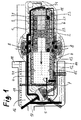
- Fig. 1 and 2 each show in axial section a heat engine according to the invention with reciprocating piston and horizontally arranged cylinder.
- the cylinder 1 has on both sides of the piston 2 displaceable therein back and forth two cylinder chambers 11 and 12, which are filled with a pressurized gas, preferably air.
- piston 2 Trained as a free piston and displaceable in the cylinder 1 piston 2 has a piston skirt 21 with considerable axial extent and has on both sides of large, the volume of the respective cylinder chamber magnifying depressions 22. Between the piston 2 and the cylinder wall 13, a thin sealing gap is formed, which acts like a labyrinth seal, but can slide the piston 2 practically on a gas cushion.
- the piston has rollers 23 in its lower region in order to enable a low-friction piston displacement in the cylinder 1.
- lines 3 and 4 are provided for supplying hot heat transfer medium, in particular hot water in the one or the other cylinder chamber 11, 13 respectively via spray nozzles 31 and 41 in the upper region and preferably in the end wall region of the respective cylinder chamber eleventh , 12 out.
- the cylinder wall 13 is also formed with a thermal insulation 14, which serves to prevent the influx of heat from outside the cylinder.
- the cylinder wall is provided with cooling channels 15, through which a coolant flows, in order to cool the cylinder wall, so that the gas in the cylinder chambers is cooled.
- the coolant is circulated in the embodiment by a coolant pump 6 through the cooling channels 15. The cylinder wall is thereby permanently cooled.
- hot heat transfer medium in particular hot water
- the gas in the cylinder chamber 12 is greatly heated and expands and drives the piston 2 to the left.
- the injected liquid hot heat transfer medium trickles through the cylinder chamber 11 by gravity and collects in the bottom region of the cylinder chamber, where it flows through openings in a collection chamber 6. From the collecting chamber 6, this is discharged as a function of the level of the collected liquid and cooled heat transfer medium through a controlled valve.
- the controlled valve may be a float valve.
- control valve 5 controls the supply of the liquid heat transfer medium in the other, so now the left cylinder chamber 12 to.
- the gas in the right cylinder chamber 11 has already cooled slightly due to the work and is further cooled by the cooled cylinder wall.
- the cylinder wall can be permanently cooled because the strong and rapid heat input caused by the injected hot heat transfer medium direct heat transfer to the gas, which then does work and then cools down again on the cylinder wall.
- electronic sensors 7 may be provided which detect the reaching of the respective end position by the piston 2 and cause the reversal via the control valve 5.
- the output takes place in the embodiment by piezoelectric generators 8, which may be arranged in the center region of the cylinder 1 like a wreath around the entire circumference of the cylinder and, as already mentioned, the European patent EP 2013 965 B1 can correspond to the concept described.
- the stepping piezoelectric packages of these piezoelectric generators 8 interact directly with the piston skirt 21, which moves in the axial direction during the reciprocating movement of the piston relative to the stationary piezoelectric generators 8.
- another conventional electric linear generator can be used to convert the piston movement directly into electrical energy.
- FIG. 2 shows the right part of the FIG. 1 in an enlarged view, to make the details more visible.
- the left part of the Fig. 1 also shows schematically an arrangement for utilizing waste heat for heating the used in the heat engine liquid heat transfer medium, in particular water.
- a chamber 16 is flowed through by an inlet 17 and an outlet 18 of hot exhaust gas from a process, such as combustion, while its heat from water, which is sprayed through spray nozzles 19 as cold water into the chamber 16, this trickles through and thereby Heat from that receives hot process exhaust gas, and finally collects in the lower part of the chamber 16 as hot water, from where it can be removed and fed to the heat engine as a heat transfer medium.
- a compressed gas refill valve 51 is provided, can be refilled by which compressed gas into the corresponding cylinder chamber 11 when the gas pressure in the cylinder chambers 11 and 12 should decrease by gas losses, because in the liquid spent heat transfer medium dissolved gas with the spent heat transfer medium is derived.
- FIG. 3 shows in achssenkrechte cross section an embodiment of the heat engine according to the invention with rotary piston.
- the cylinder 10 and the rotary piston 20 have the known from Wankelmotor ago form.
- the rotary piston is approximately triangular in cross-section with rounded sides and three sealing edges 201, each sliding along the inner wall of the cylinder 10.
- hot heat transfer medium is introduced through an inlet 110 into the cylinder chamber located in each case in the region of this inlet.
- the volume of the relevant cylinder chamber which varies during the circulation in the cylinder, is small and the gas is therefore compressed.
- the gas is heated, expands and drives the rotary piston 20 at.
- the chamber in question continues to circulate, it enters the region of drain holes 120 leading into a spent heat transfer medium collection chamber 130.
- the spent heat transfer medium as described above, depending on the level, for example, be discharged via a designed as a float valve controlled valve.
- the chamber volume increases, as shown by the chamber 103, whereby the gas cools down and accelerates at an accelerated rate. Cooling of the cylinder wall outside the cylinder wall region, in which the injection of the hot heat transfer medium takes place, is advantageous and can be similar to that with respect to the FIGS. 1 and 2 described embodiment carried out.
Landscapes
- Engineering & Computer Science (AREA)
- Chemical & Material Sciences (AREA)
- Combustion & Propulsion (AREA)
- Mechanical Engineering (AREA)
- General Engineering & Computer Science (AREA)
- Engine Equipment That Uses Special Cycles (AREA)
- Processing Of Solid Wastes (AREA)
Priority Applications (5)
| Application Number | Priority Date | Filing Date | Title |
|---|---|---|---|
| JP2016514297A JP2016527425A (ja) | 2013-05-21 | 2014-05-20 | 廃熱と地熱の利用のための方法および熱機関 |
| KR1020157034859A KR20160019429A (ko) | 2013-05-21 | 2014-05-20 | 폐열 또는 지열 열을 이용하기 위한 방법 및 그 열 엔진 |
| PCT/EP2014/001347 WO2014187558A2 (fr) | 2013-05-21 | 2014-05-20 | Procédé et moteur thermique pour exploiter des dégagement de chaleur ou de l'énergie géothermique |
| CN201480041008.0A CN105556067A (zh) | 2013-05-21 | 2014-05-20 | 用于利用废热或地热的方法和热力发动机 |
| US14/948,258 US20160201599A1 (en) | 2013-05-21 | 2015-11-21 | Method and thermal engine for utilizing waste heat or geothermal heat |
Applications Claiming Priority (2)
| Application Number | Priority Date | Filing Date | Title |
|---|---|---|---|
| DE102012018579 | 2012-09-20 | ||
| DE102012024444 | 2012-12-15 |
Publications (2)
| Publication Number | Publication Date |
|---|---|
| EP2711509A2 true EP2711509A2 (fr) | 2014-03-26 |
| EP2711509A3 EP2711509A3 (fr) | 2015-02-25 |
Family
ID=48534115
Family Applications (1)
| Application Number | Title | Priority Date | Filing Date |
|---|---|---|---|
| EP13002654.5A Withdrawn EP2711509A3 (fr) | 2012-09-20 | 2013-05-21 | Procédé et moteur à combustion interne permettant de rendre exploitable les rejets thermiques ou la chaleur géothermique |
Country Status (1)
| Country | Link |
|---|---|
| EP (1) | EP2711509A3 (fr) |
Cited By (4)
| Publication number | Priority date | Publication date | Assignee | Title |
|---|---|---|---|---|
| WO2014187558A3 (fr) * | 2013-05-21 | 2015-03-19 | Richter, Berta | Procédé et moteur thermique pour exploiter des dégagement de chaleur ou de l'énergie géothermique |
| WO2015165581A2 (fr) | 2014-04-27 | 2015-11-05 | Richter, Berta | Procédé et moteur thermique pour exploiter de la chaleur perdue ou de la chaleur géothermique pour produire de l'énergie électrique |
| DE102015009833B3 (de) * | 2015-08-03 | 2017-01-19 | Kocks Technik Gmbh & Co Kg | "Lager für einen Walzenzapfen einer Walze oder für eine Walzenwelle eines Walzgerüsts und Walzgerüst" |
| CN111535891A (zh) * | 2020-06-02 | 2020-08-14 | 西安热工研究院有限公司 | 一种采用直线发电机的梯级回收低温废热发电系统及方法 |
Citations (1)
| Publication number | Priority date | Publication date | Assignee | Title |
|---|---|---|---|---|
| EP2013965B1 (fr) | 2005-12-12 | 2010-09-08 | Richter, Berta | Moteur piézoélectrique utilisé comme système de propulsion de véhicule, servomoteur et analogue |
Family Cites Families (8)
| Publication number | Priority date | Publication date | Assignee | Title |
|---|---|---|---|---|
| US3608311A (en) * | 1970-04-17 | 1971-09-28 | John F Roesel Jr | Engine |
| US3869863A (en) * | 1973-03-22 | 1975-03-11 | Mark A Juge | Rotary steam vapor and external combustion engine |
| US4393653A (en) * | 1980-07-16 | 1983-07-19 | Thermal Systems Limited | Reciprocating external combustion engine |
| WO2010132924A1 (fr) * | 2009-05-18 | 2010-11-25 | Martin De Silva | Système, procédé et composants pour puissance thermique |
| US20110030646A1 (en) * | 2009-08-10 | 2011-02-10 | Barry Leonard D | Jet exhaust piston engine |
| DE102010005232A1 (de) * | 2010-01-21 | 2011-09-08 | Gerhard Stock | Anordnung zum Umwandeln von thermischer in motorische Energie |
| DE102012004158A1 (de) * | 2012-03-05 | 2013-09-05 | Bomat Heiztechnik Gmbh | Anlage zur Nutzung von Wärmeenergie |
| DE202013011700U1 (de) * | 2013-02-07 | 2014-04-08 | En3 Gmbh | Anordnung zur direkten thermopneumatischen oder thermohydraulischen Umwandlung von Dampfenergie in Nutz-Energie |
-
2013
- 2013-05-21 EP EP13002654.5A patent/EP2711509A3/fr not_active Withdrawn
Patent Citations (1)
| Publication number | Priority date | Publication date | Assignee | Title |
|---|---|---|---|---|
| EP2013965B1 (fr) | 2005-12-12 | 2010-09-08 | Richter, Berta | Moteur piézoélectrique utilisé comme système de propulsion de véhicule, servomoteur et analogue |
Cited By (5)
| Publication number | Priority date | Publication date | Assignee | Title |
|---|---|---|---|---|
| WO2014187558A3 (fr) * | 2013-05-21 | 2015-03-19 | Richter, Berta | Procédé et moteur thermique pour exploiter des dégagement de chaleur ou de l'énergie géothermique |
| WO2015165581A2 (fr) | 2014-04-27 | 2015-11-05 | Richter, Berta | Procédé et moteur thermique pour exploiter de la chaleur perdue ou de la chaleur géothermique pour produire de l'énergie électrique |
| WO2015165581A3 (fr) * | 2014-04-27 | 2015-12-23 | Richter, Berta | Procédé et moteur thermique pour exploiter de la chaleur perdue ou de la chaleur géothermique pour produire de l'énergie électrique |
| DE102015009833B3 (de) * | 2015-08-03 | 2017-01-19 | Kocks Technik Gmbh & Co Kg | "Lager für einen Walzenzapfen einer Walze oder für eine Walzenwelle eines Walzgerüsts und Walzgerüst" |
| CN111535891A (zh) * | 2020-06-02 | 2020-08-14 | 西安热工研究院有限公司 | 一种采用直线发电机的梯级回收低温废热发电系统及方法 |
Also Published As
| Publication number | Publication date |
|---|---|
| EP2711509A3 (fr) | 2015-02-25 |
Similar Documents
| Publication | Publication Date | Title |
|---|---|---|
| WO2014187558A2 (fr) | Procédé et moteur thermique pour exploiter des dégagement de chaleur ou de l'énergie géothermique | |
| DE102008042828A1 (de) | Verfahren und Vorrichtung zum Betreiben eines Stirling-Kreisprozesses | |
| EP2711509A2 (fr) | Procédé et moteur à combustion interne permettant de rendre exploitable les rejets thermiques ou la chaleur géothermique | |
| EP2657497B1 (fr) | Convertisseur thermoélectrique avec caloporteur amélioré | |
| DE102018117066A1 (de) | Verfahren zum Betreiben eines Freikolbenlineargenerators | |
| DE19711084A1 (de) | Rotationskolbenmaschine | |
| DE102016122156B4 (de) | Wärmezyklusmaschine | |
| WO2009112145A2 (fr) | Machine à vapeur à piston pour circuit rankine fonctionnant à l'énergie solaire | |
| DE102008004075B4 (de) | Stirlingmotor | |
| DE102010018654B4 (de) | Zyklisch arbeitende Wärme-Kraftmaschine | |
| DE102015101726B4 (de) | Stirlingmaschine sowie Anordnung zur Erzeugung von elektrischer Energie | |
| DE102009017493B4 (de) | Wärmekraftmaschine | |
| CH712956A2 (de) | Doppelwirkende Freikolben-Stirling-Kreislaufmaschine mit Lineargenerator. | |
| DE2518554A1 (de) | Antriebsmaschine mit innerer kontinuierlicher verbrennung | |
| DE3939779A1 (de) | Verfahren und einrichtung zur umwandlung von waermeenergie in mechanische energie | |
| WO2015165581A2 (fr) | Procédé et moteur thermique pour exploiter de la chaleur perdue ou de la chaleur géothermique pour produire de l'énergie électrique | |
| AT520778B1 (de) | Kolbenmaschine | |
| DE10209858B4 (de) | Elektromechanischer Energiewandler | |
| DE19945679C1 (de) | Wärmekraftmaschine | |
| EP4290057B1 (fr) | Dispositif et procédé de conversion de changements d'état quasi-isothermes en force thermique ou processus de machine de travail | |
| DE102014003740A1 (de) | Drehkolbenmotor | |
| DE102012109832B4 (de) | Freikolbenmaschine und Doppelzylinderfreikolbenmaschine | |
| DE202004021028U1 (de) | Wärmekraftmaschine | |
| EP2781702A1 (fr) | Machine de travail thermodynamique | |
| DE19700034A1 (de) | Rotationskolbenmaschine mit exzentrisch zum Zylinder angeordnetem Drehkolben |
Legal Events
| Date | Code | Title | Description |
|---|---|---|---|
| PUAI | Public reference made under article 153(3) epc to a published international application that has entered the european phase |
Free format text: ORIGINAL CODE: 0009012 |
|
| AK | Designated contracting states |
Kind code of ref document: A2 Designated state(s): AL AT BE BG CH CY CZ DE DK EE ES FI FR GB GR HR HU IE IS IT LI LT LU LV MC MK MT NL NO PL PT RO RS SE SI SK SM TR |
|
| AX | Request for extension of the european patent |
Extension state: BA ME |
|
| PUAL | Search report despatched |
Free format text: ORIGINAL CODE: 0009013 |
|
| AK | Designated contracting states |
Kind code of ref document: A3 Designated state(s): AL AT BE BG CH CY CZ DE DK EE ES FI FR GB GR HR HU IE IS IT LI LT LU LV MC MK MT NL NO PL PT RO RS SE SI SK SM TR |
|
| AX | Request for extension of the european patent |
Extension state: BA ME |
|
| RIC1 | Information provided on ipc code assigned before grant |
Ipc: F01K 21/02 20060101ALI20150120BHEP Ipc: F01K 7/36 20060101ALI20150120BHEP Ipc: F01K 27/00 20060101ALI20150120BHEP Ipc: F01K 11/00 20060101AFI20150120BHEP |
|
| 17P | Request for examination filed |
Effective date: 20150806 |
|
| RBV | Designated contracting states (corrected) |
Designated state(s): AL AT BE BG CH CY CZ DE DK EE ES FI FR GB GR HR HU IE IS IT LI LT LU LV MC MK MT NL NO PL PT RO RS SE SI SK SM TR |
|
| STAA | Information on the status of an ep patent application or granted ep patent |
Free format text: STATUS: THE APPLICATION IS DEEMED TO BE WITHDRAWN |
|
| 18D | Application deemed to be withdrawn |
Effective date: 20171201 |