EP2711574A1 - Kugellager und Verfahren zur Herstellung eines Kugellagers - Google Patents
Kugellager und Verfahren zur Herstellung eines Kugellagers Download PDFInfo
- Publication number
- EP2711574A1 EP2711574A1 EP12184958.2A EP12184958A EP2711574A1 EP 2711574 A1 EP2711574 A1 EP 2711574A1 EP 12184958 A EP12184958 A EP 12184958A EP 2711574 A1 EP2711574 A1 EP 2711574A1
- Authority
- EP
- European Patent Office
- Prior art keywords
- ring
- outer part
- ball bearing
- encapsulation
- rings
- Prior art date
- Legal status (The legal status is an assumption and is not a legal conclusion. Google has not performed a legal analysis and makes no representation as to the accuracy of the status listed.)
- Granted
Links
- 238000004519 manufacturing process Methods 0.000 title claims abstract description 9
- 238000000034 method Methods 0.000 title claims abstract description 8
- 238000005538 encapsulation Methods 0.000 claims description 17
- 238000002347 injection Methods 0.000 claims description 8
- 239000007924 injection Substances 0.000 claims description 8
- 230000001747 exhibiting effect Effects 0.000 claims description 4
- 238000001125 extrusion Methods 0.000 claims 1
- 238000011161 development Methods 0.000 description 4
- 230000018109 developmental process Effects 0.000 description 4
- 239000000919 ceramic Substances 0.000 description 2
- 238000005096 rolling process Methods 0.000 description 2
- 239000002253 acid Substances 0.000 description 1
- 150000007513 acids Chemical class 0.000 description 1
- 230000015572 biosynthetic process Effects 0.000 description 1
- 238000010586 diagram Methods 0.000 description 1
- 238000004049 embossing Methods 0.000 description 1
- 238000007765 extrusion coating Methods 0.000 description 1
- 239000011521 glass Substances 0.000 description 1
- 238000009434 installation Methods 0.000 description 1
- 230000002093 peripheral effect Effects 0.000 description 1
- 238000002360 preparation method Methods 0.000 description 1
- 238000003860 storage Methods 0.000 description 1
- 239000000126 substance Substances 0.000 description 1
Images

Classifications
-
- F—MECHANICAL ENGINEERING; LIGHTING; HEATING; WEAPONS; BLASTING
- F16—ENGINEERING ELEMENTS AND UNITS; GENERAL MEASURES FOR PRODUCING AND MAINTAINING EFFECTIVE FUNCTIONING OF MACHINES OR INSTALLATIONS; THERMAL INSULATION IN GENERAL
- F16C—SHAFTS; FLEXIBLE SHAFTS; ELEMENTS OR CRANKSHAFT MECHANISMS; ROTARY BODIES OTHER THAN GEARING ELEMENTS; BEARINGS
- F16C33/00—Parts of bearings; Special methods for making bearings or parts thereof
- F16C33/30—Parts of ball or roller bearings
- F16C33/58—Raceways; Race rings
- F16C33/60—Raceways; Race rings divided or split, e.g. comprising two juxtaposed rings
-
- F—MECHANICAL ENGINEERING; LIGHTING; HEATING; WEAPONS; BLASTING
- F16—ENGINEERING ELEMENTS AND UNITS; GENERAL MEASURES FOR PRODUCING AND MAINTAINING EFFECTIVE FUNCTIONING OF MACHINES OR INSTALLATIONS; THERMAL INSULATION IN GENERAL
- F16C—SHAFTS; FLEXIBLE SHAFTS; ELEMENTS OR CRANKSHAFT MECHANISMS; ROTARY BODIES OTHER THAN GEARING ELEMENTS; BEARINGS
- F16C19/00—Bearings with rolling contact, for exclusively rotary movement
- F16C19/02—Bearings with rolling contact, for exclusively rotary movement with bearing balls essentially of the same size in one or more circular rows
- F16C19/04—Bearings with rolling contact, for exclusively rotary movement with bearing balls essentially of the same size in one or more circular rows for radial load mainly
- F16C19/06—Bearings with rolling contact, for exclusively rotary movement with bearing balls essentially of the same size in one or more circular rows for radial load mainly with a single row or balls
-
- F—MECHANICAL ENGINEERING; LIGHTING; HEATING; WEAPONS; BLASTING
- F16—ENGINEERING ELEMENTS AND UNITS; GENERAL MEASURES FOR PRODUCING AND MAINTAINING EFFECTIVE FUNCTIONING OF MACHINES OR INSTALLATIONS; THERMAL INSULATION IN GENERAL
- F16C—SHAFTS; FLEXIBLE SHAFTS; ELEMENTS OR CRANKSHAFT MECHANISMS; ROTARY BODIES OTHER THAN GEARING ELEMENTS; BEARINGS
- F16C33/00—Parts of bearings; Special methods for making bearings or parts thereof
- F16C33/30—Parts of ball or roller bearings
- F16C33/58—Raceways; Race rings
- F16C33/64—Special methods of manufacture
-
- F—MECHANICAL ENGINEERING; LIGHTING; HEATING; WEAPONS; BLASTING
- F16—ENGINEERING ELEMENTS AND UNITS; GENERAL MEASURES FOR PRODUCING AND MAINTAINING EFFECTIVE FUNCTIONING OF MACHINES OR INSTALLATIONS; THERMAL INSULATION IN GENERAL
- F16C—SHAFTS; FLEXIBLE SHAFTS; ELEMENTS OR CRANKSHAFT MECHANISMS; ROTARY BODIES OTHER THAN GEARING ELEMENTS; BEARINGS
- F16C43/00—Assembling bearings
- F16C43/04—Assembling rolling-contact bearings
-
- F—MECHANICAL ENGINEERING; LIGHTING; HEATING; WEAPONS; BLASTING
- F16—ENGINEERING ELEMENTS AND UNITS; GENERAL MEASURES FOR PRODUCING AND MAINTAINING EFFECTIVE FUNCTIONING OF MACHINES OR INSTALLATIONS; THERMAL INSULATION IN GENERAL
- F16C—SHAFTS; FLEXIBLE SHAFTS; ELEMENTS OR CRANKSHAFT MECHANISMS; ROTARY BODIES OTHER THAN GEARING ELEMENTS; BEARINGS
- F16C2220/00—Shaping
- F16C2220/02—Shaping by casting
- F16C2220/04—Shaping by casting by injection-moulding
Definitions
- the invention relates to a ball bearing according to the preamble of claim 1.
- the invention further relates to a method for producing a ball bearing according to claim 6.
- Ball bearings are known in different versions. They consist essentially of an inner ring and a coaxially arranged to this outer ring, which each have opposite one another in each case a guide in the form of a raceway. Between the grooves grooves are introduced as rolling elements, which are regularly held by a cage at the same distance. Ball bearings are also made of plastic in particular, with rolling elements made of glass or ceramic are used, which are, inter alia, resistant to aggressive acids or alkalis in the chemical and food industries. The installation of such ball bearings proves to be very expensive. In particular, the introduction of the fitted with balls ball cage between inner ring and outer ring designed problematic, since the balls should be arranged as possible clearance between the grooves of inner and outer ring.
- the invention aims to remedy this situation.
- the invention is based on the object to provide a ball bearing, which allows a simple and fully automated assembly. According to the invention, this object is solved by the features of the characterizing part of patent claim 1.
- a ball bearing is provided that allows a simple and automated assembly.
- the formation of the outer ring by two outer part rings, the introduction of the balls is simplified.
- the two outer part rings are connected to each other by a circumferential encapsulation.
- At least two notches are introduced into at least one outer part ring on its outer side ring facing away from the outer part ring, engage in the tabs arranged on the encapsulation radially inwardly cantilevered.
- Such notches are preferably introduced into both outer part rings, into which tabs arranged cantilevered radially inwardly on the encapsulation.
- the two outer part rings are formed identically. As a result, the production of the outer part rings is simplified. In addition, the posture is minimized.
- the invention is further based on the object to provide a method for producing a ball bearing, in which the assembly is simplified and automated feasible. According to the invention, this object is solved by the features of patent claim 6.
- a method for producing a ball bearing is provided that is easy and automated to assemble. Characterized in that first a first half raceway exhibiting outer part ring and subsequently an inner ring provided with a ball cage is inserted into the Umspritzungskavmaschine the tool, the positioning of the ball cage, which only has to be pushed onto the inner ring, designed as unproblematic. Subsequently, a second half raceway exhibiting outer part ring is inserted to the first outer race, whereby a common running groove exhibiting Outer ring is formed, against which the ball cage. Subsequently, the two outer part rings in the Umspritzungskavmaschineradially encircling, after which the finished ball bearing can be discharged from the tool.
- At least one outer part ring in at least one outer part ring, preferably at both outer part rings on its outer outer ring facing away from each outer outer ring at least two, preferably three offset by 120 ° to each other arranged notches introduced, which are filled in the Umspritzvorgang.
- the two outer part rings are so connected to an outer ring with inner raceway.
- two identically formed outer rings are used.
- the storage is minimized.
- the ball bearing 1 chosen as an exemplary embodiment is formed from a raceway 21 having an inner ring 2 and a coaxially arranged therewith, a raceway 31 having outer ring 3. Between the raceway 21 of the inner ring 2 and the raceway groove 31 of the outer ring 3 is a stocked with balls 41 Ball cage 4 arranged. The balls 41 rest against the raceway grooves 21, 31 of the inner ring 2 and outer ring 3, respectively.
- the outer ring 3 is formed from two identical outer part rings 32, on the mutually facing inner sides of a radius 33 is formed, which forms a half groove 31.
- the two outer part rings 32 have, on their outer side facing away from the respective outer part ring 32, an outer diameter-reduced shoulder 34, which is provided with notches 120 each offset by 120 ° from one another.
- the two outer part rings 32 are connected to each other via an encapsulation 5.
- the encapsulation 5 is - like FIG. 5 to be taken - formed in the form of a hollow cylinder, which on both sides with an inwardly cantilevered circumferential Edge 51 is provided. Furthermore, three each offset by 120 ° to each other radially inwardly cantilevered tabs are integrally formed on the extrusion coating 5.
- the inner wall of the encapsulation 5 abuts the outer part rings 32 on the outside, wherein the peripheral edge 51 arranged on both sides of the encapsulation 5 bears against the diameter-reduced shoulder 34 of the outer part rings 32.
- the tabs 52 of the encapsulation 5 engage in the notches 35 of the outer part rings 32 a. Through the encapsulation 5, the two outer part rings 32 are connected to form an outer ring 3.
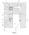
- an outer part ring 32 is inserted into the Umspritzkavtician 63 of the ejector side first mold half 61 of an injection mold 6. Subsequently, the inner ring 2, onto which a ball cage 41 provided with balls 41 has been pushed, is inserted into the ejector-side first tool half 61.
- the ball cage 4 comprises in the exemplary embodiment twelve ceramic balls.
- a second outer part ring 32 is inserted into the nozzle-side, second mold half 62 of the injection mold 6. In the lower half of the illustration in FIG. 6 the injection mold 6 is shown in the open position. After closing the injection mold 6, the two outer part rings 32 abut each other.
- FIG. 6 shows the injection mold 6 in the closed position during the encapsulation process.
- three Anspritzpumpe for encapsulating the outer part rings 32 are arranged.
- the injection mold 6 is opened and the finished ball bearing 1 is removed from the mold via the ejector 64.
Landscapes
- Engineering & Computer Science (AREA)
- General Engineering & Computer Science (AREA)
- Mechanical Engineering (AREA)
- Manufacturing & Machinery (AREA)
- Rolling Contact Bearings (AREA)
Abstract
Description
- Die Erfindung betrifft ein Kugellager nach dem Oberbegriff des Patentanspruchs 1. Die Erfindung betrifft weiterhin ein Verfahren zur Herstellung eines Kugellagers nach dem Patentanspruch 6.
- Kugellager sind in unterschiedlichen Ausführungen bekannt. Sie bestehen im Wesentlichen aus einem Innenring sowie einem koaxial zu diesem angeordneten Außenring, die zueinander gegenüberliegend jeweils eine Führung in Form einer Laufrille aufweisen. Zwischen den Laufrillen sind Kugeln als Wälzkörper eingebracht, die regelmäßig durch einen Käfig in gleichem Abstand gehalten werden. Kugellager werden insbesondere auch aus Kunststoff hergestellt, wobei Wälzkörper aus Glas oder Keramik zum Einsatz kommen, welche unter anderem beständig gegen aggressive Säuren oder Laugen in der Chemie- und Lebensmittelindustrie sind. Die Montage solcher Kugellager erweist sich nach wie vor als sehr aufwendig. Dabei gestaltet sich insbesondere das Einbringen des mit Kugeln bestücktem Kugelkäfigs zwischen Innenring und Außenring problematisch, da die Kugeln möglichst Spielfrei zwischen den Laufrillen von Innen- und Außenring angeordnet sein sollen.
- Hier will die Erfindung Abhilfe schaffen. Der Erfindung liegt die Aufgabe zu Grunde ein Kugellager bereitzustellen, das eine einfache und vollautomatisierte Montage ermöglicht. Gemäß der Erfindung wird diese Aufgabe durch die Merkmale des kennzeichnenden Teils des Patentanspruchs 1 gelöst.
- Mit der Erfindung ist ein Kugellager geschaffen, dass eine einfache und automatisierte Montage ermöglicht. Durch die Ausbildung des Außenrings durch zwei Außenteilringe ist das Einbringen der Kugeln vereinfacht. Die beiden Außenteilringe sind durch eine radial umlaufende Umspritzung miteinander verbunden.
- In Weiterbildung der Erfindung weist wenigstens ein Außenteilring an seiner dem gegenüberliegenden Außenteilring abgewandten Außenseite einen außendurchmesserverminderten Absatz auf, in den die Umspritzung eingreift. Hierdurch ist eine gute Fixierung der beiden Außenteilringe erzielt.
- In weiterer Ausgestaltung der Erfindung sind in wenigstens einem Außenteilring an seiner dem gegenüberliegenden Außenteilring abgewandten Außenseite wenigstens zwei Kerben eingebracht, in die an der Umspritzung radial nach innen kragend angeordnete Laschen eingreifen. Hierdurch ist eine zuverlässige axiale Fixierung der beiden Außenteilringe bewirkt. Bevorzugt sind in beiden Außenteilringen solche Kerben eingebracht, in die an der Umspritzung radial nach innen kragend angeordnete Laschen eingreifen. Bevorzugt sind drei jeweils um 120° zueinander versetzt angeordnete Kerben angeordnet, in die an der Umspritzung radial nach innen kragend angeordnete Laschen eingreifen.
- In Weiterbildung der Erfindung sind die beiden Außenteilringe identisch ausgebildet. Hierdurch ist die Herstellung der Außenteilringe vereinfacht. Zudem ist die Lagehaltung minimiert.
- Der Erfindung liegt weiterhin die Aufgabe zu Grunde, ein Verfahren zur Herstellung eines Kugellagers bereitzustellen, bei dem die Montage vereinfacht und automatisiert durchführbar ist. Gemäß der Erfindung wird diese Aufgabe durch die Merkmale des Patentanspruchs 6 gelöst.
- Mit der Erfindung ist ein Verfahren zur Herstellung eines Kugellagers geschaffen, dass einfach und automatisiert montierbar ist. Dadurch, dass zunächst ein erster eine halbe Laufrille aufweisender Außenteilring und nachfolgend ein mit einem Kugelkäfig versehener Innenring in die Umspritzungskavität des Werkzeugs eingelegt wird, gestaltet sich die Positionierung des Kugelkäfigs, der lediglich auf den Innenring aufgeschoben werden muss, als unproblematisch. Anschließend wird ein zweiter eine halbe Laufrille aufweisender Außenteilring an den ersten Außenteilring eingelegt, wodurch ein eine gemeinsame Laufrille aufweisender Außenring gebildet ist, an dem der Kugelkäfig anliegt. Anschließend werden die beiden Außenteilringe in der Umspritzungskavität radial umlaufend umspritzt, wonach das fertige Kugellager aus dem Werkzeug ausgebracht werden kann.
- In Weiterbildung der Erfindung weist wenigstens ein Außenteilring an seiner dem gegenüberliegenden Außenteilring abgewandten Außenseite einen außendurchmesserverminderten Absatz auf, der bei dem Umspritzvorgang aufgefüllt wird. Hierdurch ist eine gute Fixierung der beiden Außenteilringe bewirkt.
- In weiterer Ausgestaltung der Erfindung sind in wenigstens einem Außenteilring, bevorzugt an beiden Außenteilringen an ihrer dem jeweils gegenüberliegenden Außenteilring abgewandten Außenseite wenigstens zwei, bevorzugt drei jeweils um 120° zueinander versetzt angeordnete Kerben eingebracht, die bei dem Umspritzvorgang aufgefüllt werden. Hierdurch ist eine gute axiale Fixierung der beiden Außenteilringe bewirkt. Die beiden Außenteilringe sind so zu einem Außenring mit innen liegender Laufrille verbunden.
- Bevorzugt werden zwei identisch ausgebildete Außenringe eingesetzt. Hierdurch ist die Lagerhaltung minimiert.
- Andere Weiterbildungen und Ausgestaltungen der Erfindung sind in den übrigen Unteransprüchen angegeben. Ein Ausführungsbeispiel der Erfindung ist in den Zeichnungen dargestellt und wird nachfolgend im Einzelnen beschrieben. Es zeigen:
-
Figur 1 die schematische Darstellung eines Kugellagers; -
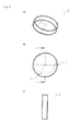
Figur 2 den Innenring des Kugellagers ausFigur 1 - a) in räumlicher Darstellung;
- b) in Draufsicht;
- c) in Seitenansicht;
-
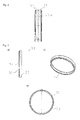
Figur 3 die schematische Darstellung des aus zwei Außenteilringen gebildeten Außenrings des Kugellagers ausFigur 1 ohne Umspritzung; -
Fig. 4 die Darstellung eines Außenteilrings des Außenrings ausFigur 3 - a) in Draufsicht;
- b) in räumlicher Darstellung;
- c) in Seitenansicht;
-
Fig. 5 die schematische Darstellung der Umspritzung des Außenrings des Kugellagers ausFigur 1 - a) in räumlicher Darstellung
- b) in Seitenansicht
- c) in Draufsicht
-
Fig. 6 die schematische Darstellung eines Verfahrens zur Herstellung eines Verfahrens zur Herstellung eines Kugellagers. - Das als Ausführungsbeispiel gewählte Kugellager 1 ist gebildet aus einem eine Laufrille 21 aufweisenden Innenring 2 sowie einem koaxial zu diesem angeordneten, eine Laufrille 31 aufweisenden Außenring 3. Zwischen der Laufrille 21 des Innenrings 2 und der Laufrille 31 des Außenrings 3 ist ein mit Kugeln 41 bestückter Kugelkäfig 4 angeordnet. Die Kugeln 41 liegen dabei an den Laufrillen 21, 31 von Innenring 2 bzw. Außenring 3 an.
- Der Außenring 3 ist gebildet aus zwei identischen Außenteilringen 32, an deren zueinander zugewandten Innenseiten ein Radius 33 eingeformt ist, der eine halbe Laufrille 31 ausbildet. Die beiden Außenteilringe 32 weisen an ihrer dem jeweils gegenüberliegenden Außenteilring 32 abgewandten Außenseite einen außendurchmesserverminderten Absatz 34 auf, der mit jeweils um 120° zueinander versetzt angeordneten Kerben 35 versehen ist.
- Die beiden Außenteilringe 32 sind über eine Umspritzung 5 miteinander verbunden. Die Umspritzung 5 ist - wie
Figur 5 zu entnehmen - in Form eines Hohlzylinders ausgebildet, der an beiden Seiten mit einem nach innen kragenden umlaufenden Rand 51 versehen ist. Weiterhin sind an der Umspritzung 5 drei jeweils um 120° zueinander versetzt radial nach innen kragend angeordnete Laschen angeformt. Die Innenwand der Umspritzung 5 liegt außen an den Außenteilringen 32 an, wobei der an beiden Seiten der Umspritzung 5 angeordnete umlaufende Rand 51 an dem durchmesserreduzierten Absatz 34 der Außenteilringe 32 anliegt. Die Laschen 52 der Umspritzung 5 greifen dabei in die Kerben 35 der Außenteilringe 32 ein. Durch die Umspritzung 5 sind die beiden Außenteilringe 32 so zu einem Außenring 3 verbunden. - Die Herstellung des zuvor beschriebenen Kugellagers wird nachfolgend anhand der Prinzipskizze gemäß
Figur 6 erläutert. Zunächst wird ein Außenteilring 32 in die Umspritzkavität 63 der auswerferseitigen ersten Werkzeughälfte 61 eines Spritzgießwerkzeugs 6 eingesetzt. Nachfolgend wird der Innenring 2, auf den ein mit Kugeln 41 versehener Kugelkäfig 4 aufgeschoben wurde, in die auswerferseitige erste Werkzeughälfte 61 eingelegt. Der Kugelkäfig 4 umfasst im Ausführungsbeispiel zwölf Keramikkugeln. Anschließend wird ein zweiter Außenteilring 32 in die düsenseitige, zweite Werkzeughälfte 62 des Spritzgießwerkzeugs 6 eingelegt. In der unteren Hälfte der Darstellung inFigur 6 ist das Spritzgießwerkzeug 6 in geöffneter Position gezeigt. Nach Schließen des Spritzgießwerkzeugs 6 liegen die beiden Außenteilringe 32 aneinander an. Über die Düse 65 des Spritzgießwerkzeugs 6 werden nun die beiden aneinander liegenden Außenteilringe 32 umspritzt, wobei der Durchmesser verminderte Absatz 34 sowie die Kerben 35 der Außenteilringe 32 verfüllt werden. Die obere Hälfte derFigur 6 zeigt das Spritzgießwerkzeug 6 in geschlossener Position beim Umspritzvorgang. Im Ausführungsbeispiel sind drei Anspritzpumpe zum Umspritzen der Außenteilringe 32 angeordnet. Nachfolgend wird das Spritzgießwerkzeug 6 geöffnet und das fertige Kugellager 1 wird über den Auswerfer 64 entformt.
Claims (9)
- Kugellager (1), umfassend einen Innenring (2) und einen koaxial zu diesem angeordneten Außenring (3), die zueinander gegenüberliegend jeweils eine Laufrille (21, 31) aufweisen, wobei zwischen den Laufrillen (21, 31) von diesen eingefasst Kugeln (41) eingebracht sind, dadurch gekennzeichnet, dass der Außenring (3) durch zwei Außenteilringe (32) gebildet ist, die durch eine radial umlaufende Umspritzung (5) miteinander verbunden sind.
- Kugellager nach Anspruch 1, dadurch gekennzeichnet, dass wenigstens ein Außenteilring (32) an seiner dem gegenüberliegenden Außenteilring (32) abgewandten Außenseite einen außendurchmesserverminderten Absatz (34) aufweist, in den die Umspritzung (5) eingreift.
- Kugellager nach Anspruch 1 oder 2, dadurch gekennzeichnet, dass in wenigstens einem Außenteilring (32) an seiner dem gegenüberliegenden Außenteilring (32) abgewandten Außenseite wenigstens zwei Kerben (35) eingebracht sind, in die an der Umspritzung (5) radial nach innen kragend angeordnete Laschen (52) eingreifen.
- Kugellager nach Anspruch 3, dadurch gekennzeichnet, dass drei jeweils um 120° zueinander versetzt angeordnete Kerben (35) angeordnet sind, in die an der Umspritzung (5) radial nach innen kragend angeordnete Laschen (52) eingreifen.
- Kugellager nach einem der vorgenannten Ansprüche, dadurch gekennzeichnet, dass die beiden Außenteilringe (32) identisch ausgebildet sind.
- Verfahren zur Herstellung eines Kugellagers (1) nach einem der Vorgenannten Ansprüche, wobei zunächst in ein Spritzgießwerkzeug (6), das eine Umspritzungskavität (63) für ein komplettes Kugellager (1) aufweist, ein erster eine halbe Laufrille aufweisender Außenteilring (32) und nachfolgend ein mit einem mit Kugeln (41) bestückten Kugelkäfig (4) versehener Innenring (2) eingelegt wird, anschließend ein zweiter eine halbe Laufrille aufweisender Außenteilring (32) derart an den ersten Außenteilring (32) eingelegt wird, dass eine gemeinsame Laufrille (31) gebildet ist, an welcher die Kugeln (41) des Kugelkäfigs (4) anliegen und nachfolgend die beiden Außenteilringe (32) radial umlaufend umspritzt werden.
- Verfahren nach Anspruch 6, dadurch gekennzeichnet, dass wenigstens ein Außenteilring (32) an seiner dem gegenüberliegenden Außenteilring (32) abgewandten Außenseite einen außendurchmesserverminderten Absatz (34) aufweist, der bei dem Umspritzvorgang aufgefüllt wird.
- Verfahren nach Anspruch 6 oder 7, dadurch gekennzeichnet, dass in wenigstens einem Außenteilring (32) an seiner dem gegenüberliegenden Außenteilring (32) abgewandten Außenseite wenigstens zwei Kerben (35) eingebracht sind, die bei dem Umspritzvorgang aufgefüllt werden.
- Verfahren nach einem der Ansprüche 6 bis 8, dadurch gekennzeichnet, dass zwei identisch ausgebildete Außenteilringe (32) eingesetzt werden.
Priority Applications (1)
| Application Number | Priority Date | Filing Date | Title |
|---|---|---|---|
| EP12184958.2A EP2711574B8 (de) | 2012-09-19 | 2012-09-19 | Kugellager und Verfahren zur Herstellung eines Kugellagers |
Applications Claiming Priority (1)
| Application Number | Priority Date | Filing Date | Title |
|---|---|---|---|
| EP12184958.2A EP2711574B8 (de) | 2012-09-19 | 2012-09-19 | Kugellager und Verfahren zur Herstellung eines Kugellagers |
Publications (3)
| Publication Number | Publication Date |
|---|---|
| EP2711574A1 true EP2711574A1 (de) | 2014-03-26 |
| EP2711574B1 EP2711574B1 (de) | 2017-04-05 |
| EP2711574B8 EP2711574B8 (de) | 2017-07-19 |
Family
ID=46980780
Family Applications (1)
| Application Number | Title | Priority Date | Filing Date |
|---|---|---|---|
| EP12184958.2A Active EP2711574B8 (de) | 2012-09-19 | 2012-09-19 | Kugellager und Verfahren zur Herstellung eines Kugellagers |
Country Status (1)
| Country | Link |
|---|---|
| EP (1) | EP2711574B8 (de) |
Citations (7)
| Publication number | Priority date | Publication date | Assignee | Title |
|---|---|---|---|---|
| DE1980171U (de) * | 1967-11-25 | 1968-02-29 | Markes & Co K G | Laufrolle fuer roellchenbahn. |
| DE2529913A1 (de) * | 1975-07-04 | 1977-01-20 | Skf Kugellagerfabriken Gmbh | Verfahren zum herstellen von laufrollen o.dgl. durch umspritzen von mindestens einem waelzlager mit kunststoff und nach diesem verfahren hergestellte laufrolle o.dgl. |
| DE8020620U1 (de) * | 1980-11-06 | Brueckl, Franz, 8100 Garmisch-Partenkirchen | Rollschuhrolle | |
| DE19918889A1 (de) * | 1999-03-26 | 2000-09-28 | Ghs Plastic Gmbh Ruhla | Reibrolle, insbesondeere Ketten- oder Stufenrolle für Fahrtreppen |
| DE102006025307A1 (de) * | 2006-05-31 | 2007-12-06 | Vorwerk & Co. Interholding Gmbh | Verfahren zur Festlegung von Kugellagern sowie Einbauteil beispielsweise einer Küchenmaschine mit einer Welle |
| DE102008007168A1 (de) * | 2008-02-01 | 2009-08-06 | Ab Skf | Gelenkwellen-Zwischenlagerung |
| WO2010072269A1 (en) * | 2008-12-23 | 2010-07-01 | Aktiebolaget Skf | A bearing unit and manufacturing methods thereof |
-
2012
- 2012-09-19 EP EP12184958.2A patent/EP2711574B8/de active Active
Patent Citations (7)
| Publication number | Priority date | Publication date | Assignee | Title |
|---|---|---|---|---|
| DE8020620U1 (de) * | 1980-11-06 | Brueckl, Franz, 8100 Garmisch-Partenkirchen | Rollschuhrolle | |
| DE1980171U (de) * | 1967-11-25 | 1968-02-29 | Markes & Co K G | Laufrolle fuer roellchenbahn. |
| DE2529913A1 (de) * | 1975-07-04 | 1977-01-20 | Skf Kugellagerfabriken Gmbh | Verfahren zum herstellen von laufrollen o.dgl. durch umspritzen von mindestens einem waelzlager mit kunststoff und nach diesem verfahren hergestellte laufrolle o.dgl. |
| DE19918889A1 (de) * | 1999-03-26 | 2000-09-28 | Ghs Plastic Gmbh Ruhla | Reibrolle, insbesondeere Ketten- oder Stufenrolle für Fahrtreppen |
| DE102006025307A1 (de) * | 2006-05-31 | 2007-12-06 | Vorwerk & Co. Interholding Gmbh | Verfahren zur Festlegung von Kugellagern sowie Einbauteil beispielsweise einer Küchenmaschine mit einer Welle |
| DE102008007168A1 (de) * | 2008-02-01 | 2009-08-06 | Ab Skf | Gelenkwellen-Zwischenlagerung |
| WO2010072269A1 (en) * | 2008-12-23 | 2010-07-01 | Aktiebolaget Skf | A bearing unit and manufacturing methods thereof |
Also Published As
| Publication number | Publication date |
|---|---|
| EP2711574B8 (de) | 2017-07-19 |
| EP2711574B1 (de) | 2017-04-05 |
Similar Documents
| Publication | Publication Date | Title |
|---|---|---|
| DE2554137A1 (de) | Wellendichtung, und verfahren zu ihrer herstellung | |
| DE2810615A1 (de) | Kunststoffschraubenaugenring | |
| DE102011005407B4 (de) | Konzept für einen geschlitzten Lagerkäfig | |
| EP2158412B1 (de) | Lageranordnung | |
| WO2016023848A1 (de) | Spurverbreiterungssystem für kraftfahrzeuge | |
| EP2796726A1 (de) | Statorelement für eine Holweckpumpstufe, Vakuumpumpe mit einer Holweckpumpstufe und Verfahren zur Herstellung eines Statorelements für eine Holweckpumpstufe | |
| DE102014213634A1 (de) | Kammkäfig aus Kunststoff und Verfahren zu seiner Herstellung | |
| DE102018127561A1 (de) | Wälzlagerkäfig und Verfahren zur Herstellung eines Kugellagers | |
| EP2711574B1 (de) | Kugellager und Verfahren zur Herstellung eines Kugellagers | |
| DE102015200376A1 (de) | Rillenkugellager mit einem radial geteilten Außenring | |
| DE102012222835A1 (de) | Kugelgewindetrieb mit außenmontiertem Umlenkkörper | |
| DE102013111837B4 (de) | Verfahren zur Herstellung einer Nockenwelle in Leichtbauweise | |
| DE102015207872A1 (de) | Käfig für ein zweireihiges Nadellager | |
| DE102017116356A1 (de) | Rollenwälzlager | |
| DE10220419A1 (de) | Zylinderrollenlager | |
| DE102012200674A1 (de) | Zwei- oder mehrreihiges Schrägkugellager | |
| DE102010019943B4 (de) | Verfahren zum Herstellen eines Wälzlagerkäfigs und Wälzlagerkäfig | |
| WO2016008539A1 (de) | Verschlusselement | |
| DE102015223971A1 (de) | Kegelrollenlager | |
| DE102014213411A1 (de) | Ausrücklager mit einem Kugelgewindetrieb | |
| DE102016222439A1 (de) | Wälzlager mit einem Wälzlagerkäfig | |
| DE102009039719A1 (de) | Käfig für ein Lager | |
| DE102007050498B4 (de) | Verfahren zur Herstellung von Schlitzen in der Bodenwand einer napfförmigen Hülsenanordnung | |
| DE102010006803A1 (de) | Kegelrollenlager und Verfahren zur Montage eines Kegelrollenlagers | |
| DE102012224230A1 (de) | Verfahren zur Herstellung eines Kühlkanalkolbens für eine Brennkraftmaschine sowie ein nach diesem Verfahren hergestellter Kühlkanalkolben |
Legal Events
| Date | Code | Title | Description |
|---|---|---|---|
| PUAI | Public reference made under article 153(3) epc to a published international application that has entered the european phase |
Free format text: ORIGINAL CODE: 0009012 |
|
| AK | Designated contracting states |
Kind code of ref document: A1 Designated state(s): AL AT BE BG CH CY CZ DE DK EE ES FI FR GB GR HR HU IE IS IT LI LT LU LV MC MK MT NL NO PL PT RO RS SE SI SK SM TR |
|
| AX | Request for extension of the european patent |
Extension state: BA ME |
|
| 17P | Request for examination filed |
Effective date: 20140714 |
|
| RAX | Requested extension states of the european patent have changed |
Extension state: BA Payment date: 20140714 Extension state: ME Payment date: 20140714 |
|
| RBV | Designated contracting states (corrected) |
Designated state(s): AL AT BE BG CH CY CZ DE DK EE ES FI FR GB GR HR HU IE IS IT LI LT LU LV MC MK MT NL NO PL PT RO RS SE SI SK SM TR |
|
| RAP1 | Party data changed (applicant data changed or rights of an application transferred) |
Owner name: NP GERMANY GMBH |
|
| GRAP | Despatch of communication of intention to grant a patent |
Free format text: ORIGINAL CODE: EPIDOSNIGR1 |
|
| RIC1 | Information provided on ipc code assigned before grant |
Ipc: F16C 33/64 20060101ALI20160909BHEP Ipc: F16C 43/04 20060101AFI20160909BHEP Ipc: F16C 33/60 20060101ALI20160909BHEP Ipc: F16C 19/06 20060101ALI20160909BHEP |
|
| INTG | Intention to grant announced |
Effective date: 20161012 |
|
| GRAS | Grant fee paid |
Free format text: ORIGINAL CODE: EPIDOSNIGR3 |
|
| GRAJ | Information related to disapproval of communication of intention to grant by the applicant or resumption of examination proceedings by the epo deleted |
Free format text: ORIGINAL CODE: EPIDOSDIGR1 |
|
| GRAL | Information related to payment of fee for publishing/printing deleted |
Free format text: ORIGINAL CODE: EPIDOSDIGR3 |
|
| INTC | Intention to grant announced (deleted) | ||
| GRAR | Information related to intention to grant a patent recorded |
Free format text: ORIGINAL CODE: EPIDOSNIGR71 |
|
| GRAA | (expected) grant |
Free format text: ORIGINAL CODE: 0009210 |
|
| INTG | Intention to grant announced |
Effective date: 20170127 |
|
| AK | Designated contracting states |
Kind code of ref document: B1 Designated state(s): AL AT BE BG CH CY CZ DE DK EE ES FI FR GB GR HR HU IE IS IT LI LT LU LV MC MK MT NL NO PL PT RO RS SE SI SK SM TR |
|
| AX | Request for extension of the european patent |
Extension state: BA ME |
|
| REG | Reference to a national code |
Ref country code: GB Ref legal event code: FG4D Free format text: NOT ENGLISH |
|
| REG | Reference to a national code |
Ref country code: CH Ref legal event code: EP |
|
| REG | Reference to a national code |
Ref country code: AT Ref legal event code: REF Ref document number: 882128 Country of ref document: AT Kind code of ref document: T Effective date: 20170415 |
|
| GRAT | Correction requested after decision to grant or after decision to maintain patent in amended form |
Free format text: ORIGINAL CODE: EPIDOSNCDEC |
|
| REG | Reference to a national code |
Ref country code: IE Ref legal event code: FG4D Free format text: LANGUAGE OF EP DOCUMENT: GERMAN |
|
| REG | Reference to a national code |
Ref country code: DE Ref legal event code: R096 Ref document number: 502012009957 Country of ref document: DE |
|
| RAP2 | Party data changed (patent owner data changed or rights of a patent transferred) |
Owner name: NP GERMANY GMBH |
|
| REG | Reference to a national code |
Ref country code: NL Ref legal event code: MP Effective date: 20170405 |
|
| REG | Reference to a national code |
Ref country code: LT Ref legal event code: MG4D |
|
| REG | Reference to a national code |
Ref country code: FR Ref legal event code: PLFP Year of fee payment: 6 |
|
| PG25 | Lapsed in a contracting state [announced via postgrant information from national office to epo] |
Ref country code: NL Free format text: LAPSE BECAUSE OF FAILURE TO SUBMIT A TRANSLATION OF THE DESCRIPTION OR TO PAY THE FEE WITHIN THE PRESCRIBED TIME-LIMIT Effective date: 20170405 |
|
| PG25 | Lapsed in a contracting state [announced via postgrant information from national office to epo] |
Ref country code: LT Free format text: LAPSE BECAUSE OF FAILURE TO SUBMIT A TRANSLATION OF THE DESCRIPTION OR TO PAY THE FEE WITHIN THE PRESCRIBED TIME-LIMIT Effective date: 20170405 Ref country code: NO Free format text: LAPSE BECAUSE OF FAILURE TO SUBMIT A TRANSLATION OF THE DESCRIPTION OR TO PAY THE FEE WITHIN THE PRESCRIBED TIME-LIMIT Effective date: 20170705 Ref country code: ES Free format text: LAPSE BECAUSE OF FAILURE TO SUBMIT A TRANSLATION OF THE DESCRIPTION OR TO PAY THE FEE WITHIN THE PRESCRIBED TIME-LIMIT Effective date: 20170405 Ref country code: HR Free format text: LAPSE BECAUSE OF FAILURE TO SUBMIT A TRANSLATION OF THE DESCRIPTION OR TO PAY THE FEE WITHIN THE PRESCRIBED TIME-LIMIT Effective date: 20170405 Ref country code: GR Free format text: LAPSE BECAUSE OF FAILURE TO SUBMIT A TRANSLATION OF THE DESCRIPTION OR TO PAY THE FEE WITHIN THE PRESCRIBED TIME-LIMIT Effective date: 20170706 Ref country code: FI Free format text: LAPSE BECAUSE OF FAILURE TO SUBMIT A TRANSLATION OF THE DESCRIPTION OR TO PAY THE FEE WITHIN THE PRESCRIBED TIME-LIMIT Effective date: 20170405 |
|
| PGFP | Annual fee paid to national office [announced via postgrant information from national office to epo] |
Ref country code: GB Payment date: 20170925 Year of fee payment: 6 Ref country code: FR Payment date: 20170925 Year of fee payment: 6 |
|
| PG25 | Lapsed in a contracting state [announced via postgrant information from national office to epo] |
Ref country code: IS Free format text: LAPSE BECAUSE OF FAILURE TO SUBMIT A TRANSLATION OF THE DESCRIPTION OR TO PAY THE FEE WITHIN THE PRESCRIBED TIME-LIMIT Effective date: 20170805 Ref country code: BG Free format text: LAPSE BECAUSE OF FAILURE TO SUBMIT A TRANSLATION OF THE DESCRIPTION OR TO PAY THE FEE WITHIN THE PRESCRIBED TIME-LIMIT Effective date: 20170705 Ref country code: LV Free format text: LAPSE BECAUSE OF FAILURE TO SUBMIT A TRANSLATION OF THE DESCRIPTION OR TO PAY THE FEE WITHIN THE PRESCRIBED TIME-LIMIT Effective date: 20170405 Ref country code: RS Free format text: LAPSE BECAUSE OF FAILURE TO SUBMIT A TRANSLATION OF THE DESCRIPTION OR TO PAY THE FEE WITHIN THE PRESCRIBED TIME-LIMIT Effective date: 20170405 Ref country code: PL Free format text: LAPSE BECAUSE OF FAILURE TO SUBMIT A TRANSLATION OF THE DESCRIPTION OR TO PAY THE FEE WITHIN THE PRESCRIBED TIME-LIMIT Effective date: 20170405 Ref country code: SE Free format text: LAPSE BECAUSE OF FAILURE TO SUBMIT A TRANSLATION OF THE DESCRIPTION OR TO PAY THE FEE WITHIN THE PRESCRIBED TIME-LIMIT Effective date: 20170405 |
|
| REG | Reference to a national code |
Ref country code: DE Ref legal event code: R097 Ref document number: 502012009957 Country of ref document: DE |
|
| PG25 | Lapsed in a contracting state [announced via postgrant information from national office to epo] |
Ref country code: CZ Free format text: LAPSE BECAUSE OF FAILURE TO SUBMIT A TRANSLATION OF THE DESCRIPTION OR TO PAY THE FEE WITHIN THE PRESCRIBED TIME-LIMIT Effective date: 20170405 Ref country code: SK Free format text: LAPSE BECAUSE OF FAILURE TO SUBMIT A TRANSLATION OF THE DESCRIPTION OR TO PAY THE FEE WITHIN THE PRESCRIBED TIME-LIMIT Effective date: 20170405 Ref country code: EE Free format text: LAPSE BECAUSE OF FAILURE TO SUBMIT A TRANSLATION OF THE DESCRIPTION OR TO PAY THE FEE WITHIN THE PRESCRIBED TIME-LIMIT Effective date: 20170405 Ref country code: RO Free format text: LAPSE BECAUSE OF FAILURE TO SUBMIT A TRANSLATION OF THE DESCRIPTION OR TO PAY THE FEE WITHIN THE PRESCRIBED TIME-LIMIT Effective date: 20170405 Ref country code: DK Free format text: LAPSE BECAUSE OF FAILURE TO SUBMIT A TRANSLATION OF THE DESCRIPTION OR TO PAY THE FEE WITHIN THE PRESCRIBED TIME-LIMIT Effective date: 20170405 |
|
| PLBE | No opposition filed within time limit |
Free format text: ORIGINAL CODE: 0009261 |
|
| STAA | Information on the status of an ep patent application or granted ep patent |
Free format text: STATUS: NO OPPOSITION FILED WITHIN TIME LIMIT |
|
| PG25 | Lapsed in a contracting state [announced via postgrant information from national office to epo] |
Ref country code: SM Free format text: LAPSE BECAUSE OF FAILURE TO SUBMIT A TRANSLATION OF THE DESCRIPTION OR TO PAY THE FEE WITHIN THE PRESCRIBED TIME-LIMIT Effective date: 20170405 Ref country code: IT Free format text: LAPSE BECAUSE OF FAILURE TO SUBMIT A TRANSLATION OF THE DESCRIPTION OR TO PAY THE FEE WITHIN THE PRESCRIBED TIME-LIMIT Effective date: 20170405 |
|
| 26N | No opposition filed |
Effective date: 20180108 |
|
| REG | Reference to a national code |
Ref country code: DE Ref legal event code: R119 Ref document number: 502012009957 Country of ref document: DE |
|
| REG | Reference to a national code |
Ref country code: CH Ref legal event code: PL |
|
| PG25 | Lapsed in a contracting state [announced via postgrant information from national office to epo] |
Ref country code: SI Free format text: LAPSE BECAUSE OF FAILURE TO SUBMIT A TRANSLATION OF THE DESCRIPTION OR TO PAY THE FEE WITHIN THE PRESCRIBED TIME-LIMIT Effective date: 20170405 Ref country code: MC Free format text: LAPSE BECAUSE OF FAILURE TO SUBMIT A TRANSLATION OF THE DESCRIPTION OR TO PAY THE FEE WITHIN THE PRESCRIBED TIME-LIMIT Effective date: 20170405 |
|
| REG | Reference to a national code |
Ref country code: IE Ref legal event code: MM4A |
|
| REG | Reference to a national code |
Ref country code: BE Ref legal event code: MM Effective date: 20170930 |
|
| PG25 | Lapsed in a contracting state [announced via postgrant information from national office to epo] |
Ref country code: LU Free format text: LAPSE BECAUSE OF NON-PAYMENT OF DUE FEES Effective date: 20170919 |
|
| PG25 | Lapsed in a contracting state [announced via postgrant information from national office to epo] |
Ref country code: IE Free format text: LAPSE BECAUSE OF NON-PAYMENT OF DUE FEES Effective date: 20170919 Ref country code: LI Free format text: LAPSE BECAUSE OF NON-PAYMENT OF DUE FEES Effective date: 20170930 Ref country code: DE Free format text: LAPSE BECAUSE OF NON-PAYMENT OF DUE FEES Effective date: 20180404 Ref country code: CH Free format text: LAPSE BECAUSE OF NON-PAYMENT OF DUE FEES Effective date: 20170930 |
|
| PG25 | Lapsed in a contracting state [announced via postgrant information from national office to epo] |
Ref country code: BE Free format text: LAPSE BECAUSE OF NON-PAYMENT OF DUE FEES Effective date: 20170930 |
|
| PG25 | Lapsed in a contracting state [announced via postgrant information from national office to epo] |
Ref country code: MT Free format text: LAPSE BECAUSE OF FAILURE TO SUBMIT A TRANSLATION OF THE DESCRIPTION OR TO PAY THE FEE WITHIN THE PRESCRIBED TIME-LIMIT Effective date: 20170405 |
|
| REG | Reference to a national code |
Ref country code: AT Ref legal event code: MM01 Ref document number: 882128 Country of ref document: AT Kind code of ref document: T Effective date: 20170919 |
|
| PG25 | Lapsed in a contracting state [announced via postgrant information from national office to epo] |
Ref country code: AT Free format text: LAPSE BECAUSE OF NON-PAYMENT OF DUE FEES Effective date: 20170919 |
|
| GBPC | Gb: european patent ceased through non-payment of renewal fee |
Effective date: 20180919 |
|
| PG25 | Lapsed in a contracting state [announced via postgrant information from national office to epo] |
Ref country code: HU Free format text: LAPSE BECAUSE OF FAILURE TO SUBMIT A TRANSLATION OF THE DESCRIPTION OR TO PAY THE FEE WITHIN THE PRESCRIBED TIME-LIMIT; INVALID AB INITIO Effective date: 20120919 |
|
| PG25 | Lapsed in a contracting state [announced via postgrant information from national office to epo] |
Ref country code: FR Free format text: LAPSE BECAUSE OF NON-PAYMENT OF DUE FEES Effective date: 20180930 |
|
| PG25 | Lapsed in a contracting state [announced via postgrant information from national office to epo] |
Ref country code: GB Free format text: LAPSE BECAUSE OF NON-PAYMENT OF DUE FEES Effective date: 20180919 Ref country code: CY Free format text: LAPSE BECAUSE OF NON-PAYMENT OF DUE FEES Effective date: 20170405 |
|
| PG25 | Lapsed in a contracting state [announced via postgrant information from national office to epo] |
Ref country code: MK Free format text: LAPSE BECAUSE OF FAILURE TO SUBMIT A TRANSLATION OF THE DESCRIPTION OR TO PAY THE FEE WITHIN THE PRESCRIBED TIME-LIMIT Effective date: 20170405 |
|
| PG25 | Lapsed in a contracting state [announced via postgrant information from national office to epo] |
Ref country code: TR Free format text: LAPSE BECAUSE OF FAILURE TO SUBMIT A TRANSLATION OF THE DESCRIPTION OR TO PAY THE FEE WITHIN THE PRESCRIBED TIME-LIMIT Effective date: 20170405 |
|
| PG25 | Lapsed in a contracting state [announced via postgrant information from national office to epo] |
Ref country code: PT Free format text: LAPSE BECAUSE OF FAILURE TO SUBMIT A TRANSLATION OF THE DESCRIPTION OR TO PAY THE FEE WITHIN THE PRESCRIBED TIME-LIMIT Effective date: 20170405 |
|
| PG25 | Lapsed in a contracting state [announced via postgrant information from national office to epo] |
Ref country code: AL Free format text: LAPSE BECAUSE OF FAILURE TO SUBMIT A TRANSLATION OF THE DESCRIPTION OR TO PAY THE FEE WITHIN THE PRESCRIBED TIME-LIMIT Effective date: 20170405 |