EP2711600A2 - Accumulateur thermique - Google Patents
Accumulateur thermique Download PDFInfo
- Publication number
- EP2711600A2 EP2711600A2 EP13179051.1A EP13179051A EP2711600A2 EP 2711600 A2 EP2711600 A2 EP 2711600A2 EP 13179051 A EP13179051 A EP 13179051A EP 2711600 A2 EP2711600 A2 EP 2711600A2
- Authority
- EP
- European Patent Office
- Prior art keywords
- insulating layer
- pressure vessel
- heat storage
- thermally insulating
- concrete
- Prior art date
- Legal status (The legal status is an assumption and is not a legal conclusion. Google has not performed a legal analysis and makes no representation as to the accuracy of the status listed.)
- Withdrawn
Links
- 238000005338 heat storage Methods 0.000 claims abstract description 116
- 239000011810 insulating material Substances 0.000 claims abstract description 85
- 239000011232 storage material Substances 0.000 claims abstract description 80
- 239000011521 glass Substances 0.000 claims abstract description 56
- 239000011494 foam glass Substances 0.000 claims abstract description 28
- 239000004927 clay Substances 0.000 claims abstract description 23
- 239000011449 brick Substances 0.000 claims abstract description 14
- 239000008262 pumice Substances 0.000 claims abstract description 7
- 239000007787 solid Substances 0.000 claims abstract description 7
- 239000010881 fly ash Substances 0.000 claims abstract description 4
- 239000010451 perlite Substances 0.000 claims abstract description 4
- 235000019362 perlite Nutrition 0.000 claims abstract description 4
- 239000010410 layer Substances 0.000 claims description 234
- 229910000831 Steel Inorganic materials 0.000 claims description 132
- 239000010959 steel Substances 0.000 claims description 132
- 239000004567 concrete Substances 0.000 claims description 100
- 238000003860 storage Methods 0.000 claims description 41
- 239000000463 material Substances 0.000 claims description 38
- 239000011148 porous material Substances 0.000 claims description 34
- 238000004146 energy storage Methods 0.000 claims description 14
- 239000010454 slate Substances 0.000 claims description 12
- 239000011241 protective layer Substances 0.000 claims description 11
- 239000000654 additive Substances 0.000 claims description 9
- 230000000996 additive effect Effects 0.000 claims description 9
- 239000000835 fiber Substances 0.000 claims description 9
- 239000011513 prestressed concrete Substances 0.000 claims description 9
- 239000011150 reinforced concrete Substances 0.000 claims description 8
- 238000004873 anchoring Methods 0.000 claims description 7
- 230000002787 reinforcement Effects 0.000 claims description 7
- 239000003245 coal Substances 0.000 claims description 3
- 239000002184 metal Substances 0.000 claims description 3
- 239000002966 varnish Substances 0.000 claims description 3
- 230000000149 penetrating effect Effects 0.000 claims description 2
- 239000002893 slag Substances 0.000 abstract 2
- 238000009413 insulation Methods 0.000 description 34
- XLYOFNOQVPJJNP-UHFFFAOYSA-N water Substances O XLYOFNOQVPJJNP-UHFFFAOYSA-N 0.000 description 30
- 238000012546 transfer Methods 0.000 description 25
- 230000000694 effects Effects 0.000 description 20
- 230000015572 biosynthetic process Effects 0.000 description 17
- 238000005755 formation reaction Methods 0.000 description 17
- 239000004575 stone Substances 0.000 description 16
- 239000011159 matrix material Substances 0.000 description 14
- 238000000926 separation method Methods 0.000 description 14
- 239000011383 glass concrete Substances 0.000 description 13
- 239000004568 cement Substances 0.000 description 11
- 239000002245 particle Substances 0.000 description 11
- 238000005336 cracking Methods 0.000 description 10
- 238000001816 cooling Methods 0.000 description 9
- 239000000203 mixture Substances 0.000 description 7
- 238000007493 shaping process Methods 0.000 description 7
- 239000004698 Polyethylene Substances 0.000 description 6
- 238000010521 absorption reaction Methods 0.000 description 6
- 238000002844 melting Methods 0.000 description 6
- 230000008018 melting Effects 0.000 description 6
- 230000035699 permeability Effects 0.000 description 6
- -1 polyethylene Polymers 0.000 description 6
- 229920000573 polyethylene Polymers 0.000 description 6
- 229920006395 saturated elastomer Polymers 0.000 description 6
- QXJJQWWVWRCVQT-UHFFFAOYSA-K calcium;sodium;phosphate Chemical compound [Na+].[Ca+2].[O-]P([O-])([O-])=O QXJJQWWVWRCVQT-UHFFFAOYSA-K 0.000 description 5
- 239000011248 coating agent Substances 0.000 description 5
- 238000000576 coating method Methods 0.000 description 5
- 238000009833 condensation Methods 0.000 description 5
- 230000005494 condensation Effects 0.000 description 5
- 238000013461 design Methods 0.000 description 5
- 238000011049 filling Methods 0.000 description 5
- 238000009434 installation Methods 0.000 description 5
- 230000001788 irregular Effects 0.000 description 5
- 238000002156 mixing Methods 0.000 description 5
- 239000004743 Polypropylene Substances 0.000 description 4
- 230000008901 benefit Effects 0.000 description 4
- 229910052799 carbon Inorganic materials 0.000 description 4
- 230000006835 compression Effects 0.000 description 4
- 238000007906 compression Methods 0.000 description 4
- 230000006378 damage Effects 0.000 description 4
- 238000004519 manufacturing process Methods 0.000 description 4
- 229920001155 polypropylene Polymers 0.000 description 4
- 238000007792 addition Methods 0.000 description 3
- 239000013590 bulk material Substances 0.000 description 3
- 238000006073 displacement reaction Methods 0.000 description 3
- 230000005484 gravity Effects 0.000 description 3
- 238000010438 heat treatment Methods 0.000 description 3
- 239000011324 bead Substances 0.000 description 2
- 239000000919 ceramic Substances 0.000 description 2
- 239000002826 coolant Substances 0.000 description 2
- 230000000593 degrading effect Effects 0.000 description 2
- 238000011161 development Methods 0.000 description 2
- 238000001704 evaporation Methods 0.000 description 2
- 230000008020 evaporation Effects 0.000 description 2
- 239000002657 fibrous material Substances 0.000 description 2
- 230000036571 hydration Effects 0.000 description 2
- 238000006703 hydration reaction Methods 0.000 description 2
- 230000000704 physical effect Effects 0.000 description 2
- 230000009467 reduction Effects 0.000 description 2
- 239000004576 sand Substances 0.000 description 2
- 229920000049 Carbon (fiber) Polymers 0.000 description 1
- 229920006328 Styrofoam Polymers 0.000 description 1
- 230000002411 adverse Effects 0.000 description 1
- 230000005540 biological transmission Effects 0.000 description 1
- 239000002775 capsule Substances 0.000 description 1
- 239000004917 carbon fiber Substances 0.000 description 1
- 229910010293 ceramic material Inorganic materials 0.000 description 1
- 230000008859 change Effects 0.000 description 1
- 238000010276 construction Methods 0.000 description 1
- 239000000498 cooling water Substances 0.000 description 1
- 230000001419 dependent effect Effects 0.000 description 1
- 238000009792 diffusion process Methods 0.000 description 1
- 239000003814 drug Substances 0.000 description 1
- 230000007613 environmental effect Effects 0.000 description 1
- 239000000945 filler Substances 0.000 description 1
- 239000006260 foam Substances 0.000 description 1
- 239000002803 fossil fuel Substances 0.000 description 1
- 239000011372 high-strength concrete Substances 0.000 description 1
- 239000011796 hollow space material Substances 0.000 description 1
- 238000010348 incorporation Methods 0.000 description 1
- 239000012774 insulation material Substances 0.000 description 1
- 239000007788 liquid Substances 0.000 description 1
- 238000011068 loading method Methods 0.000 description 1
- 230000004048 modification Effects 0.000 description 1
- 238000012986 modification Methods 0.000 description 1
- 238000005381 potential energy Methods 0.000 description 1
- 239000011178 precast concrete Substances 0.000 description 1
- 238000003825 pressing Methods 0.000 description 1
- 150000003839 salts Chemical class 0.000 description 1
- 238000005245 sintering Methods 0.000 description 1
- 239000008261 styrofoam Substances 0.000 description 1
- 210000002435 tendon Anatomy 0.000 description 1
- 238000010257 thawing Methods 0.000 description 1
- 238000012549 training Methods 0.000 description 1
- 230000007704 transition Effects 0.000 description 1
- 239000011800 void material Substances 0.000 description 1
- 210000002268 wool Anatomy 0.000 description 1
Images




Classifications
-
- F—MECHANICAL ENGINEERING; LIGHTING; HEATING; WEAPONS; BLASTING
- F17—STORING OR DISTRIBUTING GASES OR LIQUIDS
- F17C—VESSELS FOR CONTAINING OR STORING COMPRESSED, LIQUEFIED OR SOLIDIFIED GASES; FIXED-CAPACITY GAS-HOLDERS; FILLING VESSELS WITH, OR DISCHARGING FROM VESSELS, COMPRESSED, LIQUEFIED, OR SOLIDIFIED GASES
- F17C1/00—Pressure vessels, e.g. gas cylinder, gas tank, replaceable cartridge
-
- F—MECHANICAL ENGINEERING; LIGHTING; HEATING; WEAPONS; BLASTING
- F17—STORING OR DISTRIBUTING GASES OR LIQUIDS
- F17C—VESSELS FOR CONTAINING OR STORING COMPRESSED, LIQUEFIED OR SOLIDIFIED GASES; FIXED-CAPACITY GAS-HOLDERS; FILLING VESSELS WITH, OR DISCHARGING FROM VESSELS, COMPRESSED, LIQUEFIED, OR SOLIDIFIED GASES
- F17C2201/00—Vessel construction, in particular geometry, arrangement or size
- F17C2201/01—Shape
- F17C2201/0104—Shape cylindrical
-
- F—MECHANICAL ENGINEERING; LIGHTING; HEATING; WEAPONS; BLASTING
- F17—STORING OR DISTRIBUTING GASES OR LIQUIDS
- F17C—VESSELS FOR CONTAINING OR STORING COMPRESSED, LIQUEFIED OR SOLIDIFIED GASES; FIXED-CAPACITY GAS-HOLDERS; FILLING VESSELS WITH, OR DISCHARGING FROM VESSELS, COMPRESSED, LIQUEFIED, OR SOLIDIFIED GASES
- F17C2201/00—Vessel construction, in particular geometry, arrangement or size
- F17C2201/05—Size
- F17C2201/052—Size large (>1000 m3)
-
- F—MECHANICAL ENGINEERING; LIGHTING; HEATING; WEAPONS; BLASTING
- F17—STORING OR DISTRIBUTING GASES OR LIQUIDS
- F17C—VESSELS FOR CONTAINING OR STORING COMPRESSED, LIQUEFIED OR SOLIDIFIED GASES; FIXED-CAPACITY GAS-HOLDERS; FILLING VESSELS WITH, OR DISCHARGING FROM VESSELS, COMPRESSED, LIQUEFIED, OR SOLIDIFIED GASES
- F17C2201/00—Vessel construction, in particular geometry, arrangement or size
- F17C2201/06—Vessel construction using filling material in contact with the handled fluid
-
- F—MECHANICAL ENGINEERING; LIGHTING; HEATING; WEAPONS; BLASTING
- F17—STORING OR DISTRIBUTING GASES OR LIQUIDS
- F17C—VESSELS FOR CONTAINING OR STORING COMPRESSED, LIQUEFIED OR SOLIDIFIED GASES; FIXED-CAPACITY GAS-HOLDERS; FILLING VESSELS WITH, OR DISCHARGING FROM VESSELS, COMPRESSED, LIQUEFIED, OR SOLIDIFIED GASES
- F17C2203/00—Vessel construction, in particular walls or details thereof
- F17C2203/01—Reinforcing or suspension means
- F17C2203/011—Reinforcing means
- F17C2203/012—Reinforcing means on or in the wall, e.g. ribs
-
- F—MECHANICAL ENGINEERING; LIGHTING; HEATING; WEAPONS; BLASTING
- F17—STORING OR DISTRIBUTING GASES OR LIQUIDS
- F17C—VESSELS FOR CONTAINING OR STORING COMPRESSED, LIQUEFIED OR SOLIDIFIED GASES; FIXED-CAPACITY GAS-HOLDERS; FILLING VESSELS WITH, OR DISCHARGING FROM VESSELS, COMPRESSED, LIQUEFIED, OR SOLIDIFIED GASES
- F17C2203/00—Vessel construction, in particular walls or details thereof
- F17C2203/01—Reinforcing or suspension means
- F17C2203/011—Reinforcing means
- F17C2203/013—Reinforcing means in the vessel, e.g. columns
-
- F—MECHANICAL ENGINEERING; LIGHTING; HEATING; WEAPONS; BLASTING
- F17—STORING OR DISTRIBUTING GASES OR LIQUIDS
- F17C—VESSELS FOR CONTAINING OR STORING COMPRESSED, LIQUEFIED OR SOLIDIFIED GASES; FIXED-CAPACITY GAS-HOLDERS; FILLING VESSELS WITH, OR DISCHARGING FROM VESSELS, COMPRESSED, LIQUEFIED, OR SOLIDIFIED GASES
- F17C2203/00—Vessel construction, in particular walls or details thereof
- F17C2203/01—Reinforcing or suspension means
- F17C2203/014—Suspension means
- F17C2203/015—Bars
-
- F—MECHANICAL ENGINEERING; LIGHTING; HEATING; WEAPONS; BLASTING
- F17—STORING OR DISTRIBUTING GASES OR LIQUIDS
- F17C—VESSELS FOR CONTAINING OR STORING COMPRESSED, LIQUEFIED OR SOLIDIFIED GASES; FIXED-CAPACITY GAS-HOLDERS; FILLING VESSELS WITH, OR DISCHARGING FROM VESSELS, COMPRESSED, LIQUEFIED, OR SOLIDIFIED GASES
- F17C2203/00—Vessel construction, in particular walls or details thereof
- F17C2203/03—Thermal insulations
-
- F—MECHANICAL ENGINEERING; LIGHTING; HEATING; WEAPONS; BLASTING
- F17—STORING OR DISTRIBUTING GASES OR LIQUIDS
- F17C—VESSELS FOR CONTAINING OR STORING COMPRESSED, LIQUEFIED OR SOLIDIFIED GASES; FIXED-CAPACITY GAS-HOLDERS; FILLING VESSELS WITH, OR DISCHARGING FROM VESSELS, COMPRESSED, LIQUEFIED, OR SOLIDIFIED GASES
- F17C2203/00—Vessel construction, in particular walls or details thereof
- F17C2203/03—Thermal insulations
- F17C2203/0304—Thermal insulations by solid means
- F17C2203/0329—Foam
-
- F—MECHANICAL ENGINEERING; LIGHTING; HEATING; WEAPONS; BLASTING
- F17—STORING OR DISTRIBUTING GASES OR LIQUIDS
- F17C—VESSELS FOR CONTAINING OR STORING COMPRESSED, LIQUEFIED OR SOLIDIFIED GASES; FIXED-CAPACITY GAS-HOLDERS; FILLING VESSELS WITH, OR DISCHARGING FROM VESSELS, COMPRESSED, LIQUEFIED, OR SOLIDIFIED GASES
- F17C2203/00—Vessel construction, in particular walls or details thereof
- F17C2203/03—Thermal insulations
- F17C2203/0304—Thermal insulations by solid means
- F17C2203/0337—Granular
-
- F—MECHANICAL ENGINEERING; LIGHTING; HEATING; WEAPONS; BLASTING
- F17—STORING OR DISTRIBUTING GASES OR LIQUIDS
- F17C—VESSELS FOR CONTAINING OR STORING COMPRESSED, LIQUEFIED OR SOLIDIFIED GASES; FIXED-CAPACITY GAS-HOLDERS; FILLING VESSELS WITH, OR DISCHARGING FROM VESSELS, COMPRESSED, LIQUEFIED, OR SOLIDIFIED GASES
- F17C2203/00—Vessel construction, in particular walls or details thereof
- F17C2203/03—Thermal insulations
- F17C2203/0304—Thermal insulations by solid means
- F17C2203/0337—Granular
- F17C2203/0341—Perlite
-
- F—MECHANICAL ENGINEERING; LIGHTING; HEATING; WEAPONS; BLASTING
- F17—STORING OR DISTRIBUTING GASES OR LIQUIDS
- F17C—VESSELS FOR CONTAINING OR STORING COMPRESSED, LIQUEFIED OR SOLIDIFIED GASES; FIXED-CAPACITY GAS-HOLDERS; FILLING VESSELS WITH, OR DISCHARGING FROM VESSELS, COMPRESSED, LIQUEFIED, OR SOLIDIFIED GASES
- F17C2203/00—Vessel construction, in particular walls or details thereof
- F17C2203/03—Thermal insulations
- F17C2203/0304—Thermal insulations by solid means
- F17C2203/0345—Fibres
-
- F—MECHANICAL ENGINEERING; LIGHTING; HEATING; WEAPONS; BLASTING
- F17—STORING OR DISTRIBUTING GASES OR LIQUIDS
- F17C—VESSELS FOR CONTAINING OR STORING COMPRESSED, LIQUEFIED OR SOLIDIFIED GASES; FIXED-CAPACITY GAS-HOLDERS; FILLING VESSELS WITH, OR DISCHARGING FROM VESSELS, COMPRESSED, LIQUEFIED, OR SOLIDIFIED GASES
- F17C2203/00—Vessel construction, in particular walls or details thereof
- F17C2203/06—Materials for walls or layers thereof; Properties or structures of walls or their materials
- F17C2203/0602—Wall structures; Special features thereof
- F17C2203/0604—Liners
-
- F—MECHANICAL ENGINEERING; LIGHTING; HEATING; WEAPONS; BLASTING
- F17—STORING OR DISTRIBUTING GASES OR LIQUIDS
- F17C—VESSELS FOR CONTAINING OR STORING COMPRESSED, LIQUEFIED OR SOLIDIFIED GASES; FIXED-CAPACITY GAS-HOLDERS; FILLING VESSELS WITH, OR DISCHARGING FROM VESSELS, COMPRESSED, LIQUEFIED, OR SOLIDIFIED GASES
- F17C2203/00—Vessel construction, in particular walls or details thereof
- F17C2203/06—Materials for walls or layers thereof; Properties or structures of walls or their materials
- F17C2203/0602—Wall structures; Special features thereof
- F17C2203/0609—Straps, bands or ribbons
-
- F—MECHANICAL ENGINEERING; LIGHTING; HEATING; WEAPONS; BLASTING
- F17—STORING OR DISTRIBUTING GASES OR LIQUIDS
- F17C—VESSELS FOR CONTAINING OR STORING COMPRESSED, LIQUEFIED OR SOLIDIFIED GASES; FIXED-CAPACITY GAS-HOLDERS; FILLING VESSELS WITH, OR DISCHARGING FROM VESSELS, COMPRESSED, LIQUEFIED, OR SOLIDIFIED GASES
- F17C2203/00—Vessel construction, in particular walls or details thereof
- F17C2203/06—Materials for walls or layers thereof; Properties or structures of walls or their materials
- F17C2203/0602—Wall structures; Special features thereof
- F17C2203/0612—Wall structures
- F17C2203/0626—Multiple walls
-
- F—MECHANICAL ENGINEERING; LIGHTING; HEATING; WEAPONS; BLASTING
- F17—STORING OR DISTRIBUTING GASES OR LIQUIDS
- F17C—VESSELS FOR CONTAINING OR STORING COMPRESSED, LIQUEFIED OR SOLIDIFIED GASES; FIXED-CAPACITY GAS-HOLDERS; FILLING VESSELS WITH, OR DISCHARGING FROM VESSELS, COMPRESSED, LIQUEFIED, OR SOLIDIFIED GASES
- F17C2203/00—Vessel construction, in particular walls or details thereof
- F17C2203/06—Materials for walls or layers thereof; Properties or structures of walls or their materials
- F17C2203/0602—Wall structures; Special features thereof
- F17C2203/0612—Wall structures
- F17C2203/0626—Multiple walls
- F17C2203/0629—Two walls
-
- F—MECHANICAL ENGINEERING; LIGHTING; HEATING; WEAPONS; BLASTING
- F17—STORING OR DISTRIBUTING GASES OR LIQUIDS
- F17C—VESSELS FOR CONTAINING OR STORING COMPRESSED, LIQUEFIED OR SOLIDIFIED GASES; FIXED-CAPACITY GAS-HOLDERS; FILLING VESSELS WITH, OR DISCHARGING FROM VESSELS, COMPRESSED, LIQUEFIED, OR SOLIDIFIED GASES
- F17C2203/00—Vessel construction, in particular walls or details thereof
- F17C2203/06—Materials for walls or layers thereof; Properties or structures of walls or their materials
- F17C2203/0602—Wall structures; Special features thereof
- F17C2203/0612—Wall structures
- F17C2203/0626—Multiple walls
- F17C2203/0631—Three or more walls
-
- F—MECHANICAL ENGINEERING; LIGHTING; HEATING; WEAPONS; BLASTING
- F17—STORING OR DISTRIBUTING GASES OR LIQUIDS
- F17C—VESSELS FOR CONTAINING OR STORING COMPRESSED, LIQUEFIED OR SOLIDIFIED GASES; FIXED-CAPACITY GAS-HOLDERS; FILLING VESSELS WITH, OR DISCHARGING FROM VESSELS, COMPRESSED, LIQUEFIED, OR SOLIDIFIED GASES
- F17C2203/00—Vessel construction, in particular walls or details thereof
- F17C2203/06—Materials for walls or layers thereof; Properties or structures of walls or their materials
- F17C2203/0634—Materials for walls or layers thereof
- F17C2203/0636—Metals
-
- F—MECHANICAL ENGINEERING; LIGHTING; HEATING; WEAPONS; BLASTING
- F17—STORING OR DISTRIBUTING GASES OR LIQUIDS
- F17C—VESSELS FOR CONTAINING OR STORING COMPRESSED, LIQUEFIED OR SOLIDIFIED GASES; FIXED-CAPACITY GAS-HOLDERS; FILLING VESSELS WITH, OR DISCHARGING FROM VESSELS, COMPRESSED, LIQUEFIED, OR SOLIDIFIED GASES
- F17C2203/00—Vessel construction, in particular walls or details thereof
- F17C2203/06—Materials for walls or layers thereof; Properties or structures of walls or their materials
- F17C2203/0634—Materials for walls or layers thereof
- F17C2203/0636—Metals
- F17C2203/0639—Steels
-
- F—MECHANICAL ENGINEERING; LIGHTING; HEATING; WEAPONS; BLASTING
- F17—STORING OR DISTRIBUTING GASES OR LIQUIDS
- F17C—VESSELS FOR CONTAINING OR STORING COMPRESSED, LIQUEFIED OR SOLIDIFIED GASES; FIXED-CAPACITY GAS-HOLDERS; FILLING VESSELS WITH, OR DISCHARGING FROM VESSELS, COMPRESSED, LIQUEFIED, OR SOLIDIFIED GASES
- F17C2203/00—Vessel construction, in particular walls or details thereof
- F17C2203/06—Materials for walls or layers thereof; Properties or structures of walls or their materials
- F17C2203/0634—Materials for walls or layers thereof
- F17C2203/0658—Synthetics
-
- F—MECHANICAL ENGINEERING; LIGHTING; HEATING; WEAPONS; BLASTING
- F17—STORING OR DISTRIBUTING GASES OR LIQUIDS
- F17C—VESSELS FOR CONTAINING OR STORING COMPRESSED, LIQUEFIED OR SOLIDIFIED GASES; FIXED-CAPACITY GAS-HOLDERS; FILLING VESSELS WITH, OR DISCHARGING FROM VESSELS, COMPRESSED, LIQUEFIED, OR SOLIDIFIED GASES
- F17C2203/00—Vessel construction, in particular walls or details thereof
- F17C2203/06—Materials for walls or layers thereof; Properties or structures of walls or their materials
- F17C2203/0634—Materials for walls or layers thereof
- F17C2203/0658—Synthetics
- F17C2203/0663—Synthetics in form of fibers or filaments
-
- F—MECHANICAL ENGINEERING; LIGHTING; HEATING; WEAPONS; BLASTING
- F17—STORING OR DISTRIBUTING GASES OR LIQUIDS
- F17C—VESSELS FOR CONTAINING OR STORING COMPRESSED, LIQUEFIED OR SOLIDIFIED GASES; FIXED-CAPACITY GAS-HOLDERS; FILLING VESSELS WITH, OR DISCHARGING FROM VESSELS, COMPRESSED, LIQUEFIED, OR SOLIDIFIED GASES
- F17C2203/00—Vessel construction, in particular walls or details thereof
- F17C2203/06—Materials for walls or layers thereof; Properties or structures of walls or their materials
- F17C2203/0634—Materials for walls or layers thereof
- F17C2203/0658—Synthetics
- F17C2203/0675—Synthetics with details of composition
-
- F—MECHANICAL ENGINEERING; LIGHTING; HEATING; WEAPONS; BLASTING
- F17—STORING OR DISTRIBUTING GASES OR LIQUIDS
- F17C—VESSELS FOR CONTAINING OR STORING COMPRESSED, LIQUEFIED OR SOLIDIFIED GASES; FIXED-CAPACITY GAS-HOLDERS; FILLING VESSELS WITH, OR DISCHARGING FROM VESSELS, COMPRESSED, LIQUEFIED, OR SOLIDIFIED GASES
- F17C2203/00—Vessel construction, in particular walls or details thereof
- F17C2203/06—Materials for walls or layers thereof; Properties or structures of walls or their materials
- F17C2203/0634—Materials for walls or layers thereof
- F17C2203/0678—Concrete
-
- F—MECHANICAL ENGINEERING; LIGHTING; HEATING; WEAPONS; BLASTING
- F17—STORING OR DISTRIBUTING GASES OR LIQUIDS
- F17C—VESSELS FOR CONTAINING OR STORING COMPRESSED, LIQUEFIED OR SOLIDIFIED GASES; FIXED-CAPACITY GAS-HOLDERS; FILLING VESSELS WITH, OR DISCHARGING FROM VESSELS, COMPRESSED, LIQUEFIED, OR SOLIDIFIED GASES
- F17C2209/00—Vessel construction, in particular methods of manufacturing
- F17C2209/23—Manufacturing of particular parts or at special locations
- F17C2209/232—Manufacturing of particular parts or at special locations of walls
-
- F—MECHANICAL ENGINEERING; LIGHTING; HEATING; WEAPONS; BLASTING
- F17—STORING OR DISTRIBUTING GASES OR LIQUIDS
- F17C—VESSELS FOR CONTAINING OR STORING COMPRESSED, LIQUEFIED OR SOLIDIFIED GASES; FIXED-CAPACITY GAS-HOLDERS; FILLING VESSELS WITH, OR DISCHARGING FROM VESSELS, COMPRESSED, LIQUEFIED, OR SOLIDIFIED GASES
- F17C2209/00—Vessel construction, in particular methods of manufacturing
- F17C2209/23—Manufacturing of particular parts or at special locations
- F17C2209/238—Filling of insulants
-
- F—MECHANICAL ENGINEERING; LIGHTING; HEATING; WEAPONS; BLASTING
- F17—STORING OR DISTRIBUTING GASES OR LIQUIDS
- F17C—VESSELS FOR CONTAINING OR STORING COMPRESSED, LIQUEFIED OR SOLIDIFIED GASES; FIXED-CAPACITY GAS-HOLDERS; FILLING VESSELS WITH, OR DISCHARGING FROM VESSELS, COMPRESSED, LIQUEFIED, OR SOLIDIFIED GASES
- F17C2221/00—Handled fluid, in particular type of fluid
- F17C2221/03—Mixtures
- F17C2221/031—Air
-
- F—MECHANICAL ENGINEERING; LIGHTING; HEATING; WEAPONS; BLASTING
- F17—STORING OR DISTRIBUTING GASES OR LIQUIDS
- F17C—VESSELS FOR CONTAINING OR STORING COMPRESSED, LIQUEFIED OR SOLIDIFIED GASES; FIXED-CAPACITY GAS-HOLDERS; FILLING VESSELS WITH, OR DISCHARGING FROM VESSELS, COMPRESSED, LIQUEFIED, OR SOLIDIFIED GASES
- F17C2223/00—Handled fluid before transfer, i.e. state of fluid when stored in the vessel or before transfer from the vessel
- F17C2223/01—Handled fluid before transfer, i.e. state of fluid when stored in the vessel or before transfer from the vessel characterised by the phase
- F17C2223/0107—Single phase
- F17C2223/0123—Single phase gaseous, e.g. CNG, GNC
-
- F—MECHANICAL ENGINEERING; LIGHTING; HEATING; WEAPONS; BLASTING
- F17—STORING OR DISTRIBUTING GASES OR LIQUIDS
- F17C—VESSELS FOR CONTAINING OR STORING COMPRESSED, LIQUEFIED OR SOLIDIFIED GASES; FIXED-CAPACITY GAS-HOLDERS; FILLING VESSELS WITH, OR DISCHARGING FROM VESSELS, COMPRESSED, LIQUEFIED, OR SOLIDIFIED GASES
- F17C2250/00—Accessories; Control means; Indicating, measuring or monitoring of parameters
- F17C2250/06—Controlling or regulating of parameters as output values
- F17C2250/0605—Parameters
- F17C2250/0631—Temperature
-
- F—MECHANICAL ENGINEERING; LIGHTING; HEATING; WEAPONS; BLASTING
- F17—STORING OR DISTRIBUTING GASES OR LIQUIDS
- F17C—VESSELS FOR CONTAINING OR STORING COMPRESSED, LIQUEFIED OR SOLIDIFIED GASES; FIXED-CAPACITY GAS-HOLDERS; FILLING VESSELS WITH, OR DISCHARGING FROM VESSELS, COMPRESSED, LIQUEFIED, OR SOLIDIFIED GASES
- F17C2260/00—Purposes of gas storage and gas handling
- F17C2260/02—Improving properties related to fluid or fluid transfer
- F17C2260/026—Improving properties related to fluid or fluid transfer by calculation
Definitions
- the invention relates to a heat accumulator for an adiabatic compressed air storage system for the purpose of energy storage according to the features of the preamble of claim 1.
- this heated air is pumped into the cavern, it will cool down there at least partially until it is removed. If this cooled air flows through the turbine again when it is removed and expands, likewise adiabatically, it cools down strongly and undesired icing occurs. To prevent this, the air is therefore artificially reheated prior to entry into the turbine, which has hitherto been done by burning fossil fuels, which adversely affects the environmental balance and the efficiency of the adiabatic compressed air storage system.
- the heat accumulator has a prestressed concrete shell made of high-strength concrete with a steel cap.
- the bias is horizontal and vertical by means of tendons made of carbon fibers.
- a heat-resistant layer and a thermally insulating layer separate the heat storage material from the more temperature-sensitive concrete.
- the thermally insulating layer itself does not have sufficient thermal insulation, there is still another thermally insulating layer of air between the thermally insulating layer and the concrete jacket / steel cap.
- a cooling water circuit for cooling the inside of the concrete jacket runs inside the concrete jacket.
- the invention is based on the object to provide a comparison with the prior art improved heat storage for an adiabatic compressed air storage system for the purpose of energy storage.
- the object is achieved by a heat storage for an adiabatic compressed air storage system for the purpose of energy storage with the features of claim 1.
- a heat storage in particular a large-volume heat storage, for an adiabatic compressed air storage system for the purpose of energy storage comprises a pressure vessel and a heat storage material arranged in the pressure vessel, wherein between the heat storage material and a pressure vessel wall at least one thermally insulating layer is arranged.
- the at least one thermally insulating layer is formed from at least one insulating material which has a pore content of from 20% to 80% by volume, preferably from 35% to 70% by volume, and at temperatures of up to at least 650 ° C, but at least at temperatures of up to at least 450 ° C, 500 ° C or 600 ° C, in solid form, or the thermally insulating layer comprises at least one such insulating material, which has a pore content of 20% to 80% by volume, preferably from 35% to 70% by volume Temperatures of up to at least 650 ° C, but at least at temperatures up to at least 450 ° C, 500 ° C or 600 ° C, in solid form.
- insulating material for the thermally insulating layer thus such an insulating material is used, which withstands the temperatures occurring in the heat storage, d. H. in particular, its melting temperature is higher, preferably considerably higher, than the temperatures occurring in the heat accumulator.
- a first heat storage is provided after a first compressor stage in the pressure range between about 8 and 20 bar at temperatures of 250 to about 450 ° C.
- An intermediate cooling before the second compressor stage takes place only after the heat storage.
- the dew point of the compressed air is above about 40 to 50 ° C.
- the temperature conditions in the heat storage can be controlled so that there is no scheduled condensation water loss in the heat storage material, also referred to as inventory material. If a prestressed concrete pressure vessel or a reinforced concrete pressure vessel is used, the creep strains increase with increasing temperature and the concrete strengths and stiffnesses are reduced. It is therefore desirable to limit the concrete temperature to maximum values of approx. 50 ° C. In an arranged between heat storage material and concrete surface insulation, this may cause a dew point below. Open-pore insulation materials such as refractory bricks, insulation boards or insulating wool lose their insulating effect due to the incoming water saturation. The use of Styrofoam or Styrodur insulation boards is not possible due to temperatures up to 450 ° C or higher.
- the heat storage material as a bed for example, ceramic, basalt or other stone material, for example, as a bead, in gravel form or as a breaking material, formed and arranged in the heat storage, also referred to as Inventar sectionung or Speicherinventar sectionung.
- Inventar outward loads of the heat storage material must be removed via inner insulation layers on the surrounding pressure vessel.
- vertically acting load components of the storage material must be removed via the insulation into the pressure vessel wall or a foundation.
- the heat storage material is formed of bricks with continuous channels, for example of firebricks, bricks or of at least one fired ceramic material.
- the heat storage material in the heat storage no or only small loads in the radial direction must be transmitted to the outside via the thermally insulating layer.
- the inventive thermally insulating layer of the insulating material described above is particularly suitable for such heat storage. It can be used in two-stage adiabatic compressed air storage systems for the first heat storage, but also for the second heat storage, but is not limited to such two-stage adiabatic compressed air storage systems, but for example, suitable for compressed air storage systems with only one compressor stage or with more than two compressor stages.
- thermally insulating layer that allows a dew point below, has a low density and low thermal conductivity, which adapts to a respective cavity geometry of the heat storage and further with a corresponding formation of the heat storage, which will be described in more detail below, also loads from the preferably arranged as a bed in the heat accumulator heat storage material, also referred to as Speicherinventar thoroughlyung, derived.
- the thermally insulating layer it is also possible to manufacture the thermally insulating layer as a concrete wall or concrete walls made of reinforced or unreinforced concrete, which has the insulating material as an aggregate in order to achieve these advantageous properties of the thermally insulating layer.
- This thermally insulating layer also allows a dew point below, has a low density and low thermal conductivity and also has a sufficiently high compressive strength for transferring the loads from the inventory pile, d. H. from the arranged as a bed in the heat accumulator heat storage material, on.
- the at least one insulating material is a puffed or foamed or naturally derived material, for example, expanded clay, expanded glass, foam glass, expanded slate, brick chippings, huts pumice, sintered hard coal fly ash, expanded perlite, natural pumice, lava varnish or tuff.
- the thermally insulating layer may also be formed with a mixture of these materials. This insulating material is temperature resistant, even at the above high temperatures, which can occur in the heat storage, ie it remains fixed and changes its physical Properties not. The melting point of these materials is much higher than 650 ° C.
- Expanded clay is usually in spherical form, similar to hydroponic spheres.
- the expanded clay is particularly advantageous because it is fired material, which is resistant to hydration and has a compressibility and heat conductivity of the bed which can be adapted to its density. Its properties are in opposite directions. A higher strength means a higher density and a higher thermal conductivity and thus a poorer insulation.
- the expanded clay should therefore be designed in such a way that a good compromise between its strength, density and thermal insulating properties is achieved.
- Expanded slate is also a fired material which, in contrast to expanded clay, has an irregular, gravel-like grain shape.
- the thermally insulating layer Due to the use of the materials mentioned for forming the thermally insulating layer, it loses due to the preferably at least partially closed-cell or closed-pore structure of said materials and / or due to a sintering skin which inhibits the absorption of moisture in a part of said materials and / or due to moisture absorption braking coating even if dew point falls below only slightly on insulation effect, ie on thermal insulating effect, since only pores between the respective insulating material can be saturated with water. This also applies to the thermally insulating layer formed of concrete.
- the insulating effect in the case of a dew point below the concrete wall is maintained because the concrete by its coarse additions from the preferably at least partially closed-cell insulating material in the form of expanded clay, blown glass, foam glass or Blähschiefers or other materials mentioned above an occurring dew point falls only slightly to insulating effect, since only the at least partially porous pores of the cement matrix can be saturated with water, but not at least partially closed-cell and / or provided with a sintered skin and / or provided with a coating aggregate in the form of said insulating material ,
- the insulating material is therefore, um To achieve these advantages, preferably at least partially closed pores and / or provided with a sintered skin and / or formed with a water absorption reducing coating.
- the insulating material can also be another material which has the abovementioned pore content and is in solid form at the abovementioned temperatures, ie whose melting temperature is higher than the abovementioned temperatures, and which is preferably closed-pored and / or with a sintered skin and / or a coating to reduce water absorption is provided. Since the pores of the closed-pore material are filled with air or gas, a particularly good thermal insulation effect is also achieved.
- closed-pore and closed-cell are to be understood as synonyms, ie it should be understood in closed-pore and closed-cell the same.
- expanded glass has a closed-cell pore structure, expanded clay, for example, only partially.
- the thermally insulating layer as a bed or in the use of the insulating material as an additive for concrete for the production of the thermally insulating layer occurring condensate can flow down, so that the insulating material can not saturate even with no or only partially closed-cell structure. Even then, an insulating effect is still present through cavities between the Isoliermaterialp
- the at least one insulating material is expediently formed in ballast form and / or in spherical form and / or in a rounded shape. These forms are suitable both for the formation of the thermally insulating layer as a bed, which can also be compacted, and as an aggregate for the concrete. In the spherical shape or the rounded shape, a particularly good load transfer is achieved, in particular in the formation of the thermally insulating layer as a bed.
- the at least one thermally insulating layer is formed as a bed of the insulating material.
- the insulating material may have been compressed during the layer formation. If the heat accumulator is designed such that the thermally insulating layer is load-bearing, then this thermally insulating layer formed as a charge conducts radial load components of the heat accumulator material onto the load-transferring pressure container, more precisely onto the pressure vessel wall. Vertical loads of the heat storage material are also passed from this thermally insulating layer on the pressure vessel or in a foundation of the pressure vessel. For this purpose, the formed as a bed of thermal insulation layer of the insulating material is surprisingly able despite their low density in the situation.
- the bed of insulating material for forming the thermally insulating layer is introduced in layers and mechanically compacted. This allows the thermally insulating layer to transfer higher loads. In comparison to an insulation with correspondingly shaped stones no complex shaping is required, but it can be filled with the bed or ballast layer any desired shape.
- the at least one thermally insulating layer is made of concrete, which has the insulating material as an additive.
- the thermally insulating layer is suitably formed in this embodiment as a concrete wall made of concrete with the insulating material as an additive.
- no elaborate shaping is required, but any desired shape can be cast.
- support brackets for insulating blocks or load-bearing steel inserts that protect non-pressure-resistant insulating materials from the radial stresses from the bed of the heat storage material can be avoided. Therefore, the thermal insulating layer of the concrete with the insulating material as an additive does not reduce the insulating effect of reducing thermal bridges between the bed of the heat storage material and the pressure vessel wall.
- the concrete of the at least one thermally insulating layer may be formed without a reinforcement or have a reinforcement and / or crack plates and / or embedded fibers. Due to the temperature gradients within the thermally insulating layer formed as a concrete wall, the side oriented towards the heat storage material will experience greater thermal expansions than the side oriented toward the pressure vessel wall. Due to the low tensile strength of the concrete wall with the insulating material as an aggregate cracking on the side, which has the lower temperatures, unavoidable. Surprisingly, however, the insulating effect is sufficiently large even when using a steel reinforcement of bar steel and / or steel bars. The cracking can be spread by an embedded reinforcement and / or additional crack plates either on a few wide cracks or on many fine cracks and the internal stresses due to the temperature gradients are reduced by the cracking.
- the crack plates which are cast in the concrete, serve to specify the position at which the cracks should form preferentially. Due to the crack plates, the concrete wall is deliberately weakened at the installation position of the respective crack plate in order to provoke a crack formation at this position and thus avoid it at other points.
- the necessary load transfer in the radial direction between Speicherinventar muchung, ie the bed of heat storage material, towards the pressure vessel wall is surprisingly not affected by cracking, as in the case of large compressive stresses, the cracks are suppressed and close.
- this concrete wall By producing this concrete wall with a cement-stone matrix, chemically and / or physically bound and / or unbound water is present in the pore structure of the cement-stone matrix.
- the cement paste matrix In order to prevent destruction of the cement matrix and thus the concrete wall when heated above the evaporation point of the water in the cement stone matrix, the cement paste matrix must have an open-cell pore structure with a sufficiently large water vapor permeability.
- fibers In addition to choosing a suitable water / cement value, it is possible to obtain fibers to increase the permeability and / or creation of bonded pores.
- fibers of polyethylene which have a low melting point are preferably used.
- other fiber materials can be used which also ensure a sufficiently high water vapor permeability of the cement paste matrix.
- the at least one thermally insulating layer is expediently formed from a plurality of segments, wherein in each case an expansion joint is formed at least between adjacent segments. Due to the expansion joints loads due to thermal expansion in the circumferential direction of the thermally insulating layer or the heat storage are avoided or at least reduced. These expansion joints can extend in the radial direction of the heat accumulator.
- the segments are preferably designed such that the expansion joints run stepwise between segments arranged next to one another in the radial direction of the heat accumulator. The joint geometry is thus designed such that the joints are radially offset.
- Each joint section does not extend in the radial direction over the entire wall thickness of the concrete wall, but is offset in one or more sections in the circumferential direction so that strains in the circumferential direction can be absorbed without tension, direct convection flows are reduced over the concrete wall, however.
- a pressure equalization across the expansion joints of the concrete wall is to ensure a positive pressure between the thermally insulating concrete wall and container shell in the case to prevent a rapid reduction in pressure in the heat accumulator, since the thermally insulating concrete wall would otherwise have to be designed for this load out.
- a separating layer is arranged between the heat storage material and the at least one thermally insulating layer.
- This separating layer is preferably made of concrete, of metal, for example of sheet steel, or of bricks.
- This separating layer serves as a load-distributing layer. The separation layer allows the separation of the thermally insulating layer from the heat storage material to prevent their mixing, especially in a formation of the thermally insulating layer not as a concrete wall, but as a bed of insulating material.
- the use of a heat storage material of stones with continuous channels has the advantage that such a separation layer is not absolutely necessary, since a mixing of the insulating material and the heat storage material can not take place and there no or only small loads in the radial direction must be transmitted to the outside via the thermally insulating layer.
- the vertical load shares from the storage inventory pile, ie. H. transferred from the bed of heat storage material, via friction on the steel sheets, which equalize the vertical loads and forward to the thermally insulating layer.
- this can be formed, for example, from precast concrete parts.
- This separating layer has a load-distributing effect and enables vertical load transfer. It may be provided with embedded fibers, for example with fibers of polyethylene (PE) or polypropylene (PP), in order not to obtain excess pressure in the pores of the concrete at a temperature increase above 100 ° C addition.
- PE polyethylene
- PP polypropylene
- a plurality of the at least one thermally insulating layer penetrating or embedded in this steel beams and / or supports are arranged between the separating layer and the pressure vessel wall.
- the steel girders and / or supports may be designed, for example, as steel girders or steel bolts which connect the separating layer to a preferably existing steel lining of the pressure vessel and forward the loads from the separating layer, which is formed, for example, from steel sheets, to the pressure vessel wall.
- the supports are each formed as a back anchoring of the respective steel carrier to the pressure vessel wall.
- the steel girders which are expediently designed as steel girders
- the bulk loads of the heat storage material are removed via the separating layer, for example from steel sheets, to the steel girders and via these a transfer of the horizontal loads to the pressure vessel wall takes place.
- Vertical load components from the bulk of the heat storage material are transferred via the separating layer to the steel girders, which collect these and introduce them as point loads into the foundation of the heat accumulator.
- the steel beams are each anchored in a bottom region of the pressure vessel and movably mounted in the respective support designed as a back anchoring in the vertical direction.
- the steel girders require a non-displaceable bearing in the vertical direction at the base of the steel girder when load is transferred to the foundation. Since the steel beams are located at the edge of the thermally insulating layer and have a thermally conductive connection to the separating layer, for example made of steel sheets, they will experience significantly elevated temperatures up to the temperature of the heat storage material. The temperature of the heat storage material can fluctuate cyclically.
- the steel beams are mounted above the foundation in the vertical direction displaceable in the rear anchorages.
- the steel girders must be able to introduce tensile and compressive forces into the pressure vessel wall via the rear anchorages in the radial direction.
- the steel beams are held immovably to the rear anchors to a misalignment or Prevent tilting.
- a preferred embodiment of the rear anchoring is a type of clamp which engages around a flange of the steel beam, absorbs tensile and compressive forces in the radial direction and prevents displacement in the circumferential direction. In the vertical direction, a free displacement of the steel beams at the remindverank ceremoniessticianen is possible.
- the preferred limitation of the direct contact between the steel girders and the pressure vessel wall to the contact points of the rear anchorages makes it possible that in this preferred embodiment, except for the sudverank ceremoniessstellen the insulating material between the steel beams and the pressure vessel wall and provides insulation.
- the dimensions of the steel beams are chosen so that they are smaller than the distance between the steel beam and pressure vessel wall. This reduces the temperature gradients in the steel girders and thus the thermally induced stresses in the steel girders.
- the steel sheets of the separating layer also experience thermal strains.
- the steel sheets are preferably mounted on the steel beams so that strains in the circumferential and vertical directions can be absorbed without forced voltages.
- this can be done per steel sheet with four steel bolts with a fixed bearing, two slidable in one direction slots and a displaceable in two directions hole. Radial forces from the inventory fill can be transferred by pressing between the steel sheets and the steel girders.
- the attachment of the steel sheets to the steel beams, for example via steel bolts is chosen so that the loads are formed from the formed as a bed of thermal insulating layer safely without heat storage material in the heat storage in the steel beams.
- the at least one insulating material preferably has particle sizes of one millimeter to 60 mm, preferably to or less than 32 mm, particularly preferably to or less than 16 mm, advantageously to or less than 8 mm, particularly advantageously to or less than 2 mm.
- insulating material with a grain size up to 2 mm other aggregates, for example gravel, are to be replaced by the insulating material, in particular when the thermally insulating layer of concrete is formed.
- the particles of the insulating material may each have different grain sizes. Larger grain sizes are helpful for the drainage of condensate water volumes occurring and reduce the capillary suction between the individual grains / balls of the bed of the thermally insulating layer.
- the size of the individual grains / balls is limited in order to safely and completely fill even irregular cavities in the installation space of the thermally insulating layer in the heat storage. Smaller particle sizes are also more robust at the pressures occurring within the heat accumulator.
- the thermally insulating layer receiving cavity in the heat accumulator ie their installation space, is designed so that condensation occurring preferably following gravity can flow down to preferably in the lower part of the heat storage via existing feed lines and / or additional Kondensatab2009technischen derived from the heat storage to become.
- the separating layer between the heat storage material and the thermally insulating layer in order to prevent the separating layer from being subjected to the pressure in the heat accumulator, preferably has small holes, so that a pressure equalization is possible between both sides of the separating layer formed, for example, from steel sheets.
- the holes are matched to the grain size of the insulating material to prevent leakage of the insulating material through the pressure equalization holes.
- the mean grain size must therefore be chosen sufficiently large that the bed can not penetrate any necessary open expansion joints and pressure equalization holes or completely clogging. Therefore, particle sizes smaller than 16 mm, preferably smaller than 8 mm, are particularly advantageous.
- the thermally insulating layer of concrete with the insulating material as filler in order to achieve a high thermal insulation effect, it is advantageous to use larger largest grain diameters for the production of the concrete.
- largest grain diameters up to 32 mm are preferably used. Due to the partial replacement of sand up to 2 mm largest grain diameter also by insulating material of corresponding grain sizes, it is possible to reduce the thermal conductivity of the concrete.
- the pressure vessel wall is expediently made of reinforced concrete, prestressed concrete or steel. In this way, sufficient pressure stability is achieved to withstand the high pressures of the compressed and passed through the heat storage air.
- a protective layer is advantageously arranged, which shields and decouples the pressure vessel wall mechanically and / or thermally from the thermally insulating layer and reduces the friction between the pressure vessel wall and the thermally insulating layer.
- a cooling device is arranged in the pressure vessel wall and / or between the pressure vessel wall and the protective layer, for example in the form of cooling channels or cooling lines through which a coolant flows. This serves, in addition to the thermally insulating layer, the thermal protection of the pressure vessel wall, so that their excessive heating is prevented.
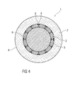
- FIGS. 1 . 2 and 4 to 8 schematically show various embodiments of a heat accumulator 1 for an adiabatic compressed air storage system for the purpose of energy storage, each in a cross-sectional view, wherein the Figures 2 . 5 . 6 and 8th each show only a section of the cross section of the heat accumulator 1.
- the show FIGS. 1 and 2 and 7 and 8 heat storage 1 with a load-bearing thermally insulating layer 2 and the FIGS. 4 to 6 Heat storage 1 with a non-load-bearing thermally insulating layer 2, in which therefore additional measures for load transfer are required.
- FIG. 3 shows schematically in plan view formed from concrete segments 5 separating layer 6 of FIG. 2 illustrated embodiment of the heat accumulator. 1
- the heat accumulator 1 includes in all embodiments the pressure vessel 4 and arranged in the pressure vessel 4 heat storage material 3, for example, ceramic, basalt or other stone material, for example as a bead, in gravel form or as a fracture material.
- This heat storage material 3 which is arranged in the form of a bed in the heat accumulator 1, is referred to below as the inventory pile.
- the pressure vessel 4 is designed, for example, in the form of a medicine capsule, ie it has a half-shell-shaped dome, at least at an upper end, preferably also at a lower end. Between the upper and the lower end of the pressure vessel 4 is tubular or hollow cylindrical.
- the dome or the domes can also be designed, for example, flattened and thus have only one or more curved transitions to the tubular or hollow-cylindrical region of the pressure vessel 4 in the marginal area.
- the thermally insulating layer 2 is substantially in the range of one arranged, for example, only interrupted by conveying lines for passing compressed air through the heat accumulator 1 and, if necessary, interrupted by additional KondensatabScience foundeden and / or described in more detail below on the pressure vessel wall 7 and / or fixed means for load transfer on the pressure vessel wall 7.
- this thermally insulating layer 2 may extend, for example, only over portions of the inner pressure vessel wall 7, for example not over the domes at the lower and upper end, but only over the shell-shaped or tubular region between the domes or only one or both domes and not over the jacket-shaped area or over the jacket-shaped area and only one of the two domes. It may also be selected in some areas other insulation structures.
- a cooling device can be arranged in the pressure vessel wall 7 and / or on an inner side of the pressure vessel wall 7, for example in the form of cooling channels or cooling lines, through which a liquid or gaseous coolant flows.
- This at least one thermally insulating layer 2 is formed from at least one insulating material, which has a pore content of 20 percent by volume to 80 percent by volume, preferably from 35 percent by volume to 70 percent by volume, and at temperatures of up to at least 650 ° C, but at least at temperatures up to at least 450 ° C, 500 ° C or 600 ° C, in solid state form, or the thermally insulating layer 2 comprises at least one such insulating material, which has a pore content of 20 volume percent to 80 volume percent, preferably from 35 volume percent to 70 volume percent, and at temperatures of up to at least 650 ° C, but at least at Temperatures of up to at least 450 ° C, 500 ° C or 600 ° C, in solid form.
- the at least one insulating material is expediently a puffed or foamed or naturally occurring material, for example blown clay, expanded glass, foam glass, expanded slate, brick chippings, metallurgical pumice, sintered hard coal fly ash, expanded perlite, natural pumice, lava varnish or tuff.
- the thermally insulating layer 2 may also be formed with a mixture of these materials and / or in different particle sizes. This insulating material is temperature resistant, even at the above high temperatures, which may occur in the heat accumulator 1, d. H. it remains firm and does not change its physical properties, or not significantly or not sufficiently detrimentally. The melting point of these materials is much higher than 650 ° C. Expanded clay is usually present in spherical form.
- the expanded clay is particularly advantageous since it is fired material which is resistant to hydration and has a compressibility and heat conductivity of the bed which can be adapted via its grain density or bulk density. Its properties are in opposite directions. A higher strength means a higher density and a higher thermal conductivity and thus a poorer insulation.
- the expanded clay should therefore be designed in such a way that a good compromise between its strength, density and thermal insulating properties is achieved.
- Expanded slate is also a fired material which, in contrast to expanded clay, has an irregular gravel-like grain shape.
- thermally insulating layer 2 Due to the use of said materials for the formation of the thermally insulating layer 2, it loses only slightly due to the preferably at least partially closed-cell or closed-pore structure and / or due to a preferably at least partially present sinter skin and / or due to a water absorption reducing coating even if the dew point undershoots on insulating effect, ie on thermal insulating effect, since preferably only pores between the respective material can be saturated with water. A saturation of the pore space between the Isoliermaterialp
- the at least one insulating material is expediently formed in ballast form and / or in spherical form and / or in a rounded shape. These forms are suitable both for the formation of the thermally insulating layer 2 as a bed, which can also be compacted, and as an aggregate for concrete. In the spherical shape or the rounded shape, a particularly good load transfer of loads of the heat storage material 3 over the thermally insulating layer 2 can be achieved, in particular in the formation of the thermally insulating layer 2 as a bed.
- the at least one thermally insulating layer 2, as in the FIGS. 1 . 2 and 4 to 6 is shown and will be explained in more detail below, formed as a bed of the insulating material.
- the material may have been compressed during the layer formation.
- this thermally insulating layer 2 which is designed as a charge conducts radial load components of the heat accumulator material 3 onto the load-transferring pressure container 4, more precisely onto the pressure vessel wall 7.
- Vertical loads of the heat storage material 3 are also forwarded from this thermally insulating layer 2 to the pressure vessel 4 or into a foundation of the pressure vessel 4.
- the formed as a bed of thermal insulating layer 2 of the insulating material is surprisingly able despite their low density in the situation.
- the bed of insulating material for forming the thermally insulating layer 2 is introduced in layers and mechanically compacted.
- the thermally insulating layer 2 can transmit higher loads.
- no complex shaping is required, but it can be filled with the bed or ballast layer any desired shape.
- the at least one thermally insulating layer 2 as in the FIGS. 7 and 8th is shown and below is explained in more detail, formed of concrete, which has the insulating material as an aggregate.
- the thermally insulating layer 2 is expediently designed in this embodiment as a concrete wall made of concrete with the insulating material as an additive. In comparison to an insulation with correspondingly shaped stones, no elaborate shaping is required, but any desired shape can be cast. In addition, support brackets for insulating bricks or load-bearing steel panels that protect non-pressure resistant insulating materials from the radial stresses from the bed of the heat storage material 3 can be avoided.
- FIG. 1 an embodiment of the heat accumulator 1 is shown in which insulating material for forming the thermally insulating layer 2 is expanded glass and / or foam glass, for example in ballast or spherical form.
- the insulating material may be, for example, another blown or foamed or naturally derived material having a void fraction of from 20% to 80% by volume, as described above.
- the thermally insulating layer 2 is formed here as a bed.
- expanded clay and / or expanded slate can also be used as insulating material.
- the insulating material may be in ballast, spherical and / or rounded form.
- the thermally insulating layer 2 from a compacted expanded glass ballast layer which permits both dew point undershooting, low density and low thermal conductivity, as well as loads from the storage inventory bed derives.
- the loads from the bed of the heat storage material 3, hereinafter also referred to as Speicherinventar thoroughlyung made uniform over a steel sheets formed by separating layer 6 and transferred to the thermally insulating layer 2, which is formed in this embodiment, for example, from expanded glass or foam glass ballast, ie Expanded glass or foam glass in ballast form.
- the radial load shares of the heat storage material 3 forwards the bed of expanded glass ballast / foam glass ballast on the load-bearing pressure vessel 4, which is preferably made of reinforced concrete or prestressed concrete.
- a pressure vessel 4 made of steel is also possible.
- the expanded glass ballast layer is installed in layers and mechanically compacted.
- the expanded glass ballast layer can transfer higher loads.
- the thermal insulation of a concrete pressure vessel of such a high-temperature heat storage with a bed of heat storage material 3 as a storage inventory is done with backfilling of the cavity between the pressure vessel wall 7 and the steel sheets, which form the separation layer 6, and separate the insulating charge of expanded glass or foam glass ballast of the thermally insulating layer 2 of the Speicherinventar structuriung , Due to the preferably at least partially closed-cell structure of the expanded glass ballast and / or foam glass ballast, the expanded glass ballast layer, which has preferably been compacted mechanically, loses little of its insulating effect when the dew point undershoots, since only the pores between the expanded glass ballast or the foam glass ballast can be saturated with water.
- a further training variant replaces the expanded glass ballast and / or foam glass ballast by a Blähglas thoroughlyung / foam glass bulk with round or rounded grain shape.
- Particularly advantageous in this design is the good load transfer of the Blähglas part emotions on all sides surrounding overpressure of up to 20 bar.
- no complicated shaping is required, but any desired shape can be filled with the expanded glass ballast layer / expanded glass filling.
- the mixing of the storage storage bulk material and the expanded glass ballast layer ie the mixing of the heat storage material 3 and the thermally insulating layer 2 with one another, is reliably prevented by the steel sheet of the separation layer 6.
- the steel sheets in a preferred embodiment can be connected to the concrete pressure vessel wall, ie to the pressure vessel wall 7 of the reinforced concrete or prestressed concrete pressure vessel 4, so that the expanded glass ballast layer can be installed and compacted without the storage inventory pile having to be installed ,
- steel beams 8 or steel bolts can be connected to a preferably existing steel lining of the concrete pressure vessel and forward the loads from the steel plates to the concrete pressure vessel wall.
- Such steel beams 8 and / or supports 9 for supporting the separating layer 6 with respect to the pressure vessel wall 7 are in the FIGS. 4 to 6 to the other embodiments shown.
- the supports 9 are expediently also formed of steel.
- the steel sheet separating the expanded glass ballast layer from the storage inventory fill of the heat storage material 3 is dispensed with and the storage inventory fill is installed in layers parallel to the expanded glass ballast insulation and compacted.
- the thermally insulating layer 2 There is a layer-wise introduction of the heat storage material 3 and the insulating material for the construction of the thermally insulating layer 2, without a separating layer 6 therebetween.
- the thermally insulating layer 2 For the expanded glass ballast insulation, d. H. the thermally insulating layer 2, a larger grain size is helpful for the drainage of condensate water amounts occurring and reduces the capillary suction between the individual grains / balls of Blähglas forung. This also applies to the formation of the thermally insulating layer 2 of one of the other of the above-mentioned insulating materials. Furthermore, such a larger grain size of the blown glass or other insulating materials reduces the water absorption of the individual balls / grains, if they are not or only partially closed-cell. On the other hand, the size of the individual grains / balls of Blähglas sectionung is limited to fill even irregular cavity areas of the Blähglasschuitz receiving cavity in the pressure vessel 4 safely and completely.
- the hollow space receiving the thermally insulating layer 2 in the form of the expanded glass filling is to be formed such that condensation occurring preferentially can flow downwards, preferably in the lower region of the heat accumulator 1 via the existing delivery lines for the compressed air and / or additional condensate discharge lines to be derived from the heat storage 1.
- FIG. 2 shows a further, particularly preferred embodiment of the heat accumulator 1.
- This embodiment is a particularly advantageous embodiment of in FIG. 1 illustrated embodiment.
- the thermally insulating layer 2 is load-bearing.
- the horizontal and vertical loads of the bed of heat storage material 3 are here, analogous to FIG. 1 , Removed by means of the thermally insulating layer 2.
- horizontal loads are transmitted via the thermally insulating layer 2 to the pressure vessel wall 7 and vertical loads are transmitted via the thermally insulating layer 2 to the pressure vessel 4 or a foundation of the pressure vessel 4. Due to this design of the heat accumulator 1 such that the thermally insulating layer 2 is load-bearing, no additional steel beams 8 and / or supports 9 are required for load transfer.
- the thermally insulating layer 2 is formed of the insulating material, which is present in ballast form and / or in spherical form and / or in rounded form. Its grain sizes can range from one millimeter to 60 mm. The advantages of the insulating material and the resulting from the respective grain size Voreile were already above in the in FIG. 1 illustrated embodiment explained.
- the insulating material is introduced into the space provided in the pressure vessel 4 and preferably compressed or at least precompressed, so that the load transfer by means of the thermally insulating layer 2 can be ensured.
- the insulating material for forming the thermally insulating layer 2 is also here, analogous to in FIG. 1 described example, preferably expanded clay, expanded glass, foam glass or expanded slate or another of the above materials, wherein a mixture of these materials for forming the thermally insulating layer 2 is possible.
- expanded clay is used to form the thermally insulating layer 2 in this embodiment.
- the separation layer 6 which is not formed in this embodiment of steel sheets, but which is designed as a concrete shell.
- this concrete shell as in FIG. 3 in a plan view of a heat storage material 3 side facing or on one of the thermally insulating layer 2 facing side of the formed as a concrete shell separating layer 6, formed of a plurality of superimposed and / or adjacent concrete segments 5.
- the separating layer 6 has a plurality of superimposed rows of concrete segments 5, wherein in each row a plurality of concrete segments 5 are arranged side by side and wherein the concrete segments 5 superimposed rows are offset by half a segment width to each other, as in a Forming a wall of concrete segments 5 is common.
- the concrete segments 5 may have, for example, on their underside connecting elements, for example in the form of formations of the respective concrete segment 5 or in the form of partially cast-in and partially protruding bolts, which in corresponding recesses 12 on an upper side arranged below concrete segments. 5 intervene, as in FIG. 3 shown.
- the concrete segments 5 are expediently designed as finished parts, for example cast, which are then arranged to form the separation layer 6 only in the pressure vessel 4 at the designated position between the space provided for the heat storage material 3 space and provided for the thermally insulating layer 2 space.
- the formation of the separating layer 6 as a concrete shell also allows the formation of the thermally insulating layer 2 before the heat storage material 3 is filled into the pressure vessel 4, since the separation layer 6 formed of concrete, even without steel beams 8 and supports 9, is sufficiently stable.
- expansion joints 13 are expediently provided at least between some of the adjacent concrete segments 5, as in FIG FIG. 2 shown.
- the concrete shell of the separating layer 6 of individual concrete segments 5 Due to the design of the concrete shell of the separating layer 6 of individual concrete segments 5, pressure equalization in the pressure vessel 4 is made possible via joints between adjacent concrete segments 5, so that a different pressure on a front side and a back side of the separating layer 6, which could lead to their destruction, is avoided .
- the concrete is preferably admixed with fibers, such as polyethylene (PE) or polypropylene (PP) or other materials. As a result, an overpressure in the pores of the concrete segments 5 is avoided.
- fibers such as polyethylene (PE) or polypropylene (PP) or other materials.
- the separating layer 6 fulfills the same function here as in FIG. 1 formed from steel sheets separating layer 6.
- the loads of the heat storage material 3 are made uniform over the separation layer 6 and the thermally insulating layer. 2 which transfers the radial load components into the pressure vessel 4 and the vertical load components, which are transferred by friction to the separating layer 6 and via this onto the thermally insulating layer 2, into a foundation of the pressure vessel 4.
- the separating layer 6 may be formed, for example, from bricks, d. H. as a brick wall. This also results in the already described for the formation of the separating layer 6 of concrete advantages.
- FIG. 4 shows a further embodiment of the heat accumulator 1.
- expanded glass, expanded clay, expanded glass and / or expanded slate or another of the abovementioned materials can also be used here, it being possible for the insulating material to be formed in ballast form and / or in spherical form and / or in rounded form.
- the heat insulation of the pressure vessel 4 of the heat accumulator 1 with a bed of heat storage material 3 takes place with backfilling of the cavity between the pressure vessel wall 7 and the steel sheets of the separating layer 6, which separate the insulating charge of expanded glass or foam glass of the thermally insulating layer 2 from the storage inventory of the heat storage material 3.
- the thermally insulating Due to the closed-cell structure of the expanded glass spheres, expanded glass gravel, foam glass spheres and / or the foam glass ballast, layer 2 loses only insignificant effect in the event of a dew point undershoot, since only the pores between the expanded glass spheres, the bluish glass gravel, the foam glass spheres or the foam glass gravel can be saturated with water.
- no complicated shaping is required, but any desired shape can be filled with the insulating filling.
- the steel beams 8 For load application of vertical loads on pressure or train the steel beams 8 need a non-displaceable in the vertical direction bearing at the bottom of the respective steel beam 8 at the load introduction into the foundation. Since the steel beams 8 are located at the edge of the insulation from the Blähglas thoroughlyung and have a thermally conductive connection to the steel sheets of the separating layer 6, they will experience significantly elevated temperatures up to the temperature in the storage inventory of the heat storage material 3. The temperature in the storage inventory heap may fluctuate cyclically. In order to limit the stresses in the steel beams 8 due to thermal expansion of the steel beams 8, the steel beams 8 above the foundation in the vertical direction must be slidably mounted in the supports 9 designed as rear anchors. At the same time, the steel girders 8 must be able to introduce tensile and compressive forces into the pressure vessel wall 7 via the rear anchors in the radial direction.
- the steel beams 8 In the circumferential direction, the steel beams 8 must be held immovably on the supports 9 designed as rear anchors in order to prevent skewing or tilting.
- a preferred embodiment of the rear anchoring is a kind of clamp that engages around a flange of the steel beam 8, absorbs tensile and compressive forces in the radial direction and prevents a shift in the circumferential direction.
- a free displacement of the steel beams 8 at the remindverank ceremoniessticianen is possible.
- the preferred restriction of direct contact between the steel girders 8 and the pressure vessel wall 7 to the contact points of the back anchors formed supports 9 makes it possible that in this preferred embodiment between the steel beams 8 and the pressure vessel wall 7 to the remindverank ceremoniessstellen also particles of Blähglas originallyung between the steel beams 8 and the pressure vessel wall 7 and provide insulation.
- the dimensions of the steel beams 8 are chosen so that they are smaller than the distance between the steel beam 8 and pressure vessel wall 7. This reduces the temperature gradients in the steel beams 8 and thus the thermally induced stresses in the steel beams 8.
- the steel sheets of the separating layer 6 experience thermal expansions.
- the steel sheets In order to keep the resulting stresses as low as possible or preferably to prevent completely, the steel sheets must be mounted on the steel beams 8 so that strains in the circumferential and vertical directions can be accommodated without forced voltages. Preferably, this can be done per steel sheet with four steel bolts with a fixed bearing, two slidable in one direction slots and a displaceable in two directions hole. Radial forces from the inventory bed of the heat storage material 3 can be transmitted via pressure between the steel sheets and the steel beams 8.
- the fortifications of the steel sheets on the steel beams 8, for example via steel bolts must be chosen so that the loads from the Blähglas sectionung be safely introduced into the steel beams 8 even without inventory pile.
- the mean grain size of the expanded glass bed must be chosen sufficiently large that the bed of heat storage material 3 any necessary open expansion joints 11 and pressure equalization holes can not penetrate or completely clog. In addition, a larger grain size is helpful for the drainage of condensate water volumes occurring and reduces capillary suction between the individual grains / balls of Blähglas sectionung.
- the size of the individual grains / spheres of the expanded glass filling is to be limited in order to reliably and completely fill even irregular regions of the cavity which receives the expanded glass filling. Smaller particle sizes are also more robust at the pressures occurring within the heat accumulator 1.
- Preferred particle sizes for the Blähglas sectionung have grain diameters greater than one millimeter and less than 16 mm, more preferably less than 8 mm.
- the cavity receiving the expanded glass bulk material is to be formed in such a way that thawing water preferably flows downwards, preferably in the lower region of the heat accumulator 1, via the existing delivery lines for the compressed air and / or additional condensate discharge lines from the heat accumulator 1.
- thawing water preferably flows downwards, preferably in the lower region of the heat accumulator 1, via the existing delivery lines for the compressed air and / or additional condensate discharge lines from the heat accumulator 1.
- FIG. 5 shows a further embodiment of the heat accumulator 1, in which the thermally insulating layer 2 itself is not load-bearing, but in which additional steel beams 8 and supports 9 are provided for load transfer.
- the separating layer 6 between the heat storage material 3 and the thermally insulating layer 2 is formed from one or more steel sheets in the form of one or more sheet metal plates and steel beams 8 and supports 9 with the pressure vessel wall 7 and the foundation of the pressure vessel 4 and the heat accumulator. 1 connected to derive the loads of the bed of the heat storage material 3 about it.
- the insulating material forming the thermally insulating layer 2 can here also be expanded clay, expanded glass, Foamed glass or expanded slate or another of the above materials, preferably expanded glass. A mixture of these materials for forming the thermally insulating layer 2 is possible. This insulating material can also be present here in ballast form and / or in spherical form and / or in rounded form.
- the steel beams 8 are formed for example as a double-T-carrier and anchored in the foundation of the heat accumulator 1.
- the supports 9 are not formed here merely as flat rear anchors on the pressure vessel wall 7, as in FIG. 4 shown, but as larger supports 9, which protrude correspondingly far into an installation space for the thermally insulating layer 2 in the pressure vessel 4.
- the steel beams 8 and supports 9 pass through the thermally insulating layer 2, ie are surrounded by the insulating material of the thermally insulating layer 2.
- the supports 9 are, as already for in FIG.
- a protective layer 10 is arranged between the pressure vessel wall 7 and the thermally insulating layer 2, to protect the pressure vessel wall 7 in order to reduce the friction and also to protect a cooling device for the pressure vessel wall 7 which may be arranged in this area.
- FIG. 6 shows a further embodiment of the heat accumulator 1.
- the steel beams 8 are replaced by a concrete wall, which also forms the separating layer 6.
- This separation layer 6 fulfills both its separation layer tasks to separate the thermally insulating layer 2 from the heat storage material 3 and to prevent mixing, as well as to FIG. 5 described tasks of Steel beams 8 in the form of load transfer of the loads of the heat storage material 3, wherein vertical loads are discharged through this designed as a concrete wall separating layer 6 in the foundation of the heat accumulator 1 and the pressure vessel 4 and horizontal, radial loads on the supports 9 and over this on the pressure vessel wall 7th
- the separating layer 6 can be, for example, analogous to the in FIG. 2 and 3 be illustrated separating layer 6, ie also in the form of individual concrete segments 5, preferably as finished parts, which are only to be positioned in the pressure vessel 4.
- the thermally insulating layer 2 itself is also here, analogous to in FIG. 5 shown example, not load-bearing.
- the supports 9 are also incorporated here in the thermally insulating layer 2, d. H. enclosed by their insulating material, which is filled in the space between the separating layer 6 and pressure vessel wall 7 and its protective layer 10.
- FIG. 7 shows a further embodiment of the heat accumulator 1.
- the thermally insulating layer 2 is formed of concrete, which comprises the insulating material as an aggregate, in this embodiment expanded glass, but alternatively or additionally are expanded clay, foam glass and / or expanded slate or another of the above materials as Aggregate for the concrete possible, here too in ballast form and / or in spherical form and / or in rounded form.
- expanded glass ie expanded glass concrete is formed with the expanded glass as an additive. With this expanded glass concrete, the thermally insulating layer 2 is formed as at least one wall.
- the thermal insulation of the preferably made of reinforced concrete or prestressed concrete pressure vessel 4 of the heat accumulator 1 with a bed of heat storage material 3 as a storage inventory is carried out with an insulating wall of the heat-insulating Blähglasbeton.
- This insulating wall forms the thermally insulating layer 2 between the heat storage material 3 and the pressure vessel wall 7.
- a protective layer 10 can be arranged as a release layer to reduce the friction.
- this preferably has expansion joints 11. These can be arranged radially.
- a design of the joint geometry is such that the joints are arranged radially offset, as in FIG. 7 shown.
- Each joint section does not extend in the radial direction over the complete wall thickness of the expanded glass concrete wall formed thermally insulating layer 2, but is offset in one or more sections in the circumferential direction so that strains in the circumferential direction can be absorbed without stress, direct convection flows over the formed as Blähglasbetonwand thermally insulating layer 2, however, be reduced.
- the thermally insulating layer 2 is formed from a plurality of segments 14, wherein the segments 14 are formed such that the expansion joints 11 between adjacent segments 14 in the radial direction of the heat accumulator 1 are stepped.
- a separating layer ie the protective layer 10
- the pressure vessel wall 7 and the formed as Blähglasbetonwand thermally insulating layer 2 which is preferably open-pored
- a uniformly distributed pressure preferably equal by appropriately trained expansion joints 11 the pressure is in the pores of the Storage inventory of the heat storage material 3 occurs. Excessive, non-uniform loading of the expanded glass concrete wall can thus be avoided.
- the cement matrix In order to prevent destruction of the cementitious stone matrix and thus the Blähglasbetonwand at a heating above the evaporation point of the water in the cement matrix, the cement matrix must have an open-cell pore structure with a sufficiently large water vapor permeability.
- a suitable water / cement value it is possible to obtain fibers to increase the permeability and / or creation of bonded pores.
- fibers of polyethylene which have a low melting point are preferably used.
- other fiber materials can be used which also ensure a sufficiently high water vapor permeability of the cement paste matrix.
- a suitably designed open-pored separating layer ie the protective layer 10 which preferably has additional cavities or pores, permits removal of the foam accumulating condensate preferred by gravity in low-lying areas of the heat accumulator 1, where it can be collected and discharged via existing conveyor lines or additional condensate lines from the heat storage 1.
- FIG. 8 shows a further embodiment of the heat accumulator 1.
- the thermally insulating layer 2 is also made of concrete here, which has the insulating material as an additive.
- the insulating material may be, for example expanded clay, expanded glass, foam glass or expandable slate or another of the above materials and mixed as an aggregate, for example in ballast and / or spherical and / or in rounded form the concrete. A combination of these materials as aggregates is possible.
- expanded clay is used as an additive in this embodiment.
- the illustrated example consists in that a separating layer 6, which is formed from concrete, is arranged here between the thermally insulating layer 2 and the bed of the heat storage material 3.
- This separating layer 6 made of concrete, for example, as in the Figures 2 . 3 and 6 be shown and described, ie formed of a plurality of concrete segments 5, which are preferably designed as precast elements and are to be arranged only in the pressure vessel 4.
- the load transfer of the vertical loads of the bed of heat storage material 3 can be done here directly on the separation layer 6 of concrete in the foundation of the heat accumulator 3 and the pressure vessel 4, as to FIG. 6 portrayed. Alternatively or additionally, this vertical load transfer can also take place via the thermally insulating layer 2.
Landscapes
- Engineering & Computer Science (AREA)
- Mechanical Engineering (AREA)
- General Engineering & Computer Science (AREA)
- Filling Or Discharging Of Gas Storage Vessels (AREA)
- Thermal Insulation (AREA)
Applications Claiming Priority (3)
| Application Number | Priority Date | Filing Date | Title |
|---|---|---|---|
| DE102012107062 | 2012-08-02 | ||
| DE102012107063 | 2012-08-02 | ||
| DE102012107124 | 2012-08-03 |
Publications (2)
| Publication Number | Publication Date |
|---|---|
| EP2711600A2 true EP2711600A2 (fr) | 2014-03-26 |
| EP2711600A3 EP2711600A3 (fr) | 2018-01-10 |
Family
ID=48915903
Family Applications (1)
| Application Number | Title | Priority Date | Filing Date |
|---|---|---|---|
| EP13179051.1A Withdrawn EP2711600A3 (fr) | 2012-08-02 | 2013-08-02 | Accumulateur thermique |
Country Status (1)
| Country | Link |
|---|---|
| EP (1) | EP2711600A3 (fr) |
Cited By (2)
| Publication number | Priority date | Publication date | Assignee | Title |
|---|---|---|---|---|
| CN117212673A (zh) * | 2023-07-11 | 2023-12-12 | 中国能源建设集团湖南省电力设计院有限公司 | 一种新型压缩空气储能地下人工硐室气库 |
| EP4311974A1 (fr) * | 2022-07-29 | 2024-01-31 | Karl-Heinz Martin Fischer | Réservoir sous pression d'hydrogène |
Citations (1)
| Publication number | Priority date | Publication date | Assignee | Title |
|---|---|---|---|---|
| EP1857614A2 (fr) | 2006-05-16 | 2007-11-21 | Ed. Züblin Aktiengesellschaft | Accumulateur thermique pour le stockage d'air comprimé adiabatique à des fins d'économies d'énergie |
Family Cites Families (4)
| Publication number | Priority date | Publication date | Assignee | Title |
|---|---|---|---|---|
| US3894372A (en) * | 1973-01-08 | 1975-07-15 | Baltek Corp | Cryogenic insulating panel system |
| DE3545622A1 (de) * | 1985-12-21 | 1987-06-25 | Aktionsgemeinschaft M U T E V | Waermespeicher |
| US20110100583A1 (en) * | 2009-10-29 | 2011-05-05 | Freund Sebastian W | Reinforced thermal energy storage pressure vessel for an adiabatic compressed air energy storage system |
| US20110127004A1 (en) * | 2009-11-30 | 2011-06-02 | Freund Sebastian W | Regenerative thermal energy storage apparatus for an adiabatic compressed air energy storage system |
-
2013
- 2013-08-02 EP EP13179051.1A patent/EP2711600A3/fr not_active Withdrawn
Patent Citations (1)
| Publication number | Priority date | Publication date | Assignee | Title |
|---|---|---|---|---|
| EP1857614A2 (fr) | 2006-05-16 | 2007-11-21 | Ed. Züblin Aktiengesellschaft | Accumulateur thermique pour le stockage d'air comprimé adiabatique à des fins d'économies d'énergie |
Cited By (2)
| Publication number | Priority date | Publication date | Assignee | Title |
|---|---|---|---|---|
| EP4311974A1 (fr) * | 2022-07-29 | 2024-01-31 | Karl-Heinz Martin Fischer | Réservoir sous pression d'hydrogène |
| CN117212673A (zh) * | 2023-07-11 | 2023-12-12 | 中国能源建设集团湖南省电力设计院有限公司 | 一种新型压缩空气储能地下人工硐室气库 |
Also Published As
| Publication number | Publication date |
|---|---|
| EP2711600A3 (fr) | 2018-01-10 |
Similar Documents
| Publication | Publication Date | Title |
|---|---|---|
| EP1857614B1 (fr) | Accumulateur thermique pour le stockage d'air comprimé adiabatique à des fins d'économies d'énergie | |
| DE102012219209A1 (de) | Wandelement für Gebäude in Fertigbauweise | |
| EP0146079A2 (fr) | Pièce réfractaire perméable aux gaz | |
| DE19526396A1 (de) | Baugrubenverbau, Verfahren zu seiner Herstellung sowie Baustoffgemenge dafür | |
| EP2610410A2 (fr) | Elément de construction pour l'isolation thermique | |
| DE102015112282A1 (de) | Verfahren und Vorrichtung zur thermischen Behandlung von Sand | |
| EP3022494A1 (fr) | Système de stockage d'énergie | |
| AT392692B (de) | Feuerfester, mit hohlraeumen versehener auskleidungsstein fuer industrieoefen | |
| EP2578981A1 (fr) | Accumulateur thermique | |
| DE2922555C2 (de) | Verfahren zur Herstellung eines feuerfesten Bauwerks | |
| EP1156022B1 (fr) | Mélange de béton à résistance au feu accrue | |
| DE69707315T2 (de) | Verfahren zur Herstellung von keramischen Produkten in Form von Bauschichten aus Erde oder vorgefertigten Bauelementen | |
| DE2530432A1 (de) | Flachgewoelbe fuer tunneloefen | |
| DE3141726C2 (de) | Verfahren zur Vermeidung bzw. Reduzierung der Wechselwirkungen und deren Folgen bei einem Kontakt von heißem, flüssigem, metallischem Natrium mit Beton | |
| AT411106B (de) | Wagen zum transport von keramikrohlingen | |
| DE3231736C2 (de) | Ummantelung zur Isolierung eines gekühlten Gleit-, Trag- oder Querrohres in einer Feuerungsanlage | |
| DE102015011742A1 (de) | Tunnelofenwagen oder -schlitten und Verfahren zu dessen Herstellung sowie Tunnelofen mit einem derartigen Tunnelofenwagen oder -schlitten | |
| EP1660833A2 (fr) | Pierre servant de bouclier thermique pour garnir une paroi de chambre de combustion, chambre de combustion et turbine a gaz correspondantes | |
| DE19942965A1 (de) | Wärmedämmendes, tragendes Bauelement | |
| WO2007042056A1 (fr) | Cavité à cassettes d'un four pit, brique moulée pour cette cavité et procédé pour fabriquer cette brique moulée | |
| EP1701122B1 (fr) | Plaque réfractaire bi-couche et son procédé de fabrication | |
| EP3663475B1 (fr) | Dispositif d'isolement thermique entre un mur de bâtiment bétonné et un plancher, ainsi que procédé de fabrication | |
| DE102009021606A1 (de) | Mineralischer Stoff | |
| DE2412749C2 (de) | Rauchgassammelkanal an regenerativ beheizten Verkokungsöfen | |
| AT217078B (de) | Winkelstützmauer zum Abstützen von aufgeschütteten Erdmassen, insbesondere beim Straßenbau sowie hiebei zu verwendende Steine und Zugstangen |
Legal Events
| Date | Code | Title | Description |
|---|---|---|---|
| PUAI | Public reference made under article 153(3) epc to a published international application that has entered the european phase |
Free format text: ORIGINAL CODE: 0009012 |
|
| AK | Designated contracting states |
Kind code of ref document: A2 Designated state(s): AL AT BE BG CH CY CZ DE DK EE ES FI FR GB GR HR HU IE IS IT LI LT LU LV MC MK MT NL NO PL PT RO RS SE SI SK SM TR |
|
| AX | Request for extension of the european patent |
Extension state: BA ME |
|
| PUAL | Search report despatched |
Free format text: ORIGINAL CODE: 0009013 |
|
| AK | Designated contracting states |
Kind code of ref document: A3 Designated state(s): AL AT BE BG CH CY CZ DE DK EE ES FI FR GB GR HR HU IE IS IT LI LT LU LV MC MK MT NL NO PL PT RO RS SE SI SK SM TR |
|
| AX | Request for extension of the european patent |
Extension state: BA ME |
|
| RIC1 | Information provided on ipc code assigned before grant |
Ipc: F17C 1/00 20060101AFI20171204BHEP |
|
| 17P | Request for examination filed |
Effective date: 20180706 |
|
| RBV | Designated contracting states (corrected) |
Designated state(s): AL AT BE BG CH CY CZ DE DK EE ES FI FR GB GR HR HU IE IS IT LI LT LU LV MC MK MT NL NO PL PT RO RS SE SI SK SM TR |
|
| STAA | Information on the status of an ep patent application or granted ep patent |
Free format text: STATUS: THE APPLICATION IS DEEMED TO BE WITHDRAWN |
|
| 18D | Application deemed to be withdrawn |
Effective date: 20200303 |