EP2711672A1 - Détecteur d'écoulement - Google Patents
Détecteur d'écoulement Download PDFInfo
- Publication number
- EP2711672A1 EP2711672A1 EP12185929.2A EP12185929A EP2711672A1 EP 2711672 A1 EP2711672 A1 EP 2711672A1 EP 12185929 A EP12185929 A EP 12185929A EP 2711672 A1 EP2711672 A1 EP 2711672A1
- Authority
- EP
- European Patent Office
- Prior art keywords
- fluid
- heater
- flow direction
- sections
- flow
- Prior art date
- Legal status (The legal status is an assumption and is not a legal conclusion. Google has not performed a legal analysis and makes no representation as to the accuracy of the status listed.)
- Ceased
Links
Images


Classifications
-
- G—PHYSICS
- G01—MEASURING; TESTING
- G01F—MEASURING VOLUME, VOLUME FLOW, MASS FLOW OR LIQUID LEVEL; METERING BY VOLUME
- G01F1/00—Measuring the volume flow or mass flow of fluid or fluent solid material wherein the fluid passes through a meter in a continuous flow
- G01F1/68—Measuring the volume flow or mass flow of fluid or fluent solid material wherein the fluid passes through a meter in a continuous flow by using thermal effects
- G01F1/684—Structural arrangements; Mounting of elements, e.g. in relation to fluid flow
-
- G—PHYSICS
- G01—MEASURING; TESTING
- G01F—MEASURING VOLUME, VOLUME FLOW, MASS FLOW OR LIQUID LEVEL; METERING BY VOLUME
- G01F1/00—Measuring the volume flow or mass flow of fluid or fluent solid material wherein the fluid passes through a meter in a continuous flow
- G01F1/68—Measuring the volume flow or mass flow of fluid or fluent solid material wherein the fluid passes through a meter in a continuous flow by using thermal effects
- G01F1/684—Structural arrangements; Mounting of elements, e.g. in relation to fluid flow
- G01F1/6845—Micromachined devices
Definitions
- the present patent application relates to a flow detector according the preamble of claim 1 or 7.
- Flow detectors are well known from the prior art.
- Flow detectors comprise a substrate providing a sensing surface that can be brought into direct or indirect contact with a fluid, a heater provided on the sensing surface, and temperature sensors provided on the sensing surface on both sides of the heater.
- a flow detector is known from EP 1 124 114 A1 .
- the heater and the temperature sensors are all comb-tooth shaped.
- a first flow detector according to the present invention is defined in the claim 1.
- the temperature sensors of the first flow detector according to the present invention are formed in a rectangular spiral shape having first sections running parallel to a flow direction of the fluid and second sections running perpendicular to the flow direction of the fluid.
- a second flow detector according to the present invention is defined in the claim 7.
- the temperature sensors of the second flow detector according to the present invention are formed in a two-dimensional space-filling curve shape having first sections running parallel to a flow direction of the fluid and second sections running perpendicular to the flow direction of the fluid.
- Both flow detectors according to the present invention have improved measuring properties compared to flow detectors which make use of comb-tooth shaped temperature sensors.
- the flow detectors according to the present invention provide a more accurate flow measurement.
- the flow detectors according to the present invention provide more homogeneous distribution of the temperature sensors and the heater versus the flow in particular when the flow could be not laminar but more turbulent. So, the flow detectors according to the present invention have improved measuring properties especially for turbulent flow conditions of the fluid.
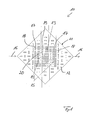
- Figure 1 shows an embodiment of a mass flow detector 10 according to the present invention.
- the flow detector 10 comprises a substrate 11 providing a sensing surface 12 that can be brought into direct or indirect contact with a fluid being subject of a flow measurement.
- a heater 13 is provided on the sensing surface 12 of the substrate 11.
- temperature sensors 14, 15 are provided on the sensing surface 12 of the substrate 11, whereby the temperature sensor 14 is positioned on a first side of the heater 13 and whereby the temperature sensor 15 is positioned on a second side of the heater 13.
- Figure 1 further illustrates the flow direction 16 of the fluid being subject of a flow measurement.
- the temperature sensor 14 is positioned seen in this flow direction upstream of the heater 13 and the temperature sensor 15 is positioned seen in this flow direction downstream of the heater 13.
- the temperature sensors 14, 15 are formed in a two-dimensional space-filling curve shape having first sections 17 running parallel to a flow direction of the fluid and second sections 18 running perpendicular to the flow direction of the fluid.
- the heater 13 is formed in a two-dimensional space-filling curve shape having first sections 19 running parallel to a flow direction of the fluid and second sections 20 running perpendicular to the flow direction of the fluid.
- the space-filling curve shape of the temperature sensors 14, 15 are Peano curves. These Peano curves of the temperature sensors 14, 15 have at least a second order of iteration.
- the space-filling curve of the heater 13 is a Peano curve.
- the Peano curve of the heater 13 has the same iteration order like the Peano curves of temperature sensors 14, 15.
- the temperature sensors 214, 215 provided on the sensing surface 212 of the substrate 211 of the flow detector 210 are formed in a two-dimensional space-filling curve shape having first sections 217 running parallel to a flow direction of the fluid and second sections 218 running perpendicular to the flow direction of the fluid.
- the heater 213 is formed in a rectangular spiral shape having first sections 219 running parallel to a flow direction 216 of the fluid and second sections 220 running perpendicular to the flow direction 216 of the fluid.
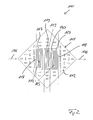
- Figure 2 shows another embodiment of a mass flow detector 110 according to the present invention.
- the flow detector 110 comprises a substrate 111 providing a sensing surface 112 that can be brought into direct or indirect contact with a fluid being subject of a flow measurement.
- a heater 113 is provided on the sensing surface 112 of the substrate 111.
- temperature sensors 114, 115 are provided on the sensing surface 112 of the substrate 111, whereby the temperature sensor 114 is positioned on a first side of the heater 113 and whereby the temperature sensor 115 is positioned on a second side of the heater 113.
- Figure 2 further illustrates the flow direction 116 of the fluid being subject of a flow measurement.
- the temperature sensor 114 is positioned seen in this flow direction upstream of the heater 113 and the temperature sensor 115 is positioned seen in this flow direction downstream of the heater 113.
- the temperature sensors 114, 115 are formed in a rectangular spiral shape having first sections 117 running parallel to a flow direction 116 of the fluid and second sections 118 running perpendicular to the flow direction 116 of the fluid.
- the heater 113 is formed in a rectangular spiral shape having first sections 119 running parallel to a flow direction 116 of the fluid and second sections 120 running perpendicular to the flow direction 116 of the fluid.
- the temperature sensors 314, 315 provided on the sensing surface 312 of the substrate 311 of the flow detector 310 are formed in a rectangular spiral shape having first sections 317 running parallel to a flow direction of the fluid and second sections 318 running perpendicular to the flow direction of the fluid.
- the heater 313 is formed in a two-dimensional space-filling curve shape having first sections 319 running parallel to a flow direction 316 of the fluid and second sections 320 running perpendicular to the flow direction 316 of the fluid.
- the space-filling curve shape of the heater 313 is a Peano curve.
- the Peano curve of the heater 313 at least a second order of iteration.
- each temperature sensor 114, 115, 314, 315 is formed as one single rectangular spiral.
- the respective heater 113, 213 is formed as one single rectangular spiral.
- the heaters can also be formed in a comb-tooth shape.
- Each temperature sensor 14, 15, 114, 115, 214, 215, 314, 315 and each heater 13, 113, 213, 313 of the shown embodiments comprises a width in the flow direction of the fluid of one unit and a height perpendicular to the flow direction of the fluid of three units high. So, the width:height ratio is 1:3. Preferably the width/height ratio is in a range of 1:2 to 1:4, most preferably the width/height ratio is in a range of 1:2.5 to 1:3.5.
Landscapes
- Physics & Mathematics (AREA)
- Fluid Mechanics (AREA)
- General Physics & Mathematics (AREA)
- Measuring Volume Flow (AREA)
Priority Applications (1)
| Application Number | Priority Date | Filing Date | Title |
|---|---|---|---|
| EP12185929.2A EP2711672A1 (fr) | 2012-09-25 | 2012-09-25 | Détecteur d'écoulement |
Applications Claiming Priority (1)
| Application Number | Priority Date | Filing Date | Title |
|---|---|---|---|
| EP12185929.2A EP2711672A1 (fr) | 2012-09-25 | 2012-09-25 | Détecteur d'écoulement |
Publications (1)
| Publication Number | Publication Date |
|---|---|
| EP2711672A1 true EP2711672A1 (fr) | 2014-03-26 |
Family
ID=47002667
Family Applications (1)
| Application Number | Title | Priority Date | Filing Date |
|---|---|---|---|
| EP12185929.2A Ceased EP2711672A1 (fr) | 2012-09-25 | 2012-09-25 | Détecteur d'écoulement |
Country Status (1)
| Country | Link |
|---|---|
| EP (1) | EP2711672A1 (fr) |
Citations (7)
| Publication number | Priority date | Publication date | Assignee | Title |
|---|---|---|---|---|
| JPH10185644A (ja) * | 1996-10-31 | 1998-07-14 | Ricoh Co Ltd | 感熱式フローセンサ |
| US5892150A (en) * | 1997-01-10 | 1999-04-06 | Hitachi, Ltd. | Air flow measuring element and air flow measuring apparatus therewith |
| EP1124114A1 (fr) | 1999-06-14 | 2001-08-16 | Yamatake Corporation | Detecteur de vitesse d'ecoulement |
| US6871534B1 (en) * | 1998-12-21 | 2005-03-29 | Mitsubishi Denki Kabushiki Kaisha | Flow rate measuring device |
| EP1643219A2 (fr) * | 2004-09-28 | 2006-04-05 | Hitachi, Ltd. | Capteur de débit de type thermique |
| EP1865295A1 (fr) * | 2006-06-06 | 2007-12-12 | Honeywell International Inc. | Transducteur de capteur de flux avec éléments de pont de Wheatstone à double spirale |
| US20100213590A1 (en) * | 2009-02-25 | 2010-08-26 | Conexant Systems, Inc. | Systems and Methods of Tamper Proof Packaging of a Semiconductor Device |
-
2012
- 2012-09-25 EP EP12185929.2A patent/EP2711672A1/fr not_active Ceased
Patent Citations (7)
| Publication number | Priority date | Publication date | Assignee | Title |
|---|---|---|---|---|
| JPH10185644A (ja) * | 1996-10-31 | 1998-07-14 | Ricoh Co Ltd | 感熱式フローセンサ |
| US5892150A (en) * | 1997-01-10 | 1999-04-06 | Hitachi, Ltd. | Air flow measuring element and air flow measuring apparatus therewith |
| US6871534B1 (en) * | 1998-12-21 | 2005-03-29 | Mitsubishi Denki Kabushiki Kaisha | Flow rate measuring device |
| EP1124114A1 (fr) | 1999-06-14 | 2001-08-16 | Yamatake Corporation | Detecteur de vitesse d'ecoulement |
| EP1643219A2 (fr) * | 2004-09-28 | 2006-04-05 | Hitachi, Ltd. | Capteur de débit de type thermique |
| EP1865295A1 (fr) * | 2006-06-06 | 2007-12-12 | Honeywell International Inc. | Transducteur de capteur de flux avec éléments de pont de Wheatstone à double spirale |
| US20100213590A1 (en) * | 2009-02-25 | 2010-08-26 | Conexant Systems, Inc. | Systems and Methods of Tamper Proof Packaging of a Semiconductor Device |
Similar Documents
| Publication | Publication Date | Title |
|---|---|---|
| Kumar et al. | Experimental investigation on heat transfer and fluid flow characteristics of air flow in a rectangular duct with Multi v-shaped rib with gap roughness on the heated plate | |
| EP2085754A3 (fr) | Capteur de débit avec résistance de film métallique | |
| EP2693181B1 (fr) | Sonde de température totale | |
| CN101887041B (zh) | 机械压力作用下接触热阻测量装置及测量方法 | |
| FI2912455T3 (fi) | Fluidilaite | |
| EP3546847A3 (fr) | Capteur de temperature et contrôle de température liquide | |
| NZ741880A (en) | Liquid level indicating | |
| EP2491353B1 (fr) | Procédé de mesure du débit et de la direction d'écoulement d'un fluide, et débitmètre du type thermique | |
| EP3237851B1 (fr) | Débitmètre du type thermique | |
| EP1944585A3 (fr) | Capteur de fluide de type thermique et son procédé de fabrication | |
| SG10201805383XA (en) | Method and system for multi-phase flow measurement | |
| WO2014064026A3 (fr) | Débitmètre de masse d'air équipé d'un élément détecteur | |
| EP4502552A3 (fr) | Dispositif de détection d'écoulement | |
| EP1484584A3 (fr) | Debitmetre a air de type thermique | |
| WO2011083393A3 (fr) | Système pour mesurer la vitesse d'écoulement d'un fluide | |
| WO2012049417A3 (fr) | Dispositif et methode de determination de la conductivite et/ou de la capacite thermique d ' une paroi | |
| US9778218B2 (en) | Steam wetness measurement device | |
| Mondloe et al. | Experimental investigation of heat transfer and fluid flow in solar air heaters using transverse wire rib roughness with variable gaps | |
| CN111796112B (zh) | 风传感器壳体和包括这种壳体的风传感器 | |
| Afanasiev et al. | Rectangular ribs in turbulent boundary layer on the initially smooth surface | |
| KR20130109483A (ko) | 열량형 질량유량계 센서 | |
| CN205049158U (zh) | 一种微纳电极 | |
| EP2811266B1 (fr) | Capteur d'écoulement de fluide | |
| Benissan et al. | Experimental measurement of Nusselt number correlations on flat plate and NACA 0010 section surfaces | |
| CN104155022A (zh) | 一种防爆风机用铠装热电阻 |
Legal Events
| Date | Code | Title | Description |
|---|---|---|---|
| PUAI | Public reference made under article 153(3) epc to a published international application that has entered the european phase |
Free format text: ORIGINAL CODE: 0009012 |
|
| AK | Designated contracting states |
Kind code of ref document: A1 Designated state(s): AL AT BE BG CH CY CZ DE DK EE ES FI FR GB GR HR HU IE IS IT LI LT LU LV MC MK MT NL NO PL PT RO RS SE SI SK SM TR |
|
| AX | Request for extension of the european patent |
Extension state: BA ME |
|
| 17P | Request for examination filed |
Effective date: 20140905 |
|
| RBV | Designated contracting states (corrected) |
Designated state(s): AL AT BE BG CH CY CZ DE DK EE ES FI FR GB GR HR HU IE IS IT LI LT LU LV MC MK MT NL NO PL PT RO RS SE SI SK SM TR |
|
| 17Q | First examination report despatched |
Effective date: 20160812 |
|
| 18R | Application refused |
Effective date: 20170522 |