EP2712021B1 - Antenne pour un appareil d'écriture/de lecture pour agencements RFID et appareil d'écriture/de lecture pour le fonctionnement avec une antenne externe - Google Patents
Antenne pour un appareil d'écriture/de lecture pour agencements RFID et appareil d'écriture/de lecture pour le fonctionnement avec une antenne externe Download PDFInfo
- Publication number
- EP2712021B1 EP2712021B1 EP12185408.7A EP12185408A EP2712021B1 EP 2712021 B1 EP2712021 B1 EP 2712021B1 EP 12185408 A EP12185408 A EP 12185408A EP 2712021 B1 EP2712021 B1 EP 2712021B1
- Authority
- EP
- European Patent Office
- Prior art keywords
- antenna
- read
- ant
- slg
- write unit
- Prior art date
- Legal status (The legal status is an assumption and is not a legal conclusion. Google has not performed a legal analysis and makes no representation as to the accuracy of the status listed.)
- Not-in-force
Links
Images


Classifications
-
- G—PHYSICS
- G06—COMPUTING OR CALCULATING; COUNTING
- G06K—GRAPHICAL DATA READING; PRESENTATION OF DATA; RECORD CARRIERS; HANDLING RECORD CARRIERS
- G06K7/00—Methods or arrangements for sensing record carriers, e.g. for reading patterns
- G06K7/10—Methods or arrangements for sensing record carriers, e.g. for reading patterns by electromagnetic radiation, e.g. optical sensing; by corpuscular radiation
- G06K7/10009—Methods or arrangements for sensing record carriers, e.g. for reading patterns by electromagnetic radiation, e.g. optical sensing; by corpuscular radiation sensing by radiation using wavelengths larger than 0.1 mm, e.g. radio-waves or microwaves
- G06K7/10316—Methods or arrangements for sensing record carriers, e.g. for reading patterns by electromagnetic radiation, e.g. optical sensing; by corpuscular radiation sensing by radiation using wavelengths larger than 0.1 mm, e.g. radio-waves or microwaves using at least one antenna particularly designed for interrogating the wireless record carriers
-
- H—ELECTRICITY
- H01—ELECTRIC ELEMENTS
- H01Q—ANTENNAS, i.e. RADIO AERIALS
- H01Q1/00—Details of, or arrangements associated with, antennas
- H01Q1/12—Supports; Mounting means
- H01Q1/22—Supports; Mounting means by structural association with other equipment or articles
- H01Q1/2208—Supports; Mounting means by structural association with other equipment or articles associated with components used in interrogation type services, i.e. in systems for information exchange between an interrogator/reader and a tag/transponder, e.g. in Radio Frequency Identification [RFID] systems
- H01Q1/2216—Supports; Mounting means by structural association with other equipment or articles associated with components used in interrogation type services, i.e. in systems for information exchange between an interrogator/reader and a tag/transponder, e.g. in Radio Frequency Identification [RFID] systems used in interrogator/reader equipment
Definitions
- the invention relates to an antenna for a read / write device for RFID devices according to the preamble of patent claim 1, a read / write device for RFID devices according to the preamble of patent claim 9, a system of a read / write device for RFID devices and an external antenna according to the preamble of claim 10, and a method for adapting a read / write device for RFID devices to an external antenna according to the preamble of claim 11.
- Read / write devices for RFID devices eg in the UHF frequency band , are often operated with external antennas, especially in such arrangements in which an internal antenna alone is not sufficient to cover a required radio range.
- a loading door in logistics for better radio coverage with four antennas are equipped, all four antennas to a single read / write device ("Reader") are connected, wherein in the read / write device, for example by means of a switching matrix, an alternate operation of different antennas is realized.
- Reader read / write device
- a user must carefully parameterize the antenna lines and antennas used in the read / write device during the configuration of the read / write device.
- the antenna may suffer losses, which may or may be compensated by a higher transmission power of the read / write device.
- the desired or allowed radiation power on the other hand, in a mis-configuration, for example, at one high set cable attenuation, if necessary may exceed the permissible radiation power.
- the publication JP2011139342A - Tadashi shows the use of a reference RFID data carrier to compensate for the line loss of a transmission power using an antenna with an antenna line, which is provided when using an antenna with an antenna cable with a different length Adjusting the transmission power based on the difference in line loss calculated on the basis of the difference in length.
- the publication DE102009045186A1 Tietke et al. “RFID reader, RFID system, method for controlling the transmission power of an RFID reader and computer program product” shows an HF RFID reader with inductive coupling, the reader with a measuring device for detecting the field strength of the emitted alternating magnetic field and for controlling the transmission power having.
- the publication US2004 / 0212493A1 Stilp shows an arrangement with eienr plurality of RFID transponders, the transmission power of the RFID reader can be adapted to ensure communication depending on the situation.
- the publication US2004 / 257284 Rada et al. “Detachable 802.11A antenna detection” shows a detachable antenna for a radio comprising means for measuring power and for identifying identification data.
- RFID reader device shows an RFID reader that can connect to a detachable antenna.
- the antenna has a data carrier with stored antenna characteristics, which the reader uses to adjust the transmission parameters accordingly.
- the antennas provided for the RFID arrangements with a data memory readable by read / write devices, wherein in the data memory information about the type of antenna or the technical characteristics of the antennas (eg the antenna gain).
- the antenna should furthermore be configured in such a way that it ensures a configuration of at least the maximum transmission power of the read / write device independently of the antenna line used or its technical properties (eg damping).
- the invention provides that a high-frequency signal fed into the antenna from the read / write device via the antenna line, at least in the case for which a threshold or threshold is reached or exceeded, to a corresponding message of the antenna to the write / Reader leads, whereby the read / write device is able to detect line losses or the like or compensate.
- the object is achieved in particular by an antenna according to claim 1, by a read / write device according to claim 9, by a system according to claim 10 and by a method according to claim 11.
- the solution of the task provides an antenna for a read / write device for RFID arrangements, wherein the antenna is provided for connection to an external antenna terminal of the read / write device by means of an antenna line.
- the antenna is equipped with a data memory with type information and / or with property information, wherein the content of the data memory is readable by the read / write device, and wherein the antenna has a measuring device for determining at least a value of the field strength or power of a in the antenna of having the read / write device fed high-frequency signal, wherein the antenna comprises means for informing the read / write device on the achievement or exceeding of the at least one value.
- the antenna has means for transmitting the content of the data memory and for informing the read / write device of reaching or exceeding the at least one value by means of a clocked short-circuiting of the antenna line, wherein the antenna for bitwise transmission of the information to be transmitted by the clocked shorting is configured ,
- a so-called "plug-and-play" solution can be achieved in which a user does not open the antenna or the antenna line must configure related parameters on the read / write device.
- such an antenna can be used with a read / write device, which on the part of its hardware equipment the State of the art can correspond; at most on the firmware or application level, a read / write device for automatic configuration must be set up with the antenna according to the invention.
- the object is further achieved by a read / write device for RFID arrangements, wherein the read / write device for adjusting a transmission power and / or for determining a maximum transmission power depending on the type or characteristics of the antenna used and in dependence of the attenuation of a used antenna line is set up.
- the read / write device for reading a type or property information from the antenna and for automatic consideration of the attenuation by receiving information about reaching or exceeding at least one value for the field strength or power received in the antenna from the read / write device High-frequency signal and set in operation operation of this at least one value to a relative or absolute value for the case of the read / write device emitted high-frequency signal.
- the read / write device is configured to receive the content of the data memory transmitted bit by bit by the antenna by means of a clocked short-circuit of the antenna line and the information about reaching or exceeding the at least one value, wherein the read / write device is used to determine the maximum or one to be used Transmission power based on the type or property information and based on the relationship between the power of the emitted high-frequency signal and the information about the at least one value is set.
- Such a read / write device is capable of automatically configuring the antenna and line parameters in conjunction with a correspondingly configured antenna.
- the object is further achieved by a system comprising a read / write device for RFID devices and an external antenna connected by means of a connection cable, wherein the system is set up to automatically adapt the read / write device to the antenna and the antenna line used.
- the system is formed from the previously described read / write device and the previously described antenna.
- Such a system allows an automatic Configuration of the antenna and line parameters in the read / write device.
- the object is also achieved by a method for adapting a read / write device for RFID arrangements to an external antenna connected by means of a connecting line.
- At least one type information and / or at least property information is read out from the antenna by the read / write device, wherein at least one high-frequency signal is emitted by the read / write device and fed into the antenna, wherein information about reaching or is received from the antenna Exceeding at least one value of the radio frequency signal detected in the antenna is transmitted bit by bit to the read / write device by means of a clocked short circuit of the antenna line, and wherein the read / write device based on the type information and / or the property information of the antenna and the reference between the relative or absolute power output and the at least one value performs an adaptation, in particular a maximum transmission power.
- the antenna for transmitting the contents of the data memory and for informing the read / write device of reaching or exceeding the at least one value uses the "modulated backscatter” communication method according to an RFID protocol, thereby achieving that for the one used Read / write device no further, separate communication protocol must be implemented.
- the method of "modulated backscattering” is also known in the field of RFID technology as “backscattering” or "load modulation”.
- a threshold activation threshold, "wake-up level”
- a data memory eg RFID transponder
- the antenna has a power sensor coupled to a radio-frequency line or to a radiation element, which is set up and connected in such a way that upon reaching or exceeding a minimum value of field strength or power (FIG.
- the read / write device into the antenna fed field strength or power) of the data memory or the transmission of the information is activated, wherein the minimum power is used as the at least one value.
- a series dispersion or a temperature dependence of the response threshold of the RFID transponder no longer plays a role.
- the at least one value ie the activation value of the power detector or the response threshold of the RFID transponder
- the at least one value ie the activation value of the power detector or the response threshold of the RFID transponder
- the at least one value are stored in the data memory, or alternatively from a type information that is stored in the data memory, are obtained, for example, based on an access on tables or databases. It is also possible to store response values for different frequencies or temperatures.
- the activation of the data memory or the transmission of the information can also be initiated in the same way.
- the method and arrangements described below is based on the problem that an antenna with a coaxial cable is to be connected as an antenna line to an RFID read / write device, wherein the antenna type or the technical properties of the antenna are determined automatically by the read / write device should be determined and also for the read / write device automatically the cable loss or (maximum allowable) transmission power of the antenna, by the information about the antenna type / antenna characteristics and the information about the cable loss or the given transmission power high frequency power available in the antenna. For example, it should be ensured that the maximum permitted EIRP (Equivalent Isotropically Radiated Power) is not exceeded.
- EIRP Equivalent Isotropically Radiated Power
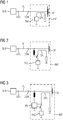
- FIG. 1 is schematically shown an arrangement (system) of a read / write device SLG and an antenna ANT, which are connected to each other by means of a connecting cable AL (coaxial cable), which is connected to connectors CON (Connectors).
- the antenna has a radiation element SE, at which the radio-frequency signals are radiated or received.
- the radiating element SE in short: radiator, corresponds the prior art and may for example correspond to a "patch antenna" (planar radiator).
- the antenna ANT shown here corresponds in terms of its RF characteristics of an antenna from the prior art.
- an RFID transponder chip TAG (short: transponder chip) is coupled via a coupler CPL as a data memory.
- a power divider or a similar connection of the RFID transponder to the high-frequency path of the antenna ANT can also be selected.
- a coupling to the radiation element SE can take place.
- type information and / or technical information about the properties of the antenna ANT and especially about the properties of the radiation element SE are stored. Specifically, this is a type designation, such as ANT-0815, and a measure of the antenna gain, for example, 3 dBi specified.
- ANT-0815 a measure of the antenna gain
- 3 dBi a measure of the antenna gain
- other technical parameters and further type information can also be stored in the data memory.
- the data can be stored, for example, in tabular form as a function of parameters such as operating frequency and temperature.
- the RFID transponder is designed such that it is "compatible" with the used read / write device SLG, ie can be read by means of this device.
- this begins with detection cycles ("Inventories"), wherein periodically a modulated high-frequency carrier wave ("interrogation message") is emitted according to the RFID protocol used.
- an identification number or range of identification of such RFID transponders TAG may each specify an identification number or range of identification of such RFID transponders TAG that are provided to "respond" to the polling cycles.
- the RFID transponders provided for antennas ANT each have a specific identification number or belong to a specific area (number range) of identification numbers. It can thus be ensured that the RFID transponder TAG used for the configuration no longer responds to further detection cycles during subsequent, ongoing operation and thus interferes with the productive operation.
- the read / write device SLG starts the consecutive polling cycles with a very low, minimum transmission power. This transmission power is successively increased with subsequent polling cycles. As soon as the high-frequency power introduced via the coupler CPP into the RFID transponder TAG is sufficient for the operation of the transponder TAG ("wake-up"), the transponder TAG responds so that its data memory is provided with the information, that is to say type information and / or property information Read / write device SLG is read out.
- This "threshold" whose height is stored in an advantageous embodiment in the RFID transponder TAG (transponder chip) as a further information or can be determined on the basis of a type information and thus can be transmitted to the read / write device, from the write / Reader with the transmit power used in the first successful capture cycle;
- the radiated or emitted high-frequency power can be used either as an absolute value (eg 5 mW) or as a relative value (eg 25%) of a nominal value.
- the "response threshold" of the RFID transponder TAG can be an absolute value (eg, 2 mW) or even a relative value (eg, 30%), the relative value then being related, for example, to a maximum radiated power (EIRP) of an antenna with a gain of 0 dBi determined in a standard, the antenna gain being one of the antenna retrieved information from the read / write device SLG to determine the maximum possible or allowed transmission power must be considered.
- EIRP maximum radiated power
- the RFID transponder TAG can be switched to "silent" during the following transactions during operation in the radio field of the antenna ANT in order not to disturb the normal operation of the read / write device SLG.
- ID's a number range of RFID serial numbers
- FIG. 2 An alternative embodiment for switching on and off the data memory is in the FIG. 2 shown.
- the "chip" of the transponder TAG can be detected by means of a semiconductor switch only when required for identification and power calibration by means of a DC voltage or other electrical signal impressed by the read / write device SLG on the connecting line AL or the antenna connection be connected to the coupler CPL.
- the transmission power can then be set relative to the "wake-up power” or "response threshold".
- the illustrated circuits can be equipped with a temperature sensor or with a temperature compensation circuit if necessary.
- an RFID transponder TAG with a measured or known response threshold represents a measuring device with which the exceeding of a transmission power or field strength at the location or within the antenna ANT is determined as a value for the calibration can be. Because of the already mentioned temperature dependency due to possible production deviations and other imponderables, however, this threshold is fluctuating and "faulty".
- a power detector PD Power Detector
- Such a DC voltage can also be realized in the case of read / write devices SLG from the prior art by switching on a feed path, wherein the energy required for this (DC voltage) can be obtained, for example, from a digital output of a read / write device SLG;
- This embodiment also has the advantage that the "calibration mode" of the antenna ANT can be switched on and off by means of software in the read / write device SLG.
- FIG. 4 An alternative to the latter arrangement embodiment is shown in FIG. 4 shown.
- a microcontroller MCA which operates an electronic switch BS ("backscatter switch");
- the microcontroller MCA can read out performance data from the power detector PD, which is coupled by means of the coupler CPL to a high-frequency path of the antenna ANT.
- the microcontroller MCA "simulates" with the electronic switch BS for a modulated backscattering an RFID transponder TAG, as has already been described in connection with the preceding figures.
- the circuit shown here is supplied by means of a DC voltage impressed on the connecting line, with the microcontroller MCA the absolutely measured transmission power, the antenna characteristics ("antenna properties") and also other measured variables (for example the temperature) are transmitted to the read / write device SLG.
- a particularly advantageous solution for the data transmission from the antenna ANT to the read / write device SLG is the implementation of a software in the microcontroller MCA to be viewed, which via the RFID protocol used by the read / write device SLG data exchange analogous to the "productive "used RFID transponders.
- that can Read / write device SLG read the current "incoming" transmit power and the antenna data in the same way as it would read stored data from other RFID transponders.
- the measurement circuitry shown may be disconnected from the antenna port or other part of the RF path of the antenna ANT so as not to interfere with operational performance.
- Calibration data for the power detector PD can also be stored in the microcontroller MCA, and temperature compensation, which can also be carried out in the microcontroller MCA, can be implemented via a temperature measurement.
- the instantaneous transmission power available in the antenna ANT can be determined with a high accuracy of measurement.
- the antenna ANT does not communicate with the read / write device SLG via an RFID communication protocol and thus by means of high frequency, but via signals which are modulated onto a DC voltage.
- This principle corresponds in many ways to a method of satellite antenna technology (DiSEqC protocol).
- the radiation element SE of the antenna ANT separated by an (electronic) switch, whereby the line internally with its characteristic impedance (here: 50 ⁇ ) is completed.
- the line internally with its characteristic impedance here: 50 ⁇
- FIG. 6 a similar circuit is shown, in which case, however, the decoupling via a directional coupler CPL, analogous to the procedure in the FIGS. 1 to 4 , With good "directivity" of the coupler CPL and sufficiently precise antenna matching, the performance can be determined here with sufficient accuracy.
- the actual method for obtaining measured values for the adaptation of the read / write device SLG to the antenna ANT used in practice is similar to the approaches discussed above.
- the circuit in the antenna ANT is placed in an operating state in which the over the antenna line AL "received” high frequency power and the "identification” or the technical parameters of the antenna ANT are transmitted to the read / write device SLG.
- the necessary transmission power can be set to achieve a desired radiant power (EIRP).
- the microcontroller MCA holds here the calibration data of the power detector PD and the identification data or technical parameters of the antenna ANT ready for retrieval.
- the data is transmitted in modulated form from the microcontroller MCA to the microcontroller MCS via the filters FA, FS and provided by the latter to a calibration routine of the read / write device SLG.
Landscapes
- Engineering & Computer Science (AREA)
- Health & Medical Sciences (AREA)
- Toxicology (AREA)
- Physics & Mathematics (AREA)
- Computer Networks & Wireless Communication (AREA)
- Electromagnetism (AREA)
- General Health & Medical Sciences (AREA)
- Artificial Intelligence (AREA)
- Computer Vision & Pattern Recognition (AREA)
- General Physics & Mathematics (AREA)
- Theoretical Computer Science (AREA)
- Near-Field Transmission Systems (AREA)
Claims (11)
- Antenne (ANT) pour un appareil (SLG) d'écriture/lecture pour des agencements RFID,
l'antenne (ANT) ayant une borne de liaison à une borne (CON) d'antenne extérieure de l'appareil (SLG) d'écriture/lecture au moyen d'une ligne (AL) d'antenne, l'antenne (ANT) étant équipée d'une mémoire (TAG, MCA) de données ayant des informations de type et/ou des informations de propriété, le contenu de la mémoire (TAG, MCA) de données étant déchiffrable par l'appareil (SLG) d'écriture/lecture et l'antenne (ANT) ayant un dispositif (PD) de mesure pour déterminer au moins une valeur de l'intensité du champ ou de la puissance d'un signal de haute fréquence injecté dans l'antenne (ANT) par l'appareil (SLG) d'écriture/lecture, l'antenne (ANT) ayant des moyens de transfert du contenu de la mémoire (TAG, MCA) de données et d'information de l'appareil (SLG) d'écriture/lecture sur l'atteinte ou le dépassement de la au moins une valeur, au moyen d'un court-circuit cadencé de la ligne (AL) d'antenne, l'antenne (ANT) étant conformée pour la transmission bit par bit des informations à transmettre par le court-circuit cadencé. - Antenne (ANT) suivant la revendication 1,
caractérisée en ce que
l'antenne (ANT) a, comme dispositif (PD) de mesure, un capteur de puissance couplé à une ligne de haute fréquence ou à un élément (SE) de rayonnement de l'antenne (ANT), qui est conçu et connecté de manière à ce que, lorsque est atteinte ou dépassée une valeur minimum de l'intensité du champ ou de la puissance, la mémoire (TAG, MCA) de données soit activée, la puissance minimum pouvant être utilisée comme la au moins une valeur. - Antenne (ANT) suivant l'une des revendications précédentes,
caractérisée en ce que
l'antenne (ANT) a un transpondeur RFID (TAG) comme mémoire (TAG, MCA) de données,
le transpondeur RFID (TAG) étant couplé à une ligne de haute fréquence ou à un élément (SE) de rayonnement de l'antenne (ANT) et
l'antenne étant conformée de manière à ce que le transpondeur RFID (TAG) soit activé par l'atteinte ou le dépassement d'une intensité de champ ou d'une puissance minimum, l'antenne étant conçue pour annoncer l'atteinte ou le dépassement de la au moins une valeur à l'appareil (SLG) d'écriture/lecture, par l'activation du transpondeur RFID (TAG). - Antenne (ANT) suivant la revendication 3,
caractérisée en ce que
le transpondeur RFID (TAG) peut être utilisé par un seuil d'activation défini comme dispositif (PD) de mesure. - Antenne (ANT) suivant l'une des revendications précédentes,
caractérisée en ce que
le niveau de la au moins une valeur, notamment une valeur de seuil ou un seuil de réaction, est mémorisé dans la mémoire (TAG, MCA) de données ou peut être déterminé à l'aide d'une information de type mémorisé dans la mémoire (TAG, MCA) de données et être transmis à l'appareil d'écriture/lecture. - Antenne (ANT) suivant l'une des revendications précédentes,
caractérisée en ce que
la mémoire (TAG, MCA) de données et/ou le dispositif (PD) de mesure est conformé de manière à pouvoir être activé au moyen d'un signal reçu par la ligne (AL) d'antenne ou au moyen d'une tension continue appliquée à la borne (CON) d'antenne. - Antenne (ANT) suivant l'une des revendications précédentes,
caractérisée en ce que
l'antenne (ANT) a un dispositif de commande, notamment une micro-unité de commande (MCA), le dispositif de commande étant conçu pour déterminer le contenu de la mémoire (TAG, MCA) de données et d'au moins une valeur absolue, mesurée par le dispositif (PD) de mesure, de l'intensité du champ ou de la puissance sur la borne (CON) d'antenne. - Antenne (ANT) suivant la revendication 7,
caractérisée en ce que
le dispositif de commande comprend la mémoire (TAG, MCA) de données. - Appareil (SLG) d'écriture/lecture pour des agencements RFID,
l'appareil d'écriture/lecture étant adapté pour être relié à une antenne (ANT) extérieure au moyen d'une ligne (AL) d'antenne,
l'appareil (SLG) d'écriture/lecture étant conçu pour l'adaptation d'une puissance d'émission et/ou pour la détermination d'une puissance d'émission maximum en fonction du type ou des propriétés de l'antenne (ANT) extérieure et en fonction l'atténuation de la ligne (AL) d'antenne,
dans lequel l'appareil (SLG) d'écriture/lecture est conçu pour lire une information de type ou une information de propriété à partir de l'antenne (ANT) et pour tenir compte automatiquement de l'atténuation par la réception d'une information sur l'atteinte ou le dépassement d'au moins une valeur de l'intensité du champ ou de la puissance d'un signal de haute fréquence entré dans l'antenne (ANT) par l'appareil (SLG) d'écriture/lecture et pour la mise en rapport de cette au moins une valeur avec une valeur relative ou absolue du signal de haute fréquence émis par l'appareil (SLG) d'écriture/lecture,
l'appareil (SLG) d'écriture/lecture étant conformé pour la réception du contenu, transmis bit par bit par l'antenne (ANT) au moyen d'un court-circuit cadencé de la ligne (AL) d'antenne, de la mémoire (TAG, MCA) de données et de l'information sur l'atteinte ou le dépassement de la au moins une valeur et
l'appareil (SLG) d'écriture/lecture étant conçu pour la détermination d'une puissance d'émission maximum à utiliser à l'aide des informations de type ou de propriété et à l'aide du rapport entre la puissance du signal de haute fréquence émis et l'information sur la au moins une valeur. - Système composé d'un appareil (SLG) d'écriture/lecture pour des agencements RFID et d'une antenne (ANT) extérieure raccordée au moyen d'une ligne (AL) d'antenne,
dans lequel le système est conçu pour l'adaptation automatique de l'appareil (SLG) d'écriture/lecture à l'antenne (ANT) et à la ligne (AL) d'antenne,
caractérisé
en ce que le système est formé d'un appareil (SLG) d'écriture/lecture suivant la revendication 9 et d'une antenne (ANT) suivant l'une des revendications 1 à 8. - Procédé d'adaptation d'un appareil (SLG) d'écriture/lecture, pour des agencements RFID, à une antenne (ANT) extérieure raccordée au moyen d'une ligne (AL) d'antenne,
dans lequel il est déchiffré, par l'appareil (SLG) d'écriture/lecture, à partir de l'antenne (ANT) une information de type et/ou des informations de propriété,
en ce qu'il est émis, par l'appareil (SLG) d'écriture/lecture, au moins un signal de haute fréquence, qui est injecté dans l'antenne (ANT), dans lequel il est transmis, bit par bit à l'appareil (SLG) d'écriture/lecture, au moyen d'un court-circuit cadencé, par l'antenne (ANT), une information sur l'atteinte ou le dépassement d'au moins une valeur du signal de haute fréquence détecté dans l'antenne (ANT) et l'appareil (SLG) d'écriture/lecture effectue, à l'aide de l'information de type et/ou des informations de propriété de l'antenne (ANT) et à l'aide du rapport entre la puissance relative ou absolue cédée et la au moins une valeur, une adaptation, notamment d'une puissance d'émission maximum.
Priority Applications (3)
| Application Number | Priority Date | Filing Date | Title |
|---|---|---|---|
| EP12185408.7A EP2712021B1 (fr) | 2012-09-21 | 2012-09-21 | Antenne pour un appareil d'écriture/de lecture pour agencements RFID et appareil d'écriture/de lecture pour le fonctionnement avec une antenne externe |
| US14/032,514 US9904823B2 (en) | 2012-09-21 | 2013-09-20 | Antenna for a read/write unit for radio frequency identification (RFID) arrangements, and read/write unit for operation with an external antenna |
| CN201310432242.3A CN103682569B (zh) | 2012-09-21 | 2013-09-22 | 用于rfid装置的读/写设备的天线以及用于借助于外部的天线运行的读/写设备 |
Applications Claiming Priority (1)
| Application Number | Priority Date | Filing Date | Title |
|---|---|---|---|
| EP12185408.7A EP2712021B1 (fr) | 2012-09-21 | 2012-09-21 | Antenne pour un appareil d'écriture/de lecture pour agencements RFID et appareil d'écriture/de lecture pour le fonctionnement avec une antenne externe |
Publications (2)
| Publication Number | Publication Date |
|---|---|
| EP2712021A1 EP2712021A1 (fr) | 2014-03-26 |
| EP2712021B1 true EP2712021B1 (fr) | 2018-04-04 |
Family
ID=47115288
Family Applications (1)
| Application Number | Title | Priority Date | Filing Date |
|---|---|---|---|
| EP12185408.7A Not-in-force EP2712021B1 (fr) | 2012-09-21 | 2012-09-21 | Antenne pour un appareil d'écriture/de lecture pour agencements RFID et appareil d'écriture/de lecture pour le fonctionnement avec une antenne externe |
Country Status (3)
| Country | Link |
|---|---|
| US (1) | US9904823B2 (fr) |
| EP (1) | EP2712021B1 (fr) |
| CN (1) | CN103682569B (fr) |
Families Citing this family (16)
| Publication number | Priority date | Publication date | Assignee | Title |
|---|---|---|---|---|
| US10149177B2 (en) * | 2006-11-18 | 2018-12-04 | Rfmicron, Inc. | Wireless sensor including an RF signal circuit |
| US8314740B2 (en) * | 2007-09-06 | 2012-11-20 | Deka Products Limited Partnership | RFID system |
| US8913965B2 (en) * | 2012-11-19 | 2014-12-16 | Ixia | Methods, systems, and computer readable media for detecting antenna port misconfigurations |
| FI126325B (en) * | 2014-09-03 | 2016-09-30 | Metso Flow Control Oy | RFID reader method and RFID reader |
| CN105119640B (zh) * | 2015-08-03 | 2019-04-26 | 上海华为技术有限公司 | 一种天线模式的切换方法以及装置 |
| CN112836780A (zh) * | 2016-12-07 | 2021-05-25 | 四川谦泰仁投资管理有限公司 | 一种带互动开关输入端口和传感器感应单元的rfid芯片 |
| US10146970B2 (en) * | 2017-04-21 | 2018-12-04 | Hana Micron Inc. | RFID reader |
| CN109963330B (zh) * | 2017-12-26 | 2021-11-09 | 北京小米松果电子有限公司 | 调整天线发射功率的方法、通信设备、遥控设备及计算机可读存储介质 |
| US10735115B2 (en) * | 2018-07-31 | 2020-08-04 | Nxp B.V. | Method and system to enhance accuracy and resolution of system integrated scope using calibration data |
| CN111753566B (zh) * | 2019-03-27 | 2023-04-18 | 浙江宇视科技有限公司 | 射频触发设备及触发距离调整方法 |
| US11037435B2 (en) | 2019-11-18 | 2021-06-15 | Nxp B.V. | Radio frequency communication device |
| CN111476329B (zh) * | 2020-04-13 | 2021-01-08 | 深圳市觅拓物联信息技术有限公司 | 一种链损测量方法、系统及设备 |
| CN115276721B (zh) * | 2022-02-22 | 2024-08-02 | 上海英内物联网科技股份有限公司 | 一种基于讯号补偿放大的rfid信号读取系统 |
| EP4411393B1 (fr) | 2023-01-31 | 2024-12-25 | Sick Ag | Dispositif adaptateur et procédé de mesure de la puissance de signal dans une liaison coaxiale |
| DE202023100477U1 (de) | 2023-01-31 | 2024-05-07 | Sick Ag | Adaptervorrichtung zur Vermessung der Signalleistung in einer Koaxialverbindung |
| EP4462304B1 (fr) | 2023-05-09 | 2025-04-02 | Sick Ag | Test et réglage d'un dispositif de lecture rfid |
Citations (3)
| Publication number | Priority date | Publication date | Assignee | Title |
|---|---|---|---|---|
| US20040257284A1 (en) * | 2003-06-23 | 2004-12-23 | Netgear Inc. | Detachable 802.11a antenna detection |
| US20080129509A1 (en) * | 2006-11-30 | 2008-06-05 | Symbol Technologies, Inc. | RFID interrogations of system components in RFID systems |
| US20120075073A1 (en) * | 2010-09-27 | 2012-03-29 | Sick Ag | Rfid reader device |
Family Cites Families (29)
| Publication number | Priority date | Publication date | Assignee | Title |
|---|---|---|---|---|
| US4641304A (en) * | 1986-06-06 | 1987-02-03 | Rca Corporation | Announced retransmission random access system |
| FI92766C (fi) * | 1993-04-14 | 1994-12-27 | Nokia Telecommunications Oy | Menetelmä ja laite antennin kunnon valvomiseksi |
| US6000845A (en) * | 1997-08-08 | 1999-12-14 | Marlin Manufacturing Co. | Temperature sensing and indicating device |
| JP2002184872A (ja) * | 2000-12-15 | 2002-06-28 | Hitachi Ltd | 認識番号を有する半導体装置、その製造方法及び電子装置 |
| US7023341B2 (en) * | 2003-02-03 | 2006-04-04 | Ingrid, Inc. | RFID reader for a security network |
| DE10345536B4 (de) * | 2003-09-30 | 2006-08-24 | Siemens Ag | Anordnung und Verfahren zum Einstellen einer Sendeleistung |
| US20050181732A1 (en) * | 2004-02-18 | 2005-08-18 | Kang Joseph H. | Method and apparatus for determining at least an indication of return loss of an antenna |
| US7738877B2 (en) * | 2004-07-19 | 2010-06-15 | Cisco Technology, Inc. | Wireless network management with antenna control |
| US20060066443A1 (en) * | 2004-09-15 | 2006-03-30 | Tagsys Sa | Self-adjusting RF assembly |
| US7298251B2 (en) * | 2005-01-07 | 2007-11-20 | Honeywell International Inc. | Hand held RFID reader with dipole antenna |
| JP4403971B2 (ja) * | 2005-01-13 | 2010-01-27 | オムロン株式会社 | 平面アンテナ |
| US7652634B2 (en) * | 2005-09-01 | 2010-01-26 | Dell Products L.P. | Antenna with integrated parameter storage |
| US7830246B2 (en) * | 2005-10-12 | 2010-11-09 | Elesys North America, Inc. | Occupant sensor and method for seat belt or other monitoring |
| US7791476B2 (en) * | 2006-02-21 | 2010-09-07 | Elesys North America, Inc. | Occupant sensor and method for seat belt or other monitoring |
| EP1966904A4 (fr) * | 2006-03-30 | 2010-01-27 | Mitsubishi Electric Res Lab | Entraînement à la sélection d'antenne/faisceau dans des lan sans fil mimo à trames de sondage différentes |
| US7468696B2 (en) * | 2006-12-14 | 2008-12-23 | The Boeing Company | Method and device for trilateration using LOS link prediction and pre-measurement LOS path filtering |
| US8451096B2 (en) * | 2007-06-06 | 2013-05-28 | Intermec Ip Corp. | RFID read/write station and a method for operating such |
| US8682370B2 (en) * | 2009-03-27 | 2014-03-25 | Siemens Aktiengesellschaft | Radio communication system and method for communication between base station and antenna |
| US8838383B2 (en) * | 2009-06-05 | 2014-09-16 | Continental Teves Ag & Co., Ohg | Vehicle antenna unit |
| JP5310295B2 (ja) * | 2009-06-23 | 2013-10-09 | 富士通株式会社 | 無線通信装置及びインピーダンス制御方法 |
| DE102009045186B4 (de) | 2009-09-30 | 2018-09-20 | Bundesdruckerei Gmbh | RFID-Lesegerät, RFID-System, Verfahren zur Regelung der Sendeleitung eines RFID-Lesegeräts und Computerprogrammprodukt |
| JP2011139342A (ja) * | 2009-12-28 | 2011-07-14 | Fujitsu Frontech Ltd | アンテナ放射電力調整装置および方法 |
| WO2012080375A2 (fr) * | 2010-12-14 | 2012-06-21 | Fasmetrics Ltd | Système d'antenne pour commander l'exposition au rayonnement rf |
| US9070062B2 (en) * | 2011-07-11 | 2015-06-30 | Square, Inc. | Streamlined apparatus and methods for RFID communication |
| US20140065982A1 (en) * | 2012-09-05 | 2014-03-06 | Seong-Youp Suh | Plug-and-play time-variant antenna module for wireless communication devices |
| US9374127B2 (en) * | 2013-12-16 | 2016-06-21 | Broadcom Corporation | Balancing method of tunable duplexer |
| US10031165B2 (en) * | 2013-12-23 | 2018-07-24 | Qualcomm Technologies International, Ltd. | Wireless charging performance measurement |
| US9337941B2 (en) * | 2014-06-20 | 2016-05-10 | The United States Of America As Represented By The Secretary Of The Navy | Antenna systems and methods for over-the-air transmitter signal measurement |
| US10177744B2 (en) * | 2014-10-30 | 2019-01-08 | Mediatek Singapore Pte. Ltd. | Wireless communication unit, integrated circuit and method for antenna tuning |
-
2012
- 2012-09-21 EP EP12185408.7A patent/EP2712021B1/fr not_active Not-in-force
-
2013
- 2013-09-20 US US14/032,514 patent/US9904823B2/en not_active Expired - Fee Related
- 2013-09-22 CN CN201310432242.3A patent/CN103682569B/zh not_active Expired - Fee Related
Patent Citations (3)
| Publication number | Priority date | Publication date | Assignee | Title |
|---|---|---|---|---|
| US20040257284A1 (en) * | 2003-06-23 | 2004-12-23 | Netgear Inc. | Detachable 802.11a antenna detection |
| US20080129509A1 (en) * | 2006-11-30 | 2008-06-05 | Symbol Technologies, Inc. | RFID interrogations of system components in RFID systems |
| US20120075073A1 (en) * | 2010-09-27 | 2012-03-29 | Sick Ag | Rfid reader device |
Also Published As
| Publication number | Publication date |
|---|---|
| EP2712021A1 (fr) | 2014-03-26 |
| US9904823B2 (en) | 2018-02-27 |
| CN103682569B (zh) | 2016-08-17 |
| CN103682569A (zh) | 2014-03-26 |
| US20140085057A1 (en) | 2014-03-27 |
Similar Documents
| Publication | Publication Date | Title |
|---|---|---|
| EP2712021B1 (fr) | Antenne pour un appareil d'écriture/de lecture pour agencements RFID et appareil d'écriture/de lecture pour le fonctionnement avec une antenne externe | |
| EP1336158B1 (fr) | Support de donnees sans contact | |
| DE112017001839B4 (de) | Induktiver leistungssender | |
| EP2442255A1 (fr) | Dispositif de lecture RFID | |
| EP2553624B1 (fr) | Système et procédé permettant à un premier support de données portatif de détecter la présence d'un second support de données portatif | |
| DE102014016367A1 (de) | Antennengruppe mit asymmetrischen Antennenelementen | |
| EP2101279A2 (fr) | Circuit réglable et unité de lecteur RFID | |
| DE102012214699A1 (de) | Elektronische Bestückungsleiterplatte mit einem Funkslave-Speicherbauelement | |
| DE102014116298A1 (de) | System und Verfahren zur Überwachung von Eigenschaften einer elektronischen Einrichtung | |
| EP2567254B1 (fr) | Noeud de réseau pour un réseau de capteurs sans fil | |
| EP2333691B1 (fr) | Cable optique où électrique pour connecter deux dispositifs | |
| EP3113081A1 (fr) | Transpondeur radio et procédé de détermination d'un transpondeur radio | |
| EP2713305B1 (fr) | Procédé et appareil d'écriture/de lecture pour la configuration d'un appareil d'écriture/de lecture dans un agencement RFID | |
| EP3108540B1 (fr) | Dispositif d'antenne et procédé pour le faire fonctionner | |
| EP2545391B1 (fr) | Capteur à radar et procédé de commande associé pour réduire la diaphonie de signaux numériques sur le signal radar hf | |
| EP2193608A1 (fr) | Procédé et dispositif de transfert sans contact de données depuis et/ou vers plusieurs supports de données ou d'informations étant de préférence sous la forme d'étiquettes rfid | |
| EP2368210B1 (fr) | Procédé de commande d une antenne rfid et système d antenne rfid associé | |
| EP3070636B1 (fr) | Indicateur de champ de lecture destiné à vérifier le champ de lecture d'un lecteur rfid | |
| EP2302557B1 (fr) | Système de communication RFID pour la configuration et le paramétrage | |
| WO2009135722A1 (fr) | Transpondeur rfid à deux interfaces | |
| EP3317975B1 (fr) | Carte de mesure pour la détection d'une valeur de mesure d'un champ électromagnétique | |
| EP1638036B1 (fr) | RFID lecteur et méthode pour déterminer et ajuster le canal et la puissance d'émission | |
| EP4411393B1 (fr) | Dispositif adaptateur et procédé de mesure de la puissance de signal dans une liaison coaxiale | |
| EP4173151A2 (fr) | Procédé de transmission de données entre un terminal utilisateur et un autre appareil | |
| EP2115884B1 (fr) | Terminal pour la communication sans contact avec un système de transpondeurs |
Legal Events
| Date | Code | Title | Description |
|---|---|---|---|
| PUAI | Public reference made under article 153(3) epc to a published international application that has entered the european phase |
Free format text: ORIGINAL CODE: 0009012 |
|
| AK | Designated contracting states |
Kind code of ref document: A1 Designated state(s): AL AT BE BG CH CY CZ DE DK EE ES FI FR GB GR HR HU IE IS IT LI LT LU LV MC MK MT NL NO PL PT RO RS SE SI SK SM TR |
|
| AX | Request for extension of the european patent |
Extension state: BA ME |
|
| 17P | Request for examination filed |
Effective date: 20140924 |
|
| RBV | Designated contracting states (corrected) |
Designated state(s): AL AT BE BG CH CY CZ DE DK EE ES FI FR GB GR HR HU IE IS IT LI LT LU LV MC MK MT NL NO PL PT RO RS SE SI SK SM TR |
|
| 17Q | First examination report despatched |
Effective date: 20170208 |
|
| RAP1 | Party data changed (applicant data changed or rights of an application transferred) |
Owner name: SIEMENS AKTIENGESELLSCHAFT |
|
| GRAP | Despatch of communication of intention to grant a patent |
Free format text: ORIGINAL CODE: EPIDOSNIGR1 |
|
| INTG | Intention to grant announced |
Effective date: 20171106 |
|
| GRAS | Grant fee paid |
Free format text: ORIGINAL CODE: EPIDOSNIGR3 |
|
| GRAA | (expected) grant |
Free format text: ORIGINAL CODE: 0009210 |
|
| AK | Designated contracting states |
Kind code of ref document: B1 Designated state(s): AL AT BE BG CH CY CZ DE DK EE ES FI FR GB GR HR HU IE IS IT LI LT LU LV MC MK MT NL NO PL PT RO RS SE SI SK SM TR |
|
| REG | Reference to a national code |
Ref country code: GB Ref legal event code: FG4D Free format text: NOT ENGLISH |
|
| REG | Reference to a national code |
Ref country code: CH Ref legal event code: EP |
|
| REG | Reference to a national code |
Ref country code: AT Ref legal event code: REF Ref document number: 986543 Country of ref document: AT Kind code of ref document: T Effective date: 20180415 |
|
| REG | Reference to a national code |
Ref country code: DE Ref legal event code: R096 Ref document number: 502012012469 Country of ref document: DE |
|
| REG | Reference to a national code |
Ref country code: IE Ref legal event code: FG4D Free format text: LANGUAGE OF EP DOCUMENT: GERMAN |
|
| REG | Reference to a national code |
Ref country code: NL Ref legal event code: MP Effective date: 20180404 |
|
| REG | Reference to a national code |
Ref country code: LT Ref legal event code: MG4D |
|
| REG | Reference to a national code |
Ref country code: FR Ref legal event code: PLFP Year of fee payment: 7 |
|
| PG25 | Lapsed in a contracting state [announced via postgrant information from national office to epo] |
Ref country code: NL Free format text: LAPSE BECAUSE OF FAILURE TO SUBMIT A TRANSLATION OF THE DESCRIPTION OR TO PAY THE FEE WITHIN THE PRESCRIBED TIME-LIMIT Effective date: 20180404 |
|
| PG25 | Lapsed in a contracting state [announced via postgrant information from national office to epo] |
Ref country code: AL Free format text: LAPSE BECAUSE OF FAILURE TO SUBMIT A TRANSLATION OF THE DESCRIPTION OR TO PAY THE FEE WITHIN THE PRESCRIBED TIME-LIMIT Effective date: 20180404 Ref country code: ES Free format text: LAPSE BECAUSE OF FAILURE TO SUBMIT A TRANSLATION OF THE DESCRIPTION OR TO PAY THE FEE WITHIN THE PRESCRIBED TIME-LIMIT Effective date: 20180404 Ref country code: SE Free format text: LAPSE BECAUSE OF FAILURE TO SUBMIT A TRANSLATION OF THE DESCRIPTION OR TO PAY THE FEE WITHIN THE PRESCRIBED TIME-LIMIT Effective date: 20180404 Ref country code: NO Free format text: LAPSE BECAUSE OF FAILURE TO SUBMIT A TRANSLATION OF THE DESCRIPTION OR TO PAY THE FEE WITHIN THE PRESCRIBED TIME-LIMIT Effective date: 20180704 Ref country code: LT Free format text: LAPSE BECAUSE OF FAILURE TO SUBMIT A TRANSLATION OF THE DESCRIPTION OR TO PAY THE FEE WITHIN THE PRESCRIBED TIME-LIMIT Effective date: 20180404 Ref country code: PL Free format text: LAPSE BECAUSE OF FAILURE TO SUBMIT A TRANSLATION OF THE DESCRIPTION OR TO PAY THE FEE WITHIN THE PRESCRIBED TIME-LIMIT Effective date: 20180404 Ref country code: FI Free format text: LAPSE BECAUSE OF FAILURE TO SUBMIT A TRANSLATION OF THE DESCRIPTION OR TO PAY THE FEE WITHIN THE PRESCRIBED TIME-LIMIT Effective date: 20180404 Ref country code: BG Free format text: LAPSE BECAUSE OF FAILURE TO SUBMIT A TRANSLATION OF THE DESCRIPTION OR TO PAY THE FEE WITHIN THE PRESCRIBED TIME-LIMIT Effective date: 20180704 |
|
| PG25 | Lapsed in a contracting state [announced via postgrant information from national office to epo] |
Ref country code: GR Free format text: LAPSE BECAUSE OF FAILURE TO SUBMIT A TRANSLATION OF THE DESCRIPTION OR TO PAY THE FEE WITHIN THE PRESCRIBED TIME-LIMIT Effective date: 20180705 Ref country code: RS Free format text: LAPSE BECAUSE OF FAILURE TO SUBMIT A TRANSLATION OF THE DESCRIPTION OR TO PAY THE FEE WITHIN THE PRESCRIBED TIME-LIMIT Effective date: 20180404 Ref country code: HR Free format text: LAPSE BECAUSE OF FAILURE TO SUBMIT A TRANSLATION OF THE DESCRIPTION OR TO PAY THE FEE WITHIN THE PRESCRIBED TIME-LIMIT Effective date: 20180404 Ref country code: LV Free format text: LAPSE BECAUSE OF FAILURE TO SUBMIT A TRANSLATION OF THE DESCRIPTION OR TO PAY THE FEE WITHIN THE PRESCRIBED TIME-LIMIT Effective date: 20180404 |
|
| PG25 | Lapsed in a contracting state [announced via postgrant information from national office to epo] |
Ref country code: PT Free format text: LAPSE BECAUSE OF FAILURE TO SUBMIT A TRANSLATION OF THE DESCRIPTION OR TO PAY THE FEE WITHIN THE PRESCRIBED TIME-LIMIT Effective date: 20180806 |
|
| REG | Reference to a national code |
Ref country code: DE Ref legal event code: R097 Ref document number: 502012012469 Country of ref document: DE |
|
| PG25 | Lapsed in a contracting state [announced via postgrant information from national office to epo] |
Ref country code: CZ Free format text: LAPSE BECAUSE OF FAILURE TO SUBMIT A TRANSLATION OF THE DESCRIPTION OR TO PAY THE FEE WITHIN THE PRESCRIBED TIME-LIMIT Effective date: 20180404 Ref country code: SK Free format text: LAPSE BECAUSE OF FAILURE TO SUBMIT A TRANSLATION OF THE DESCRIPTION OR TO PAY THE FEE WITHIN THE PRESCRIBED TIME-LIMIT Effective date: 20180404 Ref country code: RO Free format text: LAPSE BECAUSE OF FAILURE TO SUBMIT A TRANSLATION OF THE DESCRIPTION OR TO PAY THE FEE WITHIN THE PRESCRIBED TIME-LIMIT Effective date: 20180404 Ref country code: EE Free format text: LAPSE BECAUSE OF FAILURE TO SUBMIT A TRANSLATION OF THE DESCRIPTION OR TO PAY THE FEE WITHIN THE PRESCRIBED TIME-LIMIT Effective date: 20180404 Ref country code: DK Free format text: LAPSE BECAUSE OF FAILURE TO SUBMIT A TRANSLATION OF THE DESCRIPTION OR TO PAY THE FEE WITHIN THE PRESCRIBED TIME-LIMIT Effective date: 20180404 |
|
| PLBE | No opposition filed within time limit |
Free format text: ORIGINAL CODE: 0009261 |
|
| STAA | Information on the status of an ep patent application or granted ep patent |
Free format text: STATUS: NO OPPOSITION FILED WITHIN TIME LIMIT |
|
| PG25 | Lapsed in a contracting state [announced via postgrant information from national office to epo] |
Ref country code: SM Free format text: LAPSE BECAUSE OF FAILURE TO SUBMIT A TRANSLATION OF THE DESCRIPTION OR TO PAY THE FEE WITHIN THE PRESCRIBED TIME-LIMIT Effective date: 20180404 |
|
| 26N | No opposition filed |
Effective date: 20190107 |
|
| PG25 | Lapsed in a contracting state [announced via postgrant information from national office to epo] |
Ref country code: MC Free format text: LAPSE BECAUSE OF FAILURE TO SUBMIT A TRANSLATION OF THE DESCRIPTION OR TO PAY THE FEE WITHIN THE PRESCRIBED TIME-LIMIT Effective date: 20180404 |
|
| REG | Reference to a national code |
Ref country code: CH Ref legal event code: PL |
|
| GBPC | Gb: european patent ceased through non-payment of renewal fee |
Effective date: 20180921 |
|
| PG25 | Lapsed in a contracting state [announced via postgrant information from national office to epo] |
Ref country code: SI Free format text: LAPSE BECAUSE OF FAILURE TO SUBMIT A TRANSLATION OF THE DESCRIPTION OR TO PAY THE FEE WITHIN THE PRESCRIBED TIME-LIMIT Effective date: 20180404 |
|
| REG | Reference to a national code |
Ref country code: BE Ref legal event code: MM Effective date: 20180930 |
|
| REG | Reference to a national code |
Ref country code: IE Ref legal event code: MM4A |
|
| PG25 | Lapsed in a contracting state [announced via postgrant information from national office to epo] |
Ref country code: LU Free format text: LAPSE BECAUSE OF NON-PAYMENT OF DUE FEES Effective date: 20180921 |
|
| PG25 | Lapsed in a contracting state [announced via postgrant information from national office to epo] |
Ref country code: IE Free format text: LAPSE BECAUSE OF NON-PAYMENT OF DUE FEES Effective date: 20180921 |
|
| PG25 | Lapsed in a contracting state [announced via postgrant information from national office to epo] |
Ref country code: CH Free format text: LAPSE BECAUSE OF NON-PAYMENT OF DUE FEES Effective date: 20180930 Ref country code: LI Free format text: LAPSE BECAUSE OF NON-PAYMENT OF DUE FEES Effective date: 20180930 Ref country code: BE Free format text: LAPSE BECAUSE OF NON-PAYMENT OF DUE FEES Effective date: 20180930 |
|
| PG25 | Lapsed in a contracting state [announced via postgrant information from national office to epo] |
Ref country code: GB Free format text: LAPSE BECAUSE OF NON-PAYMENT OF DUE FEES Effective date: 20180921 |
|
| REG | Reference to a national code |
Ref country code: AT Ref legal event code: MM01 Ref document number: 986543 Country of ref document: AT Kind code of ref document: T Effective date: 20180921 |
|
| PG25 | Lapsed in a contracting state [announced via postgrant information from national office to epo] |
Ref country code: AT Free format text: LAPSE BECAUSE OF NON-PAYMENT OF DUE FEES Effective date: 20180921 Ref country code: MT Free format text: LAPSE BECAUSE OF FAILURE TO SUBMIT A TRANSLATION OF THE DESCRIPTION OR TO PAY THE FEE WITHIN THE PRESCRIBED TIME-LIMIT Effective date: 20180404 |
|
| PG25 | Lapsed in a contracting state [announced via postgrant information from national office to epo] |
Ref country code: TR Free format text: LAPSE BECAUSE OF FAILURE TO SUBMIT A TRANSLATION OF THE DESCRIPTION OR TO PAY THE FEE WITHIN THE PRESCRIBED TIME-LIMIT Effective date: 20180404 |
|
| PG25 | Lapsed in a contracting state [announced via postgrant information from national office to epo] |
Ref country code: HU Free format text: LAPSE BECAUSE OF FAILURE TO SUBMIT A TRANSLATION OF THE DESCRIPTION OR TO PAY THE FEE WITHIN THE PRESCRIBED TIME-LIMIT; INVALID AB INITIO Effective date: 20120921 |
|
| PG25 | Lapsed in a contracting state [announced via postgrant information from national office to epo] |
Ref country code: CY Free format text: LAPSE BECAUSE OF FAILURE TO SUBMIT A TRANSLATION OF THE DESCRIPTION OR TO PAY THE FEE WITHIN THE PRESCRIBED TIME-LIMIT Effective date: 20180404 Ref country code: MK Free format text: LAPSE BECAUSE OF NON-PAYMENT OF DUE FEES Effective date: 20180404 |
|
| PG25 | Lapsed in a contracting state [announced via postgrant information from national office to epo] |
Ref country code: IS Free format text: LAPSE BECAUSE OF FAILURE TO SUBMIT A TRANSLATION OF THE DESCRIPTION OR TO PAY THE FEE WITHIN THE PRESCRIBED TIME-LIMIT Effective date: 20180804 |
|
| PGFP | Annual fee paid to national office [announced via postgrant information from national office to epo] |
Ref country code: IT Payment date: 20230920 Year of fee payment: 12 |
|
| PGFP | Annual fee paid to national office [announced via postgrant information from national office to epo] |
Ref country code: FR Payment date: 20230918 Year of fee payment: 12 |
|
| PGFP | Annual fee paid to national office [announced via postgrant information from national office to epo] |
Ref country code: DE Payment date: 20231120 Year of fee payment: 12 |
|
| REG | Reference to a national code |
Ref country code: DE Ref legal event code: R119 Ref document number: 502012012469 Country of ref document: DE |
|
| PG25 | Lapsed in a contracting state [announced via postgrant information from national office to epo] |
Ref country code: DE Free format text: LAPSE BECAUSE OF NON-PAYMENT OF DUE FEES Effective date: 20250401 |
|
| PG25 | Lapsed in a contracting state [announced via postgrant information from national office to epo] |
Ref country code: IT Free format text: LAPSE BECAUSE OF NON-PAYMENT OF DUE FEES Effective date: 20240921 |
|
| PG25 | Lapsed in a contracting state [announced via postgrant information from national office to epo] |
Ref country code: FR Free format text: LAPSE BECAUSE OF NON-PAYMENT OF DUE FEES Effective date: 20240930 |