EP2712064A2 - Moteur électrique ayant un support annulaire - Google Patents
Moteur électrique ayant un support annulaire Download PDFInfo
- Publication number
- EP2712064A2 EP2712064A2 EP13184633.9A EP13184633A EP2712064A2 EP 2712064 A2 EP2712064 A2 EP 2712064A2 EP 13184633 A EP13184633 A EP 13184633A EP 2712064 A2 EP2712064 A2 EP 2712064A2
- Authority
- EP
- European Patent Office
- Prior art keywords
- motor
- mounting ring
- ring
- rib
- groove
- Prior art date
- Legal status (The legal status is an assumption and is not a legal conclusion. Google has not performed a legal analysis and makes no representation as to the accuracy of the status listed.)
- Withdrawn
Links
- 238000000926 separation method Methods 0.000 claims abstract description 5
- 239000004033 plastic Substances 0.000 claims description 2
- 238000005406 washing Methods 0.000 abstract description 3
- 230000004888 barrier function Effects 0.000 description 3
- 230000006835 compression Effects 0.000 description 3
- 238000007906 compression Methods 0.000 description 3
- 230000007246 mechanism Effects 0.000 description 3
- 230000004048 modification Effects 0.000 description 3
- 238000012986 modification Methods 0.000 description 3
- 230000000295 complement effect Effects 0.000 description 2
- 239000000428 dust Substances 0.000 description 2
- 230000000694 effects Effects 0.000 description 2
- 230000037361 pathway Effects 0.000 description 2
- 230000001419 dependent effect Effects 0.000 description 1
- 230000009977 dual effect Effects 0.000 description 1
- 230000008030 elimination Effects 0.000 description 1
- 238000003379 elimination reaction Methods 0.000 description 1
- 239000000463 material Substances 0.000 description 1
Images






Classifications
-
- H—ELECTRICITY
- H02—GENERATION; CONVERSION OR DISTRIBUTION OF ELECTRIC POWER
- H02K—DYNAMO-ELECTRIC MACHINES
- H02K5/00—Casings; Enclosures; Supports
- H02K5/04—Casings or enclosures characterised by the shape, form or construction thereof
- H02K5/22—Auxiliary parts of casings not covered by groups H02K5/06-H02K5/20, e.g. shaped to form connection boxes or terminal boxes
-
- H—ELECTRICITY
- H02—GENERATION; CONVERSION OR DISTRIBUTION OF ELECTRIC POWER
- H02K—DYNAMO-ELECTRIC MACHINES
- H02K5/00—Casings; Enclosures; Supports
- H02K5/24—Casings; Enclosures; Supports specially adapted for suppression or reduction of noise or vibrations
-
- D—TEXTILES; PAPER
- D06—TREATMENT OF TEXTILES OR THE LIKE; LAUNDERING; FLEXIBLE MATERIALS NOT OTHERWISE PROVIDED FOR
- D06F—LAUNDERING, DRYING, IRONING, PRESSING OR FOLDING TEXTILE ARTICLES
- D06F37/00—Details specific to washing machines covered by groups D06F21/00 - D06F25/00
- D06F37/20—Mountings, e.g. resilient mountings, for the rotary receptacle, motor, tub or casing; Preventing or damping vibrations
- D06F37/206—Mounting of motor
-
- H—ELECTRICITY
- H02—GENERATION; CONVERSION OR DISTRIBUTION OF ELECTRIC POWER
- H02K—DYNAMO-ELECTRIC MACHINES
- H02K5/00—Casings; Enclosures; Supports
- H02K5/26—Means for adjusting casings relative to their supports
Definitions
- the present invention relates generally to mounting of an electric motor within a machine. More specifically, the present invention concerns an electric motor including a motor frame and a mounting ring configured to be secured in the ring-receiving opening of a motor support.
- an electric motor may be provided to rotate a shaft.
- a pulley may be rotatably driven by the shaft to induce rotation of a drum in which articles of clothing are tumbled and dried.
- one known embodiment includes a mounting ring that is part of the motor and supported on the machine.
- a mounting cap is provided to secure the mounting ring on the motor.
- a motor for a machine includes a motor support with a ring-receiving opening.
- the motor also includes a rotor, a stator, a mounting ring, and a motor frame.
- the mounting ring is configured to be secured in the ring-receiving opening of the motor support.
- the mounting ring includes a resiliently deformable portion configured to dampen relative motion between the motor and the machine.
- the mounting ring includes a locking surface.
- the motor frame operably supports the rotor and stator.
- the motor frame is also interconnected with the mounting ring and thereby supported on the motor support.
- the motor frame includes an integral catch engaging the locking surface to at least substantially block separation of the mounting ring from the motor frame.
- FIG. 1 is a front perspective view of a prior art machine
- FIG. 2 is a front elevational view of the prior art machine of FIG. 1 ;
- FIG. 3 is a fragmentary side sectional view of the prior art machine of FIGS. 1 and 2 , taken along section line 3-3 in FIG. 2 ;
- FIG. 4 is side sectional view of the prior art machine of FIG. 3 , taken along section line 4-4 in FIG. 2 ;
- FIG. 5 is an exploded perspective view of the prior art machine of FIGS. 1-4 ;
- FIG. 6 is a front perspective view of the mounting ring of the prior art machine of FIGS. 1-5 ;
- FIG. 7 is a rear perspective view of the mounting ring of FIG. 6 ;
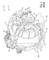
- FIG. 8 is a fragmentary front perspective view of a machine constructed in accordance with a first preferred embodiment of the present invention.
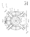
- FIG. 9 is a front view of the machine of FIG. 8 ;
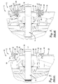
- FIG. 10 is a side sectional view of the machine of FIGS. 8 and 9 ;
- FIG. 11 is an exploded perspective view of the machine of FIGS. 8-10 ;
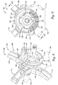
- FIG. 12 is is a front perspective view of the mounting ring of the machine of FIGS. 8-11 ;
- FIG. 13 is a rear perspective view of the mounting ring of FIG. 12 ;
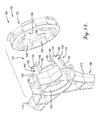
- FIG. 14 is an exploded perspective view of the frame and mounting ring of the machine of FIGS. 8-11 ;
- FIG. 15 is a fragmentary front perspective view of a machine constructed in accordance with a first preferred embodiment of the present invention.
- FIG. 16 is a front view of the machine of FIG. 15 ;
- FIG. 17 is a side sectional view of the machine of FIGS. 15 and 16 ;
- FIG. 18 is an exploded perspective view of the machine of FIGS. 15-17 ;
- FIG. 19 is an exploded rear perspective view of the frame and mounting ring of the machine of FIGS. 15-18 , prior to axial movement of the ring onto the frame for assembly;
- FIG. 20 is a rear perspective view of the frame and mounting ring of FIG. 19 , after axial movement of the ring onto the frame and prior to twisting of the ring about the frame for assembly;
- FIG. 21 is a front perspective view of the frame and mounting ring as shown in FIG. 20 , after axial movement of the ring onto the frame and prior to twisting of the ring about the frame for assembly;
- FIG. 22 is a rear perspective view of the frame and mounting ring of FIGS. 19-21 , after twisting of the ring about the frame for assembly.
- a prior art machine 10 including a motor 12 is depicted.
- the machine 10 may suitably be any one of a variety of types, including but not limited to clothes dryers, washing machines, etc. It is noted that the motor is particularly suitable for use in a horizontal orientation, with the rotor axis being at least generally horizontal, although such an arrangement is not required.
- the motor 12 includes a rotor 14 that is rotatable about an axis and a stator 16 positioned radially outside the rotor 14.
- a motor frame 18 supports the stator 16, and the motor 12 as a whole is supported in the machine 10 on a motor support 20.
- the axial halves of the motor 12 are configured in a substantially symmetrical manner.
- the frame 18 includes at least substantially identical portions 18a,18b
- the support 20 includes at least substantially identical portions 20a,20b. Therefore, for the sake of convenience and clarity, further discussion of the machine 10 and the motor 12 will refer only to one axial portion of the motor 12 (e.g, to the components associated with a single frame portion 18a or 18b). It should be understood, however, that it is permissible for one or more additional components similar to or identical to those described below to be present in the motor 12 or the machine 10 as a whole.
- the motor 12 is supported in the machine 10 by an annular mounting ring 22 that rests on the motor support 20.
- a strap 24 is provided to prevent movement of the motor 12 away from the support 20 due to vibration or other jarring of the machine 10.
- the mounting ring 22 is secured on the motor 12 by a mounting cap 26.
- the mounting cap 26 includes a radially extending plate 28, a circumferential sidewall 30 extending axially from the plate 28, and an annular lip 32 extending radially from the sidewall 30.
- the motor frame 18 defines a cap-receiving opening 34.
- the plate 28 is sized such that the associated sidewall 30 frictionally engages the frame 18 when the cap 26 is inserted along a first axial direction into the cap-receiving opening 34. That is, the cap 26 and the frame 18 are connected via a press fit.
- the lip 32 limits axial movement of the cap 26 into the cap-receiving opening 34 in the first direction and also at least substantially blocks movement of the mounting ring 22 away from the frame 18 in a second direction, wherein the second direction is opposite of the first direction.
- axial movement of the mounting ring 22 toward the frame 18 (in the first direction) is limited by a plurality of circumferentially spaced shoulders 36 that are part of the frame 18.
- the mounting cap 26 includes a resiliently deformable portion 38 that is circumscribed by a rigid portion 40.
- the deformable portion 38 includes a plurality of circumferentially spaced nodules 42. As shown in FIG. 4 , the nodules 42 are configured to be compressed by the mounting cap 26 as necessary and function as a tolerancing mechanism to ensure a good fit of the deformable portion 38 between the lip 32 and the shoulders 36.
- the machine 100 includes a motor 102.
- the motor 102 includes a rotor 104 having a rotor shaft 106 that is rotatable about an axis.
- the rotor shaft 106 is particularly suited to support a belt sheave (not shown), although such an arrangement is not required.
- the motor 102 also includes a stator (not shown) preferably positioned radially outside the rotor 104.
- the motor prefferably be of an outer rotor type, with the rotor positioned radially outside of the stator, or to be a dual rotor motor having a first rotor positioned radially inside of the stator and a second rotor positioned radially outside of the stator. Any of a variety of other motor configurations are permissible, as well.
- the machine 100 of the first preferred embodiment may suitably be any one of a variety of types, including but not limited to clothes dryers.
- the machine 100 of the first preferred embodiment preferably includes substantially similar halves or portions and will be both discussed and illustrated with reference to only one of such halves. It should be understood, however, that it is permissible for one or more additional components similar to or identical to those described below to be present in the machine 100 of the first preferred embodiment.
- the motor 102 preferably includes a motor frame 108 including a bearing hub 110 and a plurality of arcuately spaced apart, generally radially extending arms 112 that extend from the bearing hub 110 and support the stator.
- the bearing hub 110 preferably supports a bearing 114 ( FIG. 10 ) that rotatably supports the rotor shaft 106. Any one or more of a variety of bearing types, including ball bearings, are suitable for use with the present invention.
- the bearing hub 110 includes wall structure 116 that presents a bearing-engaging surface 118 spaced radially inwardly from a ring-engaging surface 120.
- the ring-engaging surface 120 will be discussed in greater detail below.
- the motor 102 preferably includes a mounting ring 122.
- the mounting ring 122 is preferably circular and annular in form, although it is within the scope of some aspects of the present invention for the ring to take any of a variety of forms.
- the mounting ring could be a disc lacking an opening therethrough, or the mounting ring could be annular but have varying inner and outer perimeter shapes.
- the outer perimeter might be rectangular, for instance, while the inner perimeter might be circular.
- the mounting ring 122 preferably includes a resiliently deformable portion 124 and a rigid portion 126 that at least substantially circumscribes the deformable portion 124.
- the deformable portion 124 comprises rubber
- the rigid portion 126 comprises a hard plastic that is preferably overmolded over the rubber deformable portion 124.
- any one or more of a variety of materials may be used without departing from the scope of the present invention. It is also permissible within the scope of some aspects of the present invention for the mounting ring to include a single rigid or deformable portion or to include more portions than the two preferred portions described above. Even further, it is within the scope of some aspects of the present invention for the deformable portion to circumscribe the rigid portion.
- the mounting ring 122 preferably circumscribes the corresponding ring-engaging surface 120 of the wall structure 116 such that the deformable portion 124 contacts the ring-engaging surface 120 and is preferably resiliently compressed between the rigid portion 126 and the ring-engaging surface 120. This arrangement will be discussed in greater detail below.
- the deformable portion 124 circumscribes the rigid portion 126
- the rotor shaft 106 preferably passes through the center of each mounting ring 122 and is rotatable relative thereto while supported on the bearing 114. It is permissible, however, for an alternative shaft arrangement to be used. For instance, the shaft might be oriented in such a manner that the mounting ring center does not lie on the axis of the shaft (e.g., the shaft might be oriented perpendicularly to the mounting ring central axis), or the shaft might include an offset section that passes outside the mounting ring.
- the center of the mounting ring prefferably be positioned in axial alignment with the center of the bearing or to be offset. It is also permissible for the mounting ring to be positioned radially outside, radially inside, or in part radially inside and in part radially outside the bearing. In some configurations, the mounting ring might be positioned orthogonally to the bearing or at some other angle to the bearing. Furthermore, the mounting ring and bearing should not be limited to longitudinal alignment. That is, the mounting ring may be shifted in an axial direction relative to the bearing.
- a shield 128 is attached to the rotor shaft 106 and provides a physical barrier against encroachment of dust or other debris into the motor 102.
- any suitable dust or debris barrier may be applied without departing from the scope of the present invention, or such a barrier may be excluded entirely.
- the machine 100 preferably includes a motor support 130 with a ring-receiving opening 132 ( FIG. 11 ).
- the mounting ring 122 is secured in the ring-receiving opening 132 and supports the motor 102 in the machine 100.
- the motor support 130 includes strap-receiving projections 134.
- a strap 136 is attached to the support 130 at the strap-receiving projections 134 and extends around a portion of the mounting ring 122 to further secure the mounting ring 122 and motor 102 in the machine 100. More particularly, as best shown in FIGS.
- the rigid portion 126 of the mounting ring 122 preferably includes a plurality of circumferentially spaced apart, axially staggered strap guides 138 defining a pathway 140 therebetween.
- the strap 136 extends from a first of the strap-receiving projections 134 and along the pathway 140 to a second of the strap-receiving projections 134.
- the wall structure 116 includes a catch 142 comprising a plurality of circumferentially spaced apart, radially extending catch projections 144. It is permissible, however, for a single catch projection to be provided and to extend arcuately about only a portion of the wall structure or to completely circumscribe the wall structure.
- each of the catch projections 144 defines a flat surface 146 spaced axially from a sloped surface 148.
- the wall structure 116 also preferably includes a plurality of first radially extending faces 150 and second radially extending faces 152 arcuately spaced from the corresponding first faces 150.
- the corresponding first and second faces 150,152 preferably define a groove 154 therebetween.
- the catch projections 144 extend between corresponding faces 150,152 so as to span the corresponding groove 154. It is permissible, however, for the catch projections 144 to span only partway across the groove 154 or to extend beyond one or both of the faces 150,152.
- the deformable portion 124 of the mounting ring 122 preferably includes a plurality of ribs 156 corresponding to the grooves 154.
- the ribs 156 are preferably separated by arcuately extending spaces.
- the deformable portion 124 also preferably includes locking surfaces 160 (best shown in FIGS. 9 , 11 , and 12 ) corresponding to the catch projections 144. Although multiple discrete locking surfaces are preferred, a single locking surface may be provided without departing from the scope of the present invention and would most suitably correspond to an alternative embodiment utilizing a single catch projection.
- the mounting ring 122 For assembly of the mounting ring 122 onto the frame 108, the mounting ring 122 is initially positioned as shown in FIGS. 11 and 14 , with the ribs 156 of the mounting ring 122 arcuately aligned with corresponding grooves 154. The mounting ring 122 is then moved in a first axial direction toward the frame 108. The ribs 156 of the deformable portion 124 of the mounting ring 122 then engage the sloped surfaces 148 of the catch projections 144 and are resiliently compressed by the catch projections 144 upon continued application of a force in the first axial direction.
- the deformation is eventually such that the deformable portion 124 and, in turn, the mounting ring 122 as a whole passes by the sloped surfaces 148 and catch projections 144.
- the ribs 156 are then received in the grooves 154, as shown in FIGS. 8-10 .
- each of the first faces 150 includes a radially extending shoulder 162 ( FIGS. 11 and 14 ).
- the shoulders 162 block further axial movement of the mounting ring 122 in the first direction.
- Axial movement of the mounting ring 122 relative to the frame 108 in a second axial direction opposite the first axial direction is blocked by engagement of the locking surfaces 160 by the catch projections 144. Twisting of the mounting ring 122 relative to the frame 108 is blocked by engagement of the first and second faces 150,152 with the corresponding ribs 156.
- the deformable portion 124 of the mounting ring 122 is radially compressed between the rigid portion 126 and the ring-engaging surface 120 such that twisting is also inhibited by friction.
- rib-and-groove configuration described above is particularly useful for preventing or restricting relative rotation between the mounting ring and the frame.
- alternative configurations may be used to similar effect without departing from the scope of the present invention.
- complementary holes and posts could be provided on respective ones of the mounting ring and the frame.
- the mounting ring 122 is secured on the frame 108 through means of wall structure 116 that is integrally formed with the frame 108. It is permissible within the scope of some aspects of the present invention, however, for various modifications to the preferred embodiment described above to be implemented. For instance, components of the wall structure or even the wall structure in its entirety might be non-integral with the frame. The shoulders could be formed on the second faces or entirely independently from the faces, or alternate structure to prevent axial motion in the first axial direction might be provided. As briefly noted above, the mounting components in general could be largely inverted to accommodate a mounting ring having a radially outer deformable portion and a radially inner rigid portion. Furthermore, it is permissible for the locking surfaces to be defined by both the deformable portion and the rigid portion or to be defined by the rigid portion alone.
- the structure described above enables numerous advantages. For instance, provision of wall structure 116 that engages the mounting ring 122 enables the mounting ring 122 to be secured on the motor frame 108 without use of an additional component such as amounting cap, thus reducing both the total cost of the motor 102 and the time required for mounting of the motor 102 in the machine 100.
- FIGS. 15-22 a second preferred embodiment of the present invention is illustrated. It is initially noted that, with certain exceptions to be discussed in detail below, many of the elements of the machine 200 of the second embodiment are the same as or very similar to those described in detail above in relation to the machine 100 of the first embodiment. Therefore, for the sake of brevity and clarity, redundant descriptions and numbering will be generally avoided here. Unless otherwise specified, the detailed descriptions of the elements presented above with respect to the first embodiment should therefore be understood to apply to the second embodiment, as well.
- the machine 200 of the second preferred embodiment includes a motor 202 including a frame 204 that presents a bearing hub 206.
- the frame 204 (and, more preferably, the bearing hub 206 of the frame 204) preferably includes wall structure 208 that defines a ring-engaging surface 210.
- the wall structure 208 also includes a catch 212 preferably comprising a plurality of circumferentially spaced apart, radially extending proximal catch projections 214 and a plurality circumferentially spaced apart, radially extending distal catch projections 216 spaced axially from the proximal catch projections 214.
- the wall structure 208 defines a plurality of rib-receiving slots 218, each of which is arcuately adjacent a corresponding groove 220. More particularly, a plurality of radially extending faces 22 extend from the ring-engaging surface 210 and each define one arcuate side of a corresponding groove 220. The other arcuate side of each groove 220 is open so as to be in communication with a corresponding one of the rib-receiving slots 218. Preferably, the grooves 220 are shallow in comparison to the rib-receiving slots 218. As shown in FIGS.
- each groove 220 is defined by a platform 224 that projects radially outwardly relative to a surface 226 that defines the radially innermost boundary of each rib-receiving slot 218.
- one of the distal catch projections 214 extends radially outwardly and in a first arcuate direction from each of the faces 222 so as to extend at least partially across the corresponding groove 220.
- one of the proximal catch projections 216 preferably extends radially outwardly from each of the faces 22 in a second arcuate direction opposite the first arcuate direction, so as to extend at least partially across the adjacent rib-receiving slot 218.
- the motor 202 preferably includes a mounting ring 228 including a deformable portion 230 and arigid portion 232 that preferably circumscribes the deformable portion 230.
- the deformable portion 230 preferably includes a plurality of ribs 232 corresponding to the grooves 220.
- the ribs 232 are preferably separated by arcuately extending spaces 236.
- the deformable portion 230 also preferably includes locking surfaces 238 (best shown in FIGS. 16 , 18 , and 21 ) corresponding to the distal catch projections 214.
- the mounting ring 228 For assembly of the mounting ring 228 onto the frame 204, the mounting ring 228 is initially positioned as shown in FIGS. 18 and 19 , with the ribs 232 of the mounting ring 228 arcuately aligned with corresponding rib-receiving slots 218. The mounting ring 228 is then moved in a first axial direction toward the frame 204 such that the ribs 232 of the mounting ring 228 are inserted into corresponding rib-receiving slots 218.
- the spaces 236 between the ribs 234 are preferably expansive enough to allow to the mounting ring 228 to pass unobstructed over the corresponding face 222 and platform 224 during the axial movement. As shown in FIG.
- the deformable portion 230 then comes into contact with the proximal catch projections 214, which block further axial movement of the mounting ring 228 in the first direction.
- the locking surfaces 238 and the distal catch projections 214 are alternately arcuately arranged after the completion of the axial motion in the first direction.
- each rib 234 is received in the corresponding groove 220 and is preferably radially compressed between the rigid portion 232 of the mounting ring 228 and the corresponding platform 224 of the wall structure 208.
- Such compression serves to restrict untwisting of the mounting ring 228 relative to the frame 204.
- a plurality of arcuately spaced apart, axially extending stops might be provided for engagement with the edges of the ribs adjacent the respective open arcuate side of each groove.
- These stops could include a sloped surface to allow traverse via twisting in one direction and a flat, radially extending surface to prevent traverse via twisting in the other direction.
- the stops could be separate from or integral with the frame.
- the stops could be immovable or be configured to be put into position (e.g., by pivoting, snapping into place, or arcuate or radial sliding or translation) only after the mounting ring has been twisted into place.
- Stopping means could be provided on or be inherent to other parts of the machine, motor, or frame as well. For instance, openings provided in the arcuately spaced apart arms could be utilized. Ultimately, it is within the scope of the present invention for any of a variety of physical stop mechanisms, including mechanisms not described above, to be used to prevent untwisting of the mounting ring from the frame.
- Axial movement of the mounting ring 228 relative to the frame 204 in a second axial direction opposite the first axial direction is blocked by engagement of the locking surfaces 238 by the distal catch projections 214. Further twisting of the mounting ring 228 relative to the frame 204 in the indicated direction is blocked by engagement of the faces 222 with the corresponding ribs 234.
- the direction of twist for securing the mounting ring 228 onto the frame 204 will be dependent on the direction of the torques that will be applied by the motor 202 during operation of the machine 200. Furthermore, with reference to a motor having a similar or identical mounting ring at each of its axial end, it is understood that the twist directions may preferably be opposite one another.
- rib-and-groove configuration described above is particularly useful for preventing or restricting relative rotation between the mounting ring and the frame.
- alternative configurations may be used to similar effect without departing from the scope of the present invention.
- complementary holes and posts could be provided on respective ones of the mounting ring and the frame.
- the mounting ring 228 is secured on the frame 204 through means of wall structure 208 that is integrally formed with the frame 204. It is permissible within the scope of some aspects of the present invention, however, for various modification to the preferred embodiment described above to be implemented. For instance, components of the wall structure or even the wall structure in its entirety might be non-integral with the frame. As briefly noted above, the mounting components in general could be largely inverted to accommodate a mounting ring having a radially outer deformable portion and a radially inner rigid portion. Furthermore, it is permissible for the locking surfaces to be defined by both the deformable portion and the rigid portion or to be defined by the rigid portion alone.
- the structure described above enables numerous advantages. For instance, provision of wall structure 208 that engages the mounting ring 228 enables the mounting ring 228 to be secured on the motor frame 204 without use of an additional component such as amounting cap, thus reducing both the total cost of the motor 202 and the time required for mounting of the motor 202 in the machine 200.
Landscapes
- Engineering & Computer Science (AREA)
- Power Engineering (AREA)
- Textile Engineering (AREA)
- Motor Or Generator Frames (AREA)
- Connection Of Motors, Electrical Generators, Mechanical Devices, And The Like (AREA)
Applications Claiming Priority (1)
| Application Number | Priority Date | Filing Date | Title |
|---|---|---|---|
| US13/626,652 US8890384B2 (en) | 2012-09-25 | 2012-09-25 | Capless mounting for motor |
Publications (1)
| Publication Number | Publication Date |
|---|---|
| EP2712064A2 true EP2712064A2 (fr) | 2014-03-26 |
Family
ID=49237012
Family Applications (1)
| Application Number | Title | Priority Date | Filing Date |
|---|---|---|---|
| EP13184633.9A Withdrawn EP2712064A2 (fr) | 2012-09-25 | 2013-09-16 | Moteur électrique ayant un support annulaire |
Country Status (4)
| Country | Link |
|---|---|
| US (1) | US8890384B2 (fr) |
| EP (1) | EP2712064A2 (fr) |
| KR (1) | KR20140043277A (fr) |
| CN (2) | CN203554166U (fr) |
Cited By (1)
| Publication number | Priority date | Publication date | Assignee | Title |
|---|---|---|---|---|
| EP4012094A1 (fr) * | 2020-12-11 | 2022-06-15 | Whirlpool Corporation | Isolateur de vibrations pour un moteur d'appareil ayant des vides silencieux internes |
Families Citing this family (9)
| Publication number | Priority date | Publication date | Assignee | Title |
|---|---|---|---|---|
| US8890384B2 (en) * | 2012-09-25 | 2014-11-18 | Nidec Motor Corporation | Capless mounting for motor |
| WO2016100741A2 (fr) | 2014-12-19 | 2016-06-23 | Aerovironment, Inc. | Support de moteur et amortisseur |
| CN105391221A (zh) * | 2015-12-24 | 2016-03-09 | 泰信电机(苏州)有限公司 | 一种烘干机电机用外壳组件 |
| CN105391222A (zh) * | 2015-12-24 | 2016-03-09 | 泰信电机(苏州)有限公司 | 一种烘干机电机用外壳 |
| CN105391232A (zh) * | 2015-12-24 | 2016-03-09 | 泰信电机(苏州)有限公司 | 一种烘干机电机用垫圈 |
| CN107248795A (zh) * | 2017-08-14 | 2017-10-13 | 珠海格力节能环保制冷技术研究中心有限公司 | 电机、电机组件和电器设备 |
| CN110318218A (zh) * | 2018-03-30 | 2019-10-11 | 青岛海尔滚筒洗衣机有限公司 | 衣物处理设备 |
| CN110323876A (zh) * | 2018-03-30 | 2019-10-11 | 青岛海尔滚筒洗衣机有限公司 | 用于衣物处理设备的直驱电机和衣物处理设备 |
| WO2025138104A1 (fr) * | 2023-12-29 | 2025-07-03 | 舍弗勒技术股份两合公司 | Ensemble bague et son procédé d'assemblage, et groupe motopropulseur de véhicule |
Family Cites Families (16)
| Publication number | Priority date | Publication date | Assignee | Title |
|---|---|---|---|---|
| US4186319A (en) * | 1977-04-26 | 1980-01-29 | General Electric Company | Dynamoelectric machine end shield |
| US6462446B2 (en) * | 1999-12-27 | 2002-10-08 | General Electric Company | Resilient ring motor mounting assembly |
| CA2329680A1 (fr) * | 1999-12-30 | 2001-06-30 | Michael A. Cook | Rondelle a trois couches |
| US6809445B2 (en) * | 2002-04-04 | 2004-10-26 | General Electric Company | Method and apparatus for electric motor lead wire retention |
| DE10305649A1 (de) * | 2003-02-12 | 2004-08-26 | Robert Bosch Gmbh | Außenläufermotor |
| DE10344624A1 (de) * | 2003-09-25 | 2005-04-28 | Bosch Gmbh Robert | Schwingungsdämpfende Aufnahme |
| US20070188026A1 (en) * | 2006-01-31 | 2007-08-16 | Zhongshan Broad-Ocean Motor Co., Ltd. | Damping structure for a rotor assembly of a motor |
| US20070177978A1 (en) * | 2006-01-31 | 2007-08-02 | Zhongshan Broad-Ocean Motor Co., Ltd. | Damping structure for a rotor assembly of a motor |
| CN201450438U (zh) * | 2009-07-31 | 2010-05-05 | 中山大洋电机股份有限公司 | 一种电机 |
| US8278793B2 (en) * | 2009-11-13 | 2012-10-02 | Nidec Motor Corporation | Motor endshield |
| CN201623575U (zh) * | 2010-03-01 | 2010-11-03 | 中山大洋电机制造有限公司 | 一种电机减震圈安装系统 |
| CN201674314U (zh) * | 2010-01-29 | 2010-12-15 | 中山大洋电机制造有限公司 | 一种电机连接支架结构 |
| CN201674325U (zh) * | 2010-04-30 | 2010-12-15 | 中山大洋电机制造有限公司 | 一种电机用减震圈及其应用的电机 |
| CN103006104A (zh) * | 2011-09-26 | 2013-04-03 | 德昌电机(深圳)有限公司 | 食物处理机、电机组件及面包机 |
| CN202353372U (zh) * | 2011-12-03 | 2012-07-25 | 中山大洋电机股份有限公司 | 一种新型减震圈及其应用的电机 |
| US8890384B2 (en) * | 2012-09-25 | 2014-11-18 | Nidec Motor Corporation | Capless mounting for motor |
-
2012
- 2012-09-25 US US13/626,652 patent/US8890384B2/en active Active
-
2013
- 2013-09-16 EP EP13184633.9A patent/EP2712064A2/fr not_active Withdrawn
- 2013-09-24 KR KR1020130113234A patent/KR20140043277A/ko not_active Abandoned
- 2013-09-25 CN CN201320603304.8U patent/CN203554166U/zh not_active Expired - Fee Related
- 2013-09-25 CN CN201310445409.XA patent/CN103683636A/zh active Pending
Non-Patent Citations (1)
| Title |
|---|
| None |
Cited By (2)
| Publication number | Priority date | Publication date | Assignee | Title |
|---|---|---|---|---|
| EP4012094A1 (fr) * | 2020-12-11 | 2022-06-15 | Whirlpool Corporation | Isolateur de vibrations pour un moteur d'appareil ayant des vides silencieux internes |
| US11781616B2 (en) | 2020-12-11 | 2023-10-10 | Whirlpool Corporation | Vibration isolator for an appliance motor having internal silencing voids |
Also Published As
| Publication number | Publication date |
|---|---|
| US20140084726A1 (en) | 2014-03-27 |
| CN103683636A (zh) | 2014-03-26 |
| CN203554166U (zh) | 2014-04-16 |
| US8890384B2 (en) | 2014-11-18 |
| KR20140043277A (ko) | 2014-04-09 |
Similar Documents
| Publication | Publication Date | Title |
|---|---|---|
| US8890384B2 (en) | Capless mounting for motor | |
| US11641138B2 (en) | Multi-component rotor for an electric motor of an appliance | |
| AU2014100770A4 (en) | Detachable blades for a ceiling fan | |
| CN208233359U (zh) | 动力套装 | |
| WO2006078114A3 (fr) | Moteur de type a double rotor | |
| US9062759B2 (en) | Pulley device with a damping element | |
| CN101925476B (zh) | 配有止动装置的家具辊子用的转轮 | |
| CN103374770B (zh) | 自由端纺纱转子 | |
| US20060137958A1 (en) | Conveyor idler with locking device for preventing reverse rotation | |
| KR102164515B1 (ko) | 건조기의 동력 전달용 풀리 조립체 | |
| CN204939934U (zh) | 一种滚筒支撑装置及具有其的干衣机 | |
| KR200402886Y1 (ko) | 세탁기용 배수펌프 | |
| CN105088714B (zh) | 一种滚筒支撑装置及具有其的干衣机 | |
| AU2014201693A1 (en) | Separator, separating device with such a separator, and vacuum cleaner, especially wet vacuum cleaner, with such a separator or such a separating device | |
| KR102089743B1 (ko) | 전동압축기의 모터 회전자 | |
| KR20110108758A (ko) | 모터 직결형 구동휠 유닛 및 이를 구비한 이동 로봇 | |
| AU2018323321B2 (en) | Mop | |
| EP1096184A2 (fr) | Joint d'étanchéité entre deux éléments en rotation, par exemple un axe et et un moyeu | |
| CN218498928U (zh) | 电机总成以及电气产品 | |
| CN219461039U (zh) | 一种具有支撑胶件的滚刷 | |
| JPS5927539Y2 (ja) | ころがり軸受の割型保持器 | |
| TWM668211U (zh) | 推脂機結構 | |
| CN108916255B (zh) | 用于电机的花键套、转子组件、电机以及家用电器 | |
| JP2003004121A (ja) | プーリユニット | |
| FI77521B (fi) | Stoedhjulsenhet foer en hushaollsmaskin, saerskilt en tvaettmaskin. |
Legal Events
| Date | Code | Title | Description |
|---|---|---|---|
| PUAI | Public reference made under article 153(3) epc to a published international application that has entered the european phase |
Free format text: ORIGINAL CODE: 0009012 |
|
| AK | Designated contracting states |
Kind code of ref document: A2 Designated state(s): AL AT BE BG CH CY CZ DE DK EE ES FI FR GB GR HR HU IE IS IT LI LT LU LV MC MK MT NL NO PL PT RO RS SE SI SK SM TR |
|
| AX | Request for extension of the european patent |
Extension state: BA ME |
|
| STAA | Information on the status of an ep patent application or granted ep patent |
Free format text: STATUS: THE APPLICATION IS DEEMED TO BE WITHDRAWN |
|
| 18D | Application deemed to be withdrawn |
Effective date: 20160401 |