EP2712153A2 - Drahtlose breitbandige vorrichtung - Google Patents
Drahtlose breitbandige vorrichtung Download PDFInfo
- Publication number
- EP2712153A2 EP2712153A2 EP11777288.9A EP11777288A EP2712153A2 EP 2712153 A2 EP2712153 A2 EP 2712153A2 EP 11777288 A EP11777288 A EP 11777288A EP 2712153 A2 EP2712153 A2 EP 2712153A2
- Authority
- EP
- European Patent Office
- Prior art keywords
- main body
- battery
- end cover
- wireless broadband
- circuit
- Prior art date
- Legal status (The legal status is an assumption and is not a legal conclusion. Google has not performed a legal analysis and makes no representation as to the accuracy of the status listed.)
- Withdrawn
Links
Images


Classifications
-
- H—ELECTRICITY
- H04—ELECTRIC COMMUNICATION TECHNIQUE
- H04W—WIRELESS COMMUNICATION NETWORKS
- H04W52/00—Power management, e.g. Transmission Power Control [TPC] or power classes
- H04W52/02—Power saving arrangements
- H04W52/0209—Power saving arrangements in terminal devices
- H04W52/0261—Power saving arrangements in terminal devices managing power supply demand, e.g. depending on battery level
- H04W52/0296—Power saving arrangements in terminal devices managing power supply demand, e.g. depending on battery level switching to a backup power supply
-
- H—ELECTRICITY
- H04—ELECTRIC COMMUNICATION TECHNIQUE
- H04M—TELEPHONIC COMMUNICATION
- H04M1/00—Substation equipment, e.g. for use by subscribers
- H04M1/02—Constructional features of telephone sets
- H04M1/0202—Portable telephone sets, e.g. cordless phones, mobile phones or bar type handsets
- H04M1/0249—Details of the mechanical connection between the housing parts or relating to the method of assembly
- H04M1/0252—Details of the mechanical connection between the housing parts or relating to the method of assembly by means of a snap-on mechanism
-
- H—ELECTRICITY
- H04—ELECTRIC COMMUNICATION TECHNIQUE
- H04M—TELEPHONIC COMMUNICATION
- H04M1/00—Substation equipment, e.g. for use by subscribers
- H04M1/02—Constructional features of telephone sets
- H04M1/0202—Portable telephone sets, e.g. cordless phones, mobile phones or bar type handsets
- H04M1/026—Details of the structure or mounting of specific components
- H04M1/0262—Details of the structure or mounting of specific components for a battery compartment
-
- H—ELECTRICITY
- H04—ELECTRIC COMMUNICATION TECHNIQUE
- H04M—TELEPHONIC COMMUNICATION
- H04M1/00—Substation equipment, e.g. for use by subscribers
- H04M1/72—Mobile telephones; Cordless telephones, i.e. devices for establishing wireless links to base stations without route selection
- H04M1/724—User interfaces specially adapted for cordless or mobile telephones
- H04M1/72448—User interfaces specially adapted for cordless or mobile telephones with means for adapting the functionality of the device according to specific conditions
- H04M1/7246—User interfaces specially adapted for cordless or mobile telephones with means for adapting the functionality of the device according to specific conditions by connection of exchangeable housing parts
-
- Y—GENERAL TAGGING OF NEW TECHNOLOGICAL DEVELOPMENTS; GENERAL TAGGING OF CROSS-SECTIONAL TECHNOLOGIES SPANNING OVER SEVERAL SECTIONS OF THE IPC; TECHNICAL SUBJECTS COVERED BY FORMER USPC CROSS-REFERENCE ART COLLECTIONS [XRACs] AND DIGESTS
- Y02—TECHNOLOGIES OR APPLICATIONS FOR MITIGATION OR ADAPTATION AGAINST CLIMATE CHANGE
- Y02D—CLIMATE CHANGE MITIGATION TECHNOLOGIES IN INFORMATION AND COMMUNICATION TECHNOLOGIES [ICT], I.E. INFORMATION AND COMMUNICATION TECHNOLOGIES AIMING AT THE REDUCTION OF THEIR OWN ENERGY USE
- Y02D30/00—Reducing energy consumption in communication networks
- Y02D30/70—Reducing energy consumption in communication networks in wireless communication networks
Definitions
- the present invention relates to the field of communications technologies, and in particular to a wireless broadband device.
- a wireless broadband device is also called a mobile broadband device, and is currently an Internet access medium widely applied on a communications network.
- a terminal such as a mobile phone and a computer
- Common wireless broadband devices mainly include three types, namely, a Wideband Code Division Multiple Access (Wideband Code Division Multiple Access, WCDMA) mobile broadband device, a Code Division Multiple Access 2000 (Code Division Multiple Access 2000) mobile broadband device, and a Time Division-Synchronous Code Division Multiple Access (Time Division-Synchronous Code Division Multiple Access, TD-SCDMA) mobile broadband device.
- WCDMA Wideband Code Division Multiple Access
- CDMA Code Division Multiple Access 2000
- TD-SCDMA Time Division-Synchronous Code Division Multiple Access
- An existing wireless broadband device carries one battery to supply power to a circuit, so as to enable the wireless broadband device to implement a wireless broadband function.
- the power supply capacity of one battery is very low, resulting in a short working duration of the mobile broadband device.
- a user needs to charge a battery or replace a battery frequently, causing poor user experience.
- Embodiments of the present invention provide a wireless broadband device, where the wireless broadband device has a long power supply duration, which brings good user experience.
- a wireless broadband device includes:
- a first battery is carried in a main body included in a wireless broadband device and serves as a main battery to supply power to a circuit of the main body, so as to enable the main body to implement a wireless broadband function;
- a second battery is built in an end cover and a power output contact of the second battery emerges from an inner side of the end cover.
- the wireless broadband device provided in the embodiment of the present invention supplies power to the circuit of the main body by using the first battery carried in the main body and the second battery built in the end cover.
- the wireless broadband device provided in the embodiment of the present invention has a longer power supply duration, and the wireless broadband device is easily portable, which brings good user experience.
- a wireless broadband device provided in the embodiment of the present invention may include:
- the main body 1 when the main body 1 is separated from the end cover 2, the main body 1 may also be separately used, thereby implementing a wireless broadband function.
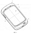
- the main body 1 may also be disposed with a removable battery cover 11, as shown in FIG. 3 , where the battery cover 11 is configured to cover the first battery carried in the main body 1, thereby protecting the first battery.
- the battery cover 11 is removable, and therefore the first battery in the battery cover 11 may be conveniently replaced. In another embodiment of the present invention, when the main body 1 and the end cover 2 are assembled, it does not need to remove the battery cover 11.
- the main body 1 and the end cover 2 may be assembled to form a whole in a manner of a snap joint, as shown in FIG. 1 , FIG. 3 , and FIG. 4 , where a snap pin 22 disposed on the end cover 2 and a snap joint 13 disposed on the main body 1 may match each other, so that the main body 1 and the end cover 2 are assembled to form a whole.
- the main body 1 and the end cover 2 may also be assembled to form a whole in a manner of magnet attraction.
- one or more magnets may be embedded in a surface of the main body 1 that contacts the end cover 2, and one or more magnets may also be embedded in the inner side of the end cover 2.
- the magnets embedded in the surface of the main body 1 and the magnets embedded in the inner side of the end cover 2 may be equal in quantity, correspond vertically in position, and be opposite in polarity, so that the main body 1 and the end cover 2 may be assembled to form a whole in a manner of magnet attraction.
- a layout of the magnets embedded in the surface of the main body 1 that contacts the end cover 2 may match the layout of the magnets embedded in the inner side of the end cover 2, so that the main body 1 and the end cover 2 may be assembled to form a whole in a manner of magnet attraction in a direction of installation, while in an opposite direction of installation, the main body 1 and the end cover 2 cannot be assembled to form a whole because of repulsion between like poles of magnets, thereby achieving an effect of preventing installation in an opposite direction.
- the main body 1 and the end cover 2 may also be assembled to form a whole in a manner of a guide rail; or, the main body 1 and the end cover 2 are assembled to form a whole in a manner of rotation, to which it is not limited by the embodiment of the present invention.
- the end cover 2 and the second battery may be an integral structure, similar to a battery cover with a cell for a mobile phone.
- the end cover 2 and the second battery may also be a removable structure, that is, the second battery is built in the end cover 2, and is covered by the inner side of the end cover 2.
- a power switch 14 is disposed on a side of the main body 1 and is configured to turn on or off the power supply to the circuit of the main body 1.
- a power supply voltage range of the circuit of the main body 1 is generally 3.4 V to 4.2 V.
- the circuit of the main body 1 may switch to the second battery for power supply, so that a power supply duration of the wireless broadband device may be increased, and the number of recharging times and a frequency of battery replacement by a user are decreased.
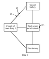
- a dual power switch circuit 15 may be disposed in the main body 1, where the dual power switch circuit 15 electrically connects to the circuit of the main body 1, the first battery, and the second battery, respectively.
- FIG. 4 is a schematic diagram of the dual power switch circuit 15 electrically connecting to the circuit of the main body 1, the first battery, and the second battery, respectively.
- the dual power switch circuit 15 may switch the circuit of the main body 1 to the second battery for power supply.
- the dual power switch circuit 15 disconnects a circuit loop formed by the dual power switch circuit 15, the first battery, and the circuit of the main body 1, and instead connects a circuit loop formed by the dual power switch circuit 15, the second battery, and the circuit of the main body 1, so as to switch the circuit of the main body 1 to the second battery for power supply.
- a power P-PET controller LTC4414 may be used to build a dual power switch circuit, so as to implement switching of power supply between the first battery and the second battery for the circuit of the main body 1, to which it is not limited by the embodiment of the present invention.
- a specific implementation process of using a power P-PET controller LTC4414 to build a dual power switch circuit is common knowledge of a person of skill in the art, and therefore is not described in detail in the embodiment of the present invention.
- another component may also be used to build a dual power switch circuit to implement the present invention, to which it is not limited by the embodiment of the present invention.
- the wireless broadband device may be a mobile WIFI hotspot device, may also be a WCDMA mobile broadband device, a CDMA2000 mobile broadband device, or a TD-SCDMA mobile broadband device, and may also be other high-end data cards, as long as these high-end data cards may connect to a network side through a radio link in an uplink direction and may connect to a communications terminal through a WIFI link in a downlink direction to enable the communications terminal to access a network.
- the mobile broadband device includes, but is not limited to, a wireless Internet terminal.
- a first battery is carried in a main body included in a wireless broadband device and serves as a main battery to supply power to a circuit of the main body, so as to enable the main body to implement a wireless broadband function;
- a second battery is built in an end cover and a power output contact of the second battery emerges from an inner side of the end cover.
- the wireless broadband device provided in the embodiment of the present invention supplies power to the circuit of the main body by using the first battery carried in the main body and the second battery built in the end cover.
- the wireless broadband device provided in the embodiment of the present invention has a longer power supply duration, and the wireless broadband device is easily portable, which brings good user experience.
- the wireless broadband device provided in the embodiments of the present invention is described in detail in the foregoing.
- the principle and implementation manner of the present invention are described herein by using specific examples.
- the description about the embodiments of the present invention is merely provided for ease of understanding of the method and core ideas of the present invention.
- a person of ordinary skill in the art can make variations to the present invention in terms of specific implementation manner and application scope according to the ideas of the present invention. Therefore, the content of the specification shall not be construed as a limit to the present invention.
Landscapes
- Engineering & Computer Science (AREA)
- Signal Processing (AREA)
- Computer Networks & Wireless Communication (AREA)
- Mobile Radio Communication Systems (AREA)
- Transceivers (AREA)
- Telephone Set Structure (AREA)
- Charge And Discharge Circuits For Batteries Or The Like (AREA)
- Transmitters (AREA)
Applications Claiming Priority (1)
| Application Number | Priority Date | Filing Date | Title |
|---|---|---|---|
| PCT/CN2011/077426 WO2011137869A2 (zh) | 2011-07-21 | 2011-07-21 | 一种无线宽带设备 |
Publications (2)
| Publication Number | Publication Date |
|---|---|
| EP2712153A2 true EP2712153A2 (de) | 2014-03-26 |
| EP2712153A4 EP2712153A4 (de) | 2014-04-09 |
Family
ID=44904153
Family Applications (1)
| Application Number | Title | Priority Date | Filing Date |
|---|---|---|---|
| EP11777288.9A Withdrawn EP2712153A4 (de) | 2011-07-21 | 2011-07-21 | Drahtlose breitbandige vorrichtung |
Country Status (4)
| Country | Link |
|---|---|
| US (1) | US20140111961A1 (de) |
| EP (1) | EP2712153A4 (de) |
| CN (1) | CN102577336A (de) |
| WO (1) | WO2011137869A2 (de) |
Families Citing this family (6)
| Publication number | Priority date | Publication date | Assignee | Title |
|---|---|---|---|---|
| USD719939S1 (en) * | 2012-10-10 | 2014-12-23 | Huawei Device Co., Ltd. | Wireless router |
| US9002413B2 (en) * | 2012-10-25 | 2015-04-07 | Terrence Michael Furtney | Battery cell phone combination |
| USD771050S1 (en) * | 2015-09-21 | 2016-11-08 | JENETRIC GmbH | Fingerprint scanner with graphical display |
| CA3030766A1 (en) * | 2016-07-22 | 2018-01-25 | Mine Site Technologies Pty Ltd | Wireless communications unit |
| US20200036048A1 (en) * | 2018-07-26 | 2020-01-30 | Michael Donnell Adams, JR. | Dual battery system for cell phone |
| DE102019005358B4 (de) * | 2019-07-31 | 2023-06-07 | Dräger Safety AG & Co. KGaA | Mobiles Messgerät mit einem Energieversorgungsmodul und Verfahren zur Energieversorgung |
Family Cites Families (41)
| Publication number | Priority date | Publication date | Assignee | Title |
|---|---|---|---|---|
| DE1243766B (de) * | 1964-07-11 | 1967-07-06 | Varta Deutsche Edison Akkumula | Vorrichtung zur unterbrechungslosen Umschaltung eines Verbrauchers von Netz- auf Batteriebetrieb |
| US3577003A (en) * | 1969-03-11 | 1971-05-04 | Union Carbide Corp | Automatic battery-switching device |
| US4044268A (en) * | 1976-01-05 | 1977-08-23 | The Gates Rubber Company | Multiple power source automatic switching circuitry |
| JPS6071A (ja) * | 1983-06-15 | 1985-01-05 | Matsushita Electric Works Ltd | 電池による負荷駆動装置 |
| JP2594181B2 (ja) * | 1991-02-04 | 1997-03-26 | シャープ株式会社 | 携帯用電子機器 |
| US5523671A (en) * | 1991-02-14 | 1996-06-04 | Dell Usa, L.P. | Charging system for battery powered devices |
| US5272382A (en) * | 1991-06-24 | 1993-12-21 | Compaq Computer Corporation | Power supply for computer system manager |
| KR0138350B1 (ko) * | 1993-04-28 | 1998-06-15 | 김광호 | 지능화된 밧데리 전원 시스템 |
| JPH07307696A (ja) * | 1994-05-12 | 1995-11-21 | Oki Electric Ind Co Ltd | 携帯電子装置 |
| US5684384A (en) * | 1995-10-31 | 1997-11-04 | Motorola, Inc. | Apparatus and method for discharging and charging a multiple battery arrangement |
| US5717937A (en) * | 1996-03-04 | 1998-02-10 | Compaq Computer Corporation | Circuit for selecting and designating a master battery pack in a computer system |
| US5859481A (en) * | 1996-10-29 | 1999-01-12 | Ericsson Inc. | Auxiliary battery sensor switch |
| US6060789A (en) * | 1997-01-14 | 2000-05-09 | Citizen Watch Co., Ltd. | Power supply switching circuit for portable equipment |
| US6027828A (en) * | 1997-10-16 | 2000-02-22 | Advanced Mobile Solutions, Inc. | Modular stackable battery pack and accessories |
| GB2331666A (en) * | 1997-11-20 | 1999-05-26 | Dsc Telecom Lp | Subscriber Terminal for a Wireless Telecommunications System |
| US6357011B2 (en) * | 1998-07-15 | 2002-03-12 | Gateway, Inc. | Bus-powered computer peripheral with supplement battery power to overcome bus-power limit |
| US6199168B1 (en) * | 1998-09-24 | 2001-03-06 | Sierra Wireless, Inc. | Personal computer card power management system |
| US6411062B1 (en) * | 1999-09-21 | 2002-06-25 | Sony Corporation | Quick release battery and clip for portable device and method of implementing same |
| US6600657B1 (en) * | 1999-10-12 | 2003-07-29 | Mitsubishi Electric Research Laboratories, Inc. | Accessory adapted for digital personal assistant |
| JP2002262476A (ja) * | 2001-03-02 | 2002-09-13 | Toyo System Co Ltd | 携帯機器用の補助バッテリー |
| US20030052870A1 (en) * | 2001-09-14 | 2003-03-20 | Danielewicz Steven Robert | Method and apparatus for sharing an external power supply between a PDA and RF wireless modem |
| US7023111B2 (en) * | 2002-08-20 | 2006-04-04 | Sony Corporation | Electronic device with attachment and switching between batteries therefor |
| TWI247469B (en) * | 2003-02-11 | 2006-01-11 | O2Micro Int Ltd | Power supply system, electronic device comprising the same, and method of ensuring safe operation of batteries in parallel |
| JP2004357481A (ja) * | 2003-05-30 | 2004-12-16 | Sanyo Electric Co Ltd | 複数のバッテリを充電する方法と放電する方法 |
| US7339347B2 (en) * | 2003-08-11 | 2008-03-04 | Reserve Power Cell, Llc | Apparatus and method for reliably supplying electrical energy to an electrical system |
| FR2861338B1 (fr) * | 2003-10-22 | 2006-02-24 | Groupe Henri Heuliez | Systeme d'alimentation electrique d'un vehicule automobile electrique a deux batteries |
| CN2762449Y (zh) * | 2004-12-28 | 2006-03-01 | 乐金电子(中国)研究开发中心有限公司 | 一种多电池供电手机 |
| JP4736428B2 (ja) * | 2004-12-28 | 2011-07-27 | ソニー株式会社 | 電源ユニット |
| KR100998189B1 (ko) * | 2007-02-12 | 2010-12-03 | 삼성전자주식회사 | 광대역 무선통신 시스템에서 이종망간 핸드오버를 위한장치 및 방법 |
| CN101731001A (zh) * | 2007-06-04 | 2010-06-09 | 桑迪士克以色列有限公司 | 协同串联式口袋装置 |
| US20090009475A1 (en) * | 2007-07-06 | 2009-01-08 | Ocz Technology Group, Inc. | Wireless computer mouse with battery switching capability |
| KR100917752B1 (ko) * | 2007-09-21 | 2009-09-15 | 삼성에스디아이 주식회사 | 이차전지 |
| US7945798B2 (en) * | 2007-10-03 | 2011-05-17 | Lenovo (Singapore) Pte. Ltd. | Battery pack for portable computer |
| CN101610304B (zh) * | 2008-06-20 | 2013-01-02 | 希姆通信息技术(上海)有限公司 | 移动通信终端及其双电池充供电的切换方法 |
| US8406826B2 (en) * | 2008-11-11 | 2013-03-26 | Google Inc. | Foldable mobile phone |
| US8369904B2 (en) * | 2009-02-24 | 2013-02-05 | Gary Bennis | Cell phone battery system with back-up reserve |
| CN102549473B (zh) * | 2009-09-29 | 2015-04-22 | 奥林巴斯株式会社 | 内窥镜系统 |
| CN102035010B (zh) * | 2009-09-29 | 2013-05-01 | 凹凸电子(武汉)有限公司 | 电池单元均衡电路及方法 |
| TW201121195A (en) * | 2009-12-02 | 2011-06-16 | Giga Byte Tech Co Ltd | An electronic device which has a parallel circuit for battery |
| US20130032023A1 (en) * | 2011-08-04 | 2013-02-07 | Andrew William Pulley | Real time control of midi parameters for live performance of midi sequences using a natural interaction device |
| US9916010B2 (en) * | 2014-05-16 | 2018-03-13 | Visa International Service Association | Gesture recognition cloud command platform, system, method, and apparatus |
-
2011
- 2011-07-21 CN CN2011800014348A patent/CN102577336A/zh active Pending
- 2011-07-21 WO PCT/CN2011/077426 patent/WO2011137869A2/zh not_active Ceased
- 2011-07-21 EP EP11777288.9A patent/EP2712153A4/de not_active Withdrawn
-
2013
- 2013-12-31 US US14/145,278 patent/US20140111961A1/en not_active Abandoned
Also Published As
| Publication number | Publication date |
|---|---|
| US20140111961A1 (en) | 2014-04-24 |
| EP2712153A4 (de) | 2014-04-09 |
| WO2011137869A2 (zh) | 2011-11-10 |
| WO2011137869A3 (zh) | 2012-06-07 |
| CN102577336A (zh) | 2012-07-11 |
Similar Documents
| Publication | Publication Date | Title |
|---|---|---|
| US20140111961A1 (en) | Wireless Broadband Device | |
| US8712090B2 (en) | Headset, terminal, and method capable of switching headset mode | |
| KR102087601B1 (ko) | 스위칭 구조를 갖는 배터리 팩 | |
| US9634525B2 (en) | Non-contact type power receiving apparatus | |
| US20170250558A1 (en) | Charging system | |
| KR101599203B1 (ko) | 이어폰 및 이어폰 자동 식별 스위칭 제어를 구현하는 방법 | |
| CN101931145B (zh) | 一种电性连接器 | |
| JP2016527859A (ja) | ワイヤレス充電装置及び方法 | |
| EP2490368B1 (de) | Verfahren zur individuellen verwendung von drahtlosen datenkarten für den zugang zu einem netzwerk und drahtloses zugangsendgerät | |
| WO2014170230A3 (en) | Enodeb restricted banwidth and power boost operation to support mtc devices | |
| KR20150123889A (ko) | 이동 단말의 코일 장치 | |
| US20210152028A1 (en) | Wireless charging device | |
| CN106878852A (zh) | 无线耳机以及电子设备 | |
| KR101486485B1 (ko) | 배터리부를 포함하는 공진방식 무선전력중계장치 | |
| KR102930843B1 (ko) | 무선 전력 수신 장치 | |
| CN205846752U (zh) | 一种交直流一体化充电桩 | |
| US20120092839A1 (en) | Electronic device with uninterrupted power supply during battery replacement | |
| JP2016063659A (ja) | 充電用コネクタ | |
| KR101667884B1 (ko) | Rf 에너지 하비스팅을 이용하여 스마트 기기에 전력을 공급하는 케이스 | |
| CN204992657U (zh) | 手机无线充电装置 | |
| US20160105055A1 (en) | Wireless charging device | |
| KR102078774B1 (ko) | 전력 제공 장치 | |
| CN201667667U (zh) | 无线通讯离线功能的一键式启动装置 | |
| CN110571919A (zh) | 一种双电源切换分配器 | |
| CN203859868U (zh) | 自动开关设备 |
Legal Events
| Date | Code | Title | Description |
|---|---|---|---|
| PUAI | Public reference made under article 153(3) epc to a published international application that has entered the european phase |
Free format text: ORIGINAL CODE: 0009012 |
|
| 17P | Request for examination filed |
Effective date: 20131220 |
|
| AK | Designated contracting states |
Kind code of ref document: A2 Designated state(s): AL AT BE BG CH CY CZ DE DK EE ES FI FR GB GR HR HU IE IS IT LI LT LU LV MC MK MT NL NO PL PT RO RS SE SI SK SM TR |
|
| A4 | Supplementary search report drawn up and despatched |
Effective date: 20140312 |
|
| RIC1 | Information provided on ipc code assigned before grant |
Ipc: H04M 1/725 20060101AFI20140306BHEP Ipc: H04M 1/02 20060101ALI20140306BHEP |
|
| DAX | Request for extension of the european patent (deleted) | ||
| 17Q | First examination report despatched |
Effective date: 20151221 |
|
| STAA | Information on the status of an ep patent application or granted ep patent |
Free format text: STATUS: THE APPLICATION IS DEEMED TO BE WITHDRAWN |
|
| 18D | Application deemed to be withdrawn |
Effective date: 20160701 |