EP2712251B1 - Mobiles kommunikationsverfahren und drahtlose basisstation - Google Patents
Mobiles kommunikationsverfahren und drahtlose basisstation Download PDFInfo
- Publication number
- EP2712251B1 EP2712251B1 EP12786525.1A EP12786525A EP2712251B1 EP 2712251 B1 EP2712251 B1 EP 2712251B1 EP 12786525 A EP12786525 A EP 12786525A EP 2712251 B1 EP2712251 B1 EP 2712251B1
- Authority
- EP
- European Patent Office
- Prior art keywords
- mobile station
- interface
- data signal
- radio base
- base station
- Prior art date
- Legal status (The legal status is an assumption and is not a legal conclusion. Google has not performed a legal analysis and makes no representation as to the accuracy of the status listed.)
- Active
Links
Images


Classifications
-
- H—ELECTRICITY
- H04—ELECTRIC COMMUNICATION TECHNIQUE
- H04L—TRANSMISSION OF DIGITAL INFORMATION, e.g. TELEGRAPHIC COMMUNICATION
- H04L5/00—Arrangements affording multiple use of the transmission path
- H04L5/003—Arrangements for allocating sub-channels of the transmission path
- H04L5/0037—Inter-user or inter-terminal allocation
-
- H—ELECTRICITY
- H04—ELECTRIC COMMUNICATION TECHNIQUE
- H04W—WIRELESS COMMUNICATION NETWORKS
- H04W72/00—Local resource management
- H04W72/20—Control channels or signalling for resource management
Definitions
- the present invention relates to a mobile communication method and a radio base station.
- Fig. 7 illustrates transmission/reception timing in a Uu interface (radio base station interface) of a conventional LTE (Long Term Evolution) system.
- a mobile station UE is configured to receive a control signal through a PDCCH (Physical Downlink Control Channel), and to receive a data signal through a PDSCH (Physical Downlink Shared Channel).
- PDCCH Physical Downlink Control Channel
- PDSCH Physical Downlink Shared Channel
- the mobile station UE is also configured to transmit the data signal through a PUSCH (Physical Uplink Shared Channel) at a frequency F2.
- PUSCH Physical Uplink Shared Channel
- a radio base station eNB is configured to transmit a "DL resource allocation" notifying of an allocation of an opportunity (Uu DL) to receive the data signal through the Uu interface (PDSCH) and a "UL grant” notifying of an allocation of an opportunity (Uu UL) to transmit the data signal through the Uu interface (PUSCH) through the PDCCH.
- the "Uu DL" is allocated on a subframe identical to the PDCCH.
- the subframe to which the "Uu UL" is allocated is determined in consideration of a processing delay until the data signal (transport block) is generated from the time when the "UL grant" is received through the PDCCH in the mobile station UE.
- the "Uu UL" is configured to be allocated to the subframe located behind the subframe, to which the PDCCH is allocated, by X subframes.
- US 2007/0058605 A1 describes that in a communication system an access point can communicate independently with one or more user terminals. Through a peer-to-peer communication, the user terminals can also communicate directly with each other.
- the communication system is a wireless local area network in which scheduling of time periods is performed. Each of the time periods is associated with a particular user terminal that transmits data via a communication channel to a particular second user terminal.
- a special SCHED frame is used to indicate whether a first terminal or a second terminal is a transmitter or a receiver in the communication for each of the scheduled time periods.
- a mobile station UE#1 and a mobile station UE#2 that are in an "RRC_Connected state" in a cell under control of the identical radio base station eNB can perform the transmission/reception of the data signal through the Ud interface (inter-mobile station interface) that is directly set between the mobile station UE#1 and the mobile station UE#2 in addition to the transmission/reception of the data signal and the control signal between the mobile station UE#1 and the mobile station UE#2 and the radio base station eNB through the Uu interface.
- the Ud interface inter-mobile station interface
- the mobile station UE#1 and the mobile station UE#2 cannot simultaneously perform the transmission/reception of the data signal and the control signal through the Uu interface and the transmission/reception of the data signal through the Ud interface at an identical frequency. Therefore, it is inevitable to adjust transmission/reception timing of the data signal and the control signal through the Uu interface and transmission/reception timing of the data signal through the Ud interface.
- the present invention has been devised to solve the above problems, and an object thereof is to provide a mobile communication method and a radio base station, which can properly adjust the transmission/reception timing of the data signal and the control signal through the Uu interface and the transmission/reception timing of the data signal through the Ud interface.
- a mobile communication method for transmitting and receiving a data signal and a control signal through a radio base station interface between a first mobile station and a second mobile station and a radio base station, and for transmitting and receiving the data signal through an inter-mobile station interface between the first mobile station and the second mobile station
- the mobile communication method includes: a step A in which the radio base station notifies the first mobile station and the second mobile station that an opportunity to transmit and receive the data signal through the inter-mobile station interface is allocated through a physical downlink control channel in which common identification information is used; and a step B in which the radio base station transmits transmission direction information, for notifying of a direction in which the data signal should be transmitted in the opportunity, to the first mobile station and the second mobile station,
- a radio base station that is used in a mobile communication system configured to be able to transmit and receive a data signal and a control signal through a radio base station interface between a first mobile station and a second mobile station and a radio base station, and to transmit and receive the data signal through an inter-mobile station interface between the first mobile station and the second mobile station
- the radio base station including a transmission unit configured to notify the first mobile station and the second mobile station that an opportunity to transmit and receive the data signal through the inter-mobile station interface is allocated through a physical downlink control channel in which common identification information is used, wherein the transmission unit is configured to transmit transmission direction information, for notifying of a direction in which the data signal should be transmitted in the opportunity to the first mobile station and the second mobile station,
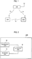
- a mobile communication system according to the first embodiment of the present invention will be described with reference to Figs. 1 to 6 .
- the mobile communication system of the embodiment is an LTE mobile communication system, and includes a core network (not illustrated) and a radio base station eNB connected to the core network as illustrated in Fig. 1 .
- the present invention can also be applied to a cellular mobile communication system in addition to the LTE mobile communication system.
- a mobile station UE#1 is configured to transmit and receive a data signal and a control signal to and from the radio base station eNB through a Uu interface, and to transmit and receive the data signal to and from a mobile station UE#2 through a Ud interface.
- the mobile station UE#2 is configured to transmit and receive the data signal and the control signal to and from the radio base station eNB through the Uu interface, and to transmit and receive the data signal to and from the mobile station UE#1 through the Ud interface.
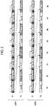
- the radio base station eNB includes an allocation unit 11, a transmission unit 12, and a reception unit 13.
- the allocation unit 11 is configured to allocate an opportunity transmit and receive the data signal to and from the mobile station UE#1 and the mobile station UE#2 through the Uu interface or an opportunity to transmit and receive the data signal to and from the mobile station UE#1 and the mobile station UE#2 through the Ud interface.
- the transmission unit 12 is configured to transmit the data signal and the control signal to the mobile station UE#1 and the mobile station UE# 2 through the Uu interface.
- the transmission unit 12 is configured to transmit a "DL resource allocation" to the mobile station UE#1 and the mobile station UE#2 through a PDCCH in which identification information (C-RNTI: Cell-Radio Network Temporary Identity) is used, and the transmission unit 12 is configured to transmit a "UL grant" to the mobile station UE#1 and the mobile station UE#2 through the Uu interface (PUSCH).
- the "DL resource allocation” notifies the mobile station UE#1 and the mobile station UE#2 that the opportunity (Uu DL) to receive the data signal through the Uu interface (PDSCH) is allocated to the control signal.
- the "UL grant” notifies the mobile station UE#1 and the mobile station UE#2 that the opportunity (Uu UL) to transmit the data signal through the Uu interface (PUSCH).
- the transmission unit 12 is configured to notify the mobile station UE#1 and the mobile station UE#2 that the opportunity (Ud Tx) to transmit the data signal through the Ud interface is allocated through the PDCCH in which common identification information (hereinafter referred to as an X-RNTI) on the mobile station UE#1 and the mobile station UE#2 is used, and to notify the mobile station UE#1 and the mobile station UE#2 that the opportunity (Ud Rx) to receive the data signal through the Ud interface is allocated.
- X-RNTI common identification information
- the use of the X-RNTI common to the mobile station UE#1 and the mobile station UE#2 can reduce a signaling amount related to the PDCCH compared with the case where a C-RNTI is used in each of the mobile station UE#1 and the mobile station UE#2.
- the transmission unit 12 may be configured to previously allocate the X-RNTI to the mobile station UE#1 and the mobile station UE#2 through RRC signaling.
- the mobile station UE#1 and the mobile station UE#2 may be notified of the X-RNTI during a setting of the Ud interface.
- the transmission unit 12 is also configured to transmit the data signal to the mobile station UE#1 and the mobile station UE#2 through the PDSCH in the opportunity allocated by the allocation unit 11.
- each of the mobile station UE#1 and the mobile station UE#2 performs "blind decode" to the PDCCH that is transmitted using the X-RNTI while performing the "blind decode” to the PDCCH that is transmitted using the C-RNTI of itself.
- the reception unit 13 is configured to receive the data signal and the control signal from the mobile station UE#1 and the mobile station UE#2 through the Uu interface.
- the transmission unit 12 is configured to receive the data signal from the mobile station UE#1 and the mobile station UE#2 through the PUSCH in the opportunity allocated by the allocation unit 11.
- the following four cases are considered by a combination of a frequency used in the transmission/reception through the Uu interface and a frequency used in the transmission/reception through the Ud interface.
- a head position of each subframe at a frequency F1 and a head position of each subframe at a frequency F2 are identical to each other (when viewed from the radio base station eNB).
- the present invention can also be applied to the case where the head positions of each subframe at the frequencies F1 and F2 are not identical to each other.
- the transmission/reception through the Ud interface and the transmission/reception of the uplink through the Uu interface are configured to be performed in a time-division manner at the frequency F2.
- the transmission/reception of the downlink through the Uu interface is configured to be performed at the frequency F1.
- the allocation unit 11 is configured to perform the allocation similar to that of the conventional LTE system to the opportunity to perform the transmission/reception of the uplink through the Uu interface and the opportunity to perform the transmission/reception of the downlink through the Uu interface.
- the allocation unit 11 is configured to allocate the PDSCH (that is, the "Uu DL") to the subframe identical to that of the PDCCH, and to allocate the PUSCH (that is, the "Uu UL") to the subframe that is located behind the subframe, to which the PDCCH is allocated, by X subframes.
- the allocation unit 11 is configured to determine the opportunity to perform the transmission/reception through the Ud interface in consideration of a processing delay until the data signal (transport block) is generated in the mobile station UE#1 and the mobile station UE#2.
- the allocation unit 11 is configured to allocate the opportunity to perform the transmission/reception through the Ud interface to the subframe that is located behind the subframe, to which the PDCCH is allocated, by Y (X ⁇ Y) subframes.
- the transmission unit 12 may be configured to transmit "direction information (for example, UE#1 ⁇ UE#2 or UE#2 ⁇ UE#1)", for notifying a direction in which the data signal should be transmitted in the opportunity (subframe) to perform the transmission/reception through the Ud interface, to the mobile station UE#1 and the mobile station UE#2 through the PDCCH.
- direction information for example, UE#1 ⁇ UE#2 or UE#2 ⁇ UE#1
- PDCCH Physical Downlink Control Channel
- the transmission unit 12 may be configured to previously transmit and set the "direction information" notifying the mobile station UE#1 and the mobile station UE#2 of the direction in which the data signal should be transmitted in each subframe to the mobile station UE#1 and the mobile station UE#2 through the RRC signaling. In such cases, the transmission unit 12 needs not to include the "direction information" in the PDCCH.
- the transmission unit 12 may be configured to transmit time-division information to the mobile station UE#1 and the mobile station UE#2 through the RRC signaling.
- the time-division information is necessary to perform the transmission/reception through the Uu interface and the transmission/reception through the Ud interface in the time-division manner.
- the transmission unit 12 is configured to transmit information, which notifies of the subframe to which the opportunity to perform the transmission/reception through the Uu interface is possibly allocated and the subframe to which the opportunity to perform the transmission/reception through the Ud interface is possibly allocated, as time-division information.
- the mobile station UE#1 and the mobile station UE#2 may perform the "blind decode" while being limited to a "DL resource allocation” transmitting PDCCH format and a "UL grant” transmitting PDCCH format, in the subframe (for example, subframes #1, #3, and #5) to which the opportunity to perform the transmission/reception through the Uu interface is possibly allocated.
- the mobile station UE#1 and the mobile station UE#2 may perform the "blind decode" while being limited to the "DL resource allocation” transmitting PDCCH format, a PDCCH format notifying that the opportunity to perform the transmission/reception (UE#1 ⁇ UE#2) through the Ud interface is allocated, and a PDCCH format notifying that the opportunity to perform the transmission/reception (UE#2 ⁇ UE#1) through the Ud interface is allocated, in the subframe (for example, subframes #2, #4, and #6) to which the opportunity to perform the transmission/reception through the Ud interface is possibly allocated.
- the subframe for example, subframes #2, #4, and #6
- the PDCCH format notifying that the opportunity to perform the transmission/reception through the Uu interface is allocated may be configured to be different from the PDCCH format notifying that the opportunity to perform the transmission/reception through the Ud interface is allocated.
- the "DL resource allocation" transmitting PDCCH format may be configured to be different from the "UL grant” transmitting PDCCH format.
- the PDCCH format notifying that the opportunity to perform the transmission/reception (UE#1 ⁇ UE#2) through the Ud interface is allocated may be configured to be different from the PDCCH format notifying that the opportunity to perform the transmission/reception (UE#2 ⁇ UE#1) through the Ud interface is allocated.
- the number of patterns of the "blind decode" performing PDCCH format in the mobile station UE#1 and the mobile station UE#2 can be decreased.
- the mobile station UE#1 and the mobile station UE#2 may perform the "blind decode" in each subframe while being limited to one of a combination of the "DL resource allocation” transmitting PDCCH format and the "UL grant” transmitting PDCCH format, a combination of the "DL resource allocation” transmitting PDCCH format and the PDCCH format notifying that the opportunity to perform the transmission/reception (UE#1 ⁇ UE#2) through the Ud interface is allocated, and a combination of "DL resource allocation” transmitting PDCCH format and the PDCCH format notifying that the opportunity to perform the transmission/reception (UE#2 ⁇ UE#1) through the Ud interface is allocated.
- the number of patterns of the "blind decode" performing PDCCH format in the mobile station UE#1 and the mobile station UE#2 can further be decreased.
- the mobile station UE#1 and the mobile station UE#2 may perform the "blind decode" to the "DL resource allocation” transmitting PDCCH format, the "UL grant” transmitting PDCCH format, the PDCCH format notifying that the opportunity to perform the transmission/reception (UE#1 ⁇ UE#2) through the Ud interface is allocated, and the PDCCH format notifying that the opportunity to perform the transmission/reception (UE#2 ⁇ UE#1) through the Ud interface is allocated.
- the number of patterns of the "blind decode" performing PDCCH format is increased in the mobile station UE#1 and the mobile station UE#2.
- the subframe to which the opportunity to perform the transmission/reception through the Uu interface is allocated and the subframe to which the opportunity to perform the transmission/reception through the Ud interface is possibly allocated are not previously fixed, so that the radio base station eNB can flexibly allocate the opportunity to perform the transmission/reception through the Uu/Ud interface based on a data signal amount and the like.
- the mobile station UE#1 and the mobile station UE#2 need to have an ability to perform not only the transmission through the Uu/Ud interface but also the reception through the Ud interface at the frequency F2. That is, the mobile station UE#1 and the mobile station UE#2 need to support a TDD (Time Divisional Duplexing) function at the frequency F2.
- TDD Time Divisional Duplexing
- the transmission/reception through the Ud interface and the transmission/reception of the downlink through the Uu interface are configured to be performed in the time-division manner at the frequency F1.
- the transmission/reception of the uplink through the Uu interface is configured to be performed at the frequency F2.
- the allocation unit 11 is configured to perform the allocation similar to that of the conventional LTE system to the opportunity to perform the transmission/reception of the uplink through the Uu interface and the opportunity to perform the transmission/reception of the downlink through the Uu interface.
- the allocation unit 11 is configured to allocate the PDSCH (that is, the "Uu DL") to the subframe identical to that of the PDCCH, and to allocate the PUSCH (that is, the "Uu UL") to the subframe that is located behind the subframe, to which the PDCCH is allocated, by X subframes.
- the allocation unit 11 is configured to allocate the opportunity to perform the transmission/reception of the uplink through the Uu interface to the subframe that is located behind the subframe, to which the PDCCH is allocated, by X1 (X ⁇ X1) subframes.
- the allocation unit 11 is configured to perform the PUSCH allocation, which should be performed through the PDCCH in the subframe (for example, subframes #2, #4, #6, and #8) in which the PDCCH cannot be received, using the PDCCH in the subframe (for example, subframes #1, #3, #5, and #7) located ahead by one.
- the allocation unit 11 is configured to determine the opportunity to perform the transmission/reception through the Ud interface in consideration of the processing delay until the data signal (transport block) is generated in the mobile station UE#1 and the mobile station UE#2.
- the allocation unit 11 may be configured to allocate the opportunity to perform the transmission/reception of the uplink through the Ud interface to the subframe that is located behind the subframe, to which the PDCCH is allocated, by Y1 (Y ⁇ Yl) subframes.
- the transmission unit 12 may be configured to notify of the subframe in which the transmission/reception of the data signal should be performed through the Ud interface.
- the transmission unit 12 may be configured to notify of information ("subframe index") indicating how many subframes the allocation of the opportunity to perform the transmission/reception through the Ud interface is located ahead of the subframe, to which the PDCCH is allocated, using a "code point" in a specific field of the PDCCH.
- subframe index information indicating how many subframes the allocation of the opportunity to perform the transmission/reception through the Ud interface is located ahead of the subframe, to which the PDCCH is allocated, using a "code point" in a specific field of the PDCCH.
- the transmission unit 12 may be configured to previously notify of mapping of the "code point" and the "subframe index” through the RRC signaling.
- the mobile station UE#1 and the mobile station UE#2 may be configured to initially set the subframe in which the transmission/reception can be performed through the Ud interface to the subframe in which the transmission/reception of the data signal should be performed through the Ud interface, after a time (X ms) corresponding to the processing delay elapses.
- the mobile station UE#1 and the mobile station UE#2 it is necessary for the mobile station UE#1 and the mobile station UE#2 to have the ability to perform not only the transmission through the Ud interface but also the reception through the Uu/Ud interface at the frequency F1. That is, the mobile station UE#1 and the mobile station UE#2 need to support the TDD function at the frequency F1.
- the mobile station UE#1 and the mobile station UE#2 may be configured to be able to receive the PDCCH even in the subframe in which the mobile station UE#1 and the mobile station UE#2 should perform the transmission/reception of the data signal through the Ud interface.
- the transmission/reception of the data signal through the Ud interface is performed for a remaining time except reception timing (head 1 to 3 OFDM symbols of the subframe) of the PDCCH.
- the transmission/reception of the downlink through the Ud interface is configured to be performed at the frequency F1
- the transmission/reception of the uplink through the Uu interface is configured to be performed at the frequency F2
- the transmission/reception through the Ud interface is configured to be performed at a frequency F3.
- the transmission/reception (UE#1 ⁇ UE#2) through the Ud interface and the transmission/reception (UE#2 ⁇ UE#1) through the Ud interface are configured to be performed in the time-division manner at the frequency F3.
- the allocation unit 11 may be configured to notify of information ("carrier index") indicating the frequency at which the transmission/reception should be performed through the Ud interface using the "code point" in the specific field of the PDCCH.
- the transmission unit 12 may be configured to previously notify of the carrier mapped in each "carrier index" through the RRC signaling.
- the mobile station UE#1 and the mobile station UE#2 it is necessary for the mobile station UE#1 and the mobile station UE#2 to have the ability to perform not only the transmission through the Ud interface but also the reception through the Ud interface at the frequency F3. That is, the mobile station UE#1 and the mobile station UE#2 need to support the TDD function at the frequency F3.
- the transmission/reception of the downlink through the Uu interface is configured to be performed at the frequency F1
- the transmission/reception of the uplink through the Uu interface is configured to be performed at the frequency F2
- the transmission/reception (UE#1 ⁇ UE#2) through the Ud interface is configured to be performed at a frequency F3
- the transmission/reception (UE#2 ⁇ UE#1) through the Ud interface is configured to be performed at a frequency F4.
- the multiplex of the transmission/reception (UE#1 ⁇ UE#2) through the Ud interface and the transmission/reception (UE#2 ⁇ UE#1) through the Ud interface is FDD (Frequency Divisional Duplexing).
- the frequency used in the transmission/reception through the Ud interface is not restricted by the combination of the mobile stations UE as much as possible, but desirably the Ud interface can be set between the mobile stations UE having the equal ability.
- the mobile station UE#1 and the mobile station UE#2 have the ability to perform the transmission/reception through the Ud interface at both the frequencies F3 and F4.
- the mobile station UE#1 and the mobile station UE#2 support the transmission/reception through the Ud interface at a plurality of frequencies (carriers)
- the TDD and the FDD as a method for multiplexing the transmission/reception (UE#1 ⁇ UE#2) through the Ud interface and the transmission/reception (UE#2 ⁇ UE#1) through the Ud interface.
- the radio base station eNB provides the "direction information" to the PDCCH format to enable the flexible allocation according to a traffic amount in each of the transmission/reception (UE#1 ⁇ UE#2) through the Ud interface and the transmission/reception (UE#2 ⁇ UE#1) through the Ud interface.
- frequency (carrier) used in the transmission/reception (UE#1 ⁇ UE#2) through the Ud interface or the transmission/reception (UE#2 ⁇ UE#1) through the Ud interface is notified through the RRC signaling.
- the time-division can quasi-fixedly be changed although the dynamic flexibility is degraded.
- the mobile station UE#1 and the mobile station UE#2 may previously be notified of a definition of the information through the RRC signaling. That is, the mapping of the "direction information" to the transmission/reception may previously be notified through the RRC signaling.
- the PDCCH to which the transmission/reception through the Ud interface is allocated may be restricted so as to indicate the one-way allocation after the "direction information" is set through the RRC signaling.
- the RRC signaling is used again when the direction of the transmission/reception is switched.
- the "direction information" notified through the RRC signaling may be configured to be tied to a periodic time resource or frequency resource.
- the direction of the transmission/reception is determined according to the time and frequency resources allocated by the PDCCH.
- a first feature of the present invention is that a mobile communication method for transmitting and receiving the data signal and the control signal through the Uu interface (radio base station interface) between the mobile station UE#1 (the first mobile station) and the mobile station UE#2 (the second mobile station) and the radio base station eNB, and for transmitting and receiving the data signal through the Ud interface (the inter-mobile station interface) between the mobile station UE#1 and the mobile station UE#2, the mobile communication method includes: a step A in which the radio base station eNB notifies the mobile station UE#1 and the mobile station UE#2 that the opportunity to transmit and receive the data signal through the Ud interface is allocated through the PDCCH (the physical downlink control channel) in which the X-RNTI (the common identification information) is used; and a step B in which the radio base station eNB transmits the "direction information(the transmission direction information) ", for notifying of the direction in which the data signal should be transmitted in the opportunity, to the mobile station UE#1 and the mobile
- a second feature of the present invention is that a radio base station eNB used in the mobile communication system configured to be able to transmit and receive the data signal and the control signal through the Uu interface between the mobile station UE#1 and the mobile station UE#2 and the radio base station eNB, and to transmit and receive the data signal through the Ud interface between the mobile station UE#1 and the mobile station UE#2,
- the radio base station eNB includes a transmission unit 12 configured to notify the mobile station UE#1 and the mobile station UE#2 that the opportunity to transmit and receive the data signal through the Ud interface is allocated through the PDCCH in which the X-RNTI is used, wherein the transmission unit 12 is configured to transmit the "direction information", for notifying of the direction in which the data signal should be transmitted in the opportunity, to the mobile station UE#1 and the mobile station UE#2.
- the transmission unit 12 may be configured to transmit the "direction information" through the PDCCH in which the X-RNTI is used.
- the transmission unit 12 may be configured to transmit the mapping of the transmission and reception of the "direction information", which is transmitted through the PDCCH, through the RRC signaling.
- the transmission unit 12 may be configured to transmit the "direction information" through the RRC signaling.
- the "direction information" may be tied to the periodic time resource and frequency resource.
- the transmission unit 12 may be configured to notify of the frequency, at which the data signal should be transmitted and received through the Ud interface, through the PDCCH in which the X-RNTI is used.
- the transmission unit 12 may be configured to notify of the frequency, at which the data signal should be transmitted and received through the Ud interface, through the RRC signaling.
- the transmission unit 12 may be configured to notify of the subframe, to which the data signal should be transmitted and received through the Ud interface, through the PDCCH in which the X-RNTI is used.
- the transmission unit 12 may be configured to transmit and receive the data signal and the control signal through the Uu interface through the RRC signaling, and to transmit the time-division information necessary to transmit and receive the data signal in the time-division manner through the Ud interface through the RRC signaling.
- the transmission unit 12 may be configured such that the PDCCH format, for notifying the opportunity to transmit and receive the data signal through the Uu interface is allocated, is different from the PDCCH format, for notifying the opportunity to transmit and receive the data signal through the Ud interface is allocated.
- the operations of the radio base station eNB and the mobile stations UE#1 and UE#2 may be performed by hardware, a software module executed by a processor, or a combination thereof.
- the software module may be provided in any type of storage medium such as a RAM (Random Access Memory), a flash memory, a ROM (Read Only Memory), an EPROM (Erasable Programmable ROM), an EEPROM (Electronically Erasable and Programmable ROM), a register, a hard disk, a removable disk, and a CD-ROM.
- RAM Random Access Memory
- flash memory a ROM (Read Only Memory)
- EPROM Erasable Programmable ROM
- EEPROM Electrically Erasable and Programmable ROM
- register a hard disk, a removable disk, and a CD-ROM.
- the storage medium is connected to the processor such that the processor can read and write the information in and from the storage medium.
- the storage medium may be integrated in the processor.
- the storage medium may be provided in an ASIC.
- the ASIC may be provided in the radio base station eNB or the mobile stations UE#1 and UE#2.
- the storage medium and the processor may be provided as a discrete component in the radio base station eNB or the mobile stations UE#1 and UE#.
- the present invention can provide the mobile communication method and the radio base station, which can properly adjust the transmission/reception timing of the data signal and the control signal through the Uu interface and the transmission/reception timing of the data signal through the Ud interface.
Landscapes
- Engineering & Computer Science (AREA)
- Signal Processing (AREA)
- Computer Networks & Wireless Communication (AREA)
- Mobile Radio Communication Systems (AREA)
Claims (8)
- Mobilkommunikationsverfahren zum Übertragen und Empfangen eines Datensignals und eines Steuersignals über eine Funkbasisstationsschnittstelle (Uu) zwischen einer ersten Mobilstation (UE#1) und einer zweiten Mobilstation (UE#2) und einer Funkbasisstation (eNB) und zum Übertragen und Empfangen eines Datensignals über eine Zwischenmobilstationsschnittstelle (Ud) zwischen der ersten Mobilstation (UE#1) und der zweiten Mobilstation (UE#2), wobei der ersten und der zweiten Mobilstation (UE#1, UE#2) eine gemeinsame Identifikationsinformation, X-RNTI, zugewiesen ist, wobei das Mobilkommunikationsverfahren umfasst:- Verwenden eines ersten Trägers, der eine erste Frequenz einsetzt, zum Downlink über die Funkbasisstationsschnittstelle (Uu);- Verwenden eines zweiten Trägers, der eine zweite Frequenz einsetzt, zum Uplink über die Funkbasisstationsschnittstelle (Uu);- Verwenden entweder des ersten Trägers oder des zweiten Trägers zum Übertragen und Empfangen des Datensignals über die Zwischenmobilstationsschnittstelle (Ud);- a) durch die Funkbasisstation (eNB), um der ersten Mobilstation (UE#1) und der zweiten Mobilstation (UE#2) zu melden, dass eine Möglichkeit (Ud Tx, Ud Rx), das Datensignal über die Zwischenmobilstationsschnittstelle (Ud) zu übertragen und zu empfangen, unter Verwendung des ersten Trägers, in dem die gemeinsame Identifikationsinformation, X-RNTI, über die erste und die zweite Mobilstation (UE#1, UE#2) verwendet wird, über einen physikalischen Downlink-Steuerkanal (PDCCH) zugewiesen wird;- b) durch die Funkbasisstation (eNB), um eine Übertragungsrichtungsinformation (UE#1->UE#2; UE#1<-UE#2) zum Melden einer Richtung, in der das Datensignal bei der zugewiesenen Möglichkeit übertragen werden sollte, an die erste Mobilstation (UE#1) und die zweite Mobilstation (UE#2), durch RRC-Signalisierung zu übertragen; und- durch die Funkbasisstation (eNB), um eine Zeitmultiplexinformation, die erforderlich ist, um das Datensignal und das Steuersignal über die Funkbasisstationsschnittstelle (Uu) zu übertragen zu empfangen und das Datensignal über die Zwischenmobilstationsschnittstelle (Ud) in einer Zeitmultiplex-Weise zu übertragen und zu empfangen, durch RRC-Signalisierung zu übertragen.
- Funkbasisstation (eNB), die in einem Mobilkommunikationssystem verwendet wird, das dazu ausgebildet ist, in der Lage zu sein, ein Datensignal und ein Steuersignal über eine Funkbasisstationsschnittstelle (Uu) zwischen einer ersten Mobilstation (UE#1) und einer zweiten Mobilstation (UE#2) und der Funkbasisstation (eNB) zu übertragen und zu empfangen und ein Datensignal über eine Zwischenmobilstationsschnittstelle (Ud) zwischen der ersten Mobilstation (UE#1) und der zweiten Mobilstation (UE#2) zu übertragen und zu empfangen, wobei der ersten und der zweiten Mobilstation (UE#1, UE#2) eine gemeinsame Identifikationsinformation, X-RNTI, zugewiesen ist, wobei die Funkbasisstation (eNB) umfasst:- eine Übertragungseinheit (12), die dazu ausgebildet ist, das Datensignal und das Steuersignal unter Verwendung eines ersten Trägers, der eine erste Frequenz einsetzt, über die Funkbasisstationsschnittstelle (Uu) an die erste Mobilstation (UE#1) und eine zweite Mobilstation (UE#2) zu übertragen; und- eine Empfangseinheit (13), die dazu ausgebildet ist, das Datensignal und das Steuersignal unter Verwendung eines zweiten Trägers, der eine zweite Frequenz einsetzt, über die Funkbasisstationsschnittstelle (Uu) von der ersten Mobilstation (UE#1) und einer zweiten Mobilstation (UE#2) zu empfangen; wobei- entweder der erste Träger oder der zweite Träger zum Übertragen und Empfangen des Datensignals über die Zwischenmobilstationsschnittstelle (Ud) verwendet wird;- die Übertragungseinheit (12) dazu ausgebildet ist, der ersten Mobilstation (UE#1) und der zweiten Mobilstation (UE#2) zu melden, dass eine Möglichkeit, das Datensignal über die Zwischenmobilstationsschnittstelle (Ud) zu übertragen und zu empfangen, unter Verwendung des ersten Trägers, in dem eine gemeinsame Identifikationsinformation verwendet wird, über einen physikalischen Downlink-Steuerkanal (PDDCH) zugewiesen wird;- die Übertragungseinheit (12) dazu ausgebildet ist, eine Übertragungsrichtungsinformation (UE#1->UE#2; UE#1<-UE#2) zum Melden einer Richtung, in der das Datensignal bei der zugewiesenen Möglichkeit übertragen werden sollte, durch RRC-Signalisierung an die erste Mobilstation (UE#1->UE#2; UE#1<-UE#2) und die zweite Mobilstation (UE#1->UE#2; UE#1<-UE#2) zu übertragen; und- die Übertragungseinheit (12) dazu ausgebildet ist, eine Zeitmultiplexinformation, die erforderlich ist, um das Datensignal und das Steuersignal über die Funkbasisstationsschnittstelle (Uu) zu übertragen und zu empfangen und das Datensignal über die Zwischenmobilstationsschnittstelle (Ud) in einer Zeitmultiplex-Weise zu übertragen und zu empfangen, durch RRC-Signalisierung an die erste Mobilstation (UE#1) und eine zweite Mobilstation (UE#2) zu übertragen.
- Funkbasisstation (eNB) nach Anspruch 2, wobei die Übertragungsrichtungsinformation an eine periodische Zeitressource und Frequenzressource gebunden ist, sodass die Übertragungsrichtung entsprechend der Zeit und Frequenz, die dem physikalischen Downlink-Steuerkanal (PDCCH) zugewiesen sind, bestimmt wird.
- Funkbasisstation (eNB) nach Anspruch 2, wobei die Übertragungseinheit (12) dazu ausgebildet ist, eine Frequenz (F1, F2, F3, F4), mit der das Datensignal über die Zwischenmobilstationsschnittstelle (Ud) übertragen und empfangen werden sollte, über den physikalischen Downlink-Steuerkanal (PDCCH) zu melden.
- Funkbasisstation (eNB) nach Anspruch 2, wobei die Übertragungseinheit (12) dazu ausgebildet ist, eine Frequenz, mit der das Datensignal über die Zwischenmobilstationsschnittstelle (Ud) übertragen und empfangen werden sollte, durch RRC-Signalisierung zu melden.
- Funkbasisstation (eNB) nach Anspruch 2, wobei die Übertragungseinheit (12) dazu ausgebildet ist, einen Subframe (#1-#8), an den das Datensignal über die Zwischenmobilstationsschnittstelle (Ud) übertragen und empfangen werden sollte, über den physikalischen Downlink-Steuerkanal (PDCCH) zu melden.
- Funkbasisstation (eNB) nach Anspruch 2, wobei die Übertragungseinheit (12) dazu ausgebildet ist, das Datensignal und das Steuersignal durch RRC-Signalisierung über die Funkbasisstationsschnittstelle (Uu) zu übertragen und zu empfangen und eine Zeitmultiplexinformation, die erforderlich ist, um das Datensignal in einer Zeitmultiplexmethode über die Zwischenmobilstationsschnittstelle (Ud) zu übertragen und zu empfangen, durch die RRC-Signalisierung zu übertragen.
- Funkbasisstation (eNB) nach Anspruch 2, wobei die Übertragungseinheit (12) so ausgebildet ist, dass ein Format des physikalischen Downlink-Steuerkanals (PDCCH) zum Melden, dass die Möglichkeit, das Datensignal über die Funkbasisstationsschnittstelle (Uu) zu übertragen und zu empfangen, zugewiesen ist, sich unterscheidet von einem Format eines physikalischen Downlink-Steuerkanals (PDCCH) zum Melden, dass die Möglichkeit, das Datensignal über die Zwischenmobilstationsschnittstelle (Ud) zu übertragen und zu empfangen, zugewiesen ist.
Applications Claiming Priority (2)
| Application Number | Priority Date | Filing Date | Title |
|---|---|---|---|
| JP2011111921A JP5484396B2 (ja) | 2011-05-18 | 2011-05-18 | 移動通信方法及び無線基地局 |
| PCT/JP2012/061941 WO2012157499A1 (ja) | 2011-05-18 | 2012-05-10 | 移動通信方法及び無線基地局 |
Publications (3)
| Publication Number | Publication Date |
|---|---|
| EP2712251A1 EP2712251A1 (de) | 2014-03-26 |
| EP2712251A4 EP2712251A4 (de) | 2014-10-29 |
| EP2712251B1 true EP2712251B1 (de) | 2017-08-02 |
Family
ID=47176829
Family Applications (1)
| Application Number | Title | Priority Date | Filing Date |
|---|---|---|---|
| EP12786525.1A Active EP2712251B1 (de) | 2011-05-18 | 2012-05-10 | Mobiles kommunikationsverfahren und drahtlose basisstation |
Country Status (4)
| Country | Link |
|---|---|
| US (2) | US9544106B2 (de) |
| EP (1) | EP2712251B1 (de) |
| JP (1) | JP5484396B2 (de) |
| WO (1) | WO2012157499A1 (de) |
Families Citing this family (7)
| Publication number | Priority date | Publication date | Assignee | Title |
|---|---|---|---|---|
| JP5484396B2 (ja) | 2011-05-18 | 2014-05-07 | 株式会社Nttドコモ | 移動通信方法及び無線基地局 |
| CN103037359A (zh) | 2011-09-30 | 2013-04-10 | 华为技术有限公司 | 一种实现设备到设备的通讯方法、终端及系统 |
| EP3621272B1 (de) | 2013-01-25 | 2022-04-13 | Koninklijke KPN N.V. | Netzwerkuntersützte näherungserkennung von kommunikationsvorrichtungen, authentifizierung und verbindungseinrichtungen zwischen mobilen kommunikationsvorrichtungen in 3gpp lte |
| CN103974431B (zh) * | 2013-02-06 | 2018-11-09 | 索尼公司 | 无线通信方法、基站以及无线通信设备 |
| GB2518168A (en) * | 2013-09-11 | 2015-03-18 | Nec Corp | Communication system |
| JP6476476B2 (ja) * | 2014-04-22 | 2019-03-06 | 富士通コネクテッドテクノロジーズ株式会社 | 無線端末、無線局、無線通信システム、および無線通信方法 |
| EP3414965B1 (de) | 2016-03-24 | 2021-05-19 | LG Electronics Inc. | Verfahren zum senden von daten in einem kommunikationssystem und vorrichtung dafür |
Family Cites Families (15)
| Publication number | Priority date | Publication date | Assignee | Title |
|---|---|---|---|---|
| FI97519C (fi) | 1993-08-26 | 1996-12-27 | Nokia Telecommunications Oy | Menetelmä tilaaja-asemien ohjaamiseksi radiopuhelinjärjestelmässä, radiopuhelinjärjestelmä ja radiopuhelinjärjestelmän tilaaja-asema |
| EP1389884A1 (de) | 2002-08-13 | 2004-02-18 | Siemens Aktiengesellschaft | Verfahren zum Betrieb eines Funksystems mittels Richtantennen sowie sendende Station und Funksystem |
| EP1389856A1 (de) * | 2002-08-13 | 2004-02-18 | Siemens Aktiengesellschaft | Verfahren zur Vergabe von Funkressourcen in einem selbstorganidierenden Funkkommunikationssystem |
| JP2004165881A (ja) * | 2002-11-12 | 2004-06-10 | Matsushita Electric Ind Co Ltd | デジタル無線通信装置 |
| CN1549612A (zh) * | 2003-05-19 | 2004-11-24 | 皇家飞利浦电子股份有限公司 | 无线通信网络中点到点对等通信的上行链路同步保持的方法和装置 |
| US8159999B2 (en) | 2005-01-25 | 2012-04-17 | Interdigital Technology Corporation | Peer-to-peer wireless communication system |
| US8600336B2 (en) | 2005-09-12 | 2013-12-03 | Qualcomm Incorporated | Scheduling with reverse direction grant in wireless communication systems |
| TWI463894B (zh) * | 2006-10-27 | 2014-12-01 | 內數位科技公司 | 無線系統中增強不連續接收方法及裝置 |
| US9900779B2 (en) * | 2008-12-30 | 2018-02-20 | Qualcomm Incorporated | Centralized control of peer-to-peer communication |
| US8913511B2 (en) * | 2010-04-01 | 2014-12-16 | Qualcomm Incorporated | Interference management to support peer-to-peer communication in a wide area network |
| US8401562B2 (en) * | 2010-11-17 | 2013-03-19 | Nokia Corporation | Apparatus and method employing scheduler behavior aware predictive resource selection in a communication system |
| US8744458B2 (en) * | 2010-11-19 | 2014-06-03 | Nokia Corporation | Signaling mixed resource allocations for D2D communications |
| US20120201158A1 (en) * | 2011-02-03 | 2012-08-09 | Qualcomm Incorporated | Peer-to-peer / wan association control and resource coordination for mobile entities using aggregate neighborhood utility metrics |
| US20120281679A1 (en) * | 2011-05-02 | 2012-11-08 | Renesas Mobile Corporation | RACH communication in cellular system |
| JP5484396B2 (ja) | 2011-05-18 | 2014-05-07 | 株式会社Nttドコモ | 移動通信方法及び無線基地局 |
-
2011
- 2011-05-18 JP JP2011111921A patent/JP5484396B2/ja active Active
-
2012
- 2012-05-10 EP EP12786525.1A patent/EP2712251B1/de active Active
- 2012-05-10 WO PCT/JP2012/061941 patent/WO2012157499A1/ja not_active Ceased
- 2012-05-10 US US14/118,299 patent/US9544106B2/en active Active
-
2016
- 2016-11-29 US US15/363,224 patent/US20170078057A1/en not_active Abandoned
Non-Patent Citations (1)
| Title |
|---|
| None * |
Also Published As
| Publication number | Publication date |
|---|---|
| US9544106B2 (en) | 2017-01-10 |
| US20170078057A1 (en) | 2017-03-16 |
| WO2012157499A1 (ja) | 2012-11-22 |
| JP5484396B2 (ja) | 2014-05-07 |
| EP2712251A1 (de) | 2014-03-26 |
| JP2012244366A (ja) | 2012-12-10 |
| US20140204852A1 (en) | 2014-07-24 |
| EP2712251A4 (de) | 2014-10-29 |
Similar Documents
| Publication | Publication Date | Title |
|---|---|---|
| US12538355B2 (en) | Multiple starting and ending positions for scheduled or autonomous uplink transmission in unlicensed spectrum | |
| KR102321890B1 (ko) | 시간-주파수 자원의 송신 방향을 구성하는 방법, 및 장치 | |
| US20250024440A1 (en) | User equipment, base station and wireless communication method | |
| US9635653B2 (en) | Switching between downlink and uplink | |
| CN108173633B (zh) | 接收上行参考信号的方法和装置 | |
| US20170078057A1 (en) | Mobile communication method and radio base station | |
| US9521639B2 (en) | Mobile communication system | |
| CN110830220B (zh) | 通信方法和通信装置 | |
| CN114710833A (zh) | 一种资源管理方法及相关设备 | |
| WO2017113077A1 (zh) | 一种上行紧急业务传输方法、基站、用户设备及系统 | |
| US12185378B2 (en) | Systems and methods of enhanced random access procedure using information element containing configured parameters | |
| EP2941031B1 (de) | Mobilstation und radio basisstation | |
| AU2019474027B2 (en) | Methods, devices and computer readable media for communication on unlicensed band | |
| EP2892263B1 (de) | Drahtlose basisstation und mobilstation | |
| EP3503652A1 (de) | Ressourcenbestimmungsverfahren, basisstation und mobilstation | |
| KR102199873B1 (ko) | 무선 통신 방법 및 장치 | |
| US12015568B2 (en) | Base station, method, program, and recording medium | |
| CN116671204B (zh) | 无线通信的方法和装置 | |
| CN114430929B (zh) | 用于传输的资源重新调度 | |
| CN109831824A (zh) | 用于上行捎带传输的方法、装置及系统 | |
| WO2017174125A1 (en) | Method, system and apparatus | |
| JP2011066528A (ja) | 無線基地局 |
Legal Events
| Date | Code | Title | Description |
|---|---|---|---|
| PUAI | Public reference made under article 153(3) epc to a published international application that has entered the european phase |
Free format text: ORIGINAL CODE: 0009012 |
|
| 17P | Request for examination filed |
Effective date: 20131203 |
|
| AK | Designated contracting states |
Kind code of ref document: A1 Designated state(s): AL AT BE BG CH CY CZ DE DK EE ES FI FR GB GR HR HU IE IS IT LI LT LU LV MC MK MT NL NO PL PT RO RS SE SI SK SM TR |
|
| DAX | Request for extension of the european patent (deleted) | ||
| A4 | Supplementary search report drawn up and despatched |
Effective date: 20141001 |
|
| RIC1 | Information provided on ipc code assigned before grant |
Ipc: H04W 92/18 20090101ALI20140926BHEP Ipc: H04W 72/04 20090101AFI20140926BHEP |
|
| 17Q | First examination report despatched |
Effective date: 20160525 |
|
| GRAP | Despatch of communication of intention to grant a patent |
Free format text: ORIGINAL CODE: EPIDOSNIGR1 |
|
| INTG | Intention to grant announced |
Effective date: 20170301 |
|
| GRAS | Grant fee paid |
Free format text: ORIGINAL CODE: EPIDOSNIGR3 |
|
| GRAA | (expected) grant |
Free format text: ORIGINAL CODE: 0009210 |
|
| AK | Designated contracting states |
Kind code of ref document: B1 Designated state(s): AL AT BE BG CH CY CZ DE DK EE ES FI FR GB GR HR HU IE IS IT LI LT LU LV MC MK MT NL NO PL PT RO RS SE SI SK SM TR |
|
| REG | Reference to a national code |
Ref country code: CH Ref legal event code: EP Ref country code: AT Ref legal event code: REF Ref document number: 915715 Country of ref document: AT Kind code of ref document: T Effective date: 20170815 |
|
| REG | Reference to a national code |
Ref country code: IE Ref legal event code: FG4D |
|
| REG | Reference to a national code |
Ref country code: DE Ref legal event code: R096 Ref document number: 602012035381 Country of ref document: DE |
|
| REG | Reference to a national code |
Ref country code: NL Ref legal event code: MP Effective date: 20170802 |
|
| REG | Reference to a national code |
Ref country code: AT Ref legal event code: MK05 Ref document number: 915715 Country of ref document: AT Kind code of ref document: T Effective date: 20170802 |
|
| REG | Reference to a national code |
Ref country code: LT Ref legal event code: MG4D |
|
| PG25 | Lapsed in a contracting state [announced via postgrant information from national office to epo] |
Ref country code: SE Free format text: LAPSE BECAUSE OF FAILURE TO SUBMIT A TRANSLATION OF THE DESCRIPTION OR TO PAY THE FEE WITHIN THE PRESCRIBED TIME-LIMIT Effective date: 20170802 Ref country code: AT Free format text: LAPSE BECAUSE OF FAILURE TO SUBMIT A TRANSLATION OF THE DESCRIPTION OR TO PAY THE FEE WITHIN THE PRESCRIBED TIME-LIMIT Effective date: 20170802 Ref country code: HR Free format text: LAPSE BECAUSE OF FAILURE TO SUBMIT A TRANSLATION OF THE DESCRIPTION OR TO PAY THE FEE WITHIN THE PRESCRIBED TIME-LIMIT Effective date: 20170802 Ref country code: NL Free format text: LAPSE BECAUSE OF FAILURE TO SUBMIT A TRANSLATION OF THE DESCRIPTION OR TO PAY THE FEE WITHIN THE PRESCRIBED TIME-LIMIT Effective date: 20170802 Ref country code: NO Free format text: LAPSE BECAUSE OF FAILURE TO SUBMIT A TRANSLATION OF THE DESCRIPTION OR TO PAY THE FEE WITHIN THE PRESCRIBED TIME-LIMIT Effective date: 20171102 Ref country code: LT Free format text: LAPSE BECAUSE OF FAILURE TO SUBMIT A TRANSLATION OF THE DESCRIPTION OR TO PAY THE FEE WITHIN THE PRESCRIBED TIME-LIMIT Effective date: 20170802 Ref country code: FI Free format text: LAPSE BECAUSE OF FAILURE TO SUBMIT A TRANSLATION OF THE DESCRIPTION OR TO PAY THE FEE WITHIN THE PRESCRIBED TIME-LIMIT Effective date: 20170802 |
|
| PG25 | Lapsed in a contracting state [announced via postgrant information from national office to epo] |
Ref country code: RS Free format text: LAPSE BECAUSE OF FAILURE TO SUBMIT A TRANSLATION OF THE DESCRIPTION OR TO PAY THE FEE WITHIN THE PRESCRIBED TIME-LIMIT Effective date: 20170802 Ref country code: ES Free format text: LAPSE BECAUSE OF FAILURE TO SUBMIT A TRANSLATION OF THE DESCRIPTION OR TO PAY THE FEE WITHIN THE PRESCRIBED TIME-LIMIT Effective date: 20170802 Ref country code: GR Free format text: LAPSE BECAUSE OF FAILURE TO SUBMIT A TRANSLATION OF THE DESCRIPTION OR TO PAY THE FEE WITHIN THE PRESCRIBED TIME-LIMIT Effective date: 20171103 Ref country code: PL Free format text: LAPSE BECAUSE OF FAILURE TO SUBMIT A TRANSLATION OF THE DESCRIPTION OR TO PAY THE FEE WITHIN THE PRESCRIBED TIME-LIMIT Effective date: 20170802 Ref country code: LV Free format text: LAPSE BECAUSE OF FAILURE TO SUBMIT A TRANSLATION OF THE DESCRIPTION OR TO PAY THE FEE WITHIN THE PRESCRIBED TIME-LIMIT Effective date: 20170802 Ref country code: IS Free format text: LAPSE BECAUSE OF FAILURE TO SUBMIT A TRANSLATION OF THE DESCRIPTION OR TO PAY THE FEE WITHIN THE PRESCRIBED TIME-LIMIT Effective date: 20171202 Ref country code: BG Free format text: LAPSE BECAUSE OF FAILURE TO SUBMIT A TRANSLATION OF THE DESCRIPTION OR TO PAY THE FEE WITHIN THE PRESCRIBED TIME-LIMIT Effective date: 20171102 |
|
| PG25 | Lapsed in a contracting state [announced via postgrant information from national office to epo] |
Ref country code: DK Free format text: LAPSE BECAUSE OF FAILURE TO SUBMIT A TRANSLATION OF THE DESCRIPTION OR TO PAY THE FEE WITHIN THE PRESCRIBED TIME-LIMIT Effective date: 20170802 Ref country code: CZ Free format text: LAPSE BECAUSE OF FAILURE TO SUBMIT A TRANSLATION OF THE DESCRIPTION OR TO PAY THE FEE WITHIN THE PRESCRIBED TIME-LIMIT Effective date: 20170802 Ref country code: RO Free format text: LAPSE BECAUSE OF FAILURE TO SUBMIT A TRANSLATION OF THE DESCRIPTION OR TO PAY THE FEE WITHIN THE PRESCRIBED TIME-LIMIT Effective date: 20170802 |
|
| REG | Reference to a national code |
Ref country code: DE Ref legal event code: R097 Ref document number: 602012035381 Country of ref document: DE |
|
| PG25 | Lapsed in a contracting state [announced via postgrant information from national office to epo] |
Ref country code: SK Free format text: LAPSE BECAUSE OF FAILURE TO SUBMIT A TRANSLATION OF THE DESCRIPTION OR TO PAY THE FEE WITHIN THE PRESCRIBED TIME-LIMIT Effective date: 20170802 Ref country code: SM Free format text: LAPSE BECAUSE OF FAILURE TO SUBMIT A TRANSLATION OF THE DESCRIPTION OR TO PAY THE FEE WITHIN THE PRESCRIBED TIME-LIMIT Effective date: 20170802 Ref country code: EE Free format text: LAPSE BECAUSE OF FAILURE TO SUBMIT A TRANSLATION OF THE DESCRIPTION OR TO PAY THE FEE WITHIN THE PRESCRIBED TIME-LIMIT Effective date: 20170802 Ref country code: IT Free format text: LAPSE BECAUSE OF FAILURE TO SUBMIT A TRANSLATION OF THE DESCRIPTION OR TO PAY THE FEE WITHIN THE PRESCRIBED TIME-LIMIT Effective date: 20170802 |
|
| PLBE | No opposition filed within time limit |
Free format text: ORIGINAL CODE: 0009261 |
|
| STAA | Information on the status of an ep patent application or granted ep patent |
Free format text: STATUS: NO OPPOSITION FILED WITHIN TIME LIMIT |
|
| 26N | No opposition filed |
Effective date: 20180503 |
|
| PG25 | Lapsed in a contracting state [announced via postgrant information from national office to epo] |
Ref country code: SI Free format text: LAPSE BECAUSE OF FAILURE TO SUBMIT A TRANSLATION OF THE DESCRIPTION OR TO PAY THE FEE WITHIN THE PRESCRIBED TIME-LIMIT Effective date: 20170802 |
|
| REG | Reference to a national code |
Ref country code: CH Ref legal event code: PL |
|
| GBPC | Gb: european patent ceased through non-payment of renewal fee |
Effective date: 20180510 |
|
| REG | Reference to a national code |
Ref country code: BE Ref legal event code: MM Effective date: 20180531 |
|
| PG25 | Lapsed in a contracting state [announced via postgrant information from national office to epo] |
Ref country code: MC Free format text: LAPSE BECAUSE OF FAILURE TO SUBMIT A TRANSLATION OF THE DESCRIPTION OR TO PAY THE FEE WITHIN THE PRESCRIBED TIME-LIMIT Effective date: 20170802 |
|
| REG | Reference to a national code |
Ref country code: IE Ref legal event code: MM4A |
|
| PG25 | Lapsed in a contracting state [announced via postgrant information from national office to epo] |
Ref country code: LI Free format text: LAPSE BECAUSE OF NON-PAYMENT OF DUE FEES Effective date: 20180531 Ref country code: CH Free format text: LAPSE BECAUSE OF NON-PAYMENT OF DUE FEES Effective date: 20180531 |
|
| PG25 | Lapsed in a contracting state [announced via postgrant information from national office to epo] |
Ref country code: LU Free format text: LAPSE BECAUSE OF NON-PAYMENT OF DUE FEES Effective date: 20180510 |
|
| PG25 | Lapsed in a contracting state [announced via postgrant information from national office to epo] |
Ref country code: FR Free format text: LAPSE BECAUSE OF NON-PAYMENT OF DUE FEES Effective date: 20180531 Ref country code: IE Free format text: LAPSE BECAUSE OF NON-PAYMENT OF DUE FEES Effective date: 20180510 Ref country code: GB Free format text: LAPSE BECAUSE OF NON-PAYMENT OF DUE FEES Effective date: 20180510 |
|
| PG25 | Lapsed in a contracting state [announced via postgrant information from national office to epo] |
Ref country code: BE Free format text: LAPSE BECAUSE OF NON-PAYMENT OF DUE FEES Effective date: 20180531 |
|
| PG25 | Lapsed in a contracting state [announced via postgrant information from national office to epo] |
Ref country code: MT Free format text: LAPSE BECAUSE OF NON-PAYMENT OF DUE FEES Effective date: 20180510 |
|
| PG25 | Lapsed in a contracting state [announced via postgrant information from national office to epo] |
Ref country code: TR Free format text: LAPSE BECAUSE OF FAILURE TO SUBMIT A TRANSLATION OF THE DESCRIPTION OR TO PAY THE FEE WITHIN THE PRESCRIBED TIME-LIMIT Effective date: 20170802 |
|
| PG25 | Lapsed in a contracting state [announced via postgrant information from national office to epo] |
Ref country code: HU Free format text: LAPSE BECAUSE OF FAILURE TO SUBMIT A TRANSLATION OF THE DESCRIPTION OR TO PAY THE FEE WITHIN THE PRESCRIBED TIME-LIMIT; INVALID AB INITIO Effective date: 20120510 Ref country code: PT Free format text: LAPSE BECAUSE OF FAILURE TO SUBMIT A TRANSLATION OF THE DESCRIPTION OR TO PAY THE FEE WITHIN THE PRESCRIBED TIME-LIMIT Effective date: 20170802 |
|
| PG25 | Lapsed in a contracting state [announced via postgrant information from national office to epo] |
Ref country code: CY Free format text: LAPSE BECAUSE OF FAILURE TO SUBMIT A TRANSLATION OF THE DESCRIPTION OR TO PAY THE FEE WITHIN THE PRESCRIBED TIME-LIMIT Effective date: 20170802 Ref country code: MK Free format text: LAPSE BECAUSE OF NON-PAYMENT OF DUE FEES Effective date: 20170802 |
|
| PG25 | Lapsed in a contracting state [announced via postgrant information from national office to epo] |
Ref country code: AL Free format text: LAPSE BECAUSE OF FAILURE TO SUBMIT A TRANSLATION OF THE DESCRIPTION OR TO PAY THE FEE WITHIN THE PRESCRIBED TIME-LIMIT Effective date: 20170802 |
|
| P01 | Opt-out of the competence of the unified patent court (upc) registered |
Effective date: 20230510 |
|
| PGFP | Annual fee paid to national office [announced via postgrant information from national office to epo] |
Ref country code: DE Payment date: 20250521 Year of fee payment: 14 |