EP2712760A1 - Vorrichtung und Methode zur Erfassung des Reifenabriebs auf der Fahrbahn - Google Patents
Vorrichtung und Methode zur Erfassung des Reifenabriebs auf der Fahrbahn Download PDFInfo
- Publication number
- EP2712760A1 EP2712760A1 EP12290320.6A EP12290320A EP2712760A1 EP 2712760 A1 EP2712760 A1 EP 2712760A1 EP 12290320 A EP12290320 A EP 12290320A EP 2712760 A1 EP2712760 A1 EP 2712760A1
- Authority
- EP
- European Patent Office
- Prior art keywords
- branch
- rotation
- vehicle
- section
- wheel
- Prior art date
- Legal status (The legal status is an assumption and is not a legal conclusion. Google has not performed a legal analysis and makes no representation as to the accuracy of the status listed.)
- Withdrawn
Links
- 238000000034 method Methods 0.000 title claims abstract description 12
- 238000001514 detection method Methods 0.000 claims description 46
- 230000008878 coupling Effects 0.000 claims description 20
- 238000010168 coupling process Methods 0.000 claims description 20
- 238000005859 coupling reaction Methods 0.000 claims description 20
- 238000005259 measurement Methods 0.000 claims description 11
- 230000011664 signaling Effects 0.000 claims description 6
- 230000005540 biological transmission Effects 0.000 claims description 3
- 238000004458 analytical method Methods 0.000 description 8
- 238000012423 maintenance Methods 0.000 description 6
- XEEYBQQBJWHFJM-UHFFFAOYSA-N Iron Chemical compound [Fe] XEEYBQQBJWHFJM-UHFFFAOYSA-N 0.000 description 4
- 230000005764 inhibitory process Effects 0.000 description 3
- 238000013459 approach Methods 0.000 description 2
- 230000036461 convulsion Effects 0.000 description 2
- 230000002596 correlated effect Effects 0.000 description 2
- 238000009434 installation Methods 0.000 description 2
- 229910052742 iron Inorganic materials 0.000 description 2
- 230000009466 transformation Effects 0.000 description 2
- 241000861223 Issus Species 0.000 description 1
- 229920000297 Rayon Polymers 0.000 description 1
- 230000001133 acceleration Effects 0.000 description 1
- 230000008859 change Effects 0.000 description 1
- 230000001276 controlling effect Effects 0.000 description 1
- 230000007423 decrease Effects 0.000 description 1
- 230000037213 diet Effects 0.000 description 1
- 235000005911 diet Nutrition 0.000 description 1
- 238000006073 displacement reaction Methods 0.000 description 1
- 238000009826 distribution Methods 0.000 description 1
- 229940082150 encore Drugs 0.000 description 1
- 239000003517 fume Substances 0.000 description 1
- 238000010438 heat treatment Methods 0.000 description 1
- 230000003137 locomotive effect Effects 0.000 description 1
- 238000004519 manufacturing process Methods 0.000 description 1
- 230000013011 mating Effects 0.000 description 1
- 230000003287 optical effect Effects 0.000 description 1
- 230000002028 premature Effects 0.000 description 1
- 238000012545 processing Methods 0.000 description 1
- 239000002964 rayon Substances 0.000 description 1
- 238000005096 rolling process Methods 0.000 description 1
- 238000005070 sampling Methods 0.000 description 1
- 238000009987 spinning Methods 0.000 description 1
- 230000001360 synchronised effect Effects 0.000 description 1
- 231100000331 toxic Toxicity 0.000 description 1
- 230000002588 toxic effect Effects 0.000 description 1
- 230000001131 transforming effect Effects 0.000 description 1
- 230000001960 triggered effect Effects 0.000 description 1
- 238000011144 upstream manufacturing Methods 0.000 description 1
Images

Classifications
-
- B—PERFORMING OPERATIONS; TRANSPORTING
- B60—VEHICLES IN GENERAL
- B60T—VEHICLE BRAKE CONTROL SYSTEMS OR PARTS THEREOF; BRAKE CONTROL SYSTEMS OR PARTS THEREOF, IN GENERAL; ARRANGEMENT OF BRAKING ELEMENTS ON VEHICLES IN GENERAL; PORTABLE DEVICES FOR PREVENTING UNWANTED MOVEMENT OF VEHICLES; VEHICLE MODIFICATIONS TO FACILITATE COOLING OF BRAKES
- B60T8/00—Arrangements for adjusting wheel-braking force to meet varying vehicular or ground-surface conditions, e.g. limiting or varying distribution of braking force
- B60T8/17—Using electrical or electronic regulation means to control braking
- B60T8/172—Determining control parameters used in the regulation, e.g. by calculations involving measured or detected parameters
-
- B—PERFORMING OPERATIONS; TRANSPORTING
- B60—VEHICLES IN GENERAL
- B60T—VEHICLE BRAKE CONTROL SYSTEMS OR PARTS THEREOF; BRAKE CONTROL SYSTEMS OR PARTS THEREOF, IN GENERAL; ARRANGEMENT OF BRAKING ELEMENTS ON VEHICLES IN GENERAL; PORTABLE DEVICES FOR PREVENTING UNWANTED MOVEMENT OF VEHICLES; VEHICLE MODIFICATIONS TO FACILITATE COOLING OF BRAKES
- B60T8/00—Arrangements for adjusting wheel-braking force to meet varying vehicular or ground-surface conditions, e.g. limiting or varying distribution of braking force
- B60T8/17—Using electrical or electronic regulation means to control braking
- B60T8/1701—Braking or traction control means specially adapted for particular types of vehicles
- B60T8/1705—Braking or traction control means specially adapted for particular types of vehicles for rail vehicles
-
- B—PERFORMING OPERATIONS; TRANSPORTING
- B60—VEHICLES IN GENERAL
- B60L—PROPULSION OF ELECTRICALLY-PROPELLED VEHICLES; SUPPLYING ELECTRIC POWER FOR AUXILIARY EQUIPMENT OF ELECTRICALLY-PROPELLED VEHICLES; ELECTRODYNAMIC BRAKE SYSTEMS FOR VEHICLES IN GENERAL; MAGNETIC SUSPENSION OR LEVITATION FOR VEHICLES; MONITORING OPERATING VARIABLES OF ELECTRICALLY-PROPELLED VEHICLES; ELECTRIC SAFETY DEVICES FOR ELECTRICALLY-PROPELLED VEHICLES
- B60L2200/00—Type of vehicles
- B60L2200/26—Rail vehicles
-
- B—PERFORMING OPERATIONS; TRANSPORTING
- B60—VEHICLES IN GENERAL
- B60L—PROPULSION OF ELECTRICALLY-PROPELLED VEHICLES; SUPPLYING ELECTRIC POWER FOR AUXILIARY EQUIPMENT OF ELECTRICALLY-PROPELLED VEHICLES; ELECTRODYNAMIC BRAKE SYSTEMS FOR VEHICLES IN GENERAL; MAGNETIC SUSPENSION OR LEVITATION FOR VEHICLES; MONITORING OPERATING VARIABLES OF ELECTRICALLY-PROPELLED VEHICLES; ELECTRIC SAFETY DEVICES FOR ELECTRICALLY-PROPELLED VEHICLES
- B60L2220/00—Electrical machine types; Structures or applications thereof
- B60L2220/40—Electrical machine applications
- B60L2220/46—Wheel motors, i.e. motor connected to only one wheel
-
- B—PERFORMING OPERATIONS; TRANSPORTING
- B60—VEHICLES IN GENERAL
- B60L—PROPULSION OF ELECTRICALLY-PROPELLED VEHICLES; SUPPLYING ELECTRIC POWER FOR AUXILIARY EQUIPMENT OF ELECTRICALLY-PROPELLED VEHICLES; ELECTRODYNAMIC BRAKE SYSTEMS FOR VEHICLES IN GENERAL; MAGNETIC SUSPENSION OR LEVITATION FOR VEHICLES; MONITORING OPERATING VARIABLES OF ELECTRICALLY-PROPELLED VEHICLES; ELECTRIC SAFETY DEVICES FOR ELECTRICALLY-PROPELLED VEHICLES
- B60L2260/00—Operating Modes
- B60L2260/20—Drive modes; Transition between modes
- B60L2260/28—Four wheel or all wheel drive
Definitions
- the present invention relates to a device and a method for detecting a wheel-track friction, according to the preamble of claims 1 and 12.
- the present invention relates to heavy vehicles, ie vehicles for which the power of a single wheel or a single axle in traction or braking with respect to the entire vehicle is not sufficient to cause tampering. the operating speed of said vehicle.
- a heavy vehicle is for example a railway vehicle, a "heavy vehicle", i.e. a road vehicle of more than 3.5 tons, or a "guided vehicle”.
- guided vehicle it is in particular generally referred to means of public transport such as buses, trolleybuses, trams, subways, trains or train units, etc., but also to load transport means such as, for example, for example, cranes, for which the safety aspect is very important and for which the guidance is provided in particular by at least one rail whose role is to define the trajectory of the guided vehicle during its movement.
- load transport means such as, for example, for example, cranes, for which the safety aspect is very important and for which the guidance is provided in particular by at least one rail whose role is to define the trajectory of the guided vehicle during its movement.
- a problem may arise when a wheel or axle is, in one case, blocked while the vehicle is running, or in a second case, rotating while the vehicle is stopped . Indeed, it is possible that at a standstill, even if only one wheel or a single axle is towed, the braking force of the other components ensures the immobilization of the vehicle, and that on the contrary, a wheel or a stuck axle does not affect the running of the vehicle.
- a spinning wheel when the vehicle is stationary may for example cause a rapid heating of its tire and release toxic fumes that could ignite in the presence of a heat source or even self-ignite if temperatures exceed 600 ° vs.
- a rotating axle while the vehicle is stationary can cause premature wear of the wheels and rails and damage them.
- a locked wheel or axle while the vehicle is moving may cause unsymmetrical forces on the vehicle, compromise its stability or derail.
- the document US 4,463,289 A1 proposes a device for controlling the sliding of locomotive wheels pulled by electric motors powered by a generator, said device being capable of recovering the speed of each axle, and derive the signal representing the difference between the largest and the smallest speed. The derivative is then compared with the output current (or power) of the electric generator supplying said electric motors, and as a function of these two parameters, the electric generator is then able to maximize the supply current during the acceleration phase.
- an object of the present invention is to propose a device and a method for detecting wheel-track friction which are simple, safe and reliable, especially in difficult external conditions (large temperature variations, vibrations), using a minimum of components economically advantageous, and can be easily implemented to any type of vehicle.
- a set of subclaims also has advantages of the invention.
- the electrical circuit according to the invention is preferably of the "Wheatstone bridge" type.
- a Wheatstone bridge comprises a current input terminal, a current output terminal, a positive measurement terminal, a negative measurement terminal, and four resistors.
- the Wheatstone bridge comprises in particular two bridged branches, respectively a first branch successively connecting the current input terminal, a fourth resistor, the positive measurement terminal, a first resistor, and the current output terminal. and a second branch successively connecting the current input terminal, a third resistor, the negative measurement terminal, a second resistor, and the current output terminal.
- Said branches are connected to each other at a first and a second node which respectively form said current input terminal and said current output terminal.
- Each part of the branch between the current input terminal and the positive or negative measurement terminal, or between the positive or negative measurement terminal and the current output terminal forms a connecting section.
- the detection device proposes an electric circuit also comprising said first branch and said second branch as defined for the Wheatstone bridge, with the difference that each branch preferably comprises, successively, a suitable electric generator. to supply said branch with electrical energy (current or voltage), a resistor, a connection point equivalent to said measuring terminal (positive or negative depending on the branch), another generator, and another resistor.
- each branch preferably comprises, successively, a suitable electric generator. to supply said branch with electrical energy (current or voltage), a resistor, a connection point equivalent to said measuring terminal (positive or negative depending on the branch), another generator, and another resistor.
- the voltage between the current input terminal and the current output terminal is zero.
- the electrical generators and the electrical resistances of the detection device according to the invention are all identical.
- the electrical circuit according to the invention comprises a number of sections per branch greater than two.
- the present invention precisely aims to identify in a fast, safe and reliable manner a difference in speed of rotation between wheels and / or axles of a vehicle when the latter moves on said track, that it is a railway vehicle, a subway / tramway wheel or tire, or a heavy transport road vehicle.
- an identification of a difference in angular velocity between wheels and / or axles of said vehicle is effected by coupling of an element intended to drive the wheel / axle in rotation with the electric generator of one of the sections according to the invention, said generator acting as a source of voltage or current.
- said electric generator may be a constant voltage generator, or a tachometer generator, or an alternating voltage generator, or even a current generator.
- the present invention proposes a variation of the voltage or current sources which are each correlated to the angular velocity of a wheel / axle to determine whether a wheel / axle turns on a different diet.
- the potential difference between the connection points A x and A y of the device according to the invention exceeds said threshold value, for example a trigger level of a safety relay, for example, which sends a signal or signal cut-off information to one or more systems in charge of safety (eg braking, traction inhibition, alarm, etc.) of the vehicle.
- a safety relay for example, which sends a signal or signal cut-off information to one or more systems in charge of safety (eg braking, traction inhibition, alarm, etc.) of the vehicle.
- said first and said third wheels have a coinciding axis of rotation
- said second and said fourth wheels also have a coinciding axis of rotation, different from the axis of rotation of the first or third wheel.
- the first and the fourth wheel have a coinciding axis of rotation
- the second and third wheels also have a coinciding axis of rotation, different from the axis of rotation of the first or the fourth wheel.
- said element actively drivable in rotation by a motorization of said vehicle for driving in rotation of at least one wheel of the vehicle is a driving axis in rotation of a wheel, or an axis of rotation of a wheel, or an axle of said vehicle.
- said coupling means according to the invention is suitable for coupling said electrical generator to said drive shaft in rotation of a wheel, or directly to said axis of rotation of the wheel, or to said axle of said vehicle, so that that said electric generator is able to produce said electrical energy from the rotation of said rotary drive axis, or said axis of rotation of the wheel, or said axle.
- Said coupling means comprises for example a transmission shaft and a gear system, or cardan, or a belt system.
- the method according to the invention is thus characterized in particular by a coupling of said electric generator with an axis of rotation of a wheel of said vehicle or an axle, or an axis of driving in rotation of the wheel, said driving axis, said axis of rotation or said axle being therefore one of the elements of said assembly comprising 2n elements according to the present invention.
- the other elements of said set of elements are therefore respectively axes of rotation of other wheels of the vehicle, rotational drive shafts of other wheels of the vehicle, or other axles of said vehicle.
- the detection method according to the invention is characterized in that each section of said first branch is able to be supplied with electrical energy by elements intended to drive in rotation the left wheels of the vehicle with respect to its direction of travel in forward and each section of said second branch is adapted to be supplied with electrical energy by elements intended to drive the wheels of the vehicle in rotation with respect to its direction of travel forward or vice versa.
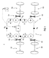
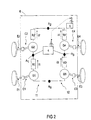
- FIGS. 1 and 2 each present an exemplary embodiment of a detection device according to the invention which differ from each other only in that each electric generator is coupled to an axle of the vehicle in Figure 1 , and to an axis of rotation of a wheel of said vehicle in Figure 2 .
- the electric generators G 1 , G 2 , G 3 , G 4 shown in FIG. Figure 2 are each coupled by a coupling means C1, C2, C3, C4, for example belt or gear or cardan, to an axis of rotation E1, E2, E3, E4 of a wheel of the vehicle 6, each being thus coupled to a different axis of rotation and independent of other axes of rotation, said vehicle comprising in particular said control station 5 capable of receiving a signal from said voltage meter 4.
- each wheel or axle of the vehicle 6 drives a different electric generator G 1 , G 2 , G 3, G 4 , in particular by a direct (eg cardan) or indirect (eg belt) coupling.
- G j 1,, 2n
- the electric generators G 1 ,, G n respectively belonging to the sections T 1 , T n of the first branch
- the electric generators G n + 1 , G 2n respectively belonging to the sections T 1 ,, T n of the second branch.
- R j Through each resistor R j circulates a current, noted i1, i2, i3, i4 in the case of Figures 1 and 2 .
- the voltage meter 4 is therefore able to detect a potential difference called U A1, A3 between the connection points A 1 and A 3 .
- FIG. 2 applies in particular to a metro vehicle provided for example with four pneumatic wheels each towed by an electric motor.
- the present invention may advantageously be applied to other types of vehicles such as an iron wheel train by allowing a control of the rotation speed of the axles, or to a truck, but also to a car metro or train not towed.
- Vj proportional to the speed of rotation of said wheel
- V1, V2, V3 and V4 represent the voltages generated by each generator.
- the wheels of the vehicle having a confused axis of rotation are respectively coupled to an electric generator G k belonging to the first branch and to an electric generator G k + n belonging to the second branch, with k ⁇ ⁇ 1,, n ⁇ .
- the electric generator G k can precede the resistance R k , respectively R k + n , or vice versa.
- the independent rotational drives of right and left wheels having a coinciding axis of rotation are intended to be coupled respectively to the electric generator G k and G k + n belonging to the sections T k of the first and second branches, respectively.
- one of these wheels breaks the rotational speed of the other wheels and rotates at a speed different from the other wheels, then an imbalance is created in the branches of the electric circuit according to the invention, and the voltage U A1, A3 ceases. to be null.
- the voltage meter 4 is capable of detecting whether the voltage U A1, A3 is non-zero and is suitable, for example, for triggering an alarm system or for opening a safety loop that would warn an operator at the control station, or to transmit a warning signal to a central control system or automation system of said vehicle as soon as the voltage U A1, A3 differs from the zero value.
- the threshold value according to the invention is in this particular case a zero voltage value, and the voltage meter is capable of detecting whether the voltage U A1, A3 differs from this threshold value or not.
- the Figure 3 describes another particular embodiment of the invention advantageously to avoid false detection of rotation speed difference of certain wheels when said vehicle approaches a curvilinear trajectory. Indeed, when said vehicle approaches a curve, the rotation speed difference between the outer wheels and the inner wheels of the curve is likely to trigger a false alarm. This is indeed a "false” alert because this difference in rotational speed is simply due to the curvilinear trajectory and not a displacement with friction of one of the wheels. On the other hand, when the vehicle is registered in a curve of constant radius, although the outer wheels of the vehicle turn faster than the inner wheels, the particular embodiment presented in FIG.
- crossings could also be made, for example on the left, so that one would have successively: A 0 , G 2 , R 2 , A 1 , G 1 , R 1 , A 2 , R 4 , G 4 , A 3 , R 3 , and G 3 , then return to A 0 , or else, between right front and left rear or vice versa.
- the Figures 2 and 3 show examples of embodiment of the device according to the invention for typical cases of vehicles comprising 4 independent wheels.
- the detection device according to the invention can also be used for vehicles with 4 or more wheels or axles.
- several electrical circuits of the device according to the invention may preferentially be connected in series in order to detect a possible friction of a wheel on a track, when said vehicle comprises 6, 8, or 10 axles or wheels.
- the detection device according to the invention is in particular characterized in that it may comprise a first friction detection device as previously described coupled in series with a second similar detection device.
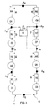
- the Figure 4 finally shows a detection device according to the invention for equipping a vehicle comprising 8 wheels or iron axles.
- each of the 8 wheels is coupled to an electric generator G 1 , ..., G 8 by a coupling means, for example a cardan able to couple an axis of rotation of the wheel to said electric generator G 1 ,. .., G 8 .
- a coupling means for example a cardan able to couple an axis of rotation of the wheel to said electric generator G 1 ,. .., G 8 .
- Each of these electric generators produces a voltage proportional to the speed of rotation of the wheel. Therefore, each electrical resistance R 1 , ..., R 8 is traversed by an electric current i1, ..., i8.
- the coupling of each electric generator to a rotatable element by the rotation of at least one wheel of the vehicle is preferably made so that a difference in rotational speed of one of said wheels of the vehicle does not cause a false detection by the tension meter of a friction of one of said wheels.
- the crossings mentioned above are applicable mutatis mutandis to the electrical circuit of the Figure 4 .
- the voltage meter 4 is in particular able to measure the voltage U A7, A3 between the connection points A 7 and A 3 .
- the threshold value would be zero. Nevertheless, it could also measure the voltage U A6, A3 between the connection points A 6 and A 3 , the threshold value being therefore equal to U A7, A6 .
- the present invention also relates to a vehicle comprising the detection device described above and for which each of said electric generators is coupled by means of said coupling means to a rotable element by rotation of at least one wheel of the vehicle, by example, each electric generator being coupled to a different axle or wheel of said vehicle.
Landscapes
- Engineering & Computer Science (AREA)
- Transportation (AREA)
- Mechanical Engineering (AREA)
- Electric Propulsion And Braking For Vehicles (AREA)
Priority Applications (3)
| Application Number | Priority Date | Filing Date | Title |
|---|---|---|---|
| EP12290320.6A EP2712760A1 (de) | 2012-09-27 | 2012-09-27 | Vorrichtung und Methode zur Erfassung des Reifenabriebs auf der Fahrbahn |
| PCT/EP2013/065493 WO2014048604A1 (fr) | 2012-09-27 | 2013-07-23 | Dispositif et méthode de détection de frottement roue-piste |
| TW102133577A TW201418066A (zh) | 2012-09-27 | 2013-09-17 | 用於偵測輪-軌摩擦的裝置及方法 |
Applications Claiming Priority (1)
| Application Number | Priority Date | Filing Date | Title |
|---|---|---|---|
| EP12290320.6A EP2712760A1 (de) | 2012-09-27 | 2012-09-27 | Vorrichtung und Methode zur Erfassung des Reifenabriebs auf der Fahrbahn |
Publications (1)
| Publication Number | Publication Date |
|---|---|
| EP2712760A1 true EP2712760A1 (de) | 2014-04-02 |
Family
ID=47088768
Family Applications (1)
| Application Number | Title | Priority Date | Filing Date |
|---|---|---|---|
| EP12290320.6A Withdrawn EP2712760A1 (de) | 2012-09-27 | 2012-09-27 | Vorrichtung und Methode zur Erfassung des Reifenabriebs auf der Fahrbahn |
Country Status (3)
| Country | Link |
|---|---|
| EP (1) | EP2712760A1 (de) |
| TW (1) | TW201418066A (de) |
| WO (1) | WO2014048604A1 (de) |
Families Citing this family (1)
| Publication number | Priority date | Publication date | Assignee | Title |
|---|---|---|---|---|
| DE112015001924B4 (de) | 2014-04-22 | 2021-07-01 | Mitsubishi Electric Corporation | Motorsteuereinrichtung |
Citations (8)
| Publication number | Priority date | Publication date | Assignee | Title |
|---|---|---|---|---|
| US2735090A (en) | 1956-02-14 | maenpaa | ||
| US3663875A (en) * | 1969-01-30 | 1972-05-16 | Mitsubishi Electric Corp | Control system for electric vehicles |
| US3764867A (en) * | 1972-11-14 | 1973-10-09 | Gen Electric | Traction motor speed regulation for propulsion systems providing smooth stepless changes in speed and automatic wheel slip control |
| US4071282A (en) | 1976-02-04 | 1978-01-31 | Vapor Corporation | Slip-slide detector system for railway car wheels |
| US4463289A (en) | 1982-03-11 | 1984-07-31 | General Electric Company | Wheel slip control using differential signal |
| US20040130618A1 (en) | 2001-05-28 | 2004-07-08 | Kilian Krzysztof Piotr | Automated wheel slide detector |
| US20060180760A1 (en) | 2005-02-14 | 2006-08-17 | Spirit Solutions Inc. | Smart thermal imaging and inspection device for wheels and components thereof and method |
| US20080211434A1 (en) | 2007-03-01 | 2008-09-04 | Wolfgang Daum | System, Method and Computer Readable Media for Reducing Wheel Sliding on a Locomotive |
-
2012
- 2012-09-27 EP EP12290320.6A patent/EP2712760A1/de not_active Withdrawn
-
2013
- 2013-07-23 WO PCT/EP2013/065493 patent/WO2014048604A1/fr not_active Ceased
- 2013-09-17 TW TW102133577A patent/TW201418066A/zh unknown
Patent Citations (8)
| Publication number | Priority date | Publication date | Assignee | Title |
|---|---|---|---|---|
| US2735090A (en) | 1956-02-14 | maenpaa | ||
| US3663875A (en) * | 1969-01-30 | 1972-05-16 | Mitsubishi Electric Corp | Control system for electric vehicles |
| US3764867A (en) * | 1972-11-14 | 1973-10-09 | Gen Electric | Traction motor speed regulation for propulsion systems providing smooth stepless changes in speed and automatic wheel slip control |
| US4071282A (en) | 1976-02-04 | 1978-01-31 | Vapor Corporation | Slip-slide detector system for railway car wheels |
| US4463289A (en) | 1982-03-11 | 1984-07-31 | General Electric Company | Wheel slip control using differential signal |
| US20040130618A1 (en) | 2001-05-28 | 2004-07-08 | Kilian Krzysztof Piotr | Automated wheel slide detector |
| US20060180760A1 (en) | 2005-02-14 | 2006-08-17 | Spirit Solutions Inc. | Smart thermal imaging and inspection device for wheels and components thereof and method |
| US20080211434A1 (en) | 2007-03-01 | 2008-09-04 | Wolfgang Daum | System, Method and Computer Readable Media for Reducing Wheel Sliding on a Locomotive |
Also Published As
| Publication number | Publication date |
|---|---|
| TW201418066A (zh) | 2014-05-16 |
| WO2014048604A1 (fr) | 2014-04-03 |
Similar Documents
| Publication | Publication Date | Title |
|---|---|---|
| EP2217476B1 (de) | System zur steuerung eines fahrzeugs mit bestimmung der relativen geschwindigkeit zum boden | |
| EP2891590B1 (de) | Gelenktes Landfahrzeug, das eine Steuerungsvorrichtung beim Entgleisen des Fahrzeugs umfasst, und entsprechendes Steuerungsverfahren der Entgleisung | |
| EP0982176B1 (de) | Stromversorgungssystem für ein elektrisch angetriebenes Fahrzeug | |
| EP2771219B1 (de) | System zur dynamischen steuerung des rollens der führungsrolle(n) für eine anordnung zum führen eines fahrzeugs entlang von mindestens einer schiene | |
| CA2378636C (fr) | Procede et dispositif de pilotage de l'alimentation en energie electrique d'un vehicule a traction electrique destine a fonctionner en mode d'alimentation externe ou en mode d'alimentation autonome | |
| FR3092811A1 (fr) | Procede et systeme de pilotage d’un essieu electrique d’une remorque ou semi-remorque | |
| FR3037195A1 (fr) | Ensemble constitue d'un vehicule electrique et d'un systeme de recharge stationnaire par conduction ; systeme, installation, vehicule et procede associes | |
| FR3032397A1 (fr) | Systeme de protection de la chaine de traction d'un vehicule ferroviaire, ligne de transmission et vehicule ferroviaire associes | |
| EP2923915A1 (de) | Ausrüstung für ein sekundärerfassungssystem auf dem gleis, und signalisierungssystem, das eine solche ausrüstung enthält | |
| EP2712760A1 (de) | Vorrichtung und Methode zur Erfassung des Reifenabriebs auf der Fahrbahn | |
| EP0054453A1 (de) | Vorrichtung zum Feststellen des Unterdruckes eines Flugzeuglandegestellreifens | |
| EP0208598B1 (de) | Schienengeführtes Fahrzeug mit Schwenkbaren Radachsen | |
| EP2682321B1 (de) | Diagnosesystem des Strukturzustands von Rollvorrichtungen eines Geräts, einschließlich integrierter Berechnungs- und Analysemittel, die strukturell vom Gerät getrennt sind | |
| FR2926511A1 (fr) | Systeme de freinage automatique d'un vehicule | |
| EP2682322A1 (de) | Diagnosesystem des Strukturzustands von Rollvorrichtungen eines Geräts, das an Bord des Geräts integrierte Berechnungs- und Analysemittel umfasst | |
| FR3075144A1 (fr) | Vehicule ferroviaire, systeme ferroviaire et procede de composition de vehicule ferroviaire associes | |
| FR2875906A1 (fr) | Dispositif de controle prenant en compte les quatre roues en rotation d'un vehicule, sa voie et son empattement | |
| FR3062101A1 (fr) | Procede pour faire fonctionner un vehicule hybride, notamment automobile | |
| EP2314491B1 (de) | Vorrichtung zur Überwachung der Drehbewegung eines Drehorgans zum Abstützen und Lenken in einer Skilift-Anlage | |
| CA1062357A (fr) | Procede de controle continu de vitesse pour vehicule moteur et equipement pour la mise en oeuvre de ce procede | |
| EP3309036B1 (de) | Steuervorrichtung für ein schienenfahrzeug, und schienenfahrzeug, das eine solche steuervorrichtung umfasst | |
| FR2935640A1 (fr) | Procede de supervision d'un systeme antiroulis actif permettant l'activation du systeme des le demarrage du moteur et surete de fonctionnement associee et systeme associe | |
| EP2870046B1 (de) | Diagnose des strukturellen zustands eines rotierenden bewegungselements einer reihe rotierender elemente von einer vorrichtung, einer maschine oder einem fahrzeug, insbesondere eines fahrzeugs mit rädern | |
| FR3150495A1 (fr) | Dispositif d’entrainement de véhicule, notamment pour un véhicule ferroviaire | |
| FR2897326A1 (fr) | Procede et dispositif pour l'optimisation de l'agencement des elements constitutifs de trains dits de "travaux" |
Legal Events
| Date | Code | Title | Description |
|---|---|---|---|
| PUAI | Public reference made under article 153(3) epc to a published international application that has entered the european phase |
Free format text: ORIGINAL CODE: 0009012 |
|
| AK | Designated contracting states |
Kind code of ref document: A1 Designated state(s): AL AT BE BG CH CY CZ DE DK EE ES FI FR GB GR HR HU IE IS IT LI LT LU LV MC MK MT NL NO PL PT RO RS SE SI SK SM TR |
|
| AX | Request for extension of the european patent |
Extension state: BA ME |
|
| RAP1 | Party data changed (applicant data changed or rights of an application transferred) |
Owner name: SIEMENS S.A.S. |
|
| 17P | Request for examination filed |
Effective date: 20140919 |
|
| RBV | Designated contracting states (corrected) |
Designated state(s): AL AT BE BG CH CY CZ DE DK EE ES FI FR GB GR HR HU IE IS IT LI LT LU LV MC MK MT NL NO PL PT RO RS SE SI SK SM TR |
|
| RIC1 | Information provided on ipc code assigned before grant |
Ipc: B60T 8/17 20060101ALI20141031BHEP Ipc: B60L 3/10 20060101AFI20141031BHEP Ipc: B60T 8/172 20060101ALI20141031BHEP Ipc: H02P 5/685 20060101ALI20141031BHEP |
|
| GRAP | Despatch of communication of intention to grant a patent |
Free format text: ORIGINAL CODE: EPIDOSNIGR1 |
|
| INTG | Intention to grant announced |
Effective date: 20141216 |
|
| STAA | Information on the status of an ep patent application or granted ep patent |
Free format text: STATUS: THE APPLICATION IS DEEMED TO BE WITHDRAWN |
|
| 18D | Application deemed to be withdrawn |
Effective date: 20150429 |