EP2712840B1 - Véhicule mobile de type à chenilles - Google Patents
Véhicule mobile de type à chenilles Download PDFInfo
- Publication number
- EP2712840B1 EP2712840B1 EP13183981.3A EP13183981A EP2712840B1 EP 2712840 B1 EP2712840 B1 EP 2712840B1 EP 13183981 A EP13183981 A EP 13183981A EP 2712840 B1 EP2712840 B1 EP 2712840B1
- Authority
- EP
- European Patent Office
- Prior art keywords
- travel
- crawler
- travelling
- transversely opposite
- velocity
- Prior art date
- Legal status (The legal status is an assumption and is not a legal conclusion. Google has not performed a legal analysis and makes no representation as to the accuracy of the status listed.)
- Not-in-force
Links
Images



Classifications
-
- B—PERFORMING OPERATIONS; TRANSPORTING
- B62—LAND VEHICLES FOR TRAVELLING OTHERWISE THAN ON RAILS
- B62D—MOTOR VEHICLES; TRAILERS
- B62D11/00—Steering non-deflectable wheels; Steering endless tracks or the like
- B62D11/02—Steering non-deflectable wheels; Steering endless tracks or the like by differentially driving ground-engaging elements on opposite vehicle sides
- B62D11/04—Steering non-deflectable wheels; Steering endless tracks or the like by differentially driving ground-engaging elements on opposite vehicle sides by means of separate power sources
-
- B—PERFORMING OPERATIONS; TRANSPORTING
- B66—HOISTING; LIFTING; HAULING
- B66F—HOISTING, LIFTING, HAULING OR PUSHING, NOT OTHERWISE PROVIDED FOR, e.g. DEVICES WHICH APPLY A LIFTING OR PUSHING FORCE DIRECTLY TO THE SURFACE OF A LOAD
- B66F11/00—Lifting devices specially adapted for particular uses not otherwise provided for
- B66F11/04—Lifting devices specially adapted for particular uses not otherwise provided for for movable platforms or cabins, e.g. on vehicles, permitting workmen to place themselves in any desired position for carrying out required operations
- B66F11/044—Working platforms suspended from booms
- B66F11/046—Working platforms suspended from booms of the telescoping type
-
- B—PERFORMING OPERATIONS; TRANSPORTING
- B66—HOISTING; LIFTING; HAULING
- B66C—CRANES; LOAD-ENGAGING ELEMENTS OR DEVICES FOR CRANES, CAPSTANS, WINCHES, OR TACKLES
- B66C9/00—Travelling gear incorporated in or fitted to trolleys or cranes
- B66C9/10—Undercarriages or bogies, e.g. end carriages, end bogies
-
- B—PERFORMING OPERATIONS; TRANSPORTING
- B66—HOISTING; LIFTING; HAULING
- B66F—HOISTING, LIFTING, HAULING OR PUSHING, NOT OTHERWISE PROVIDED FOR, e.g. DEVICES WHICH APPLY A LIFTING OR PUSHING FORCE DIRECTLY TO THE SURFACE OF A LOAD
- B66F17/00—Safety devices, e.g. for limiting or indicating lifting force
- B66F17/006—Safety devices, e.g. for limiting or indicating lifting force for working platforms
Definitions
- the present invention relates to a crawler-type travelling vehicle capable of travelling by means of crawler travel devices provided on transversely opposite sides of a vehicle body.
- crawler travel device' is to be understood to incorporate devices otherwise known as 'caterpillars' or 'tracks'.
- a known one of such crawler-type travelling vehicles is designed to be capable of a forward and backward straight travel, a slalom turn, a pivot turn and a spin turn by controlling the revolving directions and velocities of the transversely opposite crawler travel devices in accordance with the directions and amounts of operation on transversely opposite two travel operation levers (see Japanese Laid-Open Patent Publication No. 2003-343510(A ) for example).
- Another known crawler-type travelling vehicle includes, instead of the transversely opposite two travel operation levers, a travel operation device having a travel lever for switching between a forward travel and a backward travel, an accelerator pedal for setting a travelling velocity, and a steering wheel for setting a turning direction and a turning amount (see Japanese Laid-Open Utility Model Publication No. H5-24481(A ) for example).
- a travel operation device having a travel lever for switching between a forward travel and a backward travel, an accelerator pedal for setting a travelling velocity, and a steering wheel for setting a turning direction and a turning amount
- a joystick-type travel operation device which is capable of setting a forward travel, a backward travel, a travelling velocity, a turning direction and a turning amount by means of a single travel operation lever (see Japanese Laid-Open Patent Publication No. 2002-104227(A ) for example).
- the conventional crawler-type travelling vehicle as disclosed in JP-2003 048692 which discloses the preamble of claim 1, is configured to perform a drive control over the transversely opposite crawler travel devices such that when the travel operation device is operated to cause a turn, the turn set by the travel operation device is realized by decelerating only that crawler travel device which is positioned inwardly relative to the other in the turning direction.
- Such a turn control has a problem that when the travel operation device is operated to cause a turn during a straight travel for example, an excessive inertial force (centrifugal force) is sometimes exerted on the vehicle and rider in accordance with the current travelling velocity and the amount of a turning operation and, hence, the travelling stability of the vehicle and the ride quality felt by the rider are unfavourable in such cases.
- an excessive inertial force centrifugal force
- An object of the present invention is to provide a crawler-type travelling vehicle which is capable of improving the travelling stability of the vehicle during turning and the ride quality felt by the rider during turning.
- a crawler-type travelling vehicle includes: a vehicle body ; transversely opposite crawler travel devices provided on transversely opposite sides of the vehicle body; transversely opposite travel motors which respectively drive the transversely opposite crawler travel devices; a travel operation device which sets a travelling direction, a travelling velocity (speed), a turning direction and a turning amount in accordance with a direction and an amount of operation thereon; and a travel control device which controls a direction and a velocity of revolution of each of the transversely opposite travel motors in accordance with the travelling direction, the travelling velocity, the turning direction and the turning amount set by the travel operation device.
- the travel control device When the travel operation device is operated to cause a straight travel, the travel control device performs a control such that the transversely opposite travel motors are caused to revolve for realizing the straight travel in a direction and at a velocity corresponding to the direction and the amount of operation on the travel operation device.
- the travel control device When the travel operation device is operated to cause a turn, the travel control device performs a control such that the transversely opposite travel motors are caused to revolve for realizing the turn set by the travel operation device by decelerating the travelling velocities of the transversely opposite crawler travel devices from travelling velocities of the transversely opposite crawler travel devices travelling straight by equal values of velocity corresponding to the turning amount set by the travel operation device and further decelerating the travelling velocity of the crawler travel device which is positioned inwardly relative to the other crawler travel device in the turning direction, further comprising a lifting device which is mounted on the vehicle body and which moves a workbench up and down at least; and workbench position detecting means which detects a position of the workbench relative to the vehicle body, when the travel operation device is operated to cause the turn, the travel control device performs a control such that amounts of deceleration of the travelling velocities of the transversely opposite crawler travel devices from the travelling velocity of the straight travel become larger in accordance
- the travel control device performs a control such that the transversely opposite travel motors are caused to revolve for realizing the straight travel at a lower velocity than the travelling velocity corresponding to the amount of operation on the travel operation device in accordance with a vertical distance between the workbench and the vehicle body detected by the workbench position detecting means.
- the lifting device includes a boom mounted on the vehicle body and capable of derricking (swinging upwardly and downwardly), telescoping (extending and contracting), and rotating and which moves up and down a workbench attached to a distal end portion of the boom; and workbench position detecting means (including for example a derricking angle detector 81 and a length detector 82 according to the embodiment) which detects a position of the workbench relative to the vehicle body, wherein when the travel operation device is operated to cause the turn, the travel control device performs a control such that amounts of deceleration of the travelling velocities of the transversely opposite crawler travel devices from the travelling velocity of the straight travel become larger in accordance with a horizontal distance between the workbench and the vehicle body detected by the workbench position detecting means.
- workbench position detecting means including for example a derricking angle detector 81 and a length detector 82 according to the embodiment
- the transversely opposite travel motors are electric motors which respectively drive the transversely opposite crawler travel devices when supplied with electric power, wherein the transversely opposite electric travel motors have the function of generating electric power when driven to revolve; and when the turn is performed under the revolution control over the transversely opposite electric motors for realizing the turn set by the travel operation device, the driving force that is produced when that crawler travel device which is positioned inwardly relative to the other crawler travel device in the turning direction is driven by that crawler travel device which is positioned outwardly relative to the other crawler travel device in the turning direction is utilized to generate electric power by that electric travel motor which drives the inwardly positioned crawler travel device.
- the electric power thus generated produces a braking force in the associated electric travel motor, thereby inhibiting the number of revolutions of the inwardly positioned electric travel motor from rising. For this reason, a turn at a predetermined target rudder angle can be realized. Further, the electric power thus generated can charge the battery supplying electric power to the electric travel motors, thereby prolonging the serviceable life of the battery and realizing energy saving.
- FIG. 1 illustrates a crawler-type high place work vehicle 1 as one example of the crawler-type travelling vehicle according to the present invention.
- the crawler-type high place work vehicle 1 includes a crawler travel member 10, a rotating structure 20 rotatably mounted on an upper portion of the crawler travel member 10, and a boom 30 derrickably mounted on an upper portion of the rotating structure 20.
- the crawler travel member 10 includes transversely opposite crawler travel devices 12a and 12b (see FIG. 3 ) provided on transversely opposite sides of a travel member frame 11.
- the transversely opposite crawler travel devices 12a and 12b each includes a driver wheel 13 attached to a rear portion of the travel member frame 11, an idler wheel 14 attached to a front portion of the travel member frame 11, a plurality of lower rollers 15 disposed between the driver wheel 13 and the idler wheel 14, a single upper roller 16 disposed between the driver wheel 13 and the idler wheel 14, and a crawler belt 17 entrained about the driver wheel 13, idler wheel 14, lower rollers 15 and upper roller 16.
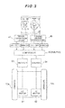
- the transversely opposite driver wheels 13 are each driven to rotate by transmission of output power of a respective one of transversely opposite travel motors 51 and 52 (see FIG. 3 ) disposed on the travel member frame 11 through a reduction gear (not shown). As shown in FIG. 2 , the transversely opposite travel motors 51 and 52 drive the transversely opposite driver wheels 13 by being driven to revolve by electric power supplied from a battery 90 located inside the rotating structure 20 through respective transversely opposite inverters 53 and 54 for travel. The transversely opposite travel motors 51 and 52 have the function of generating electric power when driven to revolve by the transversely opposite driver wheels 13. The revolving directions and velocities of the transversely opposite motors 51 and 52 are controlled in accordance with the directions and amounts of operation on a travel operation lever 47 and a turning amount operation dial 48 which are provided inside an operating box 42 to be described later.
- the rotating structure 20 is configured to be capable of rotating within a 360 degree range in a horizontal plane relative to the crawler travel member 10 by causing a rotation motor 21 provided inside the rotating structure 20 to revolve.
- the boom 30 is derrickably mounted on the upper portion of the rotating structure 20 by means of a foot pin 23.
- the boom 30 includes a proximal boom 30a derrickably mounted on the rotating structure 20 by means of the foot pin 23, an intermediate boom 30b and a distal boom 30c which are telescopically combined together.
- the boom 30 is designed to be capable of wholly telescoping in the longitudinal direction by actuating a telescoping cylinder 31 provided therein.
- the boom 30 is also designed to be capable of derricking in a vertical plane by expanding and retracting a derrick cylinder 22 spanning between the proximal boom 30a and the rotating structure 20.
- a vertical post 32 has a lower end portion attached to a distal end portion of the distal boom 30c by means of a pivot pin.
- the vertical post 32 is designed to be constantly held in a vertical position irrespective of the derricking angle of the boom 30 by means of a levelling device (not shown) provided inside the boom 30.
- a workbench (or a working platform) 40 is fitted on an upper portion of the vertical post 32 by means of a workbench retainer bracket (not shown) so as to be swingable in a horizontal plane.
- the workbench retainer bracket is provided therein with a swing motor 41 which can swing the workbench 40 about the vertical post 32 when actuated to revolve. Since the vertical post 32 is constantly held in the vertical position as described above, the floor surface of the workbench 40 is constantly held in a horizontal position irrespective of the derricking angle of the boom 30.
- the derrick cylinder 22, telescoping cylinder 31, rotation motor 21 and swing motor 41 are driven to actuate the boom 30, rotating structure 20 and workbench 40 when hydraulic fluid delivered from a hydraulic pump 70 provided inside the rotating structure 20 is supplied thereto through control valves 71 to 74 respectively associated with the cylinders 22 and 31 and motors 21 and 41.
- the hydraulic pump 70 is driven by a pump driving motor 75.
- the pump driving motor 75 is driven to revolve by electric power supplied thereto from the battery 90 through a boom actuating inverter 76.
- the actuating directions and velocities of the derrick cylinder 22, telescoping cylinder 31, rotation motor 21 and swing motor 41 are controlled in accordance with the directions and amounts of operation on operation levers 43 to 46 provided inside an operating box 42 to be described later.
- the workbench 40 is provided thereon with the operating box 42 having a variety of operation means.
- the operating box 42 is provided with the derrick operation lever 43 for derricking the boom 30, telescoping operation lever 44 for telescoping the boom 30, rotation operation lever 45 for rotating the rotating structure 20, and swing operation lever 46 for swinging the workbench 40.
- Each of the operation levers 43 to 46 can be operated to lean forwardly and backwardly from a neutral position which is a vertical position and is configured to return to the neutral position automatically by means of a built-in spring when the operation lever in a leant position is freed from the operator's hand.
- the boom operation control section 60a controls the amounts of hydraulic fluid to be supplied from the hydraulic pump 70 to the cylinders 22 and 31 and motors 21 and 41 by electromagnetically driving the spools of the control valves 71 to 74 correspondingly to the directions and amounts according to the boom operation signals inputted, thereby controlling the directions and amounts of operations of the cylinders 22 and 31 and motors 21 and 41.
- the boom operation control section 60a also controls electric power to be supplied from the battery 90 to the pump driving motor 75 through the boom actuating inverter 76 in accordance with the boom operation signals inputted, thereby controlling the amounts of hydraulic fluid to be delivered from the hydraulic pump 70. Therefore, an operator M on the workbench 40 operates the operation levers 43 to 46 to derrick and telescope the boom 30, rotate the rotating structure 20 in the horizontal plane and swing the workbench 40, thereby making it possible to move the workbench 40 to a desired high place.
- each of the boom operation signals outputted by operating the operation levers 43 to 46 is substantially proportional to the amount of operation on the associated operation lever and, hence, the operating velocities of the cylinders 22 and 31 and motors 21 and 41 can be adjusted by adjusting the amounts of operation on the operation levers 43 to 46.
- Such operation levers 43 to 46 are also provided on the rotating structure 20 and, hence, an operator on the rotating structure 20 can also actuate the boom 30, rotating structure 20 and workbench 40.
- the operating box 42 is provided with the travel operation lever 47 and turning amount operation dial 48 for travel operation over the transversely opposite crawler travel devices 12a and 12b.
- the travel operation lever 47 can be operated to lean forwardly and backwardly from a neutral position which is a vertical position and is configured to return to the neutral position automatically by means of a built-in spring when the travel operation lever 47 in a leant position is freed from the operator's hand.
- voltage signals corresponding to the operating direction (leaning direction) and operating amount (leaning amount) relative to the neutral position serving as a datum are outputted and then inputted as travel command signals to a travel control section 60b of the controller 60.
- the operation to lean the travel operation lever 47 forwardly from the neutral position corresponds to a forward travel command for the transversely opposite crawler travel devices 12a and 12b.
- a larger value is set as a target travelling velocity of forward travel by the travel control section 60b.
- the operation to lean the travel operation lever 47 backwardly from the neutral position corresponds to a backward travel command for the transversely opposite crawler travel devices 12a and 12b.
- a larger value is set as a target travelling velocity of backward travel by the travel control section 60b.
- the operation to return the travel operation lever 47 to the neutral position corresponds to a stop command for the transversely opposite crawler travel devices 12a and 12b.
- the turning amount operation dial 48 can be operated to turn rightwardly and leftwardly from the neutral position (the position shown in FIG. 3 ) and is configured to return to the neutral position automatically by means of a built-in spring when the turning amount operation dial 48 in a turned position is freed from the operator's hand.
- voltage signals corresponding to the operating direction (turning direction) and operating amount (turning amount) relative to the neutral position serving as a datum are outputted and then inputted as turning amount command signals to the travel control section 60b.
- the operation to turn the turning amount operation dial 48 rightwardly from the neutral position corresponds to a rightward turn command for the transversely opposite crawler travel devices 12a and 12b.
- a larger value is set as a target rightward turning amount by the travel control section 60b.
- the operation to turn the turning amount operation dial 48 leftwardly from the neutral position corresponds to a leftward turn command for the transversely opposite crawler travel devices 12a and 12b.
- a larger value is set as a target leftward turning amount by the travel control section 60b.
- the operation to return the turning amount operation dial 48 to the neutral position corresponds to a command to zero the turning amount for the transversely opposite crawler travel devices 12a and 12b (straight travel command).
- the travel control section 60b of the controller 60 sets a target straight travelling velocity of the transversely opposite crawler travel devices 12a and 12b according to the travel command signals and controls the revolution velocities of the transversely opposite travel motors 51 and 52 by controlling electric power to be supplied to the transversely opposite travel motors 51 and 52 such that the travelling velocities of both of the transversely opposite crawler travel devices 12a and 12b follow the target straight travelling velocity.
- the travel control section 60b sets target turning velocities of the respective transversely opposite crawler travel devices 12a and 12b according to the turning amount command signals, and then controls the revolution velocities of the transversely opposite travel motors 51 and 52 by controlling electric power to be supplied to the transversely opposite travel motors 51 and 52 such that the travelling velocities of the transversely opposite crawler travel devices 12a and 12b follow their respective target turning velocities.
- the revolution velocities of the transversely opposite travel motors 51 and 52 are controlled such that the transversely opposite crawler travel devices 12a and 12b are caused to turn according to the turning amount command signals, which are made by decelerating the travelling velocities of the transversely opposite crawler travel devices 12a and 12b from the target straight travelling velocity set by the travel operation lever 47 by equal values of velocity which are predetermined in accordance with the turning amount command signals inputted from the turning amount operation dial 48, the turning amount command signals being further made by decelerating the travelling velocity of one of the crawler travel device 12a and 12b which is positioned inwardly relative to the other in the turning direction.
- the turning amount command signals which are made by decelerating the travelling velocities of the transversely opposite crawler travel devices 12a and 12b from the target straight travelling velocity set by the travel operation lever 47 by equal values of velocity which are predetermined in accordance with the turning amount command signals inputted from the turning amount operation dial 48, the turning amount command signals being further made by decelerating the
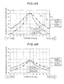
- FIG. 4A illustrates a case where the travel operation lever 47 is operated to lean forwardly from the neutral position by an operating amount of 100% (maximum).
- the amount of turning operation on the turning amount operation dial 48 is 0 degrees (neutral position)
- the revolution velocities of the transversely travel motors 51 and 52 are controlled to cause the travelling velocities of both of the transversely opposite crawler travel devices 12a and 12b to follow the target straight travelling velocity V x 100%, thereby causing the crawler travel member 10 to travel forwardly.
- the turning amount operation dial 48 When the turning amount operation dial 48 is turned rightwardly by 30 degrees for example from the neutral position during straight travel of the crawler travel member 10 (i.e., transversely opposite crawler travel devices 12a and 12b) at the travelling velocity V x 100%, the left-hand crawler travel device 12a which is positioned outwardly relative to the other in the turning direction is decelerated by ⁇ V 1 , while the right-hand crawler travel device 12b which is positioned inwardly relative to the other in the turning direction is decelerated by ⁇ V 1 + ⁇ V 2 .
- the revolution velocity of the left-hand travel motor 51 is controlled to cause the travelling velocity of the outwardly positioned left-hand crawler travel device 12a to follow the target turning velocity V x 100% -V 1
- the revolution velocity of the right-hand travel motor 52 is controlled to cause the travelling velocity of the inwardly positioned right-hand crawler travel device 12b to follow the target turning velocity V x 100% -( ⁇ V 1 + ⁇ V 2 ).
- the crawler travel member 10 is caused to turn rightwardly (in a slalom turn fashion) correspondingly to the amount of 30 degrees of turning operation on the turning amount operation dial 48.
- both of the crawler travel devices 12a and 12b are decelerated by ⁇ V 1 to improve the turning stability, while the inwardly positioned right-hand crawler travel device 12b is further decelerated from the thus decelerated velocity by ⁇ V 2 to realize the turn corresponding to the amount of operation on the turning amount operation dial 48.
- the revolution velocity of the left-hand travel motor 51 is controlled to cause the travelling velocity of the left-hand crawler travel device 12a positioned outwardly relative to the other to follow a target turning velocity V x 100% - ⁇ V 3 ( ⁇ V 3 > ⁇ V 1 ), while the right-hand travel motor 52 is controlled to cause the right-hand crawler travel device 12b positioned inwardly relative to the other to stop.
- the crawler travel member 10 is caused to turn rightwardly in a pivot turn fashion (turn about the centre of the right-hand crawler travel device 12b serving as the centre of turning).
- the revolution velocity of the left-hand travel motor 51 is controlled to cause the travelling velocity of the left-hand crawler travel device 12a positioned outwardly relative to the other to follow a target turning velocity V x 100% - ⁇ V 4 ( ⁇ V 4 > ⁇ V 3 ), while the right-hand travel motor 52 is controlled to cause the right-hand crawler travel device 12b positioned inwardly relative to the other to turn in the opposite direction at a target turning velocity V x 100% - ⁇ V 4.
- the crawler travel member 10 is caused to turn rightwardly in a spin turn fashion (turn about the centre of the crawler travel member 10 serving as the centre of turning).
- the inwardly positioned right-hand crawler travel device 12b is sometimes driven by the outwardly positioned left-hand crawler travel device 12a. (Such a phenomenon sometimes occurs during a gentle slalom turn.)
- the right-hand travel motor 52 By utilizing the driving force produced at that time, the right-hand travel motor 52 generates electric power which charges the battery 90 through the right-hand inverter 54 for travel.
- a control performed when the turning amount operation dial 48 is turned leftwardly from the neutral position is the same as the travel control described above except that that device of the crawler travel devices 12a and 12b which is positioned inwardly relative to the other in the turning direction and that device of the crawler travel devices 12a and 12b which is positioned outwardly relative to the other in the turning direction are reversed.
- FIG. 4B illustrates a case where the travel operation lever 47 is operated to lean forwardly from the neutral position by an amount of operation of 50%.
- the travel control performed in this case is the same as the travel control described above except that the target values are varied.
- the travel control section 60b of the controller 60 has previously established therein information on target values for turning in accordance with the amounts of operation on the travel operation lever 47.
- the crawler-type high place work vehicle 1 is provided with a derricking angle detector 81 configured to detect the derricking angle of the boom 30 from a horizontal position, a length detector 82 configured to detect the length of the boom 30, and a turning angle detector 83 configured to detect the turning angle of the boom 30 (rotating structure 20).
- a derricking angle detector 81 configured to detect the derricking angle of the boom 30 from a horizontal position
- a length detector 82 configured to detect the length of the boom 30,
- a turning angle detector 83 configured to detect the turning angle of the boom 30 (rotating structure 20).
- Information on the derricking angle, length and turning angle of the boom 30 detected by these detectors 81 to 83 is inputted to a determination section 60c of the controller 60.
- the determination section 60c calculates the position of the workbench 40 relative to the crawler travel member 10 based on the information on the derricking angle, length and turning angle of the boom 30 inputted thereto from the detectors 81 to 83. Subsequently, the determination section 60c determines whether or not the position of the workbench 40 is horizontally separated from the crawler travel member 10 by a distance in excess of a predetermined allowable horizontal distance. When determination is made that the position of the workbench 40 is in excess of the allowable horizontal distance, the determination section 60c outputs a first restrictive signal to the travel control section 60b.
- the travel control section 60b performs a control such that when the turning amount command signals are inputted from the turning amount operation dial 48, the amounts of deceleration of the travelling velocities of the transversely opposite crawler travel devices 12a and 12b from the target straight travelling velocity set by the travel operation lever 47 are made larger than when the first restrictive signal is not inputted (when the position of the workbench 40 is not in excess of the allowable horizontal distance), thereby causing the crawler travel member 10 to turn.
- the travel control section 60b may be configured to perform a control such that when the turning amount command signals are inputted from the turning amount operation dial 48, the amounts of deceleration of the travelling velocities of the transversely opposite crawler travel devices 12a and 12b from the target straight travelling velocity set by the travel operation lever 47 become larger in accordance with the horizontal distance between the workbench 40 and the crawler travel member 10 calculated by the determination section 60c (a control for causing the amounts of deceleration to vary linearly in accordance with the horizontal distance).
- the travel control section 60b may be configured to establish a restrictive target velocity which is lower than the target straight travelling velocity corresponding to the amount of operation on the travel operation lever 47 in accordance with the horizontal distance between the workbench 40 and the crawler travel member 10 calculated by the determination section 60c (establish a restrictive target velocity linearly varying with the horizontal direction) when the travel command signals are inputted from the travel operation lever 47 and then perform a control for causing the travelling velocities of the transversely opposite travel motors 51 and 52 to follow the restrictive target velocity thus established.
- FIG. 5 illustrates a case where the travel operation lever 47 is operated to lean forwardly from the neutral position by an amount of operation of 100% (maximum) when the position of the workbench 40 is in excess of the allowable horizontal distance (but not in excess of an allowable vertical distance to be described later).
- the amount of turning operation on the turning amount operation dial 48 is 0 degrees (neutral position)
- the revolution velocities of the transversely opposite travel motors 51 and 52 are controlled to cause the travelling velocities of both of the transversely opposite crawler travel devices 12a and 12b to follow the target straight travelling velocity V x 100%, thereby causing the crawler travel member 10 to travel forwardly.
- a control may be performed such that the travelling velocity of straight travel is set to a smaller value.
- the turning amount operation dial 48 is turned rightwardly by 30 degrees for example from the neutral position during straight travel of the crawler travel member 10 (i.e., transversely opposite crawler travel devices 12a and 12b) at the travelling velocity V x 100%, the travelling velocity of the left-hand crawler travel device 12a which is positioned outwardly relative to the other in the turning direction is decelerated by ⁇ V 5 , while the travelling velocity of the right-hand crawler travel device 12b which is positioned inwardly relative to the other in the turning direction is decelerated by ⁇ V 5 + ⁇ V 6 .
- the revolution velocity of the left-hand travel motor 51 is controlled to cause the travelling velocity of the left-hand crawler travel device 12a positioned outwardly relative to the other to follow the target turning velocity V x 100% - ⁇ V 5
- the revolution velocity of the right-hand travel motor 52 is controlled to cause the travelling velocity of the right-hand crawler travel device 12b positioned inwardly relative to the other to follow the target turning velocity V x 100% ( ⁇ V 5 + ⁇ V 6 ).
- the crawler travel member 10 is caused to turn rightwardly (in a slalom turn fashion) correspondingly to the amount of 30 degrees of turning operation on the turning amount operation dial 48.
- ⁇ V 5 is a larger value than ⁇ V 1 shown in FIG.
- the determination section 60c determines whether or not the position of the workbench 40 is separated upwardly from the crawler travel member 10 by a distance in excess of a predetermined allowable vertical distance (allowable height). When determination is made that the position of the workbench 40 is in excess of the allowable vertical distance, the determination section 60c outputs a second restrictive signal to the travel control section 60b.
- the travel control section 60b In response to input of the second restrictive signal from the determination section 60c, the travel control section 60b establishes a restrictive target velocity which is lower than the target straight travelling velocity according to the travel command signals when the travel command signals are inputted from the travel operation lever 47 and then controls the revolution velocities of the transversely opposite travel motors 51 and 52 to cause the travelling velocities of both of the transversely opposite crawler travel devices 12a and 12b to follow the restrictive target velocity thus established, thereby causing the crawler travel member 10 to travel straight.
- the travel control section 60b may be configured to establish a restrictive target velocity which is lower than the target straight travelling velocity corresponding to the amount of operation on the travel operation lever 47 in accordance with the vertical distance between the workbench 40 and the crawler travel member 10 calculated by the determination section 60c (establish the restrictive target velocity varying linearly with the vertical distance) when the travel command signals are inputted from the travel operation lever 47 and then perform a control for causing the travelling velocities of the transversely opposite travel motors 51 and 52 to follow the restrictive target velocity thus established.
- the travel control section 60b may be configured to perform a control such that when the turning amount command signals are inputted from the turning amount operation dial 48, the amounts of deceleration of the travelling velocity of the transversely opposite crawler travel devices 12a and 12b from the target straight travelling velocity set by the travel operation lever 47 become larger in accordance with the vertical distance between the workbench 40 and the crawler travel member 10 calculated by the determination section 60c (a control for causing the amounts of deceleration to vary linearly with the vertical distance).
- FIG. 6 illustrates a case where the travel operation lever 47 is operated to lean forwardly from the neutral position by an amount of operation of 100% (maximum) when the position of the workbench 40 is in excess of the allowable vertical distance (but not in excess of the allowable horizontal distance).
- the amount of turning operation on the turning amount operation dial 48 is 0 degrees (neutral position)
- the revolution velocities of the transversely opposite travel motors 51 and 52 are controlled to cause the travelling velocities of both of the transversely opposite crawler travel devices 12a and 12b to follow a restrictive target velocity V x about 25% which is lower than the target straight travelling velocity V x 100% according to the travel command signals inputted from the travel operation lever 47, thereby causing the crawler travel member 10 to travel forwardly.
- the revolution velocity of the left-hand travel motor 51 is controlled to cause the travelling velocity of the outwardly positioned left-hand crawler travel device 12a to follow the target turning velocity V x about 25% ⁇ V 7
- the revolution velocity of the right-hand travel motor 52 is controlled to cause the travelling velocity of the inwardly positioned right-hand crawler travel device 12b to follow the target turning velocity V x about 25% ( ⁇ V 7 + ⁇ V 8 ).
- the crawler travel member 10 is caused to turn rightwardly (in a slalom turn fashion) correspondingly to the amount of 30 degrees of turning operation on the turning amount operation dial 48.
- the travel control section 60b When the position of the workbench 40 is in excess of both the allowable horizontal distance and the allowable vertical distance (when both of the first and second restrictive signals are inputted from the determination section 60c), the travel control section 60b performs a control such that the control performed when the position of the workbench 40 is in excess of the allowable horizontal distance is performed, while the control performed when the position of the workbench 40 is in excess of the allowable vertical distance is added as a correction value to the former control. That is, a control is performed such that both of the turning velocity and the straight travelling velocity are set to smaller values than when the position of the workbench 40 is in excess of neither the allowable horizontal distance nor the allowable vertical distance.
- the travel control section 60b is configured to control the revolution velocities of the transversely opposite travel motors 51 and 52 such that when the turning amount command signals are inputted from the turning amount operation dial 48, the transversely opposite crawler travel devices 12a and 12b are caused to turn according to the turning amount command signals by decelerating the transversely opposite crawler travel devices 12a and 12b from the target straight travelling velocity set by the travel operation lever 47 by equal values of velocity which are predetermined according to the turning amount command signals inputted from the turning amount operation dial 48 and further decelerating the travelling velocity of the crawler travel device 12a or 12b which is positioned inwardly relative to the other in the turning direction.
- This configuration can reduce the inertial force (centrifugal force) to be exerted on the vehicle and rider to a small value though the turning velocity is lower than that under the conventional travel control which realizes a turn by decelerating only the inwardly positioned crawler travel device. Therefore, the travelling stability of the vehicle during turning and the ride quality felt by the rider during turning can be improved.
- the travel control section 60b is configured to cause the crawler travel member 10 to turn by performing the control such that when the turning amount command signals are inputted from the turning amount operation dial 48, the amounts of deceleration of the travelling velocities of the transversely opposite crawler travel devices 12a and 12b from the target straight travelling velocity set by the travel operation lever 47 become larger in accordance with the horizontal distance between the workbench 40 and the crawler travel member 10.
- the configuration described above can prevent the rider on the workbench 40 from being subjected to an excessive inertial force during turning, thereby improving the safety of the rider on the workbench 40.
- the travel control section 60b is configured to establish a restrictive target velocity which is lower than the target straight travelling velocity corresponding to the amount of operation on the travel operation lever 47 in accordance with the vertical distance between the workbench 40 and the crawler travel member 10 when the travel command signals are inputted from the travel operation lever 47 and then control the revolution velocities of the transversely opposite travel motors 51 and 52 to cause the travelling velocities of the transversely opposite crawler travel devices 12a and 12b to follow the restrictive target velocity thus established, thereby causing the crawler travel member 10 to travel straight.
- the travel control section 60b may be configured to cause the crawler travel member 10 to turn by performing a control such that the amounts of deceleration of the travelling velocities of the transversely opposite crawler travel devices 12a and 12b from the target straight travelling velocity set by the travel operation lever 47 become larger in accordance with the vertical distance between the workbench 40 and the crawler travel member 10. This configuration can improve the travelling stability of the vehicle during turning.
- the crawler-type high place work vehicle 1 is configured such that during turning, a driving force that is produced when that crawler travel device which is positioned inwardly relative to the other in the turning direction is driven by that crawler travel device which is positioned outwardly relative to the other in the turning direction is utilized to generate electric power which charges the battery 90 by that travel electric motor which drives the inwardly positioned crawler travel device. For this reason, it is possible to prolong the serviceable life of the battery 90, thereby to realize energy saving.
- the transversely opposite crawler travel devices 12a and 12b of the foregoing embodiment are configured to be driven by the respective electric motors (i.e., travel motors 51 and 52), the transversely opposite crawler travel devices may be configured to be driven by respective hydraulic motors.
- the inverters 53 and 54 for travel shown in FIG. 2 are each replaced with a proportional valve for travel, while the number of revolutions of each hydraulic motor is controlled by controlling the amount of spool movement (the ratio of opening) of the proportional valve.
- the travel operation device includes the travel operation lever 47 and the turning amount operation dial 48.
- the travel operation device may be either a travel operation device provided with an accelerator pedal for setting a travelling velocity and a steering wheel for setting a turning direction and turning amount or a joystick-type travel operation device which is capable of setting a forward travel, backward travel, travelling velocity, turning direction and turning amount by means of a single travel operation lever.
- the foregoing embodiment includes the rotating structure 20, boom 30 and workbench 40 which are provided on the crawler travel member 10.
- the present invention is also applicable to a crawler-type travel vehicle provided with, for example, a high place work device of the vertical mast lift type or scissor lift type, a crane device, and the like which are mounted on the crawler travel member 10.
Landscapes
- Engineering & Computer Science (AREA)
- Mechanical Engineering (AREA)
- Structural Engineering (AREA)
- Life Sciences & Earth Sciences (AREA)
- Geology (AREA)
- Chemical & Material Sciences (AREA)
- Combustion & Propulsion (AREA)
- Transportation (AREA)
- Non-Deflectable Wheels, Steering Of Trailers, Or Other Steering (AREA)
Claims (4)
- Véhicule mobile du type à chenilles (1), comprenant- un corps de véhicule (10, 20);- des dispositifs de déplacement à chenilles opposés transversalement (12) installés sur des côtés transversalement opposés du corps de véhicule (10, 20);- des moteurs de déplacement transversalement opposés (51, 52) qui entraînent respectivement les dispositifs de déplacement à chenilles transversalement opposés (12a, 12b),- un dispositif de commande de déplacement (47, 48) qui fixe une direction de déplacement, une vitesse de déplacement, une direction de virage et une quantité de virage conformément à une direction et à une quantité de commande appliquées à ceux-ci; et- un dispositif de contrôle de déplacement (60), qui contrôle une direction et une vitesse de rotation de chacun des moteurs de déplacement transversalement opposés (51, 52) conformément à la direction de déplacement, à la vitesse de déplacement, à la direction de virage et à la quantité de virage fixées par le dispositif de commande de déplacement (47, 48),- dans lequel, lorsque le dispositif de commande de déplacement (47, 48) est commandé de façon à imposer un déplacement en ligne droite, le dispositif de contrôle de déplacement (60) effectue un contrôle tel que les moteurs de déplacement transversalement opposés (51, 52) soient amenés à tourner de façon à réaliser un déplacement en ligne droite dans une direction et à une vitesse correspondant à la direction et à la quantité de commande au dispositif de commande de déplacement; et- dans lequel, lorsque le dispositif de commande de déplacement (47, 48) est commandé de façon à imposer un virage, le dispositif de contrôle de déplacement (60) effectue un contrôle tel que les moteurs de déplacement transversalement opposés (51, 52) soient amenés à tourner de façon à réaliser un virage fixé par le dispositif de commande de déplacement en diminuant les vitesses de déplacement des dispositifs de déplacement à chenilles transversalement opposés (12a, 12b) à partir des vitesses de déplacement des dispositifs de déplacement à chenilles transversalement opposés se déplaçant en ligne droite de quantités égales de vitesse correspondant à la quantité de virage fixée par le dispositif de commande de déplacement (47, 48) et en diminuant encore la vitesse de déplacement du dispositif de déplacement à chenille (12a; b) qui est positionné à l'intérieur par rapport à l'autre dispositif de déplacement à chenille (12b; 12a) dans la direction de virage,- un dispositif de levage (30) qui est monté sur le corps de véhicule (10, 20) et qui déplace un poste de travail (40) vers le haut et vers le bas; et
caractérisé en ce qu'il comporte en plus- des moyens de détection de la position du poste de travail (81, 82), qui détectent une position du poste de travail (40) par rapport au corps de véhicule (10, 20),- dans lequel, lorsque le dispositif de commande de déplacement (47, 48) est commandé de façon à imposer un virage, le dispositif de contrôle de déplacement (60) effectue un contrôle tel que des quantités de diminution des vitesses de déplacement des dispositifs de déplacement à chenilles transversalement opposés (12a, 12b) à partir de la vitesse de déplacement du déplacement en ligne droite deviennent plus élevées conformément à une distance verticale entre le poste de travail (40) et le corps de véhicule (10, 20) détectée par les moyens de détection de la position du poste de travail (81, 82). - Véhicule mobile du type à chenilles (1) selon la revendication 1,- dans lequel, lorsque le dispositif de commande de déplacement (47, 48) est commandé de façon à imposer un déplacement en ligne droite, le dispositif de contrôle de déplacement (60) effectue un contrôle tel que les moteurs de déplacement transversalement opposés (51, 52) soient amenés à tourner de façon à réaliser le déplacement en ligne droite à une vitesse inférieure à la vitesse de déplacement correspondant à la quantité de commande au dispositif de commande de déplacement (47, 48) conformément à une distance verticale entre le poste de travail (40) et le corps de véhicule (10, 20) détectée par les moyens de détection de la position du poste de travail (81, 82).
- Véhicule mobile du type à chenilles (1) selon la revendication 1 ou 2,- dans lequel le dispositif de levage comprend une flèche (30) montée sur le corps de véhicule (10, 20) et capable de basculer, de coulisser télescopiquement et de tourner et qui déplace vers le haut et vers le bas un poste de travail (40) attaché à une partie d'extrémité distale de la flèche (30); et- dans lequel, lorsque le dispositif de commande de déplacement (47, 48) est commandé de façon à imposer le virage, le dispositif de contrôle de déplacement (60) effectue un contrôle tel que des quantités de diminution des vitesses de déplacement des dispositifs de déplacement transversalement opposés (12a, 12b) à partir de la vitesse de déplacement du déplacement en ligne droite deviennent plus élevées conformément à une distance horizontale entre le poste de travail (40) et le corps de véhicule (10, 20) détectée par les moyens de détection de la position du poste de travail (81, 82, 83).
- Véhicule mobile du type à chenilles (1) selon la revendication 1,- dans lequel les moteurs de déplacement sont des moteurs électriques (51, 52), qui entraînent respectivement les dispositifs de déplacement à chenilles transversalement opposés (12a, 12b) lorsqu'ils sont alimentés en courant électrique;- dans lequel les moteurs de déplacement électriques transversalement opposés (51, 52) ont une fonction de production de puissance électrique lorsqu'ils sont entraînés en rotation; et- dans lequel, lorsqu'un virage est effectué sous un contrôle de révolution aux moteurs de déplacement électriques transversalement opposés (51, 52), par le dispositif de contrôle de déplacement (60) pour réaliser un tour fixé par le dispositif de commande de déplacement (47, 48), une force motrice qui est produite lorsque le dispositif de déplacement à chenille (12a; 12b) qui est positionné à l'intérieur par rapport à l'autre dispositif de déplacement à chenille (12b; 12a) dans la direction de virage est utilisée pour produire de la puissance électrique par le moteur de déplacement électrique (51; 52) qui entraîne le dispositif de déplacement à chenille (12a; 12b) positionné à l'intérieur.
Applications Claiming Priority (1)
| Application Number | Priority Date | Filing Date | Title |
|---|---|---|---|
| JP2012218103A JP6080458B2 (ja) | 2012-09-28 | 2012-09-28 | クローラ式走行車両 |
Publications (2)
| Publication Number | Publication Date |
|---|---|
| EP2712840A1 EP2712840A1 (fr) | 2014-04-02 |
| EP2712840B1 true EP2712840B1 (fr) | 2015-11-18 |
Family
ID=49182096
Family Applications (1)
| Application Number | Title | Priority Date | Filing Date |
|---|---|---|---|
| EP13183981.3A Not-in-force EP2712840B1 (fr) | 2012-09-28 | 2013-09-11 | Véhicule mobile de type à chenilles |
Country Status (4)
| Country | Link |
|---|---|
| US (1) | US9975575B2 (fr) |
| EP (1) | EP2712840B1 (fr) |
| JP (1) | JP6080458B2 (fr) |
| CN (1) | CN103707949A (fr) |
Families Citing this family (14)
| Publication number | Priority date | Publication date | Assignee | Title |
|---|---|---|---|---|
| EP2844120B1 (fr) | 2012-05-03 | 2018-09-05 | NSS Enterprises, Inc. | Appareil à nettoyer les sols à double entraînement |
| US9635990B2 (en) | 2014-11-18 | 2017-05-02 | Nss Enterprises, Inc. | Floor cleaning or burnishing machine pivot suspension |
| WO2016162893A1 (fr) * | 2015-04-08 | 2016-10-13 | Ihimer S.P.A. | Machine auto-propulsée sans essieux de direction |
| ITUB20155900A1 (it) * | 2015-11-25 | 2017-05-25 | Magni Telescopic Handlers S R L | Piattaforma aerea semovente |
| US10707869B2 (en) * | 2017-05-18 | 2020-07-07 | Altec Industries, Inc. | Insulated joystick |
| JP7157579B2 (ja) | 2018-07-18 | 2022-10-20 | 株式会社アイチコーポレーション | 走行車両 |
| JP7394690B2 (ja) * | 2020-04-01 | 2023-12-08 | 北越工業株式会社 | 無限軌道型高所作業車の走行操作装置 |
| JP7448459B2 (ja) * | 2020-10-15 | 2024-03-12 | 株式会社アイチコーポレーション | 作業車の操舵制御装置 |
| US11713077B2 (en) | 2021-03-11 | 2023-08-01 | Vortrex LLC | Systems and methods for electric track vehicle control |
| US12257896B2 (en) | 2021-10-06 | 2025-03-25 | Hokuetsu Industries Co., Ltd. | Traveling operation device of crawler-type aerial work platform |
| CN114371694B (zh) * | 2021-12-02 | 2023-11-24 | 中国煤炭科工集团太原研究院有限公司 | 煤矿履带式采掘装备的控制方法及装置 |
| CN114194293B (zh) * | 2021-12-02 | 2023-06-16 | 中国煤炭科工集团太原研究院有限公司 | 煤矿履带式采掘装备的控制方法及装置 |
| US11822356B1 (en) | 2023-01-30 | 2023-11-21 | Altec Industries, Inc. | Aerial lift systems and control input apparatuses with high electrical resistance for use with aerial lift systems |
| CN116513310B (zh) * | 2023-03-31 | 2025-12-23 | 三一能源装备有限公司 | 行驶控制方法、装置、履带车辆及计算机可读存储介质 |
Family Cites Families (45)
| Publication number | Priority date | Publication date | Assignee | Title |
|---|---|---|---|---|
| US4078681A (en) * | 1976-08-24 | 1978-03-14 | Caterpillar Tractor Co. | Dual pump hydraulic control system with predetermined flow crossover provision |
| US4354420A (en) * | 1979-11-01 | 1982-10-19 | Caterpillar Tractor Co. | Fluid motor control system providing speed change by combination of displacement and flow control |
| JP2770608B2 (ja) | 1991-07-24 | 1998-07-02 | 日産自動車株式会社 | 産業車両のステップ構造 |
| US5159989A (en) * | 1991-10-09 | 1992-11-03 | Up-Right International Manufacturing, Ltd. | Automatic hydraulic leveling system |
| JPH07101698A (ja) * | 1993-10-06 | 1995-04-18 | Seirei Ind Co Ltd | 高所作業車の速度制御機構 |
| US5842532A (en) * | 1996-09-25 | 1998-12-01 | Fox American Inc. | Personal transport vehicle and method of improving the maneuverability of a vehicle |
| JP3717328B2 (ja) * | 1999-02-25 | 2005-11-16 | 株式会社アイチコーポレーション | クローラ式ブーム作業車の安全装置 |
| US6378653B1 (en) | 1998-12-28 | 2002-04-30 | Kabushiki Kaisha Aichi Corporation | Travel and rotation control device for boom lift |
| JP4042942B2 (ja) * | 1999-06-14 | 2008-02-06 | 株式会社小松製作所 | 作業車両のトラックフレーム連結構造 |
| JP4422241B2 (ja) * | 1999-08-19 | 2010-02-24 | ヤンマー株式会社 | 移動農機 |
| US6913103B2 (en) | 2000-02-03 | 2005-07-05 | Yanmar Co., Ltd. | Hydraulically driven traveling vehicle |
| JP2002104227A (ja) | 2000-09-28 | 2002-04-10 | Aichi Corp | クローラ式車両の走行制御装置 |
| US6595330B1 (en) * | 2001-01-31 | 2003-07-22 | Gehl Company | Work platform control system for a boom-type vehicle |
| JP2003048692A (ja) * | 2001-08-02 | 2003-02-21 | Hitachi Constr Mach Co Ltd | 高所作業車の走行制御装置 |
| JP2003063794A (ja) * | 2001-08-29 | 2003-03-05 | Aichi Corp | 高所作業車の走行速度制御装置 |
| JP2003343510A (ja) | 2002-05-31 | 2003-12-03 | Aichi Corp | クローラ走行体の油圧回路 |
| JP2004190845A (ja) * | 2002-12-13 | 2004-07-08 | Shin Caterpillar Mitsubishi Ltd | 作業機械の駆動装置 |
| JP4516324B2 (ja) * | 2004-02-04 | 2010-08-04 | 本田技研工業株式会社 | 電動車両 |
| US8056674B2 (en) * | 2004-02-26 | 2011-11-15 | Jlg Industries, Inc. | Boom lift vehicle and method of controlling lifting functions |
| EP1914140B1 (fr) * | 2005-05-31 | 2012-07-18 | Kabushiki Kaisha Aichi Corporation | Dispositif de regulation de vitesse de vehicule |
| US7596893B2 (en) * | 2005-06-06 | 2009-10-06 | Caterpillar Japan Ltd. | Work machine |
| US20070084646A1 (en) * | 2005-10-13 | 2007-04-19 | Scruggs Donald E | Simple control device for skid steer vehicles |
| US7942604B2 (en) * | 2006-09-29 | 2011-05-17 | Volvo Construction Equipment Ab | Propulsion and steering system for a road milling machine |
| US8041492B2 (en) * | 2006-10-31 | 2011-10-18 | Clark Equipment Company | Engine load management for power machines |
| JP4311478B2 (ja) * | 2007-05-30 | 2009-08-12 | ダイキン工業株式会社 | 旋回体の駆動装置 |
| US8332089B2 (en) * | 2007-08-06 | 2012-12-11 | Kabushiki Kaisha Aichi Corporation | Travel controller for work vehicle |
| US8103418B2 (en) * | 2007-08-06 | 2012-01-24 | Extendquip Llc | Extendable frame work vehicle having lift member movable in a true vertical fashion |
| US8602153B2 (en) * | 2007-08-06 | 2013-12-10 | Extendquip Llc | Extendable frame work vehicle |
| JP5297136B2 (ja) | 2008-10-02 | 2013-09-25 | 株式会社アイチコーポレーション | 高所作業車 |
| US8306699B2 (en) * | 2008-10-24 | 2012-11-06 | Deere & Company | Manual tracking adjustment |
| JP5274581B2 (ja) * | 2008-12-17 | 2013-08-28 | 株式会社小松製作所 | 静油圧式変速車両の制御装置 |
| US20100302017A1 (en) * | 2009-06-01 | 2010-12-02 | Econtrols, Inc. | Tactile Feedback for Joystick Position/Speed Controls |
| US8857635B2 (en) * | 2010-12-22 | 2014-10-14 | Terex Cranes Germany Gmbh | Crane and method for operating a crane using recovery of energy from crane operations as a secondary energy source |
| JP5509433B2 (ja) * | 2011-03-22 | 2014-06-04 | 日立建機株式会社 | ハイブリッド式建設機械及びこれに用いる補助制御装置 |
| CL2012000933A1 (es) * | 2011-04-14 | 2014-07-25 | Harnischfeger Tech Inc | Un metodo y una pala de cable para la generacion de un trayecto ideal, comprende: un motor de oscilacion, un motor de izaje, un motor de avance, un cucharon para excavar y vaciar materiales y, posicionar la pala por medio de la operacion del motor de izaje, el motor de avance y el motor de oscilacion y; un controlador que incluye un modulo generador de un trayecto ideal. |
| JP6084766B2 (ja) * | 2011-05-10 | 2017-02-22 | 株式会社小松製作所 | 鉱山用電力管理システム |
| CN104024659B (zh) * | 2011-12-28 | 2016-04-27 | 日立建机株式会社 | 作业机械的动力再生装置以及作业机械 |
| WO2014022315A2 (fr) * | 2012-07-31 | 2014-02-06 | Helix Motors International, Inc. | Véhicule inclinable à trois roues |
| US9593469B2 (en) * | 2013-12-20 | 2017-03-14 | Cnh Industrial America Llc | System and method for controlling a work vehicle based on a monitored tip condition of the vehicle |
| US9868624B2 (en) * | 2014-03-03 | 2018-01-16 | Xtreme Manufacturing, Llc | Method and system for a hydraulic cylinder |
| US9238477B2 (en) * | 2014-03-03 | 2016-01-19 | Xtreme Manufacturing, Llc | Method and system for a lift device having independently steerable wheels |
| WO2015134482A1 (fr) * | 2014-03-03 | 2015-09-11 | Xtreme Manufacturing, Llc | Procédé et système pour un système de commande de dispositif de levage |
| US9776846B2 (en) * | 2014-03-13 | 2017-10-03 | Oshkosh Corporation | Systems and methods for dynamic machine stability |
| DK3177561T3 (da) * | 2014-08-04 | 2021-11-22 | Almac S R L | Planeringsgruppe (nivelleringsgruppe) for hæve-arbejdsplatforme |
| JP6258844B2 (ja) * | 2014-12-19 | 2018-01-10 | 株式会社日立建機ティエラ | 建設機械 |
-
2012
- 2012-09-28 JP JP2012218103A patent/JP6080458B2/ja active Active
-
2013
- 2013-09-11 US US14/024,323 patent/US9975575B2/en active Active
- 2013-09-11 EP EP13183981.3A patent/EP2712840B1/fr not_active Not-in-force
- 2013-09-23 CN CN201310434984.XA patent/CN103707949A/zh active Pending
Also Published As
| Publication number | Publication date |
|---|---|
| US20140093345A1 (en) | 2014-04-03 |
| JP6080458B2 (ja) | 2017-02-15 |
| EP2712840A1 (fr) | 2014-04-02 |
| JP2014069728A (ja) | 2014-04-21 |
| US9975575B2 (en) | 2018-05-22 |
| CN103707949A (zh) | 2014-04-09 |
Similar Documents
| Publication | Publication Date | Title |
|---|---|---|
| US9975575B2 (en) | Crawler-type traveling vehicle | |
| EP1961869B1 (fr) | Dispositif de contrôle de rotation et machine de travail correspondante | |
| JP4946733B2 (ja) | 旋回制御装置及びこれを備えた作業機械 | |
| EP2578472A1 (fr) | Chargeuse à pneus | |
| CN103348065B (zh) | 混合动力式工程机械 | |
| JP5970625B1 (ja) | 建設機械、ハイブリッド油圧ショベル、および電動発電機の出力トルク制御方法 | |
| JP2011218847A (ja) | 移動体 | |
| JP7188449B2 (ja) | 産業車両 | |
| JP7157579B2 (ja) | 走行車両 | |
| JP5975592B2 (ja) | 軌道走行車両 | |
| JP4990212B2 (ja) | 建設機械の電気・油圧駆動装置 | |
| JP4624307B2 (ja) | 作業車の走行制御装置 | |
| JP3663095B2 (ja) | 高所作業車の安全装置 | |
| JP2004001934A (ja) | クローラ式高所作業車の安全装置 | |
| JP5243784B2 (ja) | 作業車の走行制御装置 | |
| JP4713552B2 (ja) | 建設機械の走行制御装置 | |
| JP6526410B2 (ja) | ショベル | |
| JP2025018176A (ja) | 電動クローラ走行車両の走行制御装置 | |
| JP2025018175A (ja) | 電動クローラ走行車両の走行制御装置 | |
| WO2022208972A1 (fr) | Machine de travail | |
| WO2026039458A1 (fr) | Commande de couple de traction pour hissage latéral | |
| JP2009159770A (ja) | 作業車の走行制御装置 | |
| JP2007008291A (ja) | 自走式管理機 | |
| JP2000342010A (ja) | 水平制御装置 | |
| JP4716925B2 (ja) | オフセット式油圧ショベルの干渉防止装置 |
Legal Events
| Date | Code | Title | Description |
|---|---|---|---|
| PUAI | Public reference made under article 153(3) epc to a published international application that has entered the european phase |
Free format text: ORIGINAL CODE: 0009012 |
|
| AK | Designated contracting states |
Kind code of ref document: A1 Designated state(s): AL AT BE BG CH CY CZ DE DK EE ES FI FR GB GR HR HU IE IS IT LI LT LU LV MC MK MT NL NO PL PT RO RS SE SI SK SM TR |
|
| AX | Request for extension of the european patent |
Extension state: BA ME |
|
| 17P | Request for examination filed |
Effective date: 20141002 |
|
| RBV | Designated contracting states (corrected) |
Designated state(s): AL AT BE BG CH CY CZ DE DK EE ES FI FR GB GR HR HU IE IS IT LI LT LU LV MC MK MT NL NO PL PT RO RS SE SI SK SM TR |
|
| GRAP | Despatch of communication of intention to grant a patent |
Free format text: ORIGINAL CODE: EPIDOSNIGR1 |
|
| RIC1 | Information provided on ipc code assigned before grant |
Ipc: B66F 17/00 20060101ALI20150521BHEP Ipc: B66F 11/04 20060101AFI20150521BHEP |
|
| INTG | Intention to grant announced |
Effective date: 20150605 |
|
| GRAS | Grant fee paid |
Free format text: ORIGINAL CODE: EPIDOSNIGR3 |
|
| GRAA | (expected) grant |
Free format text: ORIGINAL CODE: 0009210 |
|
| AK | Designated contracting states |
Kind code of ref document: B1 Designated state(s): AL AT BE BG CH CY CZ DE DK EE ES FI FR GB GR HR HU IE IS IT LI LT LU LV MC MK MT NL NO PL PT RO RS SE SI SK SM TR |
|
| REG | Reference to a national code |
Ref country code: GB Ref legal event code: FG4D |
|
| REG | Reference to a national code |
Ref country code: CH Ref legal event code: EP |
|
| REG | Reference to a national code |
Ref country code: AT Ref legal event code: REF Ref document number: 761454 Country of ref document: AT Kind code of ref document: T Effective date: 20151215 |
|
| REG | Reference to a national code |
Ref country code: IE Ref legal event code: FG4D |
|
| REG | Reference to a national code |
Ref country code: DE Ref legal event code: R096 Ref document number: 602013003857 Country of ref document: DE |
|
| REG | Reference to a national code |
Ref country code: LT Ref legal event code: MG4D |
|
| REG | Reference to a national code |
Ref country code: NL Ref legal event code: MP Effective date: 20160225 |
|
| REG | Reference to a national code |
Ref country code: AT Ref legal event code: MK05 Ref document number: 761454 Country of ref document: AT Kind code of ref document: T Effective date: 20151118 |
|
| PG25 | Lapsed in a contracting state [announced via postgrant information from national office to epo] |
Ref country code: HR Free format text: LAPSE BECAUSE OF FAILURE TO SUBMIT A TRANSLATION OF THE DESCRIPTION OR TO PAY THE FEE WITHIN THE PRESCRIBED TIME-LIMIT Effective date: 20151118 Ref country code: ES Free format text: LAPSE BECAUSE OF FAILURE TO SUBMIT A TRANSLATION OF THE DESCRIPTION OR TO PAY THE FEE WITHIN THE PRESCRIBED TIME-LIMIT Effective date: 20151118 Ref country code: LT Free format text: LAPSE BECAUSE OF FAILURE TO SUBMIT A TRANSLATION OF THE DESCRIPTION OR TO PAY THE FEE WITHIN THE PRESCRIBED TIME-LIMIT Effective date: 20151118 Ref country code: IT Free format text: LAPSE BECAUSE OF FAILURE TO SUBMIT A TRANSLATION OF THE DESCRIPTION OR TO PAY THE FEE WITHIN THE PRESCRIBED TIME-LIMIT Effective date: 20151118 Ref country code: NO Free format text: LAPSE BECAUSE OF FAILURE TO SUBMIT A TRANSLATION OF THE DESCRIPTION OR TO PAY THE FEE WITHIN THE PRESCRIBED TIME-LIMIT Effective date: 20160218 Ref country code: IS Free format text: LAPSE BECAUSE OF FAILURE TO SUBMIT A TRANSLATION OF THE DESCRIPTION OR TO PAY THE FEE WITHIN THE PRESCRIBED TIME-LIMIT Effective date: 20160318 |
|
| PG25 | Lapsed in a contracting state [announced via postgrant information from national office to epo] |
Ref country code: GR Free format text: LAPSE BECAUSE OF FAILURE TO SUBMIT A TRANSLATION OF THE DESCRIPTION OR TO PAY THE FEE WITHIN THE PRESCRIBED TIME-LIMIT Effective date: 20160219 Ref country code: PT Free format text: LAPSE BECAUSE OF FAILURE TO SUBMIT A TRANSLATION OF THE DESCRIPTION OR TO PAY THE FEE WITHIN THE PRESCRIBED TIME-LIMIT Effective date: 20160318 Ref country code: PL Free format text: LAPSE BECAUSE OF FAILURE TO SUBMIT A TRANSLATION OF THE DESCRIPTION OR TO PAY THE FEE WITHIN THE PRESCRIBED TIME-LIMIT Effective date: 20151118 Ref country code: FI Free format text: LAPSE BECAUSE OF FAILURE TO SUBMIT A TRANSLATION OF THE DESCRIPTION OR TO PAY THE FEE WITHIN THE PRESCRIBED TIME-LIMIT Effective date: 20151118 Ref country code: LV Free format text: LAPSE BECAUSE OF FAILURE TO SUBMIT A TRANSLATION OF THE DESCRIPTION OR TO PAY THE FEE WITHIN THE PRESCRIBED TIME-LIMIT Effective date: 20151118 Ref country code: SE Free format text: LAPSE BECAUSE OF FAILURE TO SUBMIT A TRANSLATION OF THE DESCRIPTION OR TO PAY THE FEE WITHIN THE PRESCRIBED TIME-LIMIT Effective date: 20151118 Ref country code: RS Free format text: LAPSE BECAUSE OF FAILURE TO SUBMIT A TRANSLATION OF THE DESCRIPTION OR TO PAY THE FEE WITHIN THE PRESCRIBED TIME-LIMIT Effective date: 20151118 Ref country code: AT Free format text: LAPSE BECAUSE OF FAILURE TO SUBMIT A TRANSLATION OF THE DESCRIPTION OR TO PAY THE FEE WITHIN THE PRESCRIBED TIME-LIMIT Effective date: 20151118 |
|
| PG25 | Lapsed in a contracting state [announced via postgrant information from national office to epo] |
Ref country code: CZ Free format text: LAPSE BECAUSE OF FAILURE TO SUBMIT A TRANSLATION OF THE DESCRIPTION OR TO PAY THE FEE WITHIN THE PRESCRIBED TIME-LIMIT Effective date: 20151118 |
|
| REG | Reference to a national code |
Ref country code: DE Ref legal event code: R097 Ref document number: 602013003857 Country of ref document: DE |
|
| PG25 | Lapsed in a contracting state [announced via postgrant information from national office to epo] |
Ref country code: SK Free format text: LAPSE BECAUSE OF FAILURE TO SUBMIT A TRANSLATION OF THE DESCRIPTION OR TO PAY THE FEE WITHIN THE PRESCRIBED TIME-LIMIT Effective date: 20151118 Ref country code: EE Free format text: LAPSE BECAUSE OF FAILURE TO SUBMIT A TRANSLATION OF THE DESCRIPTION OR TO PAY THE FEE WITHIN THE PRESCRIBED TIME-LIMIT Effective date: 20151118 Ref country code: SM Free format text: LAPSE BECAUSE OF FAILURE TO SUBMIT A TRANSLATION OF THE DESCRIPTION OR TO PAY THE FEE WITHIN THE PRESCRIBED TIME-LIMIT Effective date: 20151118 Ref country code: RO Free format text: LAPSE BECAUSE OF FAILURE TO SUBMIT A TRANSLATION OF THE DESCRIPTION OR TO PAY THE FEE WITHIN THE PRESCRIBED TIME-LIMIT Effective date: 20151118 Ref country code: DK Free format text: LAPSE BECAUSE OF FAILURE TO SUBMIT A TRANSLATION OF THE DESCRIPTION OR TO PAY THE FEE WITHIN THE PRESCRIBED TIME-LIMIT Effective date: 20151118 |
|
| PLBE | No opposition filed within time limit |
Free format text: ORIGINAL CODE: 0009261 |
|
| STAA | Information on the status of an ep patent application or granted ep patent |
Free format text: STATUS: NO OPPOSITION FILED WITHIN TIME LIMIT |
|
| 26N | No opposition filed |
Effective date: 20160819 |
|
| PG25 | Lapsed in a contracting state [announced via postgrant information from national office to epo] |
Ref country code: SI Free format text: LAPSE BECAUSE OF FAILURE TO SUBMIT A TRANSLATION OF THE DESCRIPTION OR TO PAY THE FEE WITHIN THE PRESCRIBED TIME-LIMIT Effective date: 20151118 |
|
| PG25 | Lapsed in a contracting state [announced via postgrant information from national office to epo] |
Ref country code: BE Free format text: LAPSE BECAUSE OF FAILURE TO SUBMIT A TRANSLATION OF THE DESCRIPTION OR TO PAY THE FEE WITHIN THE PRESCRIBED TIME-LIMIT Effective date: 20151118 |
|
| REG | Reference to a national code |
Ref country code: NL Ref legal event code: FP |
|
| REG | Reference to a national code |
Ref country code: DE Ref legal event code: R119 Ref document number: 602013003857 Country of ref document: DE |
|
| PG25 | Lapsed in a contracting state [announced via postgrant information from national office to epo] |
Ref country code: MC Free format text: LAPSE BECAUSE OF FAILURE TO SUBMIT A TRANSLATION OF THE DESCRIPTION OR TO PAY THE FEE WITHIN THE PRESCRIBED TIME-LIMIT Effective date: 20151118 |
|
| REG | Reference to a national code |
Ref country code: CH Ref legal event code: PL |
|
| REG | Reference to a national code |
Ref country code: IE Ref legal event code: MM4A |
|
| REG | Reference to a national code |
Ref country code: FR Ref legal event code: ST Effective date: 20170531 |
|
| PG25 | Lapsed in a contracting state [announced via postgrant information from national office to epo] |
Ref country code: DE Free format text: LAPSE BECAUSE OF NON-PAYMENT OF DUE FEES Effective date: 20170401 Ref country code: LI Free format text: LAPSE BECAUSE OF NON-PAYMENT OF DUE FEES Effective date: 20160930 Ref country code: FR Free format text: LAPSE BECAUSE OF NON-PAYMENT OF DUE FEES Effective date: 20160930 Ref country code: IE Free format text: LAPSE BECAUSE OF NON-PAYMENT OF DUE FEES Effective date: 20160911 Ref country code: CH Free format text: LAPSE BECAUSE OF NON-PAYMENT OF DUE FEES Effective date: 20160930 |
|
| PG25 | Lapsed in a contracting state [announced via postgrant information from national office to epo] |
Ref country code: LU Free format text: LAPSE BECAUSE OF NON-PAYMENT OF DUE FEES Effective date: 20160911 |
|
| GBPC | Gb: european patent ceased through non-payment of renewal fee |
Effective date: 20170911 |
|
| PG25 | Lapsed in a contracting state [announced via postgrant information from national office to epo] |
Ref country code: CY Free format text: LAPSE BECAUSE OF FAILURE TO SUBMIT A TRANSLATION OF THE DESCRIPTION OR TO PAY THE FEE WITHIN THE PRESCRIBED TIME-LIMIT Effective date: 20151118 Ref country code: HU Free format text: LAPSE BECAUSE OF FAILURE TO SUBMIT A TRANSLATION OF THE DESCRIPTION OR TO PAY THE FEE WITHIN THE PRESCRIBED TIME-LIMIT; INVALID AB INITIO Effective date: 20130911 |
|
| PG25 | Lapsed in a contracting state [announced via postgrant information from national office to epo] |
Ref country code: MK Free format text: LAPSE BECAUSE OF FAILURE TO SUBMIT A TRANSLATION OF THE DESCRIPTION OR TO PAY THE FEE WITHIN THE PRESCRIBED TIME-LIMIT Effective date: 20151118 Ref country code: MT Free format text: LAPSE BECAUSE OF NON-PAYMENT OF DUE FEES Effective date: 20160930 |
|
| PG25 | Lapsed in a contracting state [announced via postgrant information from national office to epo] |
Ref country code: GB Free format text: LAPSE BECAUSE OF NON-PAYMENT OF DUE FEES Effective date: 20170911 Ref country code: BG Free format text: LAPSE BECAUSE OF FAILURE TO SUBMIT A TRANSLATION OF THE DESCRIPTION OR TO PAY THE FEE WITHIN THE PRESCRIBED TIME-LIMIT Effective date: 20151118 |
|
| PG25 | Lapsed in a contracting state [announced via postgrant information from national office to epo] |
Ref country code: AL Free format text: LAPSE BECAUSE OF FAILURE TO SUBMIT A TRANSLATION OF THE DESCRIPTION OR TO PAY THE FEE WITHIN THE PRESCRIBED TIME-LIMIT Effective date: 20151118 Ref country code: TR Free format text: LAPSE BECAUSE OF FAILURE TO SUBMIT A TRANSLATION OF THE DESCRIPTION OR TO PAY THE FEE WITHIN THE PRESCRIBED TIME-LIMIT Effective date: 20151118 |
|
| PGFP | Annual fee paid to national office [announced via postgrant information from national office to epo] |
Ref country code: NL Payment date: 20250926 Year of fee payment: 13 |