EP2713122A2 - Dispositif de détermination de l'état de charge d'un accumulateur thermique segmenté - Google Patents
Dispositif de détermination de l'état de charge d'un accumulateur thermique segmenté Download PDFInfo
- Publication number
- EP2713122A2 EP2713122A2 EP13184425.0A EP13184425A EP2713122A2 EP 2713122 A2 EP2713122 A2 EP 2713122A2 EP 13184425 A EP13184425 A EP 13184425A EP 2713122 A2 EP2713122 A2 EP 2713122A2
- Authority
- EP
- European Patent Office
- Prior art keywords
- memory cells
- temperature
- storage
- coolant
- charge
- Prior art date
- Legal status (The legal status is an assumption and is not a legal conclusion. Google has not performed a legal analysis and makes no representation as to the accuracy of the status listed.)
- Granted
Links
Images
Classifications
-
- F—MECHANICAL ENGINEERING; LIGHTING; HEATING; WEAPONS; BLASTING
- F25—REFRIGERATION OR COOLING; COMBINED HEATING AND REFRIGERATION SYSTEMS; HEAT PUMP SYSTEMS; MANUFACTURE OR STORAGE OF ICE; LIQUEFACTION SOLIDIFICATION OF GASES
- F25D—REFRIGERATORS; COLD ROOMS; ICE-BOXES; COOLING OR FREEZING APPARATUS NOT OTHERWISE PROVIDED FOR
- F25D11/00—Self-contained movable devices, e.g. domestic refrigerators
- F25D11/006—Self-contained movable devices, e.g. domestic refrigerators with cold storage accumulators
-
- F—MECHANICAL ENGINEERING; LIGHTING; HEATING; WEAPONS; BLASTING
- F25—REFRIGERATION OR COOLING; COMBINED HEATING AND REFRIGERATION SYSTEMS; HEAT PUMP SYSTEMS; MANUFACTURE OR STORAGE OF ICE; LIQUEFACTION SOLIDIFICATION OF GASES
- F25D—REFRIGERATORS; COLD ROOMS; ICE-BOXES; COOLING OR FREEZING APPARATUS NOT OTHERWISE PROVIDED FOR
- F25D16/00—Devices using a combination of a cooling mode associated with refrigerating machinery with a cooling mode not associated with refrigerating machinery
-
- F—MECHANICAL ENGINEERING; LIGHTING; HEATING; WEAPONS; BLASTING
- F28—HEAT EXCHANGE IN GENERAL
- F28D—HEAT-EXCHANGE APPARATUS, NOT PROVIDED FOR IN ANOTHER SUBCLASS, IN WHICH THE HEAT-EXCHANGE MEDIA DO NOT COME INTO DIRECT CONTACT
- F28D20/00—Heat storage plants or apparatus in general; Regenerative heat-exchange apparatus not covered by groups F28D17/00 or F28D19/00
- F28D20/02—Heat storage plants or apparatus in general; Regenerative heat-exchange apparatus not covered by groups F28D17/00 or F28D19/00 using latent heat
- F28D20/028—Control arrangements therefor
-
- F—MECHANICAL ENGINEERING; LIGHTING; HEATING; WEAPONS; BLASTING
- F28—HEAT EXCHANGE IN GENERAL
- F28F—DETAILS OF HEAT-EXCHANGE AND HEAT-TRANSFER APPARATUS, OF GENERAL APPLICATION
- F28F27/00—Control arrangements or safety devices specially adapted for heat-exchange or heat-transfer apparatus
- F28F27/02—Control arrangements or safety devices specially adapted for heat-exchange or heat-transfer apparatus for controlling the distribution of heat-exchange media between different channels
-
- F—MECHANICAL ENGINEERING; LIGHTING; HEATING; WEAPONS; BLASTING
- F28—HEAT EXCHANGE IN GENERAL
- F28D—HEAT-EXCHANGE APPARATUS, NOT PROVIDED FOR IN ANOTHER SUBCLASS, IN WHICH THE HEAT-EXCHANGE MEDIA DO NOT COME INTO DIRECT CONTACT
- F28D20/00—Heat storage plants or apparatus in general; Regenerative heat-exchange apparatus not covered by groups F28D17/00 or F28D19/00
- F28D20/02—Heat storage plants or apparatus in general; Regenerative heat-exchange apparatus not covered by groups F28D17/00 or F28D19/00 using latent heat
- F28D20/021—Heat storage plants or apparatus in general; Regenerative heat-exchange apparatus not covered by groups F28D17/00 or F28D19/00 using latent heat the latent heat storage material and the heat-exchanging means being enclosed in one container
-
- F—MECHANICAL ENGINEERING; LIGHTING; HEATING; WEAPONS; BLASTING
- F28—HEAT EXCHANGE IN GENERAL
- F28D—HEAT-EXCHANGE APPARATUS, NOT PROVIDED FOR IN ANOTHER SUBCLASS, IN WHICH THE HEAT-EXCHANGE MEDIA DO NOT COME INTO DIRECT CONTACT
- F28D20/00—Heat storage plants or apparatus in general; Regenerative heat-exchange apparatus not covered by groups F28D17/00 or F28D19/00
- F28D2020/0065—Details, e.g. particular heat storage tanks, auxiliary members within tanks
- F28D2020/0082—Multiple tanks arrangements, e.g. adjacent tanks, tank in tank
-
- Y—GENERAL TAGGING OF NEW TECHNOLOGICAL DEVELOPMENTS; GENERAL TAGGING OF CROSS-SECTIONAL TECHNOLOGIES SPANNING OVER SEVERAL SECTIONS OF THE IPC; TECHNICAL SUBJECTS COVERED BY FORMER USPC CROSS-REFERENCE ART COLLECTIONS [XRACs] AND DIGESTS
- Y02—TECHNOLOGIES OR APPLICATIONS FOR MITIGATION OR ADAPTATION AGAINST CLIMATE CHANGE
- Y02E—REDUCTION OF GREENHOUSE GAS [GHG] EMISSIONS, RELATED TO ENERGY GENERATION, TRANSMISSION OR DISTRIBUTION
- Y02E60/00—Enabling technologies; Technologies with a potential or indirect contribution to GHG emissions mitigation
- Y02E60/14—Thermal energy storage
Definitions
- the present invention relates to a device for determining the state of charge of a thermal storage.
- DE 27 26 954 A1 discloses a freezer with an electrically driven chiller and a cold storage, wherein the cold storage is a latent heat storage.
- the chiller is switched on by a control unit as a function of the electricity tariff and / or the time of day and switched off at a temperature below the freezing point of the cold storage.
- a temperature measuring device is provided.
- the latent heat storage may have a plurality of storage containers, in which is a latent heat storage material is contained, wherein the latent heat storage material in the individual storage containers via a common heat exchanger device is cooled.
- Each of the storage containers has a pressure measuring device which determines the pressure in the storage containers. To determine the pressure, a certain amount of sample gas is introduced into the storage tank until a pressure gauge detects a certain pressure. The charge state is then determined via previously determined gas volumes in the storage containers in the loaded and unloaded state.
- US Pat. No. 6,481,216 B2 discloses a refrigeration system with three storage units connected in series, through which a fluid is passed.
- US 5,598,712 discloses a refrigeration system with latent heat storage, wherein in one embodiment, a plurality of water tanks is provided, in which cooled water and ice is contained, wherein the water tanks are connected to a temperature measuring device.
- the object of the present invention is to specify a device for determining the state of charge of a thermal store for a walk-in space to be cooled, the thermal store consisting of a plurality of memory cells.
- a temperature measuring device is arranged in / at the individual memory cells, which detects the temperature of the storage medium in the respective memory cell and transmitted to the device.
- the device known and deposited in the device is about the arranged in / on the individual memory cells temperature measuring devices a simple state of charge determination of the thermal storage provided.
- the total charge state of the thermal storage results from the individual storage states of the respective storage cells. In the simplest case, it is determined for each memory cell whether the respective temperature of the respective memory cell is above or below the transition temperature / phase change temperature of the storage medium accommodated in the respective memory cell.
- the device can make a prediction of what cooling capacity is available from the thermal store at a certain point in time.
- the device Since the device is aware of the amount of storage media in the respective memory cells and their envelope temperature / phase change temperature, it can provide a prediction of the applicable cooling capacity of a refrigerant by determining the "loaded” / "not charged” state of the individual memory cells.
- a first cooling line may be arranged, in which a first coolant for cooling the storage medium can be supplied, and the first cooling lines of the memory cells may be connected to a device for selectively supplying the first coolant be, wherein in the cooling cells, a second cooling line is arranged, wherein the second cooling lines are connected via a further device with an evaporator for evaporating a second guided in the second cooling lines coolant.
- the first cooling means for cooling the storage media can be supplied to the respective storage cells via the first cooling lines, the first cooling lines accommodated in the respective storage cells being connected via the device, for example to a refrigeration machine.
- the evaporator Via the second cooling lines, which are likewise accommodated in the respective storage cells, and via the further device, the evaporator can be supplied with the second coolant at the temperature which is required in the space to be cooled.
- the devices can specifically control the supply of the first and the second coolant to the respective memory cells. Since the second coolant can be cooled to different temperatures in the memory cells, a wide range of temperatures to be set for the space to be cooled can also be achieved by appropriate cooling by supplying the second coolant to specific memory cells via a series or parallel connection.
- the apparatus may further include a controller that controls the charging / discharging of the thermal storage, wherein the controller controls the supply and discharge of the first coolant to the storage cells and the supply and discharge of the second coolant to the evaporator depending on the temperature measuring devices sensed temperatures of the individual memory cells controls.
- the supply of the first coolant as a function of the temperature of the storage medium in the memory cells and the supply of the second coolant from the memory cells as a function of the temperature in the accessible space to be cooled and the state of charge of the memory cells This means that only the second coolant from the memory cells can be supplied to the evaporator via the further device, if the storage medium in the respective memory cells has a temperature which is below its transition temperature / phase change temperature.
- the first coolant can be supplied via the device to the individual memory cells only when the temperature of the storage medium in the respective memory cells is above the reversal temperature / phase change temperature of the respective storage media.
- the storage media in the individual memory cells can be a phase change material.
- a phase change material the storage of a large amount of thermal energy is possible by the phase change. This leads advantageously to a reduction of the respective memory cells.
- the invention can be realized particularly economically in connection with thermal storage systems which have a storage capacity of ⁇ 4 kWh.
- the storage capacity upwards is not limited. Storage with a capacity of 50 kWh and more can also be used.
- the phase change material may be a mixture of water and salts or alcohols whose phase change temperature differs by its mixture composition and / or mixture concentration.
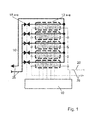
- FIG. 1 schematically shows a thermal storage with any number of memory cells 12a-e.
- Storage media are accommodated in the memory cells 12a-e, wherein the storage media in the individual memory cells 12a-e may differ in their transition temperatures / phase change temperatures.
- a first cooling line 16 is received, through which a first coolant is guided.
- the first cooling lines 16 are each connected to valves 18a-e, via which the supply or the circulation of the first coolant into or to the respective memory cells 12a-e can be controlled.
- a second cooling line 20 is further included, which leads a second coolant to discharge the memory cells 12a-e.
- valves 18a-e are connected to a controller 10.
- temperature measuring devices are included, which determine the temperature of each recorded therein storage media and transmitted to the controller 10.
- the temperature measuring devices are schematically indicated by the dotted line in FIG FIG. 1 shown.
- the controller 10 can determine on the basis of the temperature recorded by the temperature measuring device Whether the storage medium accommodated in the respective memory cell 12a-e is below or above the reversal temperature / phase change temperature of the storage medium. From this, the controller 10 can also determine the state of charge of the respective memory cells 12a-e.
- the temperature, determined by a temperature measuring device, of a storage medium in a selected storage cell 12a-e is below the changeover temperature / phase change temperature of the storage medium, then that storage cell 12a-e is charged. However, if the determined temperature is above the reversal temperature / phase change temperature of the storage medium accommodated in the respective memory cell 12a-e, then the respective memory cell 12a-e is discharged.
- the first coolant is fed via the valves 18a-e and the first cooling lines 16 into the memory cells 12a-e in order to cool the storage medium accommodated therein.
- the supply is controlled by the controller 10 via the opening and closing of the valves 18a-e.
- the supply of the first coolant takes place as shown by the arrow 26.
- the first coolant is brought to a certain temperature, for example, in a chiller, not shown, and then fed via the valves 18a-e to the memory cells 12a-e.
- a second cooling line 20 is also accommodated analogously to the first cooling lines 16, wherein a second coolant is guided in the second cooling lines 20.
- the memory cells 12a-e are discharged.
- the supply of the second coolant takes place as indicated by the arrow 28.
- the controller 10 can determine the (loading) state of charge of the thermal storage, consisting of the individual memory cells 12a-e, by detecting and evaluating the individual states "charged” / "discharged” of the respective memory cells 12a-e. Furthermore, it can be determined via the controller 10, to which memory cells 12a-e the first coolant is supplied.
Landscapes
- Engineering & Computer Science (AREA)
- Physics & Mathematics (AREA)
- Thermal Sciences (AREA)
- Mechanical Engineering (AREA)
- General Engineering & Computer Science (AREA)
- Chemical & Material Sciences (AREA)
- Combustion & Propulsion (AREA)
- Debugging And Monitoring (AREA)
- Devices That Are Associated With Refrigeration Equipment (AREA)
Priority Applications (1)
| Application Number | Priority Date | Filing Date | Title |
|---|---|---|---|
| PL13184425T PL2713122T3 (pl) | 2012-09-27 | 2013-09-13 | Urządzenie do określania stanu załadowania segmentowanego zasobnika termicznego |
Applications Claiming Priority (1)
| Application Number | Priority Date | Filing Date | Title |
|---|---|---|---|
| DE202012103718U DE202012103718U1 (de) | 2012-09-27 | 2012-09-27 | Einrichtung zur Bestimmung des Ladezustands eines segmentierten thermischen Speichers |
Publications (3)
| Publication Number | Publication Date |
|---|---|
| EP2713122A2 true EP2713122A2 (fr) | 2014-04-02 |
| EP2713122A3 EP2713122A3 (fr) | 2016-10-05 |
| EP2713122B1 EP2713122B1 (fr) | 2020-08-19 |
Family
ID=47665689
Family Applications (1)
| Application Number | Title | Priority Date | Filing Date |
|---|---|---|---|
| EP13184425.0A Active EP2713122B1 (fr) | 2012-09-27 | 2013-09-13 | Dispositif de détermination de l'état de charge d'un accumulateur thermique segmenté |
Country Status (5)
| Country | Link |
|---|---|
| EP (1) | EP2713122B1 (fr) |
| DE (1) | DE202012103718U1 (fr) |
| ES (1) | ES2827475T3 (fr) |
| PL (1) | PL2713122T3 (fr) |
| PT (1) | PT2713122T (fr) |
Families Citing this family (3)
| Publication number | Priority date | Publication date | Assignee | Title |
|---|---|---|---|---|
| AT518791B1 (de) * | 2016-12-14 | 2018-01-15 | Ait Austrian Inst Tech Gmbh | Verfahren zum bestimmen eines ladezustandes eines latentwärmespeichers |
| AT524238B1 (de) * | 2021-02-17 | 2022-04-15 | Univ Wien Tech | Verfahren zur Ermittlung des Ladezustandes eines Phasenwechselspeichers |
| CN119042862B (zh) * | 2024-10-08 | 2025-11-25 | 华南理工大学 | 基于峰谷电价的储热型水源热泵供暖控制系统及方法 |
Citations (4)
| Publication number | Priority date | Publication date | Assignee | Title |
|---|---|---|---|---|
| DE2726954A1 (de) | 1977-06-15 | 1979-01-04 | Walter Holzer | Tiefkuehlgeraet mit kaeltespeicher |
| US5598712A (en) | 1992-02-28 | 1997-02-04 | Kabushiki Kaisha Toshiba | Latent heat accumulation system |
| US6481216B2 (en) | 1999-09-22 | 2002-11-19 | The Coca Cola Company | Modular eutectic-based refrigeration system |
| DE102011003441A1 (de) | 2011-02-01 | 2012-08-02 | ZAE Bayern Bayerisches Zentrum für angewandte Energieforschung e.V. | Verfahren zur Bestimmung des Ladezustandes eines Latentwärmespeichers und Latentwärmespeicher mit einer derartigen Ladezustandsanzeige |
Family Cites Families (4)
| Publication number | Priority date | Publication date | Assignee | Title |
|---|---|---|---|---|
| JP2005326078A (ja) * | 2004-05-14 | 2005-11-24 | Matsushita Electric Ind Co Ltd | ヒートポンプ給湯装置 |
| GB0808930D0 (en) * | 2008-05-16 | 2008-06-25 | Sunamp Ltd | Energy Storage system |
| GB0919934D0 (en) * | 2009-11-16 | 2009-12-30 | Sunamp Ltd | Energy storage systems |
| JP5604190B2 (ja) * | 2010-06-24 | 2014-10-08 | パナソニック株式会社 | 蓄熱システム |
-
2012
- 2012-09-27 DE DE202012103718U patent/DE202012103718U1/de not_active Expired - Lifetime
-
2013
- 2013-09-13 PL PL13184425T patent/PL2713122T3/pl unknown
- 2013-09-13 EP EP13184425.0A patent/EP2713122B1/fr active Active
- 2013-09-13 PT PT131844250T patent/PT2713122T/pt unknown
- 2013-09-13 ES ES13184425T patent/ES2827475T3/es active Active
Patent Citations (4)
| Publication number | Priority date | Publication date | Assignee | Title |
|---|---|---|---|---|
| DE2726954A1 (de) | 1977-06-15 | 1979-01-04 | Walter Holzer | Tiefkuehlgeraet mit kaeltespeicher |
| US5598712A (en) | 1992-02-28 | 1997-02-04 | Kabushiki Kaisha Toshiba | Latent heat accumulation system |
| US6481216B2 (en) | 1999-09-22 | 2002-11-19 | The Coca Cola Company | Modular eutectic-based refrigeration system |
| DE102011003441A1 (de) | 2011-02-01 | 2012-08-02 | ZAE Bayern Bayerisches Zentrum für angewandte Energieforschung e.V. | Verfahren zur Bestimmung des Ladezustandes eines Latentwärmespeichers und Latentwärmespeicher mit einer derartigen Ladezustandsanzeige |
Also Published As
| Publication number | Publication date |
|---|---|
| DE202012103718U1 (de) | 2013-01-03 |
| PL2713122T3 (pl) | 2021-03-08 |
| EP2713122A3 (fr) | 2016-10-05 |
| EP2713122B1 (fr) | 2020-08-19 |
| PT2713122T (pt) | 2020-09-30 |
| ES2827475T3 (es) | 2021-05-21 |
Similar Documents
| Publication | Publication Date | Title |
|---|---|---|
| EP3619483B1 (fr) | Meuble frigorifique avec reservoir, systeme de refroidissement et procede de commande d'un meuble frigorifique avec reservoir | |
| DE102014206770A1 (de) | Batteriekühleinrichtung und zugehöriges Betriebsverfahren | |
| DE102010041951A1 (de) | Kältegerät mit einem Kältespeicher | |
| WO2011000826A1 (fr) | Procédé de refroidissement de blocs-batteries et bloc-batterie subdivisé en modules | |
| DE202010007146U1 (de) | Elektrofahrzeug | |
| EP2713122B1 (fr) | Dispositif de détermination de l'état de charge d'un accumulateur thermique segmenté | |
| DE202010001201U1 (de) | Kühlsystem für die Batterie eines Elektrofahrzeugs | |
| EP4111088B1 (fr) | Dispositif d'alimentation en carburant et véhicule comprenant un tel dispositif | |
| WO2017102449A1 (fr) | Procédé de mise en température d'un système énergétique | |
| DE102009057417A1 (de) | Speichervorrichtung und Verfahren zu deren Betrieb | |
| DE202012103715U1 (de) | Einrichtung zur Bestimmung des Ladezustands eines thermischen Speichers | |
| DE102011007626B4 (de) | Latentwärmespeichereinrichtung und Betriebsverfahren für eine Latentwärmespeichereinrichtung | |
| DE102016215368A1 (de) | Anordnung, insbesondere Kältemaschine oder Wärmepumpe | |
| DE102012025192A1 (de) | Verfahren und Vorrichtung zur Vorkonditionierung von Latentwärmespeicherelementen | |
| DE202012103717U1 (de) | Thermischer Speicher für Kälteanlagen | |
| DE102018005503A1 (de) | Vorrichtung zum Unterkühlen von verflüssigten Gasen | |
| DE102015106382A1 (de) | Batterietemperierungsvorrichtung sowie deren Verwendung, Batteriesystem und Fahrzeug mit einem solchen, sowie Verfahren zum Heizen und/oder Kühlen einer Batterie | |
| DE112014005303B4 (de) | Anordnung und Verfahren zum Steuern der Temperatur eines Stromspeichersystems in einem Fahrzeug | |
| DE202009017843U1 (de) | Temperiersystem | |
| DE102011002424A1 (de) | Verfahren zur Startdiagnose eines Wärmespeichermaterials | |
| EP2713120B1 (fr) | Accumulateur thermique pour chambre de refroidissement accessibles | |
| DE102007015391A1 (de) | Kühlfahrzeug mit mehreren Kühlsystemen und Verfahren zur Kühlung | |
| DE102011007606A1 (de) | Verfahren und Vorrichtung zur Homogenisierung der Temperaturverteilung fluidtemperierter Körper | |
| DE102018210147B4 (de) | Wärmemanagement in einem Kraftfahrzeug | |
| DE102010040014A1 (de) | Vorrichtung zur Veränderung einer Umgebungstemperatur für mobile Anwendungen sowie entsprechendes Verfahren |
Legal Events
| Date | Code | Title | Description |
|---|---|---|---|
| PUAI | Public reference made under article 153(3) epc to a published international application that has entered the european phase |
Free format text: ORIGINAL CODE: 0009012 |
|
| AK | Designated contracting states |
Kind code of ref document: A2 Designated state(s): AL AT BE BG CH CY CZ DE DK EE ES FI FR GB GR HR HU IE IS IT LI LT LU LV MC MK MT NL NO PL PT RO RS SE SI SK SM TR |
|
| AX | Request for extension of the european patent |
Extension state: BA ME |
|
| RAP1 | Party data changed (applicant data changed or rights of an application transferred) |
Owner name: VIESSMANN KUEHLSYSTEME GMBH |
|
| PUAL | Search report despatched |
Free format text: ORIGINAL CODE: 0009013 |
|
| AK | Designated contracting states |
Kind code of ref document: A3 Designated state(s): AL AT BE BG CH CY CZ DE DK EE ES FI FR GB GR HR HU IE IS IT LI LT LU LV MC MK MT NL NO PL PT RO RS SE SI SK SM TR |
|
| AX | Request for extension of the european patent |
Extension state: BA ME |
|
| RIC1 | Information provided on ipc code assigned before grant |
Ipc: F25D 11/00 20060101ALI20160901BHEP Ipc: F25D 16/00 20060101AFI20160901BHEP |
|
| STAA | Information on the status of an ep patent application or granted ep patent |
Free format text: STATUS: REQUEST FOR EXAMINATION WAS MADE |
|
| 17P | Request for examination filed |
Effective date: 20170404 |
|
| RBV | Designated contracting states (corrected) |
Designated state(s): AL AT BE BG CH CY CZ DE DK EE ES FI FR GB GR HR HU IE IS IT LI LT LU LV MC MK MT NL NO PL PT RO RS SE SI SK SM TR |
|
| RAP1 | Party data changed (applicant data changed or rights of an application transferred) |
Owner name: VIESSMANN KUEHLSYSTEME GMBH |
|
| STAA | Information on the status of an ep patent application or granted ep patent |
Free format text: STATUS: EXAMINATION IS IN PROGRESS |
|
| 17Q | First examination report despatched |
Effective date: 20190322 |
|
| GRAP | Despatch of communication of intention to grant a patent |
Free format text: ORIGINAL CODE: EPIDOSNIGR1 |
|
| STAA | Information on the status of an ep patent application or granted ep patent |
Free format text: STATUS: GRANT OF PATENT IS INTENDED |
|
| INTG | Intention to grant announced |
Effective date: 20200330 |
|
| RIN1 | Information on inventor provided before grant (corrected) |
Inventor name: ROEMER, SIEGFRIED Inventor name: GEBELEIN, BERND |
|
| GRAS | Grant fee paid |
Free format text: ORIGINAL CODE: EPIDOSNIGR3 |
|
| GRAA | (expected) grant |
Free format text: ORIGINAL CODE: 0009210 |
|
| STAA | Information on the status of an ep patent application or granted ep patent |
Free format text: STATUS: THE PATENT HAS BEEN GRANTED |
|
| AK | Designated contracting states |
Kind code of ref document: B1 Designated state(s): AL AT BE BG CH CY CZ DE DK EE ES FI FR GB GR HR HU IE IS IT LI LT LU LV MC MK MT NL NO PL PT RO RS SE SI SK SM TR |
|
| REG | Reference to a national code |
Ref country code: GB Ref legal event code: FG4D Free format text: NOT ENGLISH |
|
| REG | Reference to a national code |
Ref country code: CH Ref legal event code: EP |
|
| REG | Reference to a national code |
Ref country code: DE Ref legal event code: R082 Ref document number: 502013015030 Country of ref document: DE Representative=s name: DIE PATENTERIE GBR, DE |
|
| REG | Reference to a national code |
Ref country code: DE Ref legal event code: R096 Ref document number: 502013015030 Country of ref document: DE |
|
| REG | Reference to a national code |
Ref country code: AT Ref legal event code: REF Ref document number: 1304395 Country of ref document: AT Kind code of ref document: T Effective date: 20200915 |
|
| REG | Reference to a national code |
Ref country code: IE Ref legal event code: FG4D Free format text: LANGUAGE OF EP DOCUMENT: GERMAN |
|
| REG | Reference to a national code |
Ref country code: PT Ref legal event code: SC4A Ref document number: 2713122 Country of ref document: PT Date of ref document: 20200930 Kind code of ref document: T Free format text: AVAILABILITY OF NATIONAL TRANSLATION Effective date: 20200924 |
|
| REG | Reference to a national code |
Ref country code: FI Ref legal event code: FGE |
|
| REG | Reference to a national code |
Ref country code: SE Ref legal event code: TRGR |
|
| REG | Reference to a national code |
Ref country code: NL Ref legal event code: FP |
|
| REG | Reference to a national code |
Ref country code: LT Ref legal event code: MG4D Ref country code: NO Ref legal event code: T2 Effective date: 20200819 |
|
| PG25 | Lapsed in a contracting state [announced via postgrant information from national office to epo] |
Ref country code: BG Free format text: LAPSE BECAUSE OF FAILURE TO SUBMIT A TRANSLATION OF THE DESCRIPTION OR TO PAY THE FEE WITHIN THE PRESCRIBED TIME-LIMIT Effective date: 20201119 Ref country code: HR Free format text: LAPSE BECAUSE OF FAILURE TO SUBMIT A TRANSLATION OF THE DESCRIPTION OR TO PAY THE FEE WITHIN THE PRESCRIBED TIME-LIMIT Effective date: 20200819 Ref country code: GR Free format text: LAPSE BECAUSE OF FAILURE TO SUBMIT A TRANSLATION OF THE DESCRIPTION OR TO PAY THE FEE WITHIN THE PRESCRIBED TIME-LIMIT Effective date: 20201120 Ref country code: LT Free format text: LAPSE BECAUSE OF FAILURE TO SUBMIT A TRANSLATION OF THE DESCRIPTION OR TO PAY THE FEE WITHIN THE PRESCRIBED TIME-LIMIT Effective date: 20200819 |
|
| PG25 | Lapsed in a contracting state [announced via postgrant information from national office to epo] |
Ref country code: LV Free format text: LAPSE BECAUSE OF FAILURE TO SUBMIT A TRANSLATION OF THE DESCRIPTION OR TO PAY THE FEE WITHIN THE PRESCRIBED TIME-LIMIT Effective date: 20200819 Ref country code: RS Free format text: LAPSE BECAUSE OF FAILURE TO SUBMIT A TRANSLATION OF THE DESCRIPTION OR TO PAY THE FEE WITHIN THE PRESCRIBED TIME-LIMIT Effective date: 20200819 Ref country code: IS Free format text: LAPSE BECAUSE OF FAILURE TO SUBMIT A TRANSLATION OF THE DESCRIPTION OR TO PAY THE FEE WITHIN THE PRESCRIBED TIME-LIMIT Effective date: 20201219 |
|
| PG25 | Lapsed in a contracting state [announced via postgrant information from national office to epo] |
Ref country code: RO Free format text: LAPSE BECAUSE OF FAILURE TO SUBMIT A TRANSLATION OF THE DESCRIPTION OR TO PAY THE FEE WITHIN THE PRESCRIBED TIME-LIMIT Effective date: 20200819 Ref country code: SM Free format text: LAPSE BECAUSE OF FAILURE TO SUBMIT A TRANSLATION OF THE DESCRIPTION OR TO PAY THE FEE WITHIN THE PRESCRIBED TIME-LIMIT Effective date: 20200819 Ref country code: CZ Free format text: LAPSE BECAUSE OF FAILURE TO SUBMIT A TRANSLATION OF THE DESCRIPTION OR TO PAY THE FEE WITHIN THE PRESCRIBED TIME-LIMIT Effective date: 20200819 Ref country code: DK Free format text: LAPSE BECAUSE OF FAILURE TO SUBMIT A TRANSLATION OF THE DESCRIPTION OR TO PAY THE FEE WITHIN THE PRESCRIBED TIME-LIMIT Effective date: 20200819 Ref country code: EE Free format text: LAPSE BECAUSE OF FAILURE TO SUBMIT A TRANSLATION OF THE DESCRIPTION OR TO PAY THE FEE WITHIN THE PRESCRIBED TIME-LIMIT Effective date: 20200819 |
|
| REG | Reference to a national code |
Ref country code: DE Ref legal event code: R097 Ref document number: 502013015030 Country of ref document: DE |
|
| REG | Reference to a national code |
Ref country code: ES Ref legal event code: FG2A Ref document number: 2827475 Country of ref document: ES Kind code of ref document: T3 Effective date: 20210521 |
|
| PG25 | Lapsed in a contracting state [announced via postgrant information from national office to epo] |
Ref country code: AL Free format text: LAPSE BECAUSE OF FAILURE TO SUBMIT A TRANSLATION OF THE DESCRIPTION OR TO PAY THE FEE WITHIN THE PRESCRIBED TIME-LIMIT Effective date: 20200819 Ref country code: MC Free format text: LAPSE BECAUSE OF FAILURE TO SUBMIT A TRANSLATION OF THE DESCRIPTION OR TO PAY THE FEE WITHIN THE PRESCRIBED TIME-LIMIT Effective date: 20200819 |
|
| PLBE | No opposition filed within time limit |
Free format text: ORIGINAL CODE: 0009261 |
|
| STAA | Information on the status of an ep patent application or granted ep patent |
Free format text: STATUS: NO OPPOSITION FILED WITHIN TIME LIMIT |
|
| PG25 | Lapsed in a contracting state [announced via postgrant information from national office to epo] |
Ref country code: SK Free format text: LAPSE BECAUSE OF FAILURE TO SUBMIT A TRANSLATION OF THE DESCRIPTION OR TO PAY THE FEE WITHIN THE PRESCRIBED TIME-LIMIT Effective date: 20200819 Ref country code: LU Free format text: LAPSE BECAUSE OF NON-PAYMENT OF DUE FEES Effective date: 20200913 |
|
| 26N | No opposition filed |
Effective date: 20210520 |
|
| PG25 | Lapsed in a contracting state [announced via postgrant information from national office to epo] |
Ref country code: SI Free format text: LAPSE BECAUSE OF FAILURE TO SUBMIT A TRANSLATION OF THE DESCRIPTION OR TO PAY THE FEE WITHIN THE PRESCRIBED TIME-LIMIT Effective date: 20200819 Ref country code: IE Free format text: LAPSE BECAUSE OF NON-PAYMENT OF DUE FEES Effective date: 20200913 |
|
| PG25 | Lapsed in a contracting state [announced via postgrant information from national office to epo] |
Ref country code: TR Free format text: LAPSE BECAUSE OF FAILURE TO SUBMIT A TRANSLATION OF THE DESCRIPTION OR TO PAY THE FEE WITHIN THE PRESCRIBED TIME-LIMIT Effective date: 20200819 Ref country code: MT Free format text: LAPSE BECAUSE OF FAILURE TO SUBMIT A TRANSLATION OF THE DESCRIPTION OR TO PAY THE FEE WITHIN THE PRESCRIBED TIME-LIMIT Effective date: 20200819 Ref country code: CY Free format text: LAPSE BECAUSE OF FAILURE TO SUBMIT A TRANSLATION OF THE DESCRIPTION OR TO PAY THE FEE WITHIN THE PRESCRIBED TIME-LIMIT Effective date: 20200819 |
|
| PG25 | Lapsed in a contracting state [announced via postgrant information from national office to epo] |
Ref country code: MK Free format text: LAPSE BECAUSE OF FAILURE TO SUBMIT A TRANSLATION OF THE DESCRIPTION OR TO PAY THE FEE WITHIN THE PRESCRIBED TIME-LIMIT Effective date: 20200819 |
|
| PGFP | Annual fee paid to national office [announced via postgrant information from national office to epo] |
Ref country code: NO Payment date: 20220922 Year of fee payment: 10 |
|
| PGFP | Annual fee paid to national office [announced via postgrant information from national office to epo] |
Ref country code: BE Payment date: 20220922 Year of fee payment: 10 |
|
| P01 | Opt-out of the competence of the unified patent court (upc) registered |
Effective date: 20230512 |
|
| PGFP | Annual fee paid to national office [announced via postgrant information from national office to epo] |
Ref country code: NL Payment date: 20230921 Year of fee payment: 11 Ref country code: GB Payment date: 20230920 Year of fee payment: 11 Ref country code: FI Payment date: 20230920 Year of fee payment: 11 Ref country code: AT Payment date: 20230919 Year of fee payment: 11 |
|
| PGFP | Annual fee paid to national office [announced via postgrant information from national office to epo] |
Ref country code: SE Payment date: 20230921 Year of fee payment: 11 Ref country code: PT Payment date: 20230831 Year of fee payment: 11 Ref country code: PL Payment date: 20230828 Year of fee payment: 11 Ref country code: FR Payment date: 20230922 Year of fee payment: 11 |
|
| PGFP | Annual fee paid to national office [announced via postgrant information from national office to epo] |
Ref country code: ES Payment date: 20231002 Year of fee payment: 11 |
|
| PGFP | Annual fee paid to national office [announced via postgrant information from national office to epo] |
Ref country code: IT Payment date: 20230927 Year of fee payment: 11 Ref country code: CH Payment date: 20231001 Year of fee payment: 11 |
|
| REG | Reference to a national code |
Ref country code: BE Ref legal event code: MM Effective date: 20230930 |
|
| PG25 | Lapsed in a contracting state [announced via postgrant information from national office to epo] |
Ref country code: NO Free format text: LAPSE BECAUSE OF NON-PAYMENT OF DUE FEES Effective date: 20230930 |
|
| PG25 | Lapsed in a contracting state [announced via postgrant information from national office to epo] |
Ref country code: BE Free format text: LAPSE BECAUSE OF NON-PAYMENT OF DUE FEES Effective date: 20230930 |
|
| PGFP | Annual fee paid to national office [announced via postgrant information from national office to epo] |
Ref country code: DE Payment date: 20240731 Year of fee payment: 12 |
|
| PG25 | Lapsed in a contracting state [announced via postgrant information from national office to epo] |
Ref country code: PT Free format text: LAPSE BECAUSE OF NON-PAYMENT OF DUE FEES Effective date: 20250313 |
|
| PG25 | Lapsed in a contracting state [announced via postgrant information from national office to epo] |
Ref country code: FI Free format text: LAPSE BECAUSE OF NON-PAYMENT OF DUE FEES Effective date: 20240913 |
|
| REG | Reference to a national code |
Ref country code: SE Ref legal event code: EUG |
|
| REG | Reference to a national code |
Ref country code: CH Ref legal event code: PL |
|
| REG | Reference to a national code |
Ref country code: NL Ref legal event code: MM Effective date: 20241001 |
|
| REG | Reference to a national code |
Ref country code: AT Ref legal event code: MM01 Ref document number: 1304395 Country of ref document: AT Kind code of ref document: T Effective date: 20240913 |
|
| GBPC | Gb: european patent ceased through non-payment of renewal fee |
Effective date: 20240913 |
|
| PG25 | Lapsed in a contracting state [announced via postgrant information from national office to epo] |
Ref country code: NL Free format text: LAPSE BECAUSE OF NON-PAYMENT OF DUE FEES Effective date: 20241001 |
|
| PG25 | Lapsed in a contracting state [announced via postgrant information from national office to epo] |
Ref country code: GB Free format text: LAPSE BECAUSE OF NON-PAYMENT OF DUE FEES Effective date: 20240913 |
|
| PG25 | Lapsed in a contracting state [announced via postgrant information from national office to epo] |
Ref country code: IT Free format text: LAPSE BECAUSE OF NON-PAYMENT OF DUE FEES Effective date: 20240913 |
|
| PG25 | Lapsed in a contracting state [announced via postgrant information from national office to epo] |
Ref country code: FR Free format text: LAPSE BECAUSE OF NON-PAYMENT OF DUE FEES Effective date: 20240930 |
|
| PG25 | Lapsed in a contracting state [announced via postgrant information from national office to epo] |
Ref country code: CH Free format text: LAPSE BECAUSE OF NON-PAYMENT OF DUE FEES Effective date: 20240930 |
|
| PG25 | Lapsed in a contracting state [announced via postgrant information from national office to epo] |
Ref country code: AT Free format text: LAPSE BECAUSE OF NON-PAYMENT OF DUE FEES Effective date: 20240913 |
|
| PG25 | Lapsed in a contracting state [announced via postgrant information from national office to epo] |
Ref country code: SE Free format text: LAPSE BECAUSE OF NON-PAYMENT OF DUE FEES Effective date: 20240914 |
|
| REG | Reference to a national code |
Ref country code: ES Ref legal event code: FD2A Effective date: 20251031 |
|
| PG25 | Lapsed in a contracting state [announced via postgrant information from national office to epo] |
Ref country code: ES Free format text: LAPSE BECAUSE OF NON-PAYMENT OF DUE FEES Effective date: 20240914 |
|
| PG25 | Lapsed in a contracting state [announced via postgrant information from national office to epo] |
Ref country code: PL Free format text: LAPSE BECAUSE OF NON-PAYMENT OF DUE FEES Effective date: 20240913 |