EP2713191B1 - Unterwasser-Kabelabschlussanordnung, Unterwasser-Anschluss und Verfahren - Google Patents
Unterwasser-Kabelabschlussanordnung, Unterwasser-Anschluss und Verfahren Download PDFInfo
- Publication number
- EP2713191B1 EP2713191B1 EP12186843.4A EP12186843A EP2713191B1 EP 2713191 B1 EP2713191 B1 EP 2713191B1 EP 12186843 A EP12186843 A EP 12186843A EP 2713191 B1 EP2713191 B1 EP 2713191B1
- Authority
- EP
- European Patent Office
- Prior art keywords
- subsea
- subsea cable
- electrical
- connector
- media converter
- Prior art date
- Legal status (The legal status is an assumption and is not a legal conclusion. Google has not performed a legal analysis and makes no representation as to the accuracy of the status listed.)
- Active
Links
Images


Classifications
-
- G—PHYSICS
- G02—OPTICS
- G02B—OPTICAL ELEMENTS, SYSTEMS OR APPARATUS
- G02B6/00—Light guides; Structural details of arrangements comprising light guides and other optical elements, e.g. couplings
- G02B6/24—Coupling light guides
- G02B6/42—Coupling light guides with opto-electronic elements
- G02B6/4201—Packages, e.g. shape, construction, internal or external details
- G02B6/4274—Electrical aspects
- G02B6/4278—Electrical aspects related to pluggable or demountable opto-electronic or electronic elements
-
- F—MECHANICAL ENGINEERING; LIGHTING; HEATING; WEAPONS; BLASTING
- F16—ENGINEERING ELEMENTS AND UNITS; GENERAL MEASURES FOR PRODUCING AND MAINTAINING EFFECTIVE FUNCTIONING OF MACHINES OR INSTALLATIONS; THERMAL INSULATION IN GENERAL
- F16L—PIPES; JOINTS OR FITTINGS FOR PIPES; SUPPORTS FOR PIPES, CABLES OR PROTECTIVE TUBING; MEANS FOR THERMAL INSULATION IN GENERAL
- F16L1/00—Laying or reclaiming pipes; Repairing or joining pipes on or under water
- F16L1/12—Laying or reclaiming pipes on or under water
-
- G—PHYSICS
- G02—OPTICS
- G02B—OPTICAL ELEMENTS, SYSTEMS OR APPARATUS
- G02B6/00—Light guides; Structural details of arrangements comprising light guides and other optical elements, e.g. couplings
- G02B6/24—Coupling light guides
- G02B6/36—Mechanical coupling means
- G02B6/38—Mechanical coupling means having fibre to fibre mating means
- G02B6/3807—Dismountable connectors, i.e. comprising plugs
- G02B6/381—Dismountable connectors, i.e. comprising plugs of the ferrule type, e.g. fibre ends embedded in ferrules, connecting a pair of fibres
- G02B6/3816—Dismountable connectors, i.e. comprising plugs of the ferrule type, e.g. fibre ends embedded in ferrules, connecting a pair of fibres for use under water, high pressure connectors
-
- H—ELECTRICITY
- H01—ELECTRIC ELEMENTS
- H01R—ELECTRICALLY-CONDUCTIVE CONNECTIONS; STRUCTURAL ASSOCIATIONS OF A PLURALITY OF MUTUALLY-INSULATED ELECTRICAL CONNECTING ELEMENTS; COUPLING DEVICES; CURRENT COLLECTORS
- H01R13/00—Details of coupling devices of the kinds covered by groups H01R12/70 or H01R24/00 - H01R33/00
- H01R13/46—Bases; Cases
- H01R13/52—Dustproof, splashproof, drip-proof, waterproof, or flameproof cases
- H01R13/523—Dustproof, splashproof, drip-proof, waterproof, or flameproof cases for use under water
-
- H—ELECTRICITY
- H02—GENERATION; CONVERSION OR DISTRIBUTION OF ELECTRIC POWER
- H02G—INSTALLATION OF ELECTRIC CABLES OR LINES, OR OF COMBINED OPTICAL AND ELECTRIC CABLES OR LINES
- H02G15/00—Cable fittings
- H02G15/08—Cable junctions
- H02G15/10—Cable junctions protected by boxes, e.g. by distribution, connection or junction boxes
- H02G15/12—Cable junctions protected by boxes, e.g. by distribution, connection or junction boxes for incorporating transformers, loading coils or amplifiers
- H02G15/14—Cable junctions protected by boxes, e.g. by distribution, connection or junction boxes for incorporating transformers, loading coils or amplifiers specially adapted for submarine cables
-
- H—ELECTRICITY
- H04—ELECTRIC COMMUNICATION TECHNIQUE
- H04B—TRANSMISSION
- H04B10/00—Transmission systems employing electromagnetic waves other than radio-waves, e.g. infrared, visible or ultraviolet light, or employing corpuscular radiation, e.g. quantum communication
- H04B10/80—Optical aspects relating to the use of optical transmission for specific applications, not provided for in groups H04B10/03 - H04B10/70, e.g. optical power feeding or optical transmission through water
-
- G—PHYSICS
- G02—OPTICS
- G02B—OPTICAL ELEMENTS, SYSTEMS OR APPARATUS
- G02B6/00—Light guides; Structural details of arrangements comprising light guides and other optical elements, e.g. couplings
- G02B6/44—Mechanical structures for providing tensile strength and external protection for fibres, e.g. optical transmission cables
- G02B6/4401—Optical cables
- G02B6/4415—Cables for special applications
- G02B6/4427—Pressure resistant cables, e.g. undersea cables
-
- G—PHYSICS
- G02—OPTICS
- G02B—OPTICAL ELEMENTS, SYSTEMS OR APPARATUS
- G02B6/00—Light guides; Structural details of arrangements comprising light guides and other optical elements, e.g. couplings
- G02B6/44—Mechanical structures for providing tensile strength and external protection for fibres, e.g. optical transmission cables
- G02B6/4401—Optical cables
- G02B6/4415—Cables for special applications
- G02B6/4427—Pressure resistant cables, e.g. undersea cables
- G02B6/4428—Penetrator systems in pressure-resistant devices
Definitions
- the invention relates to a subsea cable termination assembly for a subsea cable, to a subsea connector and to a subsea cable assembly. It further relates to corresponding methods.
- Such subsea installations can comprise a range of components, including pumps, compressors and the like as well as a power grid for operating them.
- the power grid may for example comprise a subsea transformer, subsea switchgear and subsea variable speed drives.
- the components of the subsea installation need to be protected from the surrounding sea water, in which pressures of 300 bar or more can prevail (at installation depths of 3.000 m or more).
- Components of such subsea installation can comprise electronic equipment that can be monitored and/or controlled from a topside installation, such as a topside control system which may be located on a fixed or floating vessel, e.g. a ship or a platform, or may be based onshore.
- the subsea installation can for example comprise one or more subsea control modules (SCM) which may receive commands from the topside installation or which may transmit information to the topside installation, which may communicate with each other or which may interface a sensor.
- SCM subsea control modules
- communication links are generally required between the sensors and the subsea control modules, as well as between the subsea control modules and a topside installation.
- Communication may for example be implemented by means of a network communication, such as Ethernet.
- a network communication such as Ethernet.
- Ethernet based on a twisted copper wire pair has a limited length of about 100 m according to Ethernet standards.
- Enhanced solutions may achieve distances exceeding 150 meters length of the communication link.
- communication using such type of technology is thus limited to subsea control modules of the same Christmas tree. A communication between different Christmas trees is usually not possible, each installation requiring their own link to a topside installation via an umbilical or the like.
- the document EP 2354440 A2 discloses a communications connection in a subsea well for converting an optical signal from an optical fibre to an electrical signal.
- the communication connection comprises a small form factor pluggable device.
- the document JP 58 136009 A discloses an underwater connector device for an optical fiber for attaching equipment in a pressure resistant container and an underwater cable without using special equipment.
- An embodiment of the invention provides a subsea cable termination assembly for a subsea cable, the subsea cable including an optical fiber for data transmission.
- the subsea cable termination assembly comprises a chamber which has a liquid tight seal against an ambient medium surrounding the subsea cable termination assembly and a media converter arranged in the chamber, wherein the media converter has an optical interface adapted to be connected to an optical fiber of the subsea cable, the media converter further having an electrical interface.
- the subsea cable termination assembly further comprises an electric contact arranged outside the chamber and electrically connected to the electrical interface of the media converter arranged inside the chamber.
- the media converter is adapted to receive data on one of the electrical or optical interface and to transmit corresponding data on the other of the electrical or optical interface.
- an optical interface of the media converter By making use of an optical interface of the media converter for data transmission over the subsea cable, the distance over which the data can be transmitted can be increased significantly compared to data transmission by twisted copper wires. Since an electric contact is provided for interfacing other subsea components, such as subsea devices, subsea connectors or the like, an electric connector may be used together with the subsea cable termination assembly for connecting the subsea cable to subsea equipment. Reliable and field proven technologies exist for electric subsea connectors, so that the connector can have a relatively low complexity and can be made cost efficiently. In particular, no new wet mateable subsea optical connector is required.
- the electrical interface may certainly be connected to plural electric contacts arranged outside the chamber.
- the subsea cable may comprise plural optical fibers for data transmission, and the optical interface of the media converter may connect to these plural optical fibers.
- the electric contact may be an electric terminal of a connector of the subsea cable.
- the media converter may effectively convert a received optical signal into an electric signal for transmission, or a received electrical signal into an optical signal for transmission. It should be clear that for the transmission of data by means of electrical signals or optical signals, different transmission protocols may be used, and the media converter may be adapted to convert between such protocols.
- the electrical signal and the optical signal may correspond to one or more individual data packets.
- the subsea cable termination assembly may furthermore comprise a fiber optic penetrator for providing an optical connection through a wall of the chamber.
- the fiber optic penetrator may provide a pressure resistant and liquid tight seal.
- the optical fibers of the subsea cable may be fed through the wall of the chamber even if there is a relatively large pressure difference between inside the chamber and outside the chamber.
- a pressure difference between inside and outside of the chamber of close to 300 bar may exist.
- the subsea cable termination assembly may further comprise an electrical penetrator for providing an electric connection through a wall of the chamber.
- the electrical penetrator may provide a pressure resistant and liquid tight seal. Similarly, such electrical penetrator may enable an electric connection through a wall of the chamber while maintaining a liquid tight seal, even if pressure differences in excess of 300 bar between inside and outside of the chamber exist.
- the chamber is filled with a dielectric liquid and is pressure compensated against an ambient pressure.
- the pressure inside the chamber may thus essentially be balanced to the pressure in a medium surrounding the subsea cable termination assembly, e.g. surrounding seawater. In such configuration, the pressure differences between inside and outside of the chamber can be kept small.
- pressure tolerant electric and electronic components may be used for the media converter.
- electric or electronic components of the media converter may be embedded in a material which provides a liquid tight barrier and which is capable of withstanding such high ambient pressures.
- the media converter may comprise a power supply interface for receiving electric power for operation.
- the subsea cable termination assembly may comprise one or more further electrical contacts outside the chamber which are electrically connected to the power supply interface.
- the further electrical contacts may for example be electrical terminals of a connector or may be connected to electrical terminals of a connector. Via such connector, the media converter may thus be supplied with electric power for operation.
- the media converter may further comprise a monitoring interface for providing information about at least an optical link established via the optical interface.
- the monitoring interface may be accessible via the electric contact (it may e.g. correspond to a software interface accessible via data transmission over the electrical interface), or via one or more further electrical contacts provided outside the chamber and electrically connected to the monitoring interface.
- the additional electrical contacts may themselves be or may be connected to electric terminals of a connector, so that via such connector, the status of the optical link can be monitored.
- transmitted and received optical power may for example be monitored.
- Corresponding electric signals may be transmitted by the media converter via the monitoring interface.
- the optical link status may simply be monitored, such as link OK, fail or link activity.
- the media converter may comprise electronic components, and at least some, preferably all of the electronic components are molded into a material, such as a plastic material or a resin.
- electronic components of the media converter may be molded into epoxy resin. This way, the electronic components may be protected from their environment, for example from a dielectric liquid which may at least partly fill the chamber, or from pressure if the chamber is pressure compensated against the ambient medium or is pressurized.
- the electrical contact may be a pin or an electrical socket of a subsea connector. This may also apply to the one or more electrical contacts connected to the power supply interface or the monitoring interface and to other electric contacts which are electrically connected to the media converter.
- the electrical contact may be a male or a female electric contact, depending on the configuration.
- the subsea cable termination assembly may comprise one or more further electric contacts which are electrically connected to respective electric conductors, provided in the subsea cable. Thereby, one or more electric connections may be provided which bypass the media converter. This way, electrical data and/or power transmission may be provided via the subsea cable. As an example, this may be a low bandwidth electric data transmission. Also, since the optical fiber of the subsea cable is available for data transmission, interference by an additional transmission of electric power can be kept low.
- the chamber of the subsea cable termination assembly in which the media converter is arranged may have a cylindrical shape.
- the chamber may have an inner longitudinal dimension between about 50 mm and about 200 mm. It may further have an inner lateral dimension between about 25 mm and about 60 mm.
- a cylindrical chamber having a length of 150 mm and a base diameter of about 45 mm may be used.
- the chamber is provided by a metal housing, such as a steel housing.
- the housing has an opening towards the subsea cable, the opening comprising a fiber optic penetrator.
- the housing has further an opening towards a subsea connector attachable to the housing, and the further opening comprising an electrical penetrator.
- the housing may for example have an interface, such as an NK2 interface, for mounting a subsea connector.
- the subsea cable can be attached thereto.
- the subsea cable termination assembly may further comprise a fill/vent port for the subsea cable.
- a fill/vent port for the subsea cable.
- the subsea cable comprises a liquid filled hose, in which the optical fibers are arranged, such port may be used to fill or vent the liquid filled hose.
- a further embodiment of the invention provides a subsea connector.
- the subsea connector comprises a connector element, such as a receptacle or a plug, for mechanical and electrical engagement, e.g. with another connector, or with a socket or jack on a subsea component or the like.
- the subsea connector further comprises a subsea cable termination assembly in accordance with any of the above described embodiments.
- the electrical contact of the subsea cable termination assembly is a pin or an electrical socket of the connector element.
- Such subsea connector may enable a relatively simple connection and disconnection of the subsea cable at a subsea installation, while at the same time, it enables a data transmission with high bandwidth over long distances.
- the connector element may comprise a receptacle, and the electronic contact may be a pin arranged inside the receptacle.
- the connector element may comprise a plug, and the electrical contact may be an electrical socket arranged inside the plug.
- Other configurations are also conceivable.
- the subsea cable termination assembly may be mechanically mounted to the connector element. It may be arranged between the connector element and the subsea cable.
- a further embodiment of the invention provides a subsea cable assembly which comprises a subsea cable including one or more optical fibers for data transmission and a subsea connector in any of the above outlined configurations.
- the cable termination assembly of the subsea connector terminates the subsea cable at an end thereof and provides an optical connection of the one or more optical fibers to the media converter.
- Such subsea cable assembly may enable an optical transmission of data at relatively high bandwidth over considerable distances, e.g. in access of 1 kilometer.
- such subsea cable assembly may enable a communication between different Christmas trees of a subsea installation. It is thus not necessary to have at each Christmas tree an umbilical to a topside installation, which can result in considerable cost reductions, since umbilicals are generally very expensive.
- advantages similar to the ones outlined further above may be achieved.
- the subsea cable comprises a hose filled with a dielectric liquid, the one or more optical fibers being arranged inside the hose, the hose being flexible to provide pressure compensation between the interior of the hose and an ambient medium.
- a fluid filled hose for example an oil filled hose, can be used in a subsea cable that is operable down to water depths in excess of 3.000 meters.
- the optical fibers and/or the hose may be terminated at the subsea cable termination assembly, and the above mentioned fiber optic penetrator may lead the optical fibers from inside the hose through the wall of the chamber so that they can be connected to the optical interface of the media converter.
- the termination assembly may comprise a fill/vent port for filling or venting the hose.
- Another embodiment of the invention provides a subsea data communication method, which comprises the steps of providing a subsea connector on a subsea cable, the subsea connector having a connector portion with an electrical contact, the subsea connector including a media converter having an electrical interface electrically connected to the electrical contact and an optical interface connected to an optical fiber of the subsea cable; receiving data on one of the electrical or optical interface of the media converter; and transmitting corresponding data on the other of the electrical or optical interface of the media converter.
- the media converter thus essentially performs a conversion of data received as an electrical signal into data to be transmitted as an optical signal and/or vice versa.
- the media converter may furthermore convert the data from one data transmission protocol to another data transmission protocol.
- the method may be performed with a subsea cable termination assembly, a subsea connector or a subsea cable assembly in any of the above outlined configurations.
- Figure 1 shows a subsea cable assembly 100, including a subsea connector 10 and a subsea cable 40.
- the subsea connector 10 comprises a subsea cable termination assembly 20 and a connector portion 30. Note that although these are shown as separate elements here, they may in other embodiments be parts of a subsea connector and may not be separable.
- Subsea connector 10 can be implemented as a male or a female connector.
- subsea connector 10 is a wet mateable connector, although implementations as a dry mate connector are also conceivable.
- the connector portion 30 comprises a connector element 31, which may be a receptacle (in case of a female subsea connector) or may be a plug (in case of a male connector).
- electric contacts 26 are arranged. Again, depending on the configuration, these may be pins or electrical sockets for receiving pins. In fact, other embodiments may use different types of electrical contacts which are known in the art.
- the subsea connector 10 can be mated with another subsea connector or a subsea socket or the like.
- a subsea device such as a power or communication distribution unit, may have several sockets mounted thereto, with which the subsea connector 10 can be brought into engagement, so as to establish an electric connection via the electrical contacts 26.
- data and/or electric power may then be transmitted to a subsea device connected to the other end of the subsea cable 40, e.g. by means of another subsea connector 10.
- Such device can be a subsea control unit or the like.
- the subsea cable assembly 100 may be used to establish a connection between different subsea control units.
- the subsea cable 40 is used for data transmission by means of one or more optical fibers 42.
- the subsea cable 40 may comprise a hose 41, which can be filled with a liquid, such as oil, and in which the one or more optical fibers 42 are arranged.
- a liquid such as oil
- the flexibility of such hose allows a pressure compensation of the interior of the subsea cable 40, so that when deployed subsea, the pressure inside the subsea cable 40 is almost equal to the ambient pressure of the seawater. Due to the low differential pressure, the risk of ingress of seawater into the hose 41 is relatively low.
- a cost efficient and reliable subsea cable 40 can thus be implemented.
- the subsea cable 40 is furthermore provided with a bend restrictor 43, which can be part of the subsea cable termination assembly 20.
- a crimp sleeve (not shown) can furthermore be provided for attaching the hose 41 to the subsea cable termination assembly 20.
- Media converter 22 can then comprise standard electronic components operable in atmospheric conditions.
- Media converter 22 has one or more optical interfaces 24 for connecting to one or more optical fibers 42 of the subsea cable 40.
- the interface and the connection to the optical fibers can be implemented in a variety of ways, depending on the particular needs. Examples are optical connectors or pigtails or the like.
- Media converter 22 further comprises one or more electrical interfaces 23, which are electrically connected to the one or more electric contacts 26.
- the electrical connection can for example be provided by soldered wires, or the interface 23 at media converter 22 may comprise electrical connectors.
- an electrical penetrator 27 and an optical penetrator 28 are provided. These penetrators are configured to provide a liquid tight seal for the chamber 21 to an ambient medium, so that for example liquid from the liquid filled hose 40 or sea water can not enter the chamber 21.
- the penetrators 27 and 28 are configured to withstand the high differential pressures that can prevail when the subsea connector 10 is installed at subsea location.
- a seal may be provided for the optical fiber 42 in optical penetrator 28 by means of molten glass.
- the fiber optic penetrator described in the patent application WO 2009/008738 A1 may be used for this purpose.
- an electrical conductor may be embedded in an insulating material, such as a resin or the like, for providing a sealed connection through the walls of the chamber 21.
- the media converter 22 provides conversion between an optical signal at optical interface 24 and an electrical signal at the electrical interface 23. It may for example convert an electrical signal received via electric connector 26 and electric interface 23 into an optical signal which is transmitted via optical interface 24 on the optical fiber 42. Also, a conversion in the other way may be provided. Preferably, media converter 22 is adapted to convert both from an optical to an electrical signal and from an electrical signal to an optical signal.
- Media converter 22 may be an Ethernet media converter.
- a received optical or electrical signal may correspond to one or more data packets.
- the data may be received via the electrical or optical signals using different types of data transmission protocols. If the protocols are different for the electrical transmission path via interface 23 and the optical data transmission path via the optical interface 24, then media converter 22 may also perform a conversion between the different protocols.
- the subsea cable assembly 100 can thus interface copper Ethernet at both ends, but uses fiber optics as a transportation medium.
- the media converter 22 may be configured to provide a Ethernet data communication with at least 10 Mbit/s, or even at least 100 Mbit/s. In some embodiments, it may even provide a communication with a data rate of one Gbit/s or more. Also, data communication with 10 Gbit/s or more is conceivable.
- the subsea cable 40 can extend over a considerable length, for example exceeding one kilometer.
- a similar subsea connector 10 may be provided, either as a male or a female connector, depending on the configuration.
- the media converter of this second subsea connector can then again perform a conversion between optical and electrical signals, so as to enable a connection of the other end of the cable by an all electrical connector portion to a subsea device, a subsea distribution unit or to another subsea cable.
- the subsea cable assembly 100 enables a high speed communication and the exchange of large amounts of data.
- the data may even be exchanged between different Christmas trees without the need for an umbilical for each Christmas tree, due to the possible length of the subsea cable 40.
- the connector portion of the subsea connector 10 can be kept relatively simple, since only electrical connections need to be established when mating the connector with a corresponding connector or socket. A well proven wet made connector technology can thus be used. In consequence, the subsea connector 10 can be kept relatively compact and cost efficient.
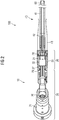
- FIG. 2 shows a particular implementation of the subsea cable assembly 100 including the subsea connector 10 of figure 1 , so the explanations given above are equally applicable to the embodiment illustrated in figure 2 .
- the subsea cable 40 again comprises a hose 41 filled with a liquid, in particular with oil, and the optical fiber 42.
- the hose is mounted to the subsea cable termination assembly 20, e.g. by a crimp sleeve, and a bend restrictor 43 is provided for avoiding an excessive bending of the hose conduit 41.
- a mechanical interface such as an MK2 interface
- the subsea cable can be mounted to the assembly 20.
- the assembly 20 does itself not need to terminate the hose 41, but the end of the subsea cable can be provided with a mechanical interface to which the assembly 20 is attached.
- the assembly 20 will generally terminate the optical link provided by optical fiber 42.
- the assembly 20 may also provide a termination for the subsea cable itself.
- the assembly 20 comprises a housing 25 in which the media converter 22 is arranged.
- the fiber optic penetrator 28 is used to feed the optical fiber 42 through a wall of the housing 25 into the chamber 21 in which the media converter 22 is arranged.
- the subsea connector 10 further comprises the connector portion 30 which is mounted to the assembly 20.
- the assembly 20 may again be provided with a mechanical interface, in particular an MK2 interface, towards which the connector portion 30 can be mounted.
- an MK2 adapter 29 can be affixed to the housing 25 of assembly 20.
- the MK2 adapter provides the MK2 interface towards which the connector portion 30 can be mounted, as shown in figure 2 .
- the assembly 20 comprises an electric penetrator 27 which provides an electric connection through a wall of the housing 25 into the chamber 21 for contacting the media converter 22.
- the penetrator is located in a wall of the housing 25 facing the connector portion 30.
- Electric wires can lead from the penetrator through the connector portion 30 to the electric contacts 26 (pins, electrical sockets or the like) towards which they are connected, e.g. by soldering or the like.
- the electric contacts 26 pins, electrical sockets or the like
- FIG 2 shows the rear ends of the electric contacts 26, whereas the front ends reach through into the connector element 31.
- the connector element 31 is a receptacle which can be engaged with another subsea connector or subsea socket having a plug-type connector element.
- the electric contacts 26 are preferably pins which are protected by the receptacle 31.
- additional electrical connections can be provided in the subsea cable assembly 100, which may bypass the media converter 22, e.g. for providing an electric connection for power supply or for providing a data connection using data transmission by electrical signals, e.g. for legacy systems.
- the assembly 20, in particular the media converter 22, may comprise a microprocessor for evaluating such monitoring data. Such data may then be used to control the media converter (e.g. by adjusting the optical data transmission), and/or may be communicated to another device or a topside installation via the electrical interface for data communication or via dedicated electrical contacts, as mentioned above.
- reference numeral 60 denotes a termination of the subsea cable 40 at the other end thereof, e.g. by another MK2 interface.
- This termination 60 may be attached to a corresponding subsea connector 10 comprising an assembly 20 and a connector portion 30, or it may be directly mounted to a subsea device.
- Other possibilities include the mounting of a dry mate connector to the subsea cable end, which may have optical contacts, or which may be provided with an assembly similar to the assembly 20 comprising a media converter.
- the configuration of the subsea cable assembly 100 depends on the particular application in which it is to be used.
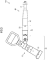
- Figure 3 is a side view of the subsea connector 10 of figure 2 . Since this is not a sectional view, the electric contacts 26 are hidden within the receptacle 31 of the connector portion 30.
- the housing 25 of the assembly 20 is arranged between the connector portion 30 and the subsea cable 40, and the bend restrictor 43 is firmly mounted thereto.
- the housing 25 may for example have an axial extension between about 50mm and about 200mm. Its largest outer diameter may lie within the range of about 30mm to about 100 mm. In the illustrated example, the axial extension is about 100mm and the diameter is about 50mm, in particular about 52mm.
- the housing 25 has an overall cylindrical shape, with a frusto-conical portion at the end facing the connector portion 30.
- Figure 4 shows a perspective view of the subsea cable assembly 100 including the subsea connector 10 of figures 2 and 3 . Note that the length of the subsea cable 40 is reduced for the purpose of illustration, and that the actual length can extend over more than 1 km, since the optical fiber 42 is used for data transmission.
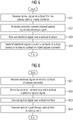
- Figures 5 and 6 are flow diagrams of methods which can be performed by the assembly 20 of any of the above outlined embodiments.
- a data transmission is received on the optical fiber 42 and transmitted via the electric contacts 26 of the subsea connector 10
- a data transmission is received via the electrical contacts 26 of the subsea connector 10 and transmitted through the optical fiber 42.
- an optical signal corresponding to a data transmission is received via the optical fiber of the subsea cable at the optical interface of the media converter.
- the received optical signal is converted into an electrical signal by the media converter (step 502).
- the conversion of the signal may include a change in the data transmission protocol, e.g. by packaging the contents of a data packet received via the optical fiber into a new data packet according to a different protocol for transmission via the electrical interface.
- the media converter then generates an electrical signal corresponding to the new data packet. In other embodiments, only the signal itself may be converted, without affecting the packaging of data.
- step 503 the electrical signal generated by the media converter is given out over the electrical interface.
- the electrical signal is transmitted via the electric contacts 26 to the electric contacts of a mated subsea connector or socket (step 504). It can then be received by a receiver (e.g. network card) of a device to which the socket is mounted, or may be transmitted further by another subsea cable or an umbilical or the like.
- a receiver e.g. network card
- step 601 the electrical signal is received on the electric contacts 26 of the subsea connector 10, and is thus received at the electrical interface 23 of the media converter 22.
- step 602 the electrical signal is converted into an optical signal by the media converter 22.
- the optical signal is then given out via the optical interface 24 of the media converter 22 (step 603).
- the optical signal is transmitted by the optical fiber 42 of the subsea cable (step 604).
- the other end of the subsea cable at which the optical signal is received may comprises a similar subsea connector 10, which may perform the method described with respect to figure 5 on the received optical signal, i.e. it may convert it again into an electrical signal which is given out at its electrical contacts.
- the subsea cable assembly can thus interface copper Ethernet at both ends, but uses fiber optics as a transportation medium.
Landscapes
- Physics & Mathematics (AREA)
- Engineering & Computer Science (AREA)
- General Physics & Mathematics (AREA)
- Optics & Photonics (AREA)
- General Engineering & Computer Science (AREA)
- Power Engineering (AREA)
- Mechanical Engineering (AREA)
- Electromagnetism (AREA)
- Computer Networks & Wireless Communication (AREA)
- Signal Processing (AREA)
- Connector Housings Or Holding Contact Members (AREA)
Claims (13)
- Unterwasser-Kabelanschlussanordnung für ein Unterwasser-Kabel (40), das eine optische Faser (42) zur Datenübertragung enthält, wobei die Unterwasser-Kabelanschlussanordnung (20) Folgendes umfasst:- eine Kammer (21), die eine flüssigkeitsdichte Abdichtung gegen ein Umgebungsmedium aufweist, das die Unterwasser-Kabelanschlussanordnung (20) umgibt,- einen in der Kammer (21) angeordneten Medienumsetzer (22), wobei der Medienumsetzer eine optische Schnittstelle (24) aufweist, die mit einer optischen Faser (42) des Unterwasser-Kabels verbunden werden kann und, ferner eine elektrische Schnittstelle (23) aufweist, und- einen elektrischen Kontakt (26), der außerhalb der Kammer (21) angeordnet und mit der elektrischen Schnittstelle (23) des innerhalb der Kammer angeordneten Medienumsetzers elektrisch verbunden ist,wobei der Medienumsetzer (22) auf einer der elektrischen oder optischen Schnittstelle (23, 24) Daten empfangen und auf der anderen der elektrischen oder optischen Schnittstelle (23, 24) entsprechende Daten übertragen kann,
dadurch gekennzeichnet, dass die Kammer (21) mit einer dielektrischen Flüssigkeit gefüllt und gegen einen Umgebungsdruck druckkompensiert ist. - Unterwasser-Kabelanschlussanordnung nach Anspruch 1, ferner umfassend einen faseroptischen Penetrator (28) zum Bereitstellen einer optischen Verbindung durch eine Wand der Kammer (21), wobei der faseroptische Penetrator eine druckfeste und flüssigkeitsdichte Abdichtung bereitstellt.
- Unterwasser-Kabelanschlussanordnung nach einem der vorhergehenden Ansprüche, ferner umfassend einen elektrischen Penetrator (27) zum Bereitstellen einer elektrischen Verbindung durch eine Wand der Kammer (21), wobei der elektrische Penetrator eine druckfeste und flüssigkeitsdichte Abdichtung bereitstellt.
- Unterwasser-Kabelanschlussanordnung nach einem der vorhergehenden Ansprüche, wobei der Medienumsetzer (22) ferner eine Stromversorgungsschnittstelle zum Empfangen von elektrischem Strom für den Betrieb umfasst, wobei die Unterwasser-Kabelanschlussanordnung ein oder mehr weitere elektrische Kontakte (26) außerhalb der Kammer umfasst und elektrisch mit der Stromversorgungsschnittstelle verbunden ist.
- Unterwasser-Kabelanschlussanordnung nach einem der vorhergehenden Ansprüche, wobei der Medienumsetzer (22) ferner eine Überwachungsschnittstelle zum Bereitstellen von Informationen über die wenigstens eine über die optische Schnittstelle (24) hergestellte optische Verbindung umfasst, wobei die Überwachungsschnittstelle über den elektrischen Kontakt (26) oder über ein oder mehr weitere elektrische Kontakte, die außerhalb der Kammer bereitgestellt und mit der Überwachungsschnittstelle elektrisch verbunden sind, ansprechbar ist.
- Unterwasser-Kabelanschlussanordnung nach einem der vorhergehenden Ansprüche, wobei der Medienumsetzer (22) elektronische Komponenten umfasst, wobei mindestens einige, vorzugsweise alle der elektronischen Komponenten in ein Material, beispielsweise ein Kunststoffmaterial oder ein Harz, vorzugsweise ein Epoxyharz eingeformt sind.
- Unterwasser-Kabelanschlussanordnung nach einem der vorhergehenden Ansprüche, wobei der Medienumsetzer (22) ein Ethernet-Medienumsetzer ist.
- Unterwasser-Kabelanschlussanordnung nach einem der vorhergehenden Ansprüche, wobei die Unterwasser-Kabelanschlussanordnung (20) ein oder mehr weitere elektrische Kontakte (26) umfasst, die mit den jeweiligen in dem Unterwasser-Kabel (40) bereitgestellten elektrischen Leitern elektrisch verbunden sind, wodurch sie ein oder mehr elektrische Verbindungen, die den Medienumsetzer umgehen, zum Bereitstellen von elektrischer Daten- und/oder Stromübertragung über das Unterwasser-Kabel (40) bereitstellt.
- Unterwasser-Kabelanschlussanordnung nach einem der vorhergehenden Ansprüche, wobei die Kammer (21) von einem Metallgehäuse (25), insbesondere einem Stahlgehäuse, bereitgestellt wird, das eine Öffnung zu dem Unterwasser-Kabel (40) aufweist, wobei die Öffnung einen faseroptischen Penetrator (28) umfasst, und eine weitere Öffnung zu einem Unterwasser-Anschlussabschnitt (30) aufweist, der an dem Gehäuse (25) anbringbar ist, wobei die weitere Öffnung einen elektrischen Penetrator (27) umfasst.
- Unterwasser-Anschluss, der ein Anschlusselement (31), insbesondere eine Aufnahme oder einen Stecker, zum mechanischen und elektrischen Eingriff und ferner eine Unterwasser-Kabelanschlussanordnung (20) nach einem der Ansprüche 1 bis 9 umfasst, wobei der elektrische Kontakt (26) der Unterwasser-Kabelanschlussanordnung (20) ein Stift oder eine elektrische Buchse des Anschlusselements (31) ist.
- Unterwasser-Anschluss nach Anspruch 10, wobei die Unterwasser-Kabelanschlussanordnung (20) mechanisch an das Anschlusselement (31) montiert und zwischen dem Anschlusselement (31) und dem Unterwasser-Kabel (40) angeordnet ist.
- Unterwasser-Kabelanordnung (100), die Folgendes umfasst:- ein Unterwasser-Kabel (40), das ein oder mehr optische Fasern (42) zur Datenübertragung enthält,- einen Unterwasser-Anschluss (10) nach Anspruch 10 oder 11,wobei die Kabelanschlussanordnung (20) des Unterwasser-Anschlusses (10) an dem Unterwasser-Kabel (40) an einem Ende davon angebracht ist und eine optische Verbindung der ein oder mehr optischen Fasern (42) mit dem Medienumsetzer (22) bereitstellt.
- Unterwasser-Datenkommunikationsverfahren, das Folgendes umfasst:- Bereitstellen eines Unterwasser-Anschlusses (10) auf einem Unterwasser-Kabel (40), wobei der Unterwasser-Anschluss einen Anschlussabschnitt (30) mit einem elektrischen Kontakt (26) aufweist, wobei der Unterwasser-Anschluss einen Medienumsetzer (20) enthält, der eine elektrische Schnittstelle (23), die mit dem elektrischen Kontakt (26) elektrisch verbunden ist, und eine optische Schnittstelle (24), die mit einer optischen Faser (42) des Unterwasser-Kabels verbunden ist, aufweist, wobei der Medienumsetzer (20) in einer Kammer (21) angeordnet ist, die eine flüssigkeitsdichte Abdichtung gegen ein Umgebungsmedium aufweist, das den Unterwasser-Kabelanschluss (10) umgibt, und wobei die Kammer (21) mit einer dielektrischen Flüssigkeit gefüllt und gegen einen Umgebungsdruck druckkompensiert ist,- Empfangen von Daten über eine der elektrischen oder optischen Schnittstelle (23, 24) des Medienumsetzers (22) und- Übertragen entsprechender Daten über die andere der elektrischen oder optischen Schnittstelle (23, 24) des Medienumsetzers (22).
Priority Applications (4)
| Application Number | Priority Date | Filing Date | Title |
|---|---|---|---|
| EP12186843.4A EP2713191B1 (de) | 2012-10-01 | 2012-10-01 | Unterwasser-Kabelabschlussanordnung, Unterwasser-Anschluss und Verfahren |
| BR102013025265A BR102013025265A2 (pt) | 2012-10-01 | 2013-09-30 | montagem de terminação de cabo submarino, conector submarino e método de comunicação submarina de dados |
| US14/042,589 US9304269B2 (en) | 2012-10-01 | 2013-09-30 | Subsea cable termination assembly, subsea connector and method |
| CN201310455469.XA CN103715646A (zh) | 2012-10-01 | 2013-09-30 | 海底线缆终端组件、海底连接器和方法 |
Applications Claiming Priority (1)
| Application Number | Priority Date | Filing Date | Title |
|---|---|---|---|
| EP12186843.4A EP2713191B1 (de) | 2012-10-01 | 2012-10-01 | Unterwasser-Kabelabschlussanordnung, Unterwasser-Anschluss und Verfahren |
Publications (2)
| Publication Number | Publication Date |
|---|---|
| EP2713191A1 EP2713191A1 (de) | 2014-04-02 |
| EP2713191B1 true EP2713191B1 (de) | 2019-08-28 |
Family
ID=47010317
Family Applications (1)
| Application Number | Title | Priority Date | Filing Date |
|---|---|---|---|
| EP12186843.4A Active EP2713191B1 (de) | 2012-10-01 | 2012-10-01 | Unterwasser-Kabelabschlussanordnung, Unterwasser-Anschluss und Verfahren |
Country Status (4)
| Country | Link |
|---|---|
| US (1) | US9304269B2 (de) |
| EP (1) | EP2713191B1 (de) |
| CN (1) | CN103715646A (de) |
| BR (1) | BR102013025265A2 (de) |
Families Citing this family (23)
| Publication number | Priority date | Publication date | Assignee | Title |
|---|---|---|---|---|
| US9820017B2 (en) * | 2014-08-06 | 2017-11-14 | Teledyne Instruments, Inc. | Subsea connector with data collection and communication system and method |
| WO2016034938A1 (en) * | 2014-09-05 | 2016-03-10 | Onesubsea Llc | Communication distribution unit containing at least one power switch |
| CN105655186B (zh) * | 2014-11-17 | 2018-03-16 | 北京强度环境研究所 | 水密机械式行程开关 |
| EP3104480B1 (de) | 2015-06-09 | 2017-10-04 | Siemens Aktiengesellschaft | Unterseeisches datenübertragungskabel |
| EP3163013B1 (de) | 2015-10-30 | 2018-09-19 | Siemens Aktiengesellschaft | Unterseekommunikationsadapter |
| US10110466B2 (en) * | 2015-11-23 | 2018-10-23 | Tyco Electronics Subsea Communications Llc | Optical communication system with distributed wet plant manager |
| WO2017108214A1 (en) * | 2015-12-22 | 2017-06-29 | Siemens Aktiengesellschaft | Data switch for underwater use |
| DE102016117219A1 (de) * | 2016-03-10 | 2017-09-14 | Voss Automotive Gmbh | Geführte Steckverbindung |
| US9832549B2 (en) * | 2016-03-14 | 2017-11-28 | Teledyne Instruments, Inc. | System, method, and apparatus for subsea optical to electrical distribution |
| CA3009529C (en) | 2016-03-17 | 2018-12-11 | Ormond Energy Innovations Inc. | Protective fiber optic termination, system, and method of using same |
| US10727954B2 (en) * | 2016-06-14 | 2020-07-28 | Teledyne Instruments, Inc. | Long distance subsea can bus distribution system |
| CN106125208A (zh) * | 2016-08-29 | 2016-11-16 | 中天海洋系统有限公司 | 一种高密度水密光连接器 |
| EP3296784B1 (de) * | 2016-09-19 | 2021-07-14 | Siemens Energy AS | Faseroptisches unterwasseranschlussmodul |
| US9979491B2 (en) * | 2016-09-22 | 2018-05-22 | Teledyne Instruments, Inc. | Subsea power-over-fiber can bus converter |
| EP3477114A1 (de) * | 2017-10-25 | 2019-05-01 | Xylem IP Management S.à.r.l. | Tauchfähige elektrische maschinenanordnung |
| US11404815B2 (en) | 2017-10-30 | 2022-08-02 | Ormond Energy Innovations Inc. | Sealed connector with triggered mating and method of using same |
| DE102019123991A1 (de) * | 2019-09-06 | 2021-03-11 | Knorr-Bremse Systeme für Nutzfahrzeuge GmbH | Fahrzeugdrehzahlsensor und Verfahren zur dessen Herstellung |
| GB2587810B (en) * | 2019-10-02 | 2022-04-06 | Siemens Ag | Subsea Connector |
| GB201918323D0 (en) | 2019-12-12 | 2020-01-29 | Siemens Ag | Subsea connector |
| CN112964968B (zh) * | 2021-02-04 | 2022-10-11 | 西安热工研究院有限公司 | 高压套管进行长距离海底高压电缆耐压的试验系统及方法 |
| GB2606006A (en) * | 2021-04-22 | 2022-10-26 | Siemens Energy Global Gmbh & Co Kg | Subsea penetrator |
| CN118962910B (zh) * | 2024-10-16 | 2025-02-11 | 浙江蓝梭海洋科技有限公司 | 一种深海光缆干湿过渡终端接头及其操作方法 |
| CN120559810A (zh) * | 2025-07-29 | 2025-08-29 | 浙江蓝梭海洋科技有限公司 | 一种深海用多芯光纤密封穿舱件及其制作方法 |
Family Cites Families (13)
| Publication number | Priority date | Publication date | Assignee | Title |
|---|---|---|---|---|
| JPS58136009A (ja) * | 1982-02-08 | 1983-08-12 | Sumitomo Electric Ind Ltd | 光フアイバ用水中コネクタ装置 |
| GB2357537B (en) * | 1998-08-06 | 2002-11-20 | Dtc Internat Inc | Subsea control module |
| CA2644216C (en) * | 1998-12-17 | 2011-02-08 | University Of Southampton | Apparatus and method for protecting devices, especially fibre optic devices, in hostile environments |
| US6538198B1 (en) * | 2000-05-24 | 2003-03-25 | Timothy M. Wooters | Marine umbilical |
| US6796821B2 (en) * | 2002-06-06 | 2004-09-28 | Ocean Design, Inc. | Field installable cable termination assembly |
| US7186033B2 (en) * | 2005-02-23 | 2007-03-06 | Schlumberger Technology Corporation | Fiber optic booster connector |
| US7186144B1 (en) * | 2005-12-01 | 2007-03-06 | Adc Telecommunications, Inc. | Connector including media converter |
| US7481584B2 (en) * | 2006-06-30 | 2009-01-27 | Ocean Design, Inc. | Dry mate connector |
| NO327623B3 (no) | 2007-07-11 | 2009-09-07 | Siemens Ag | Subsea fiberoptisk penetrator |
| CN101499636B (zh) * | 2008-01-28 | 2013-07-17 | 普拉德研究及开发股份有限公司 | 油气井组件以及在油气井组件内传输信号的方法 |
| GB2477104B (en) * | 2010-01-21 | 2017-02-22 | Ge Oil & Gas Uk Ltd | Communications connection in a subsea well |
| US20110280538A1 (en) * | 2010-05-17 | 2011-11-17 | Advanced Fiber Products, LLC | Pressure Resistant Media Converter Apparatus |
| US8734026B2 (en) * | 2011-08-19 | 2014-05-27 | Teledyne Instruments, Inc. | Subsea electro-optical connector unit for electro-optical ethernet transmission system |
-
2012
- 2012-10-01 EP EP12186843.4A patent/EP2713191B1/de active Active
-
2013
- 2013-09-30 US US14/042,589 patent/US9304269B2/en active Active
- 2013-09-30 BR BR102013025265A patent/BR102013025265A2/pt not_active Application Discontinuation
- 2013-09-30 CN CN201310455469.XA patent/CN103715646A/zh active Pending
Non-Patent Citations (1)
| Title |
|---|
| None * |
Also Published As
| Publication number | Publication date |
|---|---|
| BR102013025265A2 (pt) | 2016-04-19 |
| EP2713191A1 (de) | 2014-04-02 |
| US20140093247A1 (en) | 2014-04-03 |
| US9304269B2 (en) | 2016-04-05 |
| CN103715646A (zh) | 2014-04-09 |
Similar Documents
| Publication | Publication Date | Title |
|---|---|---|
| EP2713191B1 (de) | Unterwasser-Kabelabschlussanordnung, Unterwasser-Anschluss und Verfahren | |
| EP2745156B1 (de) | Elektrooptische untersee-verbindungseinheit für ein elektrooptische ethernet-übertragungssystem | |
| EP3104480B1 (de) | Unterseeisches datenübertragungskabel | |
| JP2014527697A5 (de) | ||
| US8267707B2 (en) | Underwater or sub sea connectors | |
| US10727954B2 (en) | Long distance subsea can bus distribution system | |
| EP2355258A1 (de) | Steckverbinder | |
| US11038594B1 (en) | Self-insulating high bandwidth connector | |
| US20220050249A1 (en) | Two-part and terminal connectors with conductor management device for use in hazardous environments | |
| CN102193155B (zh) | 海底井中的通信连接 | |
| EP3163013B1 (de) | Unterseekommunikationsadapter | |
| US20260071511A1 (en) | Harness | |
| GB2598394A (en) | Two-part and terminal connectors with improved connector socket sealing and durability | |
| WO2017102034A1 (en) | Arrangement for subsea housing of electric components | |
| EP3369143B1 (de) | Datenschalter für unterwassereinsatz | |
| EP4497910A1 (de) | Unterwassersteuer- und kommunikationssystem | |
| Jenkins et al. | Utilizing pressure balanced oil filled (PBOF) hose cable assemblies with electric and fiber optic connectors | |
| GB2623425A (en) | Harness |
Legal Events
| Date | Code | Title | Description |
|---|---|---|---|
| PUAI | Public reference made under article 153(3) epc to a published international application that has entered the european phase |
Free format text: ORIGINAL CODE: 0009012 |
|
| AK | Designated contracting states |
Kind code of ref document: A1 Designated state(s): AL AT BE BG CH CY CZ DE DK EE ES FI FR GB GR HR HU IE IS IT LI LT LU LV MC MK MT NL NO PL PT RO RS SE SI SK SM TR |
|
| AX | Request for extension of the european patent |
Extension state: BA ME |
|
| 17P | Request for examination filed |
Effective date: 20140929 |
|
| RBV | Designated contracting states (corrected) |
Designated state(s): AL AT BE BG CH CY CZ DE DK EE ES FI FR GB GR HR HU IE IS IT LI LT LU LV MC MK MT NL NO PL PT RO RS SE SI SK SM TR |
|
| RAP1 | Party data changed (applicant data changed or rights of an application transferred) |
Owner name: SIEMENS AKTIENGESELLSCHAFT |
|
| GRAP | Despatch of communication of intention to grant a patent |
Free format text: ORIGINAL CODE: EPIDOSNIGR1 |
|
| STAA | Information on the status of an ep patent application or granted ep patent |
Free format text: STATUS: GRANT OF PATENT IS INTENDED |
|
| RIC1 | Information provided on ipc code assigned before grant |
Ipc: G02B 6/38 20060101AFI20190226BHEP Ipc: H02G 15/14 20060101ALI20190226BHEP Ipc: H01R 13/523 20060101ALI20190226BHEP |
|
| INTG | Intention to grant announced |
Effective date: 20190326 |
|
| GRAS | Grant fee paid |
Free format text: ORIGINAL CODE: EPIDOSNIGR3 |
|
| GRAA | (expected) grant |
Free format text: ORIGINAL CODE: 0009210 |
|
| STAA | Information on the status of an ep patent application or granted ep patent |
Free format text: STATUS: THE PATENT HAS BEEN GRANTED |
|
| AK | Designated contracting states |
Kind code of ref document: B1 Designated state(s): AL AT BE BG CH CY CZ DE DK EE ES FI FR GB GR HR HU IE IS IT LI LT LU LV MC MK MT NL NO PL PT RO RS SE SI SK SM TR |
|
| REG | Reference to a national code |
Ref country code: GB Ref legal event code: FG4D |
|
| REG | Reference to a national code |
Ref country code: CH Ref legal event code: EP |
|
| REG | Reference to a national code |
Ref country code: AT Ref legal event code: REF Ref document number: 1173112 Country of ref document: AT Kind code of ref document: T Effective date: 20190915 |
|
| REG | Reference to a national code |
Ref country code: IE Ref legal event code: FG4D |
|
| REG | Reference to a national code |
Ref country code: DE Ref legal event code: R096 Ref document number: 602012063327 Country of ref document: DE |
|
| REG | Reference to a national code |
Ref country code: NO Ref legal event code: T2 Effective date: 20190828 |
|
| REG | Reference to a national code |
Ref country code: NL Ref legal event code: MP Effective date: 20190828 |
|
| REG | Reference to a national code |
Ref country code: LT Ref legal event code: MG4D |
|
| PG25 | Lapsed in a contracting state [announced via postgrant information from national office to epo] |
Ref country code: HR Free format text: LAPSE BECAUSE OF FAILURE TO SUBMIT A TRANSLATION OF THE DESCRIPTION OR TO PAY THE FEE WITHIN THE PRESCRIBED TIME-LIMIT Effective date: 20190828 Ref country code: LT Free format text: LAPSE BECAUSE OF FAILURE TO SUBMIT A TRANSLATION OF THE DESCRIPTION OR TO PAY THE FEE WITHIN THE PRESCRIBED TIME-LIMIT Effective date: 20190828 Ref country code: BG Free format text: LAPSE BECAUSE OF FAILURE TO SUBMIT A TRANSLATION OF THE DESCRIPTION OR TO PAY THE FEE WITHIN THE PRESCRIBED TIME-LIMIT Effective date: 20191128 Ref country code: SE Free format text: LAPSE BECAUSE OF FAILURE TO SUBMIT A TRANSLATION OF THE DESCRIPTION OR TO PAY THE FEE WITHIN THE PRESCRIBED TIME-LIMIT Effective date: 20190828 Ref country code: NL Free format text: LAPSE BECAUSE OF FAILURE TO SUBMIT A TRANSLATION OF THE DESCRIPTION OR TO PAY THE FEE WITHIN THE PRESCRIBED TIME-LIMIT Effective date: 20190828 Ref country code: FI Free format text: LAPSE BECAUSE OF FAILURE TO SUBMIT A TRANSLATION OF THE DESCRIPTION OR TO PAY THE FEE WITHIN THE PRESCRIBED TIME-LIMIT Effective date: 20190828 Ref country code: PT Free format text: LAPSE BECAUSE OF FAILURE TO SUBMIT A TRANSLATION OF THE DESCRIPTION OR TO PAY THE FEE WITHIN THE PRESCRIBED TIME-LIMIT Effective date: 20191230 |
|
| PG25 | Lapsed in a contracting state [announced via postgrant information from national office to epo] |
Ref country code: ES Free format text: LAPSE BECAUSE OF FAILURE TO SUBMIT A TRANSLATION OF THE DESCRIPTION OR TO PAY THE FEE WITHIN THE PRESCRIBED TIME-LIMIT Effective date: 20190828 Ref country code: IS Free format text: LAPSE BECAUSE OF FAILURE TO SUBMIT A TRANSLATION OF THE DESCRIPTION OR TO PAY THE FEE WITHIN THE PRESCRIBED TIME-LIMIT Effective date: 20191228 Ref country code: LV Free format text: LAPSE BECAUSE OF FAILURE TO SUBMIT A TRANSLATION OF THE DESCRIPTION OR TO PAY THE FEE WITHIN THE PRESCRIBED TIME-LIMIT Effective date: 20190828 Ref country code: AL Free format text: LAPSE BECAUSE OF FAILURE TO SUBMIT A TRANSLATION OF THE DESCRIPTION OR TO PAY THE FEE WITHIN THE PRESCRIBED TIME-LIMIT Effective date: 20190828 Ref country code: GR Free format text: LAPSE BECAUSE OF FAILURE TO SUBMIT A TRANSLATION OF THE DESCRIPTION OR TO PAY THE FEE WITHIN THE PRESCRIBED TIME-LIMIT Effective date: 20191129 Ref country code: RS Free format text: LAPSE BECAUSE OF FAILURE TO SUBMIT A TRANSLATION OF THE DESCRIPTION OR TO PAY THE FEE WITHIN THE PRESCRIBED TIME-LIMIT Effective date: 20190828 |
|
| REG | Reference to a national code |
Ref country code: CH Ref legal event code: NV Representative=s name: SIEMENS SCHWEIZ AG, CH |
|
| REG | Reference to a national code |
Ref country code: AT Ref legal event code: MK05 Ref document number: 1173112 Country of ref document: AT Kind code of ref document: T Effective date: 20190828 |
|
| PG25 | Lapsed in a contracting state [announced via postgrant information from national office to epo] |
Ref country code: TR Free format text: LAPSE BECAUSE OF FAILURE TO SUBMIT A TRANSLATION OF THE DESCRIPTION OR TO PAY THE FEE WITHIN THE PRESCRIBED TIME-LIMIT Effective date: 20190828 |
|
| PG25 | Lapsed in a contracting state [announced via postgrant information from national office to epo] |
Ref country code: IT Free format text: LAPSE BECAUSE OF FAILURE TO SUBMIT A TRANSLATION OF THE DESCRIPTION OR TO PAY THE FEE WITHIN THE PRESCRIBED TIME-LIMIT Effective date: 20190828 Ref country code: EE Free format text: LAPSE BECAUSE OF FAILURE TO SUBMIT A TRANSLATION OF THE DESCRIPTION OR TO PAY THE FEE WITHIN THE PRESCRIBED TIME-LIMIT Effective date: 20190828 Ref country code: RO Free format text: LAPSE BECAUSE OF FAILURE TO SUBMIT A TRANSLATION OF THE DESCRIPTION OR TO PAY THE FEE WITHIN THE PRESCRIBED TIME-LIMIT Effective date: 20190828 Ref country code: AT Free format text: LAPSE BECAUSE OF FAILURE TO SUBMIT A TRANSLATION OF THE DESCRIPTION OR TO PAY THE FEE WITHIN THE PRESCRIBED TIME-LIMIT Effective date: 20190828 Ref country code: DK Free format text: LAPSE BECAUSE OF FAILURE TO SUBMIT A TRANSLATION OF THE DESCRIPTION OR TO PAY THE FEE WITHIN THE PRESCRIBED TIME-LIMIT Effective date: 20190828 Ref country code: PL Free format text: LAPSE BECAUSE OF FAILURE TO SUBMIT A TRANSLATION OF THE DESCRIPTION OR TO PAY THE FEE WITHIN THE PRESCRIBED TIME-LIMIT Effective date: 20190828 |
|
| REG | Reference to a national code |
Ref country code: DE Ref legal event code: R119 Ref document number: 602012063327 Country of ref document: DE |
|
| PG25 | Lapsed in a contracting state [announced via postgrant information from national office to epo] |
Ref country code: CZ Free format text: LAPSE BECAUSE OF FAILURE TO SUBMIT A TRANSLATION OF THE DESCRIPTION OR TO PAY THE FEE WITHIN THE PRESCRIBED TIME-LIMIT Effective date: 20190828 Ref country code: MC Free format text: LAPSE BECAUSE OF FAILURE TO SUBMIT A TRANSLATION OF THE DESCRIPTION OR TO PAY THE FEE WITHIN THE PRESCRIBED TIME-LIMIT Effective date: 20190828 Ref country code: SK Free format text: LAPSE BECAUSE OF FAILURE TO SUBMIT A TRANSLATION OF THE DESCRIPTION OR TO PAY THE FEE WITHIN THE PRESCRIBED TIME-LIMIT Effective date: 20190828 Ref country code: IS Free format text: LAPSE BECAUSE OF FAILURE TO SUBMIT A TRANSLATION OF THE DESCRIPTION OR TO PAY THE FEE WITHIN THE PRESCRIBED TIME-LIMIT Effective date: 20200224 Ref country code: SM Free format text: LAPSE BECAUSE OF FAILURE TO SUBMIT A TRANSLATION OF THE DESCRIPTION OR TO PAY THE FEE WITHIN THE PRESCRIBED TIME-LIMIT Effective date: 20190828 |
|
| REG | Reference to a national code |
Ref country code: CH Ref legal event code: PL |
|
| PLBE | No opposition filed within time limit |
Free format text: ORIGINAL CODE: 0009261 |
|
| STAA | Information on the status of an ep patent application or granted ep patent |
Free format text: STATUS: NO OPPOSITION FILED WITHIN TIME LIMIT |
|
| PG2D | Information on lapse in contracting state deleted |
Ref country code: IS |
|
| PG25 | Lapsed in a contracting state [announced via postgrant information from national office to epo] |
Ref country code: CH Free format text: LAPSE BECAUSE OF NON-PAYMENT OF DUE FEES Effective date: 20191031 Ref country code: LI Free format text: LAPSE BECAUSE OF NON-PAYMENT OF DUE FEES Effective date: 20191031 Ref country code: LU Free format text: LAPSE BECAUSE OF NON-PAYMENT OF DUE FEES Effective date: 20191001 Ref country code: DE Free format text: LAPSE BECAUSE OF NON-PAYMENT OF DUE FEES Effective date: 20200501 |
|
| 26N | No opposition filed |
Effective date: 20200603 |
|
| REG | Reference to a national code |
Ref country code: BE Ref legal event code: MM Effective date: 20191031 |
|
| PG25 | Lapsed in a contracting state [announced via postgrant information from national office to epo] |
Ref country code: BE Free format text: LAPSE BECAUSE OF NON-PAYMENT OF DUE FEES Effective date: 20191031 Ref country code: SI Free format text: LAPSE BECAUSE OF FAILURE TO SUBMIT A TRANSLATION OF THE DESCRIPTION OR TO PAY THE FEE WITHIN THE PRESCRIBED TIME-LIMIT Effective date: 20190828 |
|
| PG25 | Lapsed in a contracting state [announced via postgrant information from national office to epo] |
Ref country code: IE Free format text: LAPSE BECAUSE OF NON-PAYMENT OF DUE FEES Effective date: 20191001 |
|
| REG | Reference to a national code |
Ref country code: NO Ref legal event code: CHAD Owner name: SIEMENS ENERGY AS, NO |
|
| REG | Reference to a national code |
Ref country code: GB Ref legal event code: 732E Free format text: REGISTERED BETWEEN 20210325 AND 20210331 |
|
| PG25 | Lapsed in a contracting state [announced via postgrant information from national office to epo] |
Ref country code: CY Free format text: LAPSE BECAUSE OF FAILURE TO SUBMIT A TRANSLATION OF THE DESCRIPTION OR TO PAY THE FEE WITHIN THE PRESCRIBED TIME-LIMIT Effective date: 20190828 |
|
| PG25 | Lapsed in a contracting state [announced via postgrant information from national office to epo] |
Ref country code: HU Free format text: LAPSE BECAUSE OF FAILURE TO SUBMIT A TRANSLATION OF THE DESCRIPTION OR TO PAY THE FEE WITHIN THE PRESCRIBED TIME-LIMIT; INVALID AB INITIO Effective date: 20121001 Ref country code: MT Free format text: LAPSE BECAUSE OF FAILURE TO SUBMIT A TRANSLATION OF THE DESCRIPTION OR TO PAY THE FEE WITHIN THE PRESCRIBED TIME-LIMIT Effective date: 20190828 |
|
| PG25 | Lapsed in a contracting state [announced via postgrant information from national office to epo] |
Ref country code: MK Free format text: LAPSE BECAUSE OF FAILURE TO SUBMIT A TRANSLATION OF THE DESCRIPTION OR TO PAY THE FEE WITHIN THE PRESCRIBED TIME-LIMIT Effective date: 20190828 |
|
| PGFP | Annual fee paid to national office [announced via postgrant information from national office to epo] |
Ref country code: GB Payment date: 20251023 Year of fee payment: 14 |
|
| PGFP | Annual fee paid to national office [announced via postgrant information from national office to epo] |
Ref country code: NO Payment date: 20251022 Year of fee payment: 14 |
|
| PGFP | Annual fee paid to national office [announced via postgrant information from national office to epo] |
Ref country code: FR Payment date: 20251027 Year of fee payment: 14 |