EP2713267A2 - Steuerung der Audiosignaleigenschaften einer elektronischen Vorrichtung - Google Patents
Steuerung der Audiosignaleigenschaften einer elektronischen Vorrichtung Download PDFInfo
- Publication number
- EP2713267A2 EP2713267A2 EP12192163.9A EP12192163A EP2713267A2 EP 2713267 A2 EP2713267 A2 EP 2713267A2 EP 12192163 A EP12192163 A EP 12192163A EP 2713267 A2 EP2713267 A2 EP 2713267A2
- Authority
- EP
- European Patent Office
- Prior art keywords
- audio
- output
- signals
- electronic device
- audio output
- Prior art date
- Legal status (The legal status is an assumption and is not a legal conclusion. Google has not performed a legal analysis and makes no representation as to the accuracy of the status listed.)
- Granted
Links
Images




Classifications
-
- G—PHYSICS
- G06—COMPUTING OR CALCULATING; COUNTING
- G06F—ELECTRIC DIGITAL DATA PROCESSING
- G06F3/00—Input arrangements for transferring data to be processed into a form capable of being handled by the computer; Output arrangements for transferring data from processing unit to output unit, e.g. interface arrangements
- G06F3/16—Sound input; Sound output
- G06F3/165—Management of the audio stream, e.g. setting of volume, audio stream path
-
- G—PHYSICS
- G06—COMPUTING OR CALCULATING; COUNTING
- G06F—ELECTRIC DIGITAL DATA PROCESSING
- G06F1/00—Details not covered by groups G06F3/00 - G06F13/00 and G06F21/00
- G06F1/16—Constructional details or arrangements
- G06F1/1613—Constructional details or arrangements for portable computers
- G06F1/1633—Constructional details or arrangements of portable computers not specific to the type of enclosures covered by groups G06F1/1615 - G06F1/1626
- G06F1/1684—Constructional details or arrangements related to integrated I/O peripherals not covered by groups G06F1/1635 - G06F1/1675
- G06F1/1688—Constructional details or arrangements related to integrated I/O peripherals not covered by groups G06F1/1635 - G06F1/1675 the I/O peripheral being integrated loudspeakers
-
- G—PHYSICS
- G06—COMPUTING OR CALCULATING; COUNTING
- G06F—ELECTRIC DIGITAL DATA PROCESSING
- G06F1/00—Details not covered by groups G06F3/00 - G06F13/00 and G06F21/00
- G06F1/16—Constructional details or arrangements
- G06F1/1613—Constructional details or arrangements for portable computers
- G06F1/1633—Constructional details or arrangements of portable computers not specific to the type of enclosures covered by groups G06F1/1615 - G06F1/1626
- G06F1/1684—Constructional details or arrangements related to integrated I/O peripherals not covered by groups G06F1/1635 - G06F1/1675
- G06F1/1694—Constructional details or arrangements related to integrated I/O peripherals not covered by groups G06F1/1635 - G06F1/1675 the I/O peripheral being a single or a set of motion sensors for pointer control or gesture input obtained by sensing movements of the portable computer
-
- H—ELECTRICITY
- H04—ELECTRIC COMMUNICATION TECHNIQUE
- H04R—LOUDSPEAKERS, MICROPHONES, GRAMOPHONE PICK-UPS OR LIKE ACOUSTIC ELECTROMECHANICAL TRANSDUCERS; ELECTRIC HEARING AIDS; PUBLIC ADDRESS SYSTEMS
- H04R5/00—Stereophonic arrangements
- H04R5/04—Circuit arrangements, e.g. for selective connection of amplifier inputs/outputs to loudspeakers, for loudspeaker detection, or for adaptation of settings to personal preferences or hearing impairments
-
- G—PHYSICS
- G06—COMPUTING OR CALCULATING; COUNTING
- G06F—ELECTRIC DIGITAL DATA PROCESSING
- G06F2200/00—Indexing scheme relating to G06F1/04 - G06F1/32
- G06F2200/16—Indexing scheme relating to G06F1/16 - G06F1/18
- G06F2200/161—Indexing scheme relating to constructional details of the monitor
- G06F2200/1614—Image rotation following screen orientation, e.g. switching from landscape to portrait mode
-
- G—PHYSICS
- G06—COMPUTING OR CALCULATING; COUNTING
- G06F—ELECTRIC DIGITAL DATA PROCESSING
- G06F2200/00—Indexing scheme relating to G06F1/04 - G06F1/32
- G06F2200/16—Indexing scheme relating to G06F1/16 - G06F1/18
- G06F2200/163—Indexing scheme relating to constructional details of the computer
- G06F2200/1637—Sensing arrangement for detection of housing movement or orientation, e.g. for controlling scrolling or cursor movement on the display of an handheld computer
-
- H—ELECTRICITY
- H04—ELECTRIC COMMUNICATION TECHNIQUE
- H04R—LOUDSPEAKERS, MICROPHONES, GRAMOPHONE PICK-UPS OR LIKE ACOUSTIC ELECTROMECHANICAL TRANSDUCERS; ELECTRIC HEARING AIDS; PUBLIC ADDRESS SYSTEMS
- H04R2420/00—Details of connection covered by H04R, not provided for in its groups
- H04R2420/01—Input selection or mixing for amplifiers or loudspeakers
-
- H—ELECTRICITY
- H04—ELECTRIC COMMUNICATION TECHNIQUE
- H04R—LOUDSPEAKERS, MICROPHONES, GRAMOPHONE PICK-UPS OR LIKE ACOUSTIC ELECTROMECHANICAL TRANSDUCERS; ELECTRIC HEARING AIDS; PUBLIC ADDRESS SYSTEMS
- H04R2420/00—Details of connection covered by H04R, not provided for in its groups
- H04R2420/03—Connection circuits to selectively connect loudspeakers or headphones to amplifiers
-
- H—ELECTRICITY
- H04—ELECTRIC COMMUNICATION TECHNIQUE
- H04R—LOUDSPEAKERS, MICROPHONES, GRAMOPHONE PICK-UPS OR LIKE ACOUSTIC ELECTROMECHANICAL TRANSDUCERS; ELECTRIC HEARING AIDS; PUBLIC ADDRESS SYSTEMS
- H04R2499/00—Aspects covered by H04R or H04S not otherwise provided for in their subgroups
- H04R2499/10—General applications
- H04R2499/11—Transducers incorporated or for use in hand-held devices, e.g. mobile phones, PDA's, camera's
-
- H—ELECTRICITY
- H04—ELECTRIC COMMUNICATION TECHNIQUE
- H04R—LOUDSPEAKERS, MICROPHONES, GRAMOPHONE PICK-UPS OR LIKE ACOUSTIC ELECTROMECHANICAL TRANSDUCERS; ELECTRIC HEARING AIDS; PUBLIC ADDRESS SYSTEMS
- H04R2499/00—Aspects covered by H04R or H04S not otherwise provided for in their subgroups
- H04R2499/10—General applications
- H04R2499/13—Acoustic transducers and sound field adaptation in vehicles
Definitions
- the present disclosure generally relates an electronic device which can be configured to vary/control audio characteristics of input audio signals and/or output of audio output signals based on any of, or any combination of, image signals, optical signals, voice input signals, movement of the electronic device and change in orientation of the electronic device.
- Portable electronic devices such as electronic tablet devices are becoming more and more popular.
- An electronic tablet device can be used for entertainment purposes such as video and/or audio playback.
- an electronic tablet device can be regarded as an electronic audio reproduction device having speaker drivers for output of audio signals during audio playback.
- audio signals are usually output in a fixed general direction.
- the general output direction of audio signals from a conventional electronic audio reproduction device may be determined by the direction which each of the speaker drivers is facing.
- a user of a conventional electronic audio reproduction device may find it necessary to either adjust his/her listening position relative to where the electronic audio reproduction device is positioned or make adjustments to the position of the electronic audio reproduction device relative to his/her listening position.
- an electronic device can include a processing portion and a plurality of audio output portions.
- the plurality of audio output portions can be coupled to the processing portion.
- the processing portion can be configured to receive and process audio input signals in a manner so as to produce audio output signals.
- the audio input signals can be associated with audio characteristics and a plurality of frequency ranges.
- the plurality of audio output portions can be coupled to the processing portion such that audio output signals can be communicated to the audio output portions from the processing portion for output.
- the electronic device can be positioned in at least a first orientation and a second orientation. Orientation of the electronic device can be changed between the first and second orientations. For example, the electronic device can initially be positioned in the first orientation and orientation of the electronic device can be changed to the second orientation.
- the electronic device can be moved between at least a first location and a second location.
- location of the electronic device can, for example, be changed between the first and second locations.
- the electronic device can initially be located in the first location and, by moving the electronic device, location of the electronic device can be changed to the second location.
- processing portion can be further configured to receive and process one or both of image signals and voice input signals.
- the processing portion can be further configured to receive and process optical signals.
- the processing portion can be further configured to do one of or any combination of the following:
- output of audio output signals can be varied/controlled in the context of one of or any combination of the following:
- the electronic device can, in one exemplary application, be suitable for use with another electronic device such as a media player device.
- the media player device can be configured to communicate audio signals corresponding to audio input signals.
- audio characteristics of the audio input signals relate to at least one of frequency characteristics, phase characteristics, amplitude and channel characteristics, and output of audio output signals can further be controlled/varied in the context of time delay in the output of at least a portion of the audio output portions.
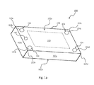
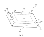
- an electronic device 100 is shown in accordance with an embodiment of the disclosure.
- the electronic device 100 can, for example, be an electronic tablet device.
- the electronic device 100 can include a casing 102.
- the casing 102 can include a first face 102a, a second face 102b and sides 102c.
- the first face 102a and the second face 102b are opposite each other and are spaced apart such that sides 102c are defined between the first and second faces 102a/102b.
- the casing 102 can include a first corner 103a, a second corner 103b, a third corner 103c and a fourth corner 103d.
- the electronic device 100 can include one or more audio output portions 104. Preferably, the electronic device 100 includes a plurality of audio output portions 104.
- the electronic device 100 can, optionally, further include one or both of a display module 105 and an image capture module 106.
- the electronic device 100 can, optionally, yet further include one or more photonic based detectors/sensors (not shown).
- the casing 102 can be shaped and dimensioned to carry the audio output portions 104.
- the casing 102 can be further shaped and dimensioned to carry the display module 105.
- the casing 102 can yet be further shaped and dimensioned to carry the image capture module 106 and/or one or more photonic based detectors/sensors.
- the audio output portions 104 can be carried at one or both of the first face 102a and the second face 102b.
- the audio output portions 104 can be carried at the first face 102a of the casing and can be arranged along the edges of the first face 102a.
- the audio output portions 104 can, for example, be speaker drivers configured to output audio signals.
- the display module 105, the image capture module 106 and the one or more photonic based detectors/sensors can be carried at the first face 102a of the casing 102.
- the display module 105 can be positioned at substantially the center of the first face 102a and the image capture module 106 can be arranged along an edge of the first face 102a.
- the photonic based detectors/sensors can be arranged along an edge of the first face 102a.
- the display module 105 can, for example, be a touch sensitive screen such a liquid crystal display (LCD) screen.
- the image capture module 106 can, for example, be a webcam or a camera sensor with fisheye type lens.
- the aforementioned one or more photonic based detectors/sensors can, for example, be one or more infrared (IR) sensors.
- IR infrared
- the audio output portions 104 can be carried at the first face 102a of the casing and can be arranged along the edges of the first face 102a. Further earlier mentioned, the audio output portions 104 can, for example, be speaker drivers.
- the audio output portions 104 can include a first speaker driver 104a, a second speaker driver 104b, a third speaker driver 104c and a fourth speaker driver 104d.
- the speaker drivers 104a/104b/104c/104d can be positioned along the edges of the first face 102a such that a speaker driver is located adjacent or at a corner of the first face 102a.
- the first speaker driver 104a can be located adjacent/at the first corner 103a
- the second speaker driver 104b can be located adjacent/at the second corner 103b
- the third speaker driver 104c can be located adjacent/at the third corner 103c
- the fourth speaker driver 104d can be located adjacent/at the fourth corner 103d.
- the audio output portions 104 can include a first speaker driver 104a and a second speaker driver 104b.
- the speaker drivers 104a/104b can be positioned along the edges of the first face 102a such that they are located adjacent or at diagonal corners of the casing 102.
- the first speaker driver 104a can be positioned adjacent/at the first corner 103a and second speaker driver 104b can be positioned adjacent/at the fourth corner 103d which is diagonal to the first corner 103a.
- the first and second speaker drivers 104a/104b can be positioned along the edges of the first face 102a such that they are located along opposing edges of the first face 102a.
- the first speaker 104a can be positioned in the middle along a first edge of the first face 102a and the second speaker 104b can be positioned in the middle along a second edge of the first face 102a. The first edge is opposite the second edge.
- the audio output portions 104 can include a first speaker driver 104a, a second speaker driver 104b and a third speaker driver 104c.
- the first speaker driver 104a can be arranged along a first edge 108 of the first face 102a.
- the second and third speaker drivers 104b/104c can be arranged along a second edge 110 of the first face 102a.
- the first edge 108 is opposite the second edge 110.
- the first speaker driver 104a can be positioned in the middle along the first edge 108
- the second speaker driver 104b can be positioned at one end of the second edge 110
- the third speaker driver 104c can be positioned at another end of the second edge 110.
- the audio output portions 104 are arranged along the edges of the first face 102a in a manner such that for one or more audio output portions 104 arranged along one edge of the first face 102a, one or more other audio output portions 104 are arranged along an opposite edge of the first face 102a.
- the electronic device 100 can, in accordance with another embodiment of the disclosure, include one or more protrusions 200.
- the electronic device 100 includes a plurality of protrusions 200.
- Fig. 2a to Fig. 2h will be discussed with reference to a plurality of protrusions 200. It is appreciable that the following discussion can similarly apply to a scenario where the electronic device 100 includes one protrusion 200.
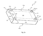
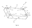
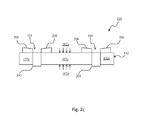
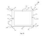
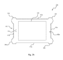
- Fig. 2a to Fig. 2c show a first exemplary arrangement where the protrusions 200 can be extending/protruding from one or both of the first face 102a and the second face 102b of the casing 102.
- Fig. 2d to Fig. 2h show a second exemplary arrangement where the protrusions 200 can be extending/protruding from at least one of the sides 102c of the casing 102.
- the protrusions 200 extend/protrude from the sides 102c of the casing 102.
- Fig. 2a shows a first perspective view with reference to the first face 102a of the casing 102.
- Fig. 2b shows a second perspective view with reference to the second face 102b of the casing 102.
- Fig. 2c shows a side view with reference to one of the sides 102c of the casing 102.
- Fig. 2d shows, in one example, the protrusions 200 can extend from any of, or any combination of, the first to fourth corners 103a/103b/103c/103d of the casing 102.
- Fig. 2e to Fig. 2h show that the protrusions 200 can be in various shapes and/or sizes.
- the protrusions 200 can extend from one or both of the first face 102a and the second face 102b of the casing 102.
- Fig. 2a to Fig. 2c will be discussed later in further detail.
- the protrusions 200 can extend from the sides 102c of the casing 102.
- a protrusion 200 can extend from each of the first to fourth corners 103a/103b/103c/103d of the casing 102.
- the protrusions 200 can extend from/relative to one or both of the first face 102a and the second face 102b of the casing 102.
- protrusions 200 extend from the sides 102c, it is also possible that they further extend from/relative to one or both of the first face 102a and the second face 102b. Fig. 2d will be discussed later in further detail.
- the number of protrusions 200 corresponds to the number of audio output portions 104.
- the audio output portions 104 can include a first speaker driver 104a, a second speaker driver 104b, a third speaker driver 104c and a fourth speaker driver 104d.
- the protrusions 200 can include a first protrusion, a second protrusion, a third protrusion and a fourth protrusion corresponding to the first speaker driver 104a, the second speaker driver 104b, the third speaker driver 104c and the fourth speaker driver 104d respectively.
- Fig. 2a to Fig. 2c show that the protrusions 200 can extend from one or both of the first face 102a and the second face 102b of the casing 102.
- Fig. 2a to Fig. 2c will be discussed in further detail hereinafter.
- protrusions 200 can extend from the first face 102a of the casing 102.
- the protrusions 200 can correspond to the audio output portions 104 protruding from the first face 102a of the casing 102.
- a protrusion 200 can correspond to an audio output portion 104 or at least a portion of an audio output portion 104 protruding from the first face 102a of the casing 102.
- at least a portion of an audio output portion 104 can be protruding from the first face 102a of the casing 102, and can thus be exposed to view.
- the at least a portion of the audio output portion 104, protruding from the casing 102 and exposed to view can correspond to a protrusion 200.
- the casing 102 can be shaped and dimensioned in a manner so as to form the protrusions 200 such that they extend from the first face 102a of the casing 102. Additionally, the casing 102 can be shaped and dimensioned in a manner so as to form the protrusions 200 which can carry the audio output portions 104.
- a protrusion 200 can carry a corresponding audio output portion 104 or at least a portion of a corresponding audio output portion 104.
- the first protrusion can carry the first speaker driver 104a or at least a portion of the first speaker driver 104a.
- the second to fourth protrusions can carry, respectively, the second to fourth speaker drivers 104b/104c/104d or at least a portion of the second to fourth speaker drivers 104b/104c/104d.
- protrusions 200 can extend from the second face 102b of the casing 102.
- the protrusions 200 can correspond to the audio output portions 104 protruding from the second face 102b of the casing 102.
- a protrusion 200 can correspond to an audio output portion 104 or at least a portion of an audio output portion 104 protruding from the second face 102b of the casing 102.
- at least a portion of an audio output portion 104 can be protruding from the second face 102b of the casing 102, and can thus be exposed to view.
- the at least a portion of the audio output portion 104, protruding from the casing 102 and exposed to view can correspond to a protrusion 200.
- the casing 102 can be shaped and dimensioned in a manner so as to form the protrusions 200 such that they extend from the second face 102b of the casing 102. Additionally, the casing 102 can be shaped and dimensioned in a manner so as to form the protrusions 200 which can carry the audio output portions 104.
- a protrusion 200 can carry a corresponding audio output portion 104 or at least a portion of a corresponding audio output portion 104.
- the first protrusion can carry the first speaker driver 104a or at least a portion of the first speaker driver 104a.
- the second to fourth protrusions can carry, respectively, the second to fourth speaker drivers 104b/104c/104d or at least a portion of the second to fourth speaker drivers 104b/104c/104d.
- the second face 102b can include one or more openings/perforations 202.
- the second face 102b includes a plurality of openings/perforations 202.
- the number of openings/perforations 202 can be based on the number of audio output portions 104.
- the number of openings/perforations 202 corresponds to the number of audio output portions 104.
- the plurality of openings/perforations 202 can include a first opening/perforation, a second opening/perforation, a third opening/perforation and a fourth opening/perforation corresponding to the first speaker driver 104a, the second speaker driver 104b, the third speaker driver 104c and the fourth speaker driver 104d respectively.
- the openings/perforations 202 can be arranged on the second face 102b based on the arrangement of the audio output portions 104. Specifically, the arrangement of the openings/perforations 202 on the second face 102b can be dependent on the arrangement of the audio output portions 104.
- Fig. 2c a side view with reference to one of the sides 102c of the casing 102 is shown.
- Fig. 2c 's side view is a "see through” view which presents the arrangement of at least a portion of the audio output portions 104 within the casing 102.
- the protrusions 200 can extend from the first and second faces 102a/102b of the casing.
- the protrusions 200 can correspond to the audio output portions 104 protruding from one or both of the first and second faces 102a/102b of the casing 102.
- a protrusion 200 can correspond to an audio output portion 104 or at least a portion of an audio output portion 104 protruding from one or both of the first and second faces 102a/102b of the casing 102.
- at least a portion of an audio output portion 104 can be protruding from one or both of the first and second faces 102a/102b of the casing 102, and can thus be exposed to view.
- the at least a portion of the audio output portion 104, protruding from the casing 102 and exposed to view can correspond to a protrusion 200.
- the casing 102 can be shaped and dimensioned in a manner so as to form the protrusions 200 which can carry the audio output portions 104. Additionally, the casing 102 can be shaped and dimensioned to form the protrusions 200 in a manner such that they extend from one or both of the first and second faces 102a/102b of the casing 102.
- a protrusion 200 can carry a corresponding audio output portion 104 or at least a portion of a corresponding audio output portion 104.
- the first protrusion can carry the first speaker driver 104a or at least a portion of the first speaker driver 104a.
- the second to fourth protrusions can carry, respectively, the second to fourth speaker drivers 104b/104c/104d or at least a portion of the second to fourth speaker drivers 104b/104c/104d.
- the number of protrusions 200 can correspond to the number of audio output portions 104.
- the number of protrusions 200 can be four (i.e., first to fourth protrusions).
- the protrusions 200 discussed with reference to Fig. 2a to Fig. 2c can be helpful in protecting the electronic device 100.
- the electronic device 100 when the electronic device 100 is placed on a flat surface (not shown), direct contact between of the flat surface and any of the first face 102a, the second face 102b, the display module 105 and/or the image capture module 106 can be prevented. In this manner, scratches to the first face 102a, the second face 102b, the display module 105 and/or the image capture module 106 can be prevented.
- the protrusions 200 can help prevent substantial damage such as impact damage and/or shock damage to the first face 102a, the second face 102b, the display module 105 and/or the image capture module 106.
- Fig. 2d shows that the protrusions 200 can extend from the sides 102c of the casing 102. Fig. 2d will be discussed in further detail hereinafter.
- the protrusions 200 can extend from the sides 102c of the casing 102.
- the first protrusion, the second protrusion, the third protrusion and the fourth protrusion can extend from the first corner 103a, the second corner 103b, the third corner 103c and the fourth corner 103d respectively.
- any of or any combination of the first to fourth protrusions can optionally extend from/relative to one or both of the first and second faces 102a/102b.
- a protrusion 200 can, in one example, extend from a side 102c and, at the same time, extend relative to one or both of the first and second faces 102a/102b.
- the protrusion 200 need not necessarily extend directly from one or both of the first and second faces 102a/102b.
- the protrusions 200 can correspond to the audio output portions 104 protruding from the sides 102c of the casing 102.
- the protrusions can further correspond to the audio output portions 104 protruding from/relative to one or both of the first face 102a and the second face 102b of the casing 102.
- a protrusion 200 can correspond to an audio output portion 104 or at least a portion of an audio output portion 104 protruding from the first face 102a, the second face 102b and/or the side 102c of the casing 102.
- an audio output portion 104 can be protruding from/ relative to one or both of the first and second faces 102a/102b and/or sides 102c of the casing 102, and can thus be exposed to view.
- the at least a portion of the audio output portion 104, protruding from the casing 102 and exposed to view, can correspond to a protrusion 200.
- the casing 102 can be shaped and dimensioned in a manner so as to form the protrusions 200 which can carry the audio output portions 104.
- a protrusion 200 can carry a corresponding audio output portion 104 or at least a portion of a corresponding audio output portion 104.
- the first protrusion can carry the first speaker driver 104a or at least a portion of the first speaker driver 104a.
- the second to fourth protrusions can carry, respectively, the second to fourth speaker drivers 104b/104c/104d or at least a portion of the second to fourth speaker drivers 104b/104c/104d.
- the number of protrusions 200 can correspond to the number of audio output portions 104.
- the number of protrusions 200 can be four (i.e., first to fourth protrusions).
- the protrusions 200 can be helpful in protecting the electronic device 100.
- the protrusions 200 extending from the first face 102a, the second face 102b and/or the sides 102c of the casing 102 can further be useful in a situation where more powerful speaker drivers (e.g., the first to fourth speaker drivers 104a/104b/104c/104d) are desired.
- Speaker drivers which are associated with more power may have larger physical dimensions compared to their lower powered counterparts (i.e., speaker drivers having lower power ratings).
- higher powered speaker drivers i.e., audio output portions 104
- Increasing the electronic device 100 real estate may render the electronic estate 100 bulky and aesthetically unpleasing.
- increasing the electronic device 100 real estate to accommodate higher powered speaker drivers may be undesirable.
- a speaker driver or at least a portion of a speaker driver can effectively be protruding from the first face 102a, the second face 102b and/or the sides 102c of the casing 102.
- speaker drivers having larger physical dimensions are to be used in the electronic device 100, the need to increase the electronic device 100 real estate may be mitigated.
- the protrusions 200 can be such that they are shaped and dimensioned not to be too noticeable/ not too obstructive such that the electronic device 100 is not rendered aesthetic unpleasing.
- the protrusions 200 can be in the form of curved/enlarged rounded corners. More specifically, for example, the first to fourth corners 103a/103b/103c/103d can be enlarged so as to allow corresponding first to fourth speaker drivers 104a/104b/104c/104d to effectively protrude from the first face 102a, the second face 102b and/or the sides 102c of the casing 102.
- the protrusions 200 can be in various shapes and/or sizes as shown in, but not limited to, Fig. 2e to Fig. 2h .
- speaker drivers having larger physical dimensions can be used in the electronic device 100 without having to significantly increase the electronic device 100 real estate and/or without having to render the electronic device 100 aesthetically unpleasing.
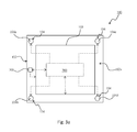
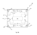
- Fig. 3a provides a plane view of the electronic device 100 looking at and/or through the first face 102a of the casing 102.
- the electronic device 100 can further include a processing portion 300.
- the casing 102 can be shaped and dimensioned to carry the processing portion 300.
- the processing portion 300 can be disposed within the casing 102.
- the processing portion 300 can be coupled to one or both of the display module 105 and the image capture module 106. Additionally, the image capture module 106 can be coupled to one or both of the display module 105 and the processing portion 300. Moreover, the photonic based detectors/sensors can be coupled to the processing portion 300 and/or the display module 105. The processing portion 300 can be further coupled to the audio output portions 104.
- the display module 105 can be configured to communicate input signals to the processing portion 300.
- the processing portion 300 can be configured to receive and process the input signals to produce output signals.
- the output signals can be communicated to the display module 105.
- the display module 105 can be further configured to display the output signals.
- the image capture module 106 can be configured to capture images and communicate image signals based on the captured images.
- Image signals can be communicated from the image capture module 106 to one or both of the display module 105 and the processing portion 300.
- Image signals can be communicated from the image capture module 106 to the display module 105 for display.
- Image signals can be communicated from the image capture module 106 to the processing portion 300 for further processing to produce processed image signals.
- Processed image signals can be communicated from the processing portion 300 to the display module 105 for display.
- the photonic based detectors/sensors can be configured to sense/detect optical signals such as IR signals.
- the photonic based detectors/sensors can be further configured to communicate the detected optical signals to one or both of the display module 105 and the processing portion 300.
- the optical signals can be communicated from the photonic based detectors/sensors to the processing portion 300 for processing to produce processed optical signals.
- the audio output portions 104 can, for example, include a first speaker driver 104a, a second speaker driver 104b, a third speaker driver 104c and a fourth speaker driver 104d.
- the processing portion 300 can be coupled to each of the first to fourth speaker drivers 104a/104b/104c/104d.
- the processing portion 300 can be configured to communicate audio signals to each or any combination of the first to fourth speaker drivers 104a/104b/104c/104d for output.
- the audio output portions 104 can be configured to output audio signals communicated from the processing portion 300 as will be discussed in further detail with reference to Fig. 3b and Fig. 3c .
- the electronic device 100 and the processing portion 300 will be shown in further detail with reference to Fig. 3b and Fig. 3c .
- the display module 105 will not be shown in Fig. 3b and Fig. 3c .
- the electronic device 100 can further include one or more enclosures 302.
- the casing 102 of the electronic device 100 can be shaped and dimensioned to carry one or more enclosures 302.
- the enclosures 302 can be formed within the casing 102.
- the casing 102 can be shaped and dimensioned in a manner so as to form the enclosures 302 within the casing 102.
- the number or enclosures 302 corresponds to the number of audio output portions 104.
- Each audio output portion 104 can be substantially enclosed/surrounded by an enclosure 302.
- the audio output portions 104 can include a first speaker driver 104a, a second speaker driver 104b, a third speaker driver 104c and a fourth speaker driver 104d.
- the number of audio output portions 104 is four. Therefore, there can be four enclosures 302.
- openings/perforations 202 can be arranged on the second face 102b based on the arrangement of the audio output portions 104.
- at least one opening/perforation 202 can be defined or provided within an enclosure 302.
- an opening/perforation 202 can be defined or provided in each of the aforementioned first enclosure to fourth enclosure 302a/302b/302c/302d.
- each enclosure 302 can be shaped and dimensioned in a manner so as to surround/enclose an audio output portion 104.
- the audio output portions 104 determine the arrangement of the one or more enclosures 302 within the casing 102.
- at least one opening/perforation can be defined or provided within each of the one or more enclosures 302. In this manner, the arrangement of the openings/perforations 202 on the second face 102b can be considered to be dependent on the arrangement of the audio output portions 104.
- the enclosures 302 and corresponding openings/perforations 202 can facilitate equalizing of pressure. Specifically pressure in the enclosures 302 can be equalized with respect to the environment (i.e., outside of the electronic device 100). This is made possible by the openings/perforations 202. Appreciably, to facilitate pressure equalizing, the openings/perforations 202 should not be substantially obstructed/blocked.
- protrusions 200 can extend from the second face 102b of the casing 102.
- the protrusions 200 can effectively elevate the electronic device 100 from the flat surface such that the openings/perforations 202 on the second face 102b are not covered/blocked by the flat surface. In this manner, the openings/perforations 202 remain substantially unobstructed even if the electronic device 100 is placed on a flat surface with the second face 102b facing the flat surface.
- audio output performance especially audio output performance of low frequency range audio signals (i.e., bass audio range)
- the enclosures 302 and perforations/openings 202 can function as some form of bass tuning to improve audio output performance of low frequency range audio signals.
- audio output performance, especially bass performance, of the electronic device 100 can be improved.
- Audio signals and frequency ranges i.e., low frequency range audio signals as mentioned above, mid frequency range audio signals and/or high frequency range audio signals associated with audio signals will be discussed later in further detail.
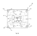
- Fig.3c shows the processing portion 300 in further detail.
- the processing portion 300 can include a sensor unit 304, a central processor unit 306, a storage unit 308 and an audio processor unit 310.
- the sensor unit 304 can be coupled to one or both of the central processor unit 306 and the audio processor unit 310.
- the central processor unit 306 can be coupled to one or both of the display module 105 and the image capture module 106.
- the central processor unit 306 can be further coupled to any of, or any combination of, the sensor unit 304, the storage unit 308, the audio processor unit 310 and the aforementioned one or more photonic based sensors/detectors.
- the storage unit 308 can be coupled to one or both of the central processor unit 306 and the audio processor unit 310.
- the audio processor unit 310 can be coupled to the audio output portions 104.
- the sensor unit 304 can be configured to sense/detect, for example, orientation and/or movement of the electronic device 100 as will be discussed later in further detail with reference to Fig. 4 .
- the sensor unit 304 can, for example, be a device such as a gyroscope, a digital compass or an accelerometer.
- the sensor unit 304 can, for example, correspond to one or more gyroscopes, one or more digital compasses and/or one or more accelerometers.
- the central processor unit 306 can be coupled to the display module 105 in a manner so as to receive input signals communicated from the display module 105.
- the central processor unit 306 can be further coupled to the image capture module 106 in a manner so as to receive image signals communicated from the image capture module 106.
- the central processor unit 306 can yet be further coupled to the sensor unit 304 in a manner so as to receive sensor signals communicated from the sensor unit 304.
- the central processor unit 306 can be coupled to the one or more photonic based sensors/detectors in a manner so as to receive optical signals detected by and communicated from the one or more photonic based sensors/detectors.
- the central processor portion 306 can be configured to process any one of, or any combination of, the input signals, image signals, sensor signals and optical signals to produce one or both of control signals and output signals.
- the central processor unit 306 can be further configured to process image signals and the optical signals to produce processed image signals and processed optical signals respectively.
- the output signals, the processed image signals and/or the processed optical signals can be communicated from the central processor unit 306 to the display module 105 for display.
- control signals can be communicated from the central processor unit 306 to any of the sensor unit 304, the storage unit 308 and the audio processor unit 310, or any combination thereof. Therefore control signals can be communicated from the central processor unit 306 to control the sensor unit 304, the storage unit 308 and/or the audio processor unit 310.
- control signals can be produced by the central processor unit 306 based on the input signals, the image signals, optical signals and/or the sensor signals.
- the storage unit 308 can be configured to store one or more electronic audio files such as MP3, MP4 and WMA based audio files.
- An audio file can be associated with audio signals having audio characteristics such as frequency characteristics and phase characteristics. Other examples of audio characteristics can include amplitude and channel characteristics.
- Frequency characteristics of an audio file can relate to the frequency of each audio signal associated with the audio file.
- an audio file can be associated with a plurality of frequency ranges.
- the plurality of frequency ranges can, for example, include low frequency range audio signals (e.g., between 20 Hz and 200 Hz), mid frequency range audio signals (e.g., between 201 Hz and 5 KHz) and/or high frequency range audio signals (e.g., between more than 5 KHz and 20 KHz).
- an audio signal when recorded, can be recorded in a manner such that it is more suitably audibly perceived by either the left ear of a user or a right ear of a user.
- an audio file may include audio signals that are more suitable for audio perception by the left ear of a user.
- An audio file may further include audio signals that are more suitable for audio perception by the right ear of the user.
- An audio file may yet further include audio signals that are suitable for audio perception by the left and right ears of a user. Therefore an audio signal can be associated with audio characteristics which may be indicative of appropriate channel output.
- channel characteristics of an audio signal can relate to appropriate channel output.
- a speaker system having at least a left channel speaker output and a right channel speaker output can be configured to output audio output signals based on an audio file.
- Audio signals associated with the audio file recorded to be more suitably perceived audibly by the left ear of a user can be associated with channel characteristics indicative that they should be more appropriately output via the left channel speaker output.
- Audio signals associated with the audio file recorded to be more suitably perceived audibly by the right ear of the user can be associated with channel characteristics indicative that they should be more appropriately output via the right channel speaker output.
- channel characteristics of audio signals can relate to at least of one of left channel output and right channel output.
- Left channel output can relate to the aforementioned output of audio signals via the left channel speaker output of a speaker system.
- Right channel output can relate to the aforementioned output of audio signals via the right channel speaker output of a speaker system.
- the storage unit 308 can be configured to communicate an electronic audio file to the audio processor unit 310 based on control signals received from the central processor unit 306.
- the storage unit 308 can be located in the electronic device 100 and/or in a remote location outside of the electronic device 100.
- electronic audio files can be communicated to the audio processor unit 310 from a remote location via a communication network.
- electronic audio files can be streamed from the internet.
- the storage unit 308 can be associated with Cloud based storage.
- the audio processor unit 310 can be configured to process the electronic audio file in a manner so as to produce audio output signals which can be communicated to and output at the audio output portions 104.
- audio processor unit 310 can be configured to receive audio signals associated with the audio file for processing to produce audio output signals. Therefore audio signals received by the audio processor unit 310 can be considered to be audio input signals. Thus audio input signals can be received and processed by the audio processor unit 310 to produce audio output signals.
- Audio input signals can, for example, be processed by the audio processor unit 310 such that audio characteristics of the audio input signals can be varied based on one or both of control signals and sensor signals as will be discussed later in further detail with reference to Fig. 4 .
- audio processor unit 310 any one of, or any combination of, frequency characteristics, phase characteristics and amplitude of audio input signals can be varied by the audio processor unit 310.
- the audio processor unit 310 can be further configured to vary/control output of the audio output signals based on one or both of control signals and sensor signals as will be discussed in further detail later with reference to Fig. 4 .
- output of the audio output signals can be varied/controlled in the context of directivity of output of the audio output signals.
- output of the audio output signals can be varied/controlled in the context of allowing and/or impeding output of audio output signals via at least a portion of the audio output portions 104.
- output of the audio output signals can be varied/controlled in the context of channel output of the audio output signals.
- output of the audio output signals can be varied/controlled in the context of directivity of output of the audio output signals, channel output of the audio output signals and allowing and/or impeding output of audio output signals via at least a portion of the audio output portions 104.
- Other examples include varying/controlling audio output signals in the context of three dimensional (3D) audio positioning on the output of the audio output signals.
- audio processor unit 310 The manner in which audio characteristics of the audio input signals can be varied, by the audio processor unit 310, based on one or both of control signals and sensor signals and/or the manner in which the audio processor unit 310 can be further configured to vary/control output of the audio output signals based on one or both of control signals and sensor signals will be discussed in further detail hereinafter with reference with Fig. 4 .
- Fig. 4a shows the electronic device 100 positioned in a first orientation 400a relative to a user 410.
- Fig. 4b shows the electronic device 100 positioned in a second orientation 400b relative to a user 410.
- the first orientation 400a can, for example, be a landscape orientation. Therefore, the electronic device 100 can be positioned in a landscape orientation relative to the user 410.
- the second orientation 400b can, for example, be a portrait orientation. Therefore, the electronic device 100 can be positioned in a portrait orientation relative to the user 410.
- the manner in which the audio processor unit 310 can be configured to vary/control output of the audio output signals based on one or both of control signals and sensor signals will be first discussed followed by the manner in which audio characteristics of the audio input signals can be varied, by the audio processor unit 310, based on one or both of control signals and sensor signals.
- output of the audio output signals can be varied/controlled in the context of:
- audio output signals can be output via the audio output portions 104 in a first set of directions 420 and a second set of directions 430 respectively.
- output of audio output signals based on the first orientation 400a and the second orientation 400b can be associated with a first set of directions 420 and a second set of directions 430 respectively.
- the first set of directions 420 and the second set of directions 430 can, for example, be such that audio signals are output from each of the first to fourth speaker drivers 104a/104b/104c/104d in a direction towards the user 410.
- Directivity of output of the audio output signals can correspond to output of the audio output signals in the first set of directions 420 and/or the second set of directions 430.
- the position of each of the first to fourth speaker drivers 104a/104b/104c/104d relative to the user 410 may be changed as compared to the position of each of the first to fourth speaker drivers 104a/104b/104c/104d relative to the user 410 when in the first orientation 400a.
- directivity of output of audio output signals from the first set of directions 420 to the second set of directions 430 can be considered to be varied/changed when the orientation of the electronic device 100 is changed from the first orientation 400a to the second orientation 400b.
- the first and third speaker drivers 104a/104c can be configured to output audio output signals away from the user 410.
- the second and fourth speaker drivers 104b/104d can be configured to output audio output signals toward the user 410.
- the first and second speaker drivers 104a/104b can be configured to output audio output signals away from the user 410 instead of the first and third speaker drivers 104a/104c when in the first orientation 400a.
- the third and fourth speaker drivers 104c/104d can be configured to output audio output signals toward the user 410 instead of the second and fourth speaker drivers 104b/104d when in the first orientation 400a.
- the first speaker driver 104a when the electronic device 100 is in the first orientation 400a, the first speaker driver 104a can be configured to output audio output signals at a direction towards a predetermined location which is a distance from the left of the user 410 and the third speaker driver 104c can be configured to output audio output signals at a direction towards a predetermined location which is a distance from the right of the user 410.
- the second and fourth speaker drivers 104b/104d can be configured to output audio output signals toward the user 410.
- the first speaker 104a can be configured to output audio output signals at a direction towards a predetermined location which is a distance from the right of the user 410 and the second speaker driver 104b can be configured to output audio output signals at a direction towards a predetermined location which is a distance from the left of the user 410.
- the third and fourth speaker drivers 104c/104d can be configured to output audio output signals toward the user 410.
- a speaker system having at least a left channel speaker output and a right channel speaker output can be configured to output audio output signals based on an audio file. Audio signals associated with the audio file recorded to be more suitably perceived audibly by the left ear of a user can be associated with channel characteristics indicative that they should be more appropriately output via the left channel speaker output.
- the audio output portions 104 of the electronic device 100 can be considered to be a speaker system.
- the first and second speaker drivers 104a/104b can be considered to be the aforementioned left channel speaker output.
- the third and fourth speaker drivers 104c/104d can be considered to be the aforementioned right channel speaker output.
- the second and fourth speaker drivers 104b/104d can be considered to be the aforementioned left channel speaker output.
- the first and third speaker drivers 104a/104c can be considered to be the aforementioned right channel speaker output.
- Audio input signals associable with left channel output audio characteristics can be processed by, for example, the audio processor unit 310 to produce audio output signals associable with left channel output audio characteristics.
- audio input signals associable with right channel output audio characteristics can be processed by, for example, the audio processor unit 310 to produce audio output signals associable with right channel output audio characteristics.
- audio output signals associable with left channel output audio characteristics can be output by the first speaker driver 104a and/or second speaker driver 104b. Additionally, audio output signals associable with right channel output audio characteristics can be output by the third speaker driver 104c and/or fourth speaker driver 104d.
- audio output signals associable with left channel output audio characteristics can be output by the second speaker driver 104b and/or fourth speaker driver 104d. Additionally, audio output signals associable with right channel output audio characteristics can be output by the first speaker driver 104a and/or third speaker driver 104c.
- a portion of the audio output portions 104 (e.g., the first speaker driver 104a and second speaker driver 104b) can be considered to be left channel speaker output and another portion of the audio output portions 104 (e.g., the third speaker driver 104c and fourth speaker driver 104d) can be considered to be right channel speaker output.
- a portion of the audio output portions 104 can be considered to be left channel speaker output and another portion of the audio output portions 104 (e.g., the first speaker driver 104a and third speaker driver 104c) can be considered to be right channel speaker output.
- the portion of audio output portions 104 considered to be left channel speaker output in the first orientation 400a and the portion of audio output portions 104 considered to be left channel speaker output in the second orientation 400b can be different.
- the portion of audio output portions 104 considered to be right channel speaker output in the first orientation 400a and the portion of audio output portions 104b considered to be right channel speaker output in the second orientation 400b can be different.
- audio output signals associable with left channel output audio characteristics can be output by the left channel speaker output regardless of change in orientation of the electronic device 100.
- audio output signals associable with right channel output audio characteristics can be output by the right channel speaker output regardless of change in orientation of the electronic device 100.
- the audio processor unit 310 can be configured in a manner so as to allow output of audio output signals associable with left channel output audio characteristics and audio output signals associable with right channel output audio characteristics by the aforementioned left channel speaker output and right channel speaker output respectively.
- At least a portion of the audio output portions 104 such as the first and third speaker drivers 104a/104c can be configured to allow output of only high and mid frequency range audio signals associated with an audio file. Additionally, at least a portion of the audio output portions 104 such as the second and fourth speaker drivers 104b/104d can be configured to impede output of high and mid frequency range audio signals and allow only output of low frequency range audio signals associated with an audio file.
- the first and second speaker drivers 104a/104b can be configured to allow output of only high and mid frequency range audio signals associated with an audio file instead of the first and third speaker drivers 104a/104c when in the first orientation 400a.
- the third and fourth speaker drivers 104c/104d can be configured to impede output of high and mid frequency range audio signals and allow only output of low frequency range audio signals associated with an audio file instead of the second and fourth speaker drivers 104b/104d when the electronic device 100 is in the first orientation 400a.
- control/vary output of audio output signals in the context of channel output of the audio output signals and/or control/vary output of audio output signals in the context of allowing and/or impeding output of audio output signals via at least a portion of the audio output portions 104 it is also possible to control/vary output of audio output signals in the context of 3D audio positioning on the output of the audio output signals.
- 3D audio positioning can be considered to be a group of sound processing algorithm which can manipulate audio image produced by the audio output portions 104. This may be related to virtual placement of sound sources in three dimensional space such as behind, below and/or above the user 410.
- the audio output portions 104 may be configured to output audio output signals in a manner such that the audio image produced can be audibly perceived by the user 410 to be above him/her (i.e., the user 410).
- the audio output portions 104 may be configured to output audio output signals in a manner such that the audio image produced can be audibly perceived by the user 410 to be below him/her (i.e., the user 410).
- Output of the audio output signals can be varied/controlled based on sensor signals communicated from the sensor unit 304.
- the sensor unit 304 can be configured to sense/detect change in orientation of the electronic device 100 and communicate sensor signals indicative of change in orientation of the electronic device 100.
- sensor signals can be communicated from the sensor unit 304 to the audio processor unit 310.
- the audio processor unit 310 can be configured to control/vary output of the audio output signals based on the sensor signals.
- output of the audio output signals can be varied/controlled based on control signals communicated from the central processor unit 306.
- sensor signals can be communicated from the sensor unit 304 to the central processor unit 306.
- the central processor unit 306 can be configured to receive and process the sensor signals to produce control signals which can be communicated to the audio processor unit 310.
- the audio processor unit 310 can be configured to control/vary output of the audio output signals based on the control signals.
- the control signals can be indicative of change in orientation of the electronic device 100.
- image signals can be communicated from the image capture module 106.
- Image signals can be based on captured images of one or more user gestures.
- the user 410 can, by waving his/her hand or moving his/her finger, provide a circular motion based gesture.
- the circular motion based gesture can, for example, be indicative of change in orientation of the electronic device 100.
- Image signals based on captured images of one or more user gestures such as the aforementioned circular motion based gesture can be communicated to the central processor unit 306 for processing to produce control signals.
- the control signals can be communicated to the audio processor unit 310.
- the audio processor unit 310 can be configured to control/vary output of the audio output signals based on the control signals.
- the audio processor unit 310 can be configured to control/vary output of the audio output signals based on the sensor signals and the control signals.
- controlling/varying output of audio output signals need not necessarily be based on physical positioning/physical change in orientation of the electronic device 100. Controlling/varying the output of audio output signals can also be possible even if the electronic device 100 remains stationary. For example, output of audio output signals can be varied/controlled based on captured images of one or more user gestures.
- audio characteristics of the audio input signals can be varied/controlled, by the audio processor unit 310, based on one or both of control signals and sensor signals.
- Audio characteristics can include any of, or any combination of, frequency characteristics, phase characteristics and amplitude.
- the audio output portions 104 can be calibrated prior to varying/controlling output of the audio output signals due to, for example, change in orientation/movement of the electronic device 100. Therefore the audio output portions can be initially calibrated prior to change in, for example, orientation/movement of the electronic device 100.
- the audio output portions 104 can be calibrated in a manner such that audio characteristics of audio output signals being output from each of the audio output portions 104 are substantially similar to audio characteristics of the audio input signals. Specifically, audio characteristics of the audio input signals remain substantially unchanged when they are output as audio output signals from each of the audio output portions.
- the audio output portions 104 can be calibrated in a manner so as to compensate/balance output of audio output signals.
- the audio output portions 104 can be calibrated to compensate, by manner of boosting, the loudness of the aforementioned right channel output so that the loudness of the left channel output and the right channel output can be audibly perceived to be balanced.
- the audio output portions 104 can be calibrated to compensate, by manner of attenuating, the loudness of the aforementioned left channel output so that the loudness of the left channel output and the right channel output can be audibly perceived to be balanced.
- calibrating the audio output portions 104 such that the frequency response of the left channel output and the frequency response of the right channel output are substantially similar initially (i.e., prior to, for example, change in orientation of the electronic device 100).
- the audio output portions 104 can generally be calibrated such that they can have an initial output response (i.e., initial frequency response/initial loudness etc) prior to, for example, change in orientation of the electronic device 100.
- calibrating the audio output portions 104 to compensate for difference in the shape/size of the enclosures 302. For example, there can be a difference in shape/size between the first enclosure 302a and the second enclosure 302b. Appreciably, the difference in shape and size may cause some variance in the aforementioned audio characteristics. By calibrating the audio output portions 104, such variance can be at least reduced or rendered insignificant/negligible.
- frequency characteristics of the audio input signals can be varied/controlled.
- the audio processor unit 310 can be configured to one or both of boost and attenuate signal amplitudes of low frequency range audio signals in a manner such that low frequency range audio output signals being output via the second and fourth speaker drivers 104b/104d can be boosted whereas low frequency range audio output signals being output via the first and third speaker drivers 104a/104c can be attenuated when the electronic device 100 is in the first orientation 400a.
- the audio processor unit 310 can be configured to one of boost and attenuate signal amplitudes of low frequency range audio signals in a manner such that low frequency range audio output signals being output via the third and fourth speaker drivers 104c/104d can be boosted whereas low frequency range audio output signals being output via the first and second speaker drivers 104a/104b can be attenuated.
- phase characteristics of the audio input signals can be varied/controlled.
- the audio processor unit 310 can be configured process audio input signals by phase shifting audio input signals such there is a phase shift between the audio output signals being output at the audio output portions 104.
- the audio processor unit 310 can be configured to process audio input signals by phase shifting audio input signals such that there is a, for example, 45 degree phase shift between the audio output signals being output via the first and second speaker drivers 104a/104b. Similarly, there can be, for example, a 45 degree phase shift between the audio output signals being output via the third and fourth speaker drivers 104c/104d when the electronic device 100 is in the first orientation 400a.
- the audio processor unit 310 can be configured to process audio input signals by phase shifting audio input signals such that there is a, for example, 90 degree phase shift between the audio output signals being output via the first and third speaker drivers 104a/104c. Similarly, there can be, for example, a 90 degree phase shift between the audio output signals being output via the second and fourth speaker drivers 104b/104d when the electronic device 100 is in the second orientation 400b.
- Controlling/varying audio characteristics of the audio input signals by the audio processor unit 310 based on one or both of control signals and sensor signals can be analogous to the earlier discussion regarding controlling/varying output of audio output signals based on one or both of control signals and sensor signals.
- the audio processor unit 310 can be configured to control/vary audio characteristics of audio input signals based on the sensor signals communicated from the sensor unit 304. In another example, the audio processor unit 310 can be configured to control/vary audio characteristics of audio input signals based on the control signals communicated from the central processor 306.
- controlling/varying audio characteristics of audio input signals need not necessarily be based on physical positioning/physical change in orientation of the electronic device 100. Controlling/varying the audio characteristics of audio input signals can also be possible even if the electronic device 100 remains stationary. For example, audio characteristics of audio input signals can be varied/controlled based on the aforementioned captured images of one or more user gestures.
- the electronic device 100 facilitates audio playback (i.e., output of audio output signals) in a substantially more user friendly and/or efficient manner as compared to conventional electronic audio reproduction device.
- audio playback i.e., output of audio output signals
- directivity of output of audio output signals from the electronic device 100 can be adjusted/varied/controlled based on one or both of the aforementioned control signals and sensor signals without having to manually adjust, for example, listening position of the user.
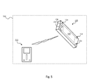
- an exemplary application 500 of the electronic device 100 is shown.
- another electronic device such as a media player device 510 can be coupled to the electronic device 100.
- the media player device 510 can be coupled to the electronic device 100 via one or both of wired coupling and wireless coupling.
- the media player device 510 can be configured to communicate audio signals to the electronic device 100.
- audio signals communicated from the media player device 510 can correspond to audio input signals.
- the electronic device 100 can be configured to receive and process the audio input signals so as to produce audio output signals.
- the audio output signals can be communicated to and output at the audio output portions 104.
- audio signals (corresponding to audio input signals) communicated from the media player device 510 can be received at and processed by the electronic device 100 to produce audio output signals which can be communicated to, and output at, the audio output portions 104.
- the electronic device 100 can be configured to receive and process audio signals communicated from the media player device 510 in a manner analogous to the earlier discussion(s) with reference to Fig. 3 and Fig.4 .
- the electronic device 100 can thus function as a portable speaker for another electronic device such as the aforementioned media player device 510.
- openings/perforations 202 can be arranged along the sides 102c of the casing 202 instead of at the second face 102b of the casing 102. Additionally openings/perforations 202 can optionally be arranged along the sides 102c and/or the second face 102b of the casing 202.
- output of the audio output signals can be varied/controlled in the context of time delay in the output of any of, or any combination of, the audio output portions 104.
- audio output signals can be output from each of the first to fourth speaker drivers 104a/104b/104c/104d at substantially the same time.
- output of audio output signals from the third and fourth speaker drivers 104c/104d can be delayed by a predetermined amount of time with respect to the first and second speaker drivers 104a/104b.
- the electronic device 100 can further include a delay module (not shown).
- the processing portion 300 can be coupled to the delay module.
- the delay module can be further coupled to the audio output portions 104. Based on one or both of control signals and sensor signals, the delay module can be configured to vary/control output of audio output signals in the context of time delay.
- controlling/varying output of audio output signals and/or audio characteristics of audio input signals can be further based on sound/voice control.
- the electronic device 100 can be configured to capture voice input of a user 410 using an audio detection unit (not shown) which can be coupled to the central processor unit 306.
- the audio detection unit can, for example, be a microphone. Captured voice input can be communicated as voice input signals to the central processor unit 306 for processing to produce control signals.
- the audio processor unit 310 can be configured to control/vary output of audio output signals and/or audio characteristics of audio input signals based on the control signals.
- the voice input signals can be communicated to the audio processor unit 310.
- the audio processor unit 310 can be configured to control/vary output of audio output signals and/or audio characteristics of audio input signals.
- first and second orientations 400a/400b are discussed in the context of changing orientation of the electronic device 100 between, for example, landscape orientation and portrait orientation, other situations such as tilting the electronic device 100 from an initial rest position can also be considered to be change in orientation.
- the electronic device 100 in an initial rest position can be considered to be a first orientation 400a.
- a user 410 can tilt the electronic device 100 up from its initial rest position such that the electronic device 100 is in a tilted position.
- the tilted position can be considered to be a second orientation 400b. Therefore, by titling the electronic device 100 from its initial rest position, orientation of the electronic device 100 can be considered to have changed from the first orientation 400a (i.e., initial rest position) to the second orientation 400b (i.e., tilted position).
- the sensor unit 304 can be configured to sense/detect change in orientation of the electronic device 100 and communicate sensor signals indicative of change in orientation of the electronic device 100, it can be appreciated that the sensor unit 304 can also be configured to sense/detect movement of the electronic device 100 and communicate sensor signals indicative of movement of the electronic device 100. Movement of the electronic device 100 can, for example, be lateral based movement.
- the user 410 can move the electronic device 100 between at least a first location and a second location. Specifically, the user 410 can, for example, move the electronic device 100 from a first location to a second location. More specifically, the user 410 can, for example, move the electronic device 100 from his/her left (i.e., first location) to his/her right (i.e., second location).
- the sensor unit 304 can be configured to sense/detect movement of the electronic device 100 from the left to the right of the user 410 and communicate sensor signals indicative of the movement of the electronic device 100 (i.e., from the left to the right of the user 410).
- the sensor signals can preferably be based upon to control/vary output of audio output signals from the audio output portions 104 and/or audio characteristics of the audio input signals.
- the sensor signals can be processed to produce control signals.
- Control signals and/or sensor signals can be based upon to control/vary output of audio output signals and/or audio characteristics of the audio input signals.
Landscapes
- Engineering & Computer Science (AREA)
- Theoretical Computer Science (AREA)
- Computer Hardware Design (AREA)
- Physics & Mathematics (AREA)
- Human Computer Interaction (AREA)
- General Engineering & Computer Science (AREA)
- General Physics & Mathematics (AREA)
- Health & Medical Sciences (AREA)
- Multimedia (AREA)
- Audiology, Speech & Language Pathology (AREA)
- General Health & Medical Sciences (AREA)
- Acoustics & Sound (AREA)
- Signal Processing (AREA)
- Circuit For Audible Band Transducer (AREA)
- Studio Devices (AREA)
- Stereophonic System (AREA)
- Telephone Function (AREA)
- Details Of Audible-Bandwidth Transducers (AREA)
Applications Claiming Priority (1)
| Application Number | Priority Date | Filing Date | Title |
|---|---|---|---|
| SG2012072146A SG2012072146A (en) | 2012-09-27 | 2012-09-27 | An electronic device |
Publications (3)
| Publication Number | Publication Date |
|---|---|
| EP2713267A2 true EP2713267A2 (de) | 2014-04-02 |
| EP2713267A3 EP2713267A3 (de) | 2014-07-09 |
| EP2713267B1 EP2713267B1 (de) | 2018-03-28 |
Family
ID=54256490
Family Applications (1)
| Application Number | Title | Priority Date | Filing Date |
|---|---|---|---|
| EP12192163.9A Not-in-force EP2713267B1 (de) | 2012-09-27 | 2012-11-12 | Steuerung der audiosignaleigenschaften einer elektronischen vorrichtung |
Country Status (5)
| Country | Link |
|---|---|
| US (1) | US9092197B2 (de) |
| EP (1) | EP2713267B1 (de) |
| CN (1) | CN103702273B (de) |
| SG (1) | SG2012072146A (de) |
| TW (1) | TWI566172B (de) |
Cited By (1)
| Publication number | Priority date | Publication date | Assignee | Title |
|---|---|---|---|---|
| EP3677052A4 (de) * | 2018-02-07 | 2020-10-14 | Samsung Electronics Co., Ltd. | Verfahren und elektronische vorrichtung zum abspielen von audiodaten unter verwendung eines doppelsprechers |
Families Citing this family (15)
| Publication number | Priority date | Publication date | Assignee | Title |
|---|---|---|---|---|
| US9432772B2 (en) * | 2012-11-08 | 2016-08-30 | Google Technology Holdings LLC | Methods and apparatus for porting loudspeakers to an earpiece |
| US9426573B2 (en) * | 2013-01-29 | 2016-08-23 | 2236008 Ontario Inc. | Sound field encoder |
| CN104427049A (zh) * | 2013-08-30 | 2015-03-18 | 深圳富泰宏精密工业有限公司 | 便携式电子装置 |
| US9671780B2 (en) | 2014-09-29 | 2017-06-06 | Sonos, Inc. | Playback device control |
| JP6459379B2 (ja) * | 2014-10-17 | 2019-01-30 | ヤマハ株式会社 | 音響システム |
| US20160112799A1 (en) * | 2014-10-17 | 2016-04-21 | Yamaha Corporation | Acoustic system, acoustic system control device, and acoustic system control method |
| US9681230B2 (en) * | 2014-10-17 | 2017-06-13 | Yamaha Corporation | Acoustic system, output device, and acoustic system control method |
| JP6380060B2 (ja) * | 2014-12-01 | 2018-08-29 | ヤマハ株式会社 | スピーカ装置 |
| US10805760B2 (en) * | 2015-07-23 | 2020-10-13 | Maxim Integrated Products, Inc. | Orientation aware audio soundstage mapping for a mobile device |
| WO2017091754A1 (en) * | 2015-11-25 | 2017-06-01 | Thomas Mitchell Dair | Surround sound applications and devices for vertically-oriented content |
| KR102733586B1 (ko) * | 2019-09-09 | 2024-11-22 | 삼성디스플레이 주식회사 | 표시 장치 |
| CN110657368B (zh) * | 2019-09-12 | 2025-03-28 | 东莞嘉盛照明科技有限公司 | 多功能音响橱柜灯 |
| WO2022119194A1 (ko) * | 2020-12-03 | 2022-06-09 | 삼성전자 주식회사 | 전자 장치 및 이를 이용한 멀티 채널 오디오 출력 방법 |
| KR102873561B1 (ko) | 2020-12-04 | 2025-10-21 | 삼성전자주식회사 | 플렉서블 디스플레이를 포함하는 전자 장치, 그 동작 방법 및 저장 매체 |
| CN120167116B (zh) * | 2024-12-20 | 2026-05-08 | 广州酷狗计算机科技有限公司 | 音频处理方法、装置、设备及存储介质 |
Family Cites Families (15)
| Publication number | Priority date | Publication date | Assignee | Title |
|---|---|---|---|---|
| GB2347593B (en) * | 1999-01-06 | 2001-05-23 | Motorola Inc | Apparatus and method for using motion to input information to a wireless communication device |
| GB2359177A (en) * | 2000-02-08 | 2001-08-15 | Nokia Corp | Orientation sensitive display and selection mechanism |
| US8600084B1 (en) * | 2004-11-09 | 2013-12-03 | Motion Computing, Inc. | Methods and systems for altering the speaker orientation of a portable system |
| JP2006174277A (ja) * | 2004-12-17 | 2006-06-29 | Casio Hitachi Mobile Communications Co Ltd | 携帯端末、ステレオ再生方法およびステレオ再生プログラム |
| TWI327286B (en) * | 2005-09-30 | 2010-07-11 | Hon Hai Prec Ind Co Ltd | Apparatus and method for displaying an ellipse-type menu |
| US8676713B2 (en) * | 2006-05-30 | 2014-03-18 | Dell Products L.P. | Dynamic constraints for content rights |
| TWM303429U (en) * | 2006-06-20 | 2006-12-21 | Action Electronics Co Ltd | Operating system comprising a touch-controlled interface |
| TWI382737B (zh) * | 2008-07-08 | 2013-01-11 | Htc Corp | 手持電子裝置及其操作方法 |
| US20100008523A1 (en) * | 2008-07-14 | 2010-01-14 | Sony Ericsson Mobile Communications Ab | Handheld Devices Including Selectively Enabled Audio Transducers |
| US20110002487A1 (en) * | 2009-07-06 | 2011-01-06 | Apple Inc. | Audio Channel Assignment for Audio Output in a Movable Device |
| US20110150247A1 (en) * | 2009-12-17 | 2011-06-23 | Rene Martin Oliveras | System and method for applying a plurality of input signals to a loudspeaker array |
| CA2785080C (en) * | 2009-12-24 | 2017-01-17 | Nokia Corporation | An apparatus |
| US20110316768A1 (en) * | 2010-06-28 | 2011-12-29 | Vizio, Inc. | System, method and apparatus for speaker configuration |
| US9253561B2 (en) * | 2011-04-14 | 2016-02-02 | Bose Corporation | Orientation-responsive acoustic array control |
| KR20130016906A (ko) * | 2011-08-09 | 2013-02-19 | 삼성전자주식회사 | 전자 장치 및 스테레오 사운드 제공방법 |
-
2012
- 2012-09-27 SG SG2012072146A patent/SG2012072146A/en unknown
- 2012-10-15 TW TW101137895A patent/TWI566172B/zh not_active IP Right Cessation
- 2012-10-19 US US13/656,553 patent/US9092197B2/en active Active
- 2012-11-12 EP EP12192163.9A patent/EP2713267B1/de not_active Not-in-force
- 2012-11-20 CN CN201210472823.5A patent/CN103702273B/zh not_active Expired - Fee Related
Cited By (1)
| Publication number | Priority date | Publication date | Assignee | Title |
|---|---|---|---|---|
| EP3677052A4 (de) * | 2018-02-07 | 2020-10-14 | Samsung Electronics Co., Ltd. | Verfahren und elektronische vorrichtung zum abspielen von audiodaten unter verwendung eines doppelsprechers |
Also Published As
| Publication number | Publication date |
|---|---|
| SG2012072146A (en) | 2014-04-28 |
| CN103702273A (zh) | 2014-04-02 |
| CN103702273B (zh) | 2018-03-20 |
| EP2713267B1 (de) | 2018-03-28 |
| US9092197B2 (en) | 2015-07-28 |
| TWI566172B (zh) | 2017-01-11 |
| EP2713267A3 (de) | 2014-07-09 |
| US20140086415A1 (en) | 2014-03-27 |
| TW201413579A (zh) | 2014-04-01 |
Similar Documents
| Publication | Publication Date | Title |
|---|---|---|
| EP2713235B1 (de) | Elektronische Vorrichtung | |
| EP2713267B1 (de) | Steuerung der audiosignaleigenschaften einer elektronischen vorrichtung | |
| US12238488B2 (en) | Systems and methods for equalizing audio for playback on an electronic device | |
| US11089144B2 (en) | Head-mounted display apparatus for retaining a portable electronic device with display | |
| EP3048804B1 (de) | Kopfhörer mit integraler bildanzeige | |
| JP2022547251A (ja) | 周辺を包囲する音声溝および音響ポートを含む表示デバイス | |
| CN109524016B (zh) | 音频处理方法、装置、电子设备及存储介质 | |
| JP7739504B2 (ja) | ディスプレイ装置及びその動作方法 | |
| KR20220043000A (ko) | 사운드박스 어셈블리, 디스플레이 장치, 오디오 출력 방법 및 장치 | |
| WO2008017905A2 (en) | Hand-held electronic device | |
| CN109360582B (zh) | 音频处理方法、装置及存储介质 | |
| KR20140121694A (ko) | 촬영 장치 및 촬영 제어 방법 | |
| WO2018042658A1 (ja) | 携帯情報端末、頭部装着表示システム、及びその音声出力制御方法 | |
| KR102307453B1 (ko) | 듀얼 패널 오디오 액추에이터 및 이를 포함하는 이동 장치 |
Legal Events
| Date | Code | Title | Description |
|---|---|---|---|
| PUAI | Public reference made under article 153(3) epc to a published international application that has entered the european phase |
Free format text: ORIGINAL CODE: 0009012 |
|
| AK | Designated contracting states |
Kind code of ref document: A2 Designated state(s): AL AT BE BG CH CY CZ DE DK EE ES FI FR GB GR HR HU IE IS IT LI LT LU LV MC MK MT NL NO PL PT RO RS SE SI SK SM TR |
|
| AX | Request for extension of the european patent |
Extension state: BA ME |
|
| PUAL | Search report despatched |
Free format text: ORIGINAL CODE: 0009013 |
|
| AK | Designated contracting states |
Kind code of ref document: A3 Designated state(s): AL AT BE BG CH CY CZ DE DK EE ES FI FR GB GR HR HU IE IS IT LI LT LU LV MC MK MT NL NO PL PT RO RS SE SI SK SM TR |
|
| AX | Request for extension of the european patent |
Extension state: BA ME |
|
| RIC1 | Information provided on ipc code assigned before grant |
Ipc: G06F 3/16 20060101AFI20140603BHEP Ipc: G06F 1/16 20060101ALI20140603BHEP |
|
| 17P | Request for examination filed |
Effective date: 20150106 |
|
| RBV | Designated contracting states (corrected) |
Designated state(s): AL AT BE BG CH CY CZ DE DK EE ES FI FR GB GR HR HU IE IS IT LI LT LU LV MC MK MT NL NO PL PT RO RS SE SI SK SM TR |
|
| STAA | Information on the status of an ep patent application or granted ep patent |
Free format text: STATUS: EXAMINATION IS IN PROGRESS |
|
| RIC1 | Information provided on ipc code assigned before grant |
Ipc: H04R 5/04 20060101ALI20170209BHEP Ipc: G06F 3/16 20060101AFI20170209BHEP Ipc: G06F 1/16 20060101ALI20170209BHEP |
|
| 17Q | First examination report despatched |
Effective date: 20170301 |
|
| GRAP | Despatch of communication of intention to grant a patent |
Free format text: ORIGINAL CODE: EPIDOSNIGR1 |
|
| STAA | Information on the status of an ep patent application or granted ep patent |
Free format text: STATUS: GRANT OF PATENT IS INTENDED |
|
| INTG | Intention to grant announced |
Effective date: 20171110 |
|
| GRAS | Grant fee paid |
Free format text: ORIGINAL CODE: EPIDOSNIGR3 |
|
| GRAA | (expected) grant |
Free format text: ORIGINAL CODE: 0009210 |
|
| STAA | Information on the status of an ep patent application or granted ep patent |
Free format text: STATUS: THE PATENT HAS BEEN GRANTED |
|
| AK | Designated contracting states |
Kind code of ref document: B1 Designated state(s): AL AT BE BG CH CY CZ DE DK EE ES FI FR GB GR HR HU IE IS IT LI LT LU LV MC MK MT NL NO PL PT RO RS SE SI SK SM TR |
|
| REG | Reference to a national code |
Ref country code: GB Ref legal event code: FG4D |
|
| REG | Reference to a national code |
Ref country code: CH Ref legal event code: EP |
|
| REG | Reference to a national code |
Ref country code: AT Ref legal event code: REF Ref document number: 984001 Country of ref document: AT Kind code of ref document: T Effective date: 20180415 |
|
| REG | Reference to a national code |
Ref country code: IE Ref legal event code: FG4D |
|
| REG | Reference to a national code |
Ref country code: DE Ref legal event code: R096 Ref document number: 602012044425 Country of ref document: DE |
|
| REG | Reference to a national code |
Ref country code: NL Ref legal event code: FP |
|
| PG25 | Lapsed in a contracting state [announced via postgrant information from national office to epo] |
Ref country code: LT Free format text: LAPSE BECAUSE OF FAILURE TO SUBMIT A TRANSLATION OF THE DESCRIPTION OR TO PAY THE FEE WITHIN THE PRESCRIBED TIME-LIMIT Effective date: 20180328 Ref country code: NO Free format text: LAPSE BECAUSE OF FAILURE TO SUBMIT A TRANSLATION OF THE DESCRIPTION OR TO PAY THE FEE WITHIN THE PRESCRIBED TIME-LIMIT Effective date: 20180628 Ref country code: HR Free format text: LAPSE BECAUSE OF FAILURE TO SUBMIT A TRANSLATION OF THE DESCRIPTION OR TO PAY THE FEE WITHIN THE PRESCRIBED TIME-LIMIT Effective date: 20180328 Ref country code: FI Free format text: LAPSE BECAUSE OF FAILURE TO SUBMIT A TRANSLATION OF THE DESCRIPTION OR TO PAY THE FEE WITHIN THE PRESCRIBED TIME-LIMIT Effective date: 20180328 |
|
| REG | Reference to a national code |
Ref country code: LT Ref legal event code: MG4D |
|
| PG25 | Lapsed in a contracting state [announced via postgrant information from national office to epo] |
Ref country code: GR Free format text: LAPSE BECAUSE OF FAILURE TO SUBMIT A TRANSLATION OF THE DESCRIPTION OR TO PAY THE FEE WITHIN THE PRESCRIBED TIME-LIMIT Effective date: 20180629 Ref country code: LV Free format text: LAPSE BECAUSE OF FAILURE TO SUBMIT A TRANSLATION OF THE DESCRIPTION OR TO PAY THE FEE WITHIN THE PRESCRIBED TIME-LIMIT Effective date: 20180328 Ref country code: BG Free format text: LAPSE BECAUSE OF FAILURE TO SUBMIT A TRANSLATION OF THE DESCRIPTION OR TO PAY THE FEE WITHIN THE PRESCRIBED TIME-LIMIT Effective date: 20180628 Ref country code: SE Free format text: LAPSE BECAUSE OF FAILURE TO SUBMIT A TRANSLATION OF THE DESCRIPTION OR TO PAY THE FEE WITHIN THE PRESCRIBED TIME-LIMIT Effective date: 20180328 Ref country code: RS Free format text: LAPSE BECAUSE OF FAILURE TO SUBMIT A TRANSLATION OF THE DESCRIPTION OR TO PAY THE FEE WITHIN THE PRESCRIBED TIME-LIMIT Effective date: 20180328 |
|
| PG25 | Lapsed in a contracting state [announced via postgrant information from national office to epo] |
Ref country code: IT Free format text: LAPSE BECAUSE OF FAILURE TO SUBMIT A TRANSLATION OF THE DESCRIPTION OR TO PAY THE FEE WITHIN THE PRESCRIBED TIME-LIMIT Effective date: 20180328 Ref country code: RO Free format text: LAPSE BECAUSE OF FAILURE TO SUBMIT A TRANSLATION OF THE DESCRIPTION OR TO PAY THE FEE WITHIN THE PRESCRIBED TIME-LIMIT Effective date: 20180328 Ref country code: AL Free format text: LAPSE BECAUSE OF FAILURE TO SUBMIT A TRANSLATION OF THE DESCRIPTION OR TO PAY THE FEE WITHIN THE PRESCRIBED TIME-LIMIT Effective date: 20180328 Ref country code: PL Free format text: LAPSE BECAUSE OF FAILURE TO SUBMIT A TRANSLATION OF THE DESCRIPTION OR TO PAY THE FEE WITHIN THE PRESCRIBED TIME-LIMIT Effective date: 20180328 Ref country code: ES Free format text: LAPSE BECAUSE OF FAILURE TO SUBMIT A TRANSLATION OF THE DESCRIPTION OR TO PAY THE FEE WITHIN THE PRESCRIBED TIME-LIMIT Effective date: 20180328 Ref country code: EE Free format text: LAPSE BECAUSE OF FAILURE TO SUBMIT A TRANSLATION OF THE DESCRIPTION OR TO PAY THE FEE WITHIN THE PRESCRIBED TIME-LIMIT Effective date: 20180328 |
|
| PG25 | Lapsed in a contracting state [announced via postgrant information from national office to epo] |
Ref country code: SM Free format text: LAPSE BECAUSE OF FAILURE TO SUBMIT A TRANSLATION OF THE DESCRIPTION OR TO PAY THE FEE WITHIN THE PRESCRIBED TIME-LIMIT Effective date: 20180328 Ref country code: CZ Free format text: LAPSE BECAUSE OF FAILURE TO SUBMIT A TRANSLATION OF THE DESCRIPTION OR TO PAY THE FEE WITHIN THE PRESCRIBED TIME-LIMIT Effective date: 20180328 Ref country code: SK Free format text: LAPSE BECAUSE OF FAILURE TO SUBMIT A TRANSLATION OF THE DESCRIPTION OR TO PAY THE FEE WITHIN THE PRESCRIBED TIME-LIMIT Effective date: 20180328 |
|
| REG | Reference to a national code |
Ref country code: AT Ref legal event code: MK05 Ref document number: 984001 Country of ref document: AT Kind code of ref document: T Effective date: 20180328 |
|
| PG25 | Lapsed in a contracting state [announced via postgrant information from national office to epo] |
Ref country code: PT Free format text: LAPSE BECAUSE OF FAILURE TO SUBMIT A TRANSLATION OF THE DESCRIPTION OR TO PAY THE FEE WITHIN THE PRESCRIBED TIME-LIMIT Effective date: 20180730 |
|
| REG | Reference to a national code |
Ref country code: DE Ref legal event code: R097 Ref document number: 602012044425 Country of ref document: DE |
|
| PG25 | Lapsed in a contracting state [announced via postgrant information from national office to epo] |
Ref country code: AT Free format text: LAPSE BECAUSE OF FAILURE TO SUBMIT A TRANSLATION OF THE DESCRIPTION OR TO PAY THE FEE WITHIN THE PRESCRIBED TIME-LIMIT Effective date: 20180328 Ref country code: DK Free format text: LAPSE BECAUSE OF FAILURE TO SUBMIT A TRANSLATION OF THE DESCRIPTION OR TO PAY THE FEE WITHIN THE PRESCRIBED TIME-LIMIT Effective date: 20180328 |
|
| PLBE | No opposition filed within time limit |
Free format text: ORIGINAL CODE: 0009261 |
|
| STAA | Information on the status of an ep patent application or granted ep patent |
Free format text: STATUS: NO OPPOSITION FILED WITHIN TIME LIMIT |
|
| 26N | No opposition filed |
Effective date: 20190103 |
|
| PG25 | Lapsed in a contracting state [announced via postgrant information from national office to epo] |
Ref country code: SI Free format text: LAPSE BECAUSE OF FAILURE TO SUBMIT A TRANSLATION OF THE DESCRIPTION OR TO PAY THE FEE WITHIN THE PRESCRIBED TIME-LIMIT Effective date: 20180328 |
|
| REG | Reference to a national code |
Ref country code: CH Ref legal event code: PL |
|
| PG25 | Lapsed in a contracting state [announced via postgrant information from national office to epo] |
Ref country code: LU Free format text: LAPSE BECAUSE OF NON-PAYMENT OF DUE FEES Effective date: 20181112 Ref country code: MC Free format text: LAPSE BECAUSE OF FAILURE TO SUBMIT A TRANSLATION OF THE DESCRIPTION OR TO PAY THE FEE WITHIN THE PRESCRIBED TIME-LIMIT Effective date: 20180328 |
|
| REG | Reference to a national code |
Ref country code: BE Ref legal event code: MM Effective date: 20181130 |
|
| REG | Reference to a national code |
Ref country code: IE Ref legal event code: MM4A |
|
| PG25 | Lapsed in a contracting state [announced via postgrant information from national office to epo] |
Ref country code: CH Free format text: LAPSE BECAUSE OF NON-PAYMENT OF DUE FEES Effective date: 20181130 Ref country code: LI Free format text: LAPSE BECAUSE OF NON-PAYMENT OF DUE FEES Effective date: 20181130 |
|
| PG25 | Lapsed in a contracting state [announced via postgrant information from national office to epo] |
Ref country code: IE Free format text: LAPSE BECAUSE OF NON-PAYMENT OF DUE FEES Effective date: 20181112 |
|
| PG25 | Lapsed in a contracting state [announced via postgrant information from national office to epo] |
Ref country code: BE Free format text: LAPSE BECAUSE OF NON-PAYMENT OF DUE FEES Effective date: 20181130 |
|
| PG25 | Lapsed in a contracting state [announced via postgrant information from national office to epo] |
Ref country code: MT Free format text: LAPSE BECAUSE OF NON-PAYMENT OF DUE FEES Effective date: 20181112 |
|
| PG25 | Lapsed in a contracting state [announced via postgrant information from national office to epo] |
Ref country code: TR Free format text: LAPSE BECAUSE OF FAILURE TO SUBMIT A TRANSLATION OF THE DESCRIPTION OR TO PAY THE FEE WITHIN THE PRESCRIBED TIME-LIMIT Effective date: 20180328 |
|
| PG25 | Lapsed in a contracting state [announced via postgrant information from national office to epo] |
Ref country code: MK Free format text: LAPSE BECAUSE OF NON-PAYMENT OF DUE FEES Effective date: 20180328 Ref country code: CY Free format text: LAPSE BECAUSE OF FAILURE TO SUBMIT A TRANSLATION OF THE DESCRIPTION OR TO PAY THE FEE WITHIN THE PRESCRIBED TIME-LIMIT Effective date: 20180328 Ref country code: HU Free format text: LAPSE BECAUSE OF FAILURE TO SUBMIT A TRANSLATION OF THE DESCRIPTION OR TO PAY THE FEE WITHIN THE PRESCRIBED TIME-LIMIT; INVALID AB INITIO Effective date: 20121112 |
|
| PG25 | Lapsed in a contracting state [announced via postgrant information from national office to epo] |
Ref country code: IS Free format text: LAPSE BECAUSE OF FAILURE TO SUBMIT A TRANSLATION OF THE DESCRIPTION OR TO PAY THE FEE WITHIN THE PRESCRIBED TIME-LIMIT Effective date: 20180728 |
|
| P01 | Opt-out of the competence of the unified patent court (upc) registered |
Effective date: 20230520 |
|
| PGFP | Annual fee paid to national office [announced via postgrant information from national office to epo] |
Ref country code: NL Payment date: 20231126 Year of fee payment: 12 |
|
| PGFP | Annual fee paid to national office [announced via postgrant information from national office to epo] |
Ref country code: GB Payment date: 20231127 Year of fee payment: 12 |
|
| PGFP | Annual fee paid to national office [announced via postgrant information from national office to epo] |
Ref country code: FR Payment date: 20231127 Year of fee payment: 12 Ref country code: DE Payment date: 20231129 Year of fee payment: 12 |
|
| REG | Reference to a national code |
Ref country code: DE Ref legal event code: R119 Ref document number: 602012044425 Country of ref document: DE |
|
| REG | Reference to a national code |
Ref country code: NL Ref legal event code: MM Effective date: 20241201 |
|
| GBPC | Gb: european patent ceased through non-payment of renewal fee |
Effective date: 20241112 |
|
| PG25 | Lapsed in a contracting state [announced via postgrant information from national office to epo] |
Ref country code: NL Free format text: LAPSE BECAUSE OF NON-PAYMENT OF DUE FEES Effective date: 20241201 |
|
| PG25 | Lapsed in a contracting state [announced via postgrant information from national office to epo] |
Ref country code: DE Free format text: LAPSE BECAUSE OF NON-PAYMENT OF DUE FEES Effective date: 20250603 |
|
| PG25 | Lapsed in a contracting state [announced via postgrant information from national office to epo] |
Ref country code: GB Free format text: LAPSE BECAUSE OF NON-PAYMENT OF DUE FEES Effective date: 20241112 |
|
| PG25 | Lapsed in a contracting state [announced via postgrant information from national office to epo] |
Ref country code: FR Free format text: LAPSE BECAUSE OF NON-PAYMENT OF DUE FEES Effective date: 20241130 |