EP2713471B1 - Ladegerät - Google Patents
Ladegerät Download PDFInfo
- Publication number
- EP2713471B1 EP2713471B1 EP12196249.2A EP12196249A EP2713471B1 EP 2713471 B1 EP2713471 B1 EP 2713471B1 EP 12196249 A EP12196249 A EP 12196249A EP 2713471 B1 EP2713471 B1 EP 2713471B1
- Authority
- EP
- European Patent Office
- Prior art keywords
- fitting portion
- coupling
- indentation
- electrical connector
- supporting
- Prior art date
- Legal status (The legal status is an assumption and is not a legal conclusion. Google has not performed a legal analysis and makes no representation as to the accuracy of the status listed.)
- Active
Links
Images



Classifications
-
- H—ELECTRICITY
- H02—GENERATION; CONVERSION OR DISTRIBUTION OF ELECTRIC POWER
- H02J—ELECTRIC POWER NETWORKS; CIRCUIT ARRANGEMENTS OR SYSTEMS FOR SUPPLYING OR DISTRIBUTING ELECTRIC POWER; SYSTEMS FOR STORING ELECTRIC ENERGY
- H02J7/00—Circuit arrangements for charging or discharging batteries or for supplying loads from batteries
- H02J7/70—Circuit arrangements for charging or discharging batteries or for supplying loads from batteries characterised by the mechanical construction
- H02J7/731—Circuit arrangements for charging or discharging batteries or for supplying loads from batteries characterised by the mechanical construction specially adapted for holding portable devices containing batteries
Definitions
- the disclosure relates to a charger, and more particularly to a charger with changeable supporting stands with different standards.
- the portable electronic products include products such as mobile phone, tablet computer, portable computer, portable scanner and digital camera, etc.
- the portable electronic products are not equipped with charging sockets so the portable electronic products have to be charged by using chargers.
- the multiple portable electronic products are different in shapes and standards because there are different brands, different types and models, and furthermore the chargers, produced by different manufacturers, are usually used for electronic products of specific models, a user will have to purchase multiple chargers corresponding to the electronic products which the user owns. In other words, the electronic products cannot share the same charger and the users are therefore forced to purchase different chargers for charging different corresponding electronic products.
- the user wants to go on a journey he/she will have to bring the multiple chargers for the electronic products in order to ensure that the electronic products can be charged if they run out of power.
- the charger can comprise a battery box detachably connected with a dock for accommodating and charging a battery therein.
- the fixation structure of the battery box which is used for connecting the charger is not well designed such that it is inconvenient for attachment and detachment of them.
- EP 2 182 608 A2 , US 5 926 005 A , DE 27 02 129 A1 , EP2 315 322 A1 , WO 2007/102997 A2 , US 6 049 192 A and US 5 256 955 A Therefore, it is highly demanded for developing a charger for charging various electronic products.
- a charger provided in an embodiment of the disclosure comprises a base and a charging circuit.
- the base comprises a coupling portion for detachably coupling with one of a plurality of supporting stands.
- Each of the supporting stands has a supporting container with different standards.
- the coupling portion has a coupling surface.
- the coupling surface is used for supporting one of the supporting stands.
- the charging circuit is disposed in the base and the charging circuit has a first electrical connector. The first electrical connector protrudes from the coupling surface. When the coupling portion is coupled with the supporting stand, a portion of the first electrical connector is disposed in the supporting container.
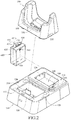
- FIG. 1 is a perspective view of a charger according to an embodiment of the disclosure
- Fig. 2 is an exploded perspective view of Fig. 1
- a charger 10 of this embodiment has a plug (not shown in the drawings) for connecting with a socket, and electronic products may be charged through the charger 10.
- the electronic products may be products such as portable computer, portable scanner, tablet computer and mobile phone.
- the mobile phone is used for the electronic product in this embodiment, but not limited to the disclosure.
- the charger 10 in this embodiment comprises a base 100 and a charging circuit 200, multiple supporting stands 300 and multiple battery boxes 400.
- the base 100 comprises a coupling portion 110.
- the coupling portion 110 has a coupling surface 111.
- the coupling surface 111 is used for supporting one of multiple supporting stands 300.
- the coupling portion 110 is used for detachably coupling with one of the supporting stands 300.
- Each of the supporting stands 300 has a supporting container 310 which have different standards with each other.
- Each of the supporting stands 300 has a slot 320 disposed on a bottom of the supporting container 310 as well as corresponding to the supporting container 310.
- the charging circuit 200 is disposed in the base 100.
- the charging circuit 200 has a first electrical connector 210.
- the first electrical connector 210 protrudes from the coupling surface 111.
- the coupling portion 110 is coupled with the supporting stand 300, the first electrical connector 210 penetrates through the slot 320 such that a portion of the first electrical connector 210 is disposed in the supporting container 310. Therefore, a user can place an electronic product matching the standards of the supporting container 310 on the supporting stand 300 for charging the electronic product.
- the coupling portion 110 comprises two fastening pieces 120.
- the two fastening pieces 120 are disposed on two opposite sides of the coupling surface 111, respectively.
- the supporting stand 300 comprises two fastening indentations 330 disposed on two opposite sides of the supporting stand 300, respectively.
- the two fastening pieces 120 may be detachably fastened with the two fastening indentations 330 correspondingly such that the supporting stand 300 may be detachably fastened on the base 100.
- the user can substitute the supporting stand 300 rapidly with the above-mentioned fastening mechanism between the fastening pieces 120 and the fastening indentations 330.
- the base 100 further comprises a coupling indentation 130 and an upper surface 140.
- the upper surface 140 is connected with the circumference of the coupling indentation 130.
- the coupling indentation 130 is used for being coupled with one of multiple battery boxes 400.
- the charging circuit 200 further comprises a second electrical connector 220 disposed in the coupling indentation 130.
- the battery boxes 400 may be detachably installed in the coupling indentation 130.
- Each of the battery boxes 400 has an accommodating indentation 410 and a third electrical connector 440.
- the accommodating indentation 410 is used for accommodating at least one battery 30.
- the third electrical connector 440 is disposed in the accommodating indentation 410 for electrically connecting with the battery 30.
- the third electrical connector 440 is partially exposed outside the accommodating indentation 410. Therefore, when the battery box 400 is detachably installed in the coupling indentation 130, the third electrical connector 440 may be detachably and electrically connected with the second electrical connector 220.
- Each of the battery boxes 400 comprises a first fitting portion 420 and a second fitting portion 430.
- the first fitting portion 420 and the second fitting portion 430 are disposed on two opposite sides of the battery box 400, respectively.
- the base 100 comprises a third fitting portion 150 and a fourth fitting portion 160.
- the third fitting portion 150 and the fourth fitting portion 160 are disposed on two opposite sides of the coupling indentation 130, respectively.
- the first fitting portion 420 is a convex-shaped block
- the third fitting portion 150 is a concave indentation whose shape matches with that of the convex-shaped block.
- the second fitting portion 430 comprises an elastic piece 431 and a convex-shaped block 432.
- the elastic piece 431 has a fastening section 431 a and a releasing section 431b.
- the fastening section 431a and the releasing section 431b are connected with each other.
- the fastening section 431a is connected with the battery box 400, and the fastening section 431a is positioned between the battery box 400 and the base 100.
- the convex-shaped block 432 is disposed on a surface of the fastening section 431a facing the coupling indentation 130. A portion of the releasing section 431b protrudes from the upper surface 140.
- the fourth fitting portion 160 is a concave indentation corresponding to the convex-shaped block 432.
- the convex-shaped block 432 faces the fourth fitting portion 160, and the convex-shaped block 432 is normally fastened with the fourth fitting portion 160 by the elastic piece 431.
- the user can press the releasing section 431b to make the convex-shaped block 432 move relatively further away from the fourth fitting portion 160 in order to detach the battery box 400 from the coupling indentation 130. Therefore, the battery box 400 with other standards may be substituted later.
- Figs. 3A to 3C are usage illustrations of Fig. 1 .
- the electronic product 20 When an electronic product 20 needs to be charged, the electronic product 20 is placed in the supporting container 310 of the supporting stand 300 whose shape matches with that of the electronic product 20 such that the electronic product 20 is electrically connected with the first electrical connector 210 as shown in Fig. 3A .
- the user When another electronic product 20' needs to be charged, the user simply substitutes another supporting stand 300' including a supporting container 310' with other standards on a base 100' (as shown in Fig. 3B ) for the previous supporting stand 300 in order to charge another electronic product 20' (as shown in Fig. 3C ).
- the charger 10 of the embodiment in Fig. 1 is applicable for situations which the shapes of various electronic products are different and the types of the electrical connectors of various electronic products are the same, but not limited to the disclosure. In other embodiments, the charger 10 is also applicable for situations which both the shapes of various electronic products and the types of the electrical connectors are different.
- Fig. 4 is an exploded perspective view of the charger according to another embodiment of the disclosure.
- the charger 10 of this embodiment comprises a base 100, a charging circuit 200, a supporting stand 300 and a battery box 400.
- the charging circuit 200 is disposed in the base 100.
- the charging circuit 200 has a first electrical connector 210 which is disposed outside the base 100.
- the supporting stand 300 and the battery box 400 may be detachably installed on the base 100.
- the supporting stand 300 has an adaptor 340.
- the adaptor 340 is an electrical connector, and the standards of the adaptor 340 are different from those of the first electrical connector 210. Therefore, the standards of the electrical connector are also substituted while the user substitute the supporting stand 300 in the mean time, and an electronic product including an electrical connector with different standards may be charged.
- the charger by using the coupling portion of the case for detachably coupling with one of the supporting stands with different standards, the charger can be used for charging various electronic products by substituting the supporting stand.
- the charger can be used for charging various batteries by changing the battery boxes.
Landscapes
- Engineering & Computer Science (AREA)
- Power Engineering (AREA)
- Charge And Discharge Circuits For Batteries Or The Like (AREA)
- Telephone Set Structure (AREA)
Claims (3)
- Ladegerät (10) gekennzeichnet durch:eine Basis (100) mit einer Oberseite (140), umfassend einen Kupplungsbereich (110), eine Kupplungsvertiefung (130), eine Mehrzahl an Abstützständern (300) und eins von einer Mehrzahl an Batteriegehäusen (400), wobei der Kupplungsbereich (110) lösbar kuppelbar mit einem der Mehrzahl an Abstützständern (300) ausgebildet ist, die Kupplungsvertiefung (130) lösbar kuppelbar mit einem der Mehrzahl an Batteriegehäusen (400) ausgebildet ist, jeder der Abstützständer (300) einen Stützbehälter (310) mit unterschiedlichen Standards aufweist und der Kupplungsbereich (110) eine Kupplungsoberseite (111) aufweist, wobei die Kupplungsoberseite (111) zur Abstützung eines der Abstützständer (300) verwendet wird; undeine in der Basis (100) angeordnete Ladeschaltung (200), wobei die Ladeschaltung (200) einen ersten elektrischen Verbindungsstecker (210) und einen zweiten elektrischen Verbindungsstecker (220) aufweist, wobei der erste elektrische Verbindungsstecker (210) aus der Kupplungsoberseite (111) hervorsteht und ein Teil des ersten elektrischen Verbindungssteckers (210) in dem Stützbehälter (310) angeordnet ist, wenn der Kupplungsbereich (110) mit einem der Abstützständer (300) gekoppelt ist, wobei die Ladeschaltung (200) ferner einen zweiten elektrischen Verbindungsstecker (220) umfasst, der in der Kupplungsvertiefung (130) angeordnet ist, wobei die Batteriegehäuse (400) zur lösbaren Anordnung in der Kupplungsvertiefung (130) verwendet werden, jedes der Batteriegehäuse (400) eine Aufnahmevertiefung (410) und einen dritten elektrischen Verbindungsstecker (440) aufweist, wobei ein Teil des dritten elektrischen Steckverwenders (440) in der Aufnahmevertiefung (410) angeordnet ist, wobei der dritte elektrische Verbindungsstecker (440) zur lösbaren und elektrischen Verbindung mit dem zweiten elektrischen Stickverbinder (220) verwendet wird und die Aufnahmevertiefung (410) zur Aufnahme mindestens einer Batterie (30) verwendet wird;wobei jedes der Batteriegehäuse (400) einen ersten Anbringungsbereich (420) und einen zweiten Anbringungsbereich (430) umfasst, der erste Anbringungsbereich (420) und der zweite Anbringungsbereich (430) an zwei sich einander gegenüberliegenden Seiten eines der Batteriegehäuse (400) angeordnet sind, die Basis (100) einen dritten Anbringungsbereich (150) und einen vierten Anbringungsbereich (160) umfasst, wobei der dritte Anbringungsbereich (150) und der vierten Anbringungsbereich (160) an zwei sich einander gegenüberliegenden Seiten der Kupplungsvertiefung (130) angeordnet sind, und wobei der erste Anbringungsbereich (420) an dem dritten Anbringungsbereich (150) und der zweite Anbringungsbereich (430) an dem vierten Anbringungsbereich (160) befestigt wird,wobei die Oberseite (140) mit dem Umfang der Kupplungsvertiefung (130) verbunden ist, der zweite Anbringungsbereich (430) ein elastisches Teil (431) und einen konvexförmigen Block (432) umfasst, das elastische Teil (431) einen Befestigungsbereich (431a) und einen Lösebereich (431b) aufweist, die miteinander verbundenen sind, wobei der Befestigungsbereich (431) mit einem der Batteriegehäuse (400) verbunden ist, der Befestigungsbereich (431 a) zwischen dem einen der Batteriegehäuse (400) und der Basis (100) positioniert ist, der konvexförmige Block (432) auf einer der Kupplungsvertiefung (130) zugewandten Oberfläche des Befestigungsbereichs (431a)angeordnet ist, ein Teil des Lösebereichs (431 b) aus der Oberseite (140) hervor steht, der vierte Anbringungsbereich (160) eine konkave Vertiefung ist, der konvexförmige Block (432) dem vierten Anbringungsbereich (160) zugewandt ist und der konvexförmige Block (432) wie üblich an dem vierten Anbringungsbereich (116) durch das elastische Teil (431) befestigt ist und der Lösebereich (431 b) angepasst ist, gedrückt zu werden, um den konvexförmigen Block (432) von dem vierten Anbringungsbereich (160) wegzubewegen.
- Ladegerät (10) nach Anspruch 1, wobei der Kupplungsbereich (110) zwei sich auf zwei Seiten der Kupplungsoberseite (111) einander gegenüberliegend angeordnete Befestigungsteile (120) und der Abstützständer (300) zwei sich auf zwei Seiten des Abstützständers (300) einander gegenüberliegend angeordnete Befestigungsvertiefungen (330) umfasst, wobei die beiden Befestigungsteilen (120) dazu verwendet werden, um mit den beiden Befestigungsvertiefungen (330) korrespondierend derart befestigt zu werden, dass der Abstützständer (300) lösbar auf der Basis (110) befestigt ist und der Bereich des ersten elektrischen Verbindungssteckers (210) in dem Stützbehälter (310) angeordnet ist.
- Ladegerät (10) nach Anspruch 1, wobei der erste Anbringungsbereich (420) ein konvexförmiger Block ist und der dritte Anbringungsbereich (150) eine konkave Vertiefung ist.
Applications Claiming Priority (1)
| Application Number | Priority Date | Filing Date | Title |
|---|---|---|---|
| TW101218662U TWM447625U (zh) | 2012-09-26 | 2012-09-26 | 充電座 |
Publications (3)
| Publication Number | Publication Date |
|---|---|
| EP2713471A2 EP2713471A2 (de) | 2014-04-02 |
| EP2713471A3 EP2713471A3 (de) | 2014-06-11 |
| EP2713471B1 true EP2713471B1 (de) | 2017-04-19 |
Family
ID=47357973
Family Applications (1)
| Application Number | Title | Priority Date | Filing Date |
|---|---|---|---|
| EP12196249.2A Active EP2713471B1 (de) | 2012-09-26 | 2012-12-10 | Ladegerät |
Country Status (6)
| Country | Link |
|---|---|
| US (1) | US9130375B2 (de) |
| EP (1) | EP2713471B1 (de) |
| JP (1) | JP3181960U (de) |
| CN (1) | CN202817846U (de) |
| PL (1) | PL2713471T3 (de) |
| TW (1) | TWM447625U (de) |
Families Citing this family (25)
| Publication number | Priority date | Publication date | Assignee | Title |
|---|---|---|---|---|
| US9685803B2 (en) * | 2007-02-20 | 2017-06-20 | Dok Solution Llc | Adaptable consumer electronic device cradle |
| ES2692524T3 (es) | 2011-07-26 | 2018-12-04 | Gogoro Inc. | Aparato, método y artículo para proporcionar datos de diagnóstico de vehículo |
| USD732501S1 (en) * | 2013-01-08 | 2015-06-23 | Motorola Mobility Llc | Base for a communication device |
| ES2802906T3 (es) | 2013-03-15 | 2021-01-21 | Gogoro Inc | Sistema modular para la recogida y distribución de dispositivos de almacenamiento eléctrico |
| GB201306993D0 (en) * | 2013-04-17 | 2013-05-29 | Tomtom Int Bv | Electrical connection systems |
| CN104460853A (zh) * | 2013-09-25 | 2015-03-25 | 光宝电子(广州)有限公司 | 电子装置的锁定机构 |
| USD789883S1 (en) * | 2014-09-04 | 2017-06-20 | Gogoro Inc. | Collection, charging and distribution device for portable electrical energy storage devices |
| ES2914287T3 (es) | 2014-09-04 | 2022-06-08 | Gogoro Inc | Módulo de carga para un sistema de distribución bidireccional de dispositivos de almacenamiento de energía eléctrica |
| USD820197S1 (en) | 2014-10-03 | 2018-06-12 | Gogoro Inc. | Portable electrical energy storage device with components |
| US9917455B1 (en) * | 2015-09-29 | 2018-03-13 | Tech Friends, Inc. | Charging unit and system for at least one electronic device |
| USD897947S1 (en) * | 2017-06-01 | 2020-10-06 | Symbol Technologies, Llc | Charging cradle |
| USD930580S1 (en) * | 2018-05-21 | 2021-09-14 | Techtronic Floor Care Technology Limited | Battery charger |
| USD1060222S1 (en) * | 2021-03-18 | 2025-02-04 | Husqvarna Ab | Battery charger |
| CA210903S (en) * | 2021-08-20 | 2023-01-03 | Tier Mobility Se | Connector [electricity] |
| USD1020623S1 (en) * | 2021-11-22 | 2024-04-02 | Shaohua Hong | Charger |
| JP1713103S (ja) * | 2021-11-29 | 2022-04-20 | 充電器 | |
| JP1713101S (ja) * | 2021-11-29 | 2022-04-20 | 充電器 | |
| JP1713102S (ja) * | 2021-11-29 | 2022-04-20 | 充電器 | |
| USD1039484S1 (en) * | 2022-06-15 | 2024-08-20 | Gn Audio A/S | Charging stand |
| JP1745038S (ja) * | 2022-12-15 | 2023-05-29 | クレードル | |
| USD1087894S1 (en) * | 2023-02-17 | 2025-08-12 | Wahl Gmbh | Charger |
| USD1099018S1 (en) * | 2023-11-13 | 2025-10-21 | Fk Irons Inc. | Charging dock with battery |
| USD1099830S1 (en) * | 2023-11-13 | 2025-10-28 | Fk Irons Inc. | Charging dock |
| USD1103917S1 (en) * | 2024-01-15 | 2025-12-02 | Harman International Industries, Incorporated | Charging base |
| USD1081549S1 (en) * | 2024-12-23 | 2025-07-01 | Shibida Supply Chain Management (Dongguan) Co., Limited | Charger |
Family Cites Families (12)
| Publication number | Priority date | Publication date | Assignee | Title |
|---|---|---|---|---|
| DE2702129C2 (de) | 1977-01-20 | 1983-07-28 | Robert Bosch Gmbh, 7000 Stuttgart | Ladegerät zum Aufladen von elektrischen Sammlern |
| JP2503137B2 (ja) | 1991-10-30 | 1996-06-05 | 富士通株式会社 | 携帯電話機用充電器構造 |
| JP3421373B2 (ja) * | 1992-11-26 | 2003-06-30 | 三洋電機株式会社 | アタッチメント及び充電装置並びに電源装置 |
| US5926005A (en) | 1997-04-21 | 1999-07-20 | Transcrypt International / E.F. Johnson Company | Charger for batteries and for devices having batteries |
| US5742149A (en) * | 1997-06-03 | 1998-04-21 | Motorola, Inc. | Adaptable battery charger system |
| JP2000090985A (ja) * | 1998-09-11 | 2000-03-31 | Matsushita Electric Ind Co Ltd | 充電器装置 |
| US6049192A (en) | 1999-03-18 | 2000-04-11 | Motorola, Inc. | Battery charger having moving door housing for a battery |
| US7816886B2 (en) | 2006-03-08 | 2010-10-19 | Eveready Battery Company, Inc. | Battery charger |
| ATE429727T1 (de) * | 2006-09-29 | 2009-05-15 | W & H Dentalwerk Buermoos Gmbh | Vorrichtung zum laden von akkumulatoren |
| US8183825B2 (en) | 2008-10-29 | 2012-05-22 | Sa Shuang | Docking charger for charging a hand held electronic device with or without a protective cover case fitted thereon |
| EP2315322A1 (de) | 2009-10-20 | 2011-04-27 | SA Shuang | Andockstation und Vorrichtung zur Verwendung in einer Andockstation |
| US8198860B2 (en) * | 2010-02-05 | 2012-06-12 | Daca Electronics Company Limited | Charger with analyzer arrangement |
-
2012
- 2012-09-26 TW TW101218662U patent/TWM447625U/zh not_active IP Right Cessation
- 2012-09-29 CN CN2012205100375U patent/CN202817846U/zh not_active Expired - Lifetime
- 2012-12-07 US US13/708,815 patent/US9130375B2/en active Active
- 2012-12-10 PL PL12196249T patent/PL2713471T3/pl unknown
- 2012-12-10 EP EP12196249.2A patent/EP2713471B1/de active Active
- 2012-12-17 JP JP2012007618U patent/JP3181960U/ja not_active Expired - Lifetime
Non-Patent Citations (1)
| Title |
|---|
| None * |
Also Published As
| Publication number | Publication date |
|---|---|
| TWM447625U (zh) | 2013-02-21 |
| US9130375B2 (en) | 2015-09-08 |
| EP2713471A2 (de) | 2014-04-02 |
| CN202817846U (zh) | 2013-03-20 |
| US20140084865A1 (en) | 2014-03-27 |
| EP2713471A3 (de) | 2014-06-11 |
| PL2713471T3 (pl) | 2017-09-29 |
| JP3181960U (ja) | 2013-02-28 |
Similar Documents
| Publication | Publication Date | Title |
|---|---|---|
| EP2713471B1 (de) | Ladegerät | |
| JP6110956B2 (ja) | 充電変換アダプタを携帯でき且つ二次元バーコードの識別をサポートするモバイル電源 | |
| US9041338B2 (en) | Portable solar power supply | |
| US11616332B2 (en) | Portable charger with interchangeable connectors | |
| US10277042B2 (en) | Multi-functional charger | |
| US20130273983A1 (en) | Auxiliary device for mobile electronic apparatus | |
| US20050248312A1 (en) | Portable power supply with computer port | |
| US20130082543A1 (en) | Portable power supply | |
| US20130002049A1 (en) | Battery booster for an electronic device | |
| US8699230B2 (en) | Combined type storage case for electronic device accessories | |
| TWM553895U (zh) | 電池組 | |
| CN102437490A (zh) | 微型通用串行总线适配器 | |
| CN209572135U (zh) | 耳机充电仓 | |
| US7367846B1 (en) | Multi-function power adaptor | |
| CN102530399A (zh) | 有效隔间化的多功能盒 | |
| US20180083464A1 (en) | Charging case for an electronic device | |
| US20130221922A1 (en) | Universal serial bus charging device | |
| CN112311040A (zh) | 一种多功能无线充电器 | |
| KR200484178Y1 (ko) | 다중 충전 시스템 | |
| CN201278466Y (zh) | 转接器 | |
| KR20170092898A (ko) | 휴대용 전자기기의 외장형 배터리 팩 | |
| US20060049695A1 (en) | Portable power supply with computer ports | |
| CN106617570B (zh) | 一种转接接线器以及具备转接接线器的旅行箱包 | |
| CN203193307U (zh) | 行动电源 | |
| EP1603008A1 (de) | Tragbare Stromversorgungseinrichtung mit Anschluss |
Legal Events
| Date | Code | Title | Description |
|---|---|---|---|
| PUAI | Public reference made under article 153(3) epc to a published international application that has entered the european phase |
Free format text: ORIGINAL CODE: 0009012 |
|
| AK | Designated contracting states |
Kind code of ref document: A2 Designated state(s): AL AT BE BG CH CY CZ DE DK EE ES FI FR GB GR HR HU IE IS IT LI LT LU LV MC MK MT NL NO PL PT RO RS SE SI SK SM TR |
|
| AX | Request for extension of the european patent |
Extension state: BA ME |
|
| PUAL | Search report despatched |
Free format text: ORIGINAL CODE: 0009013 |
|
| AK | Designated contracting states |
Kind code of ref document: A3 Designated state(s): AL AT BE BG CH CY CZ DE DK EE ES FI FR GB GR HR HU IE IS IT LI LT LU LV MC MK MT NL NO PL PT RO RS SE SI SK SM TR |
|
| AX | Request for extension of the european patent |
Extension state: BA ME |
|
| RIC1 | Information provided on ipc code assigned before grant |
Ipc: H02J 7/00 20060101AFI20140507BHEP |
|
| 17P | Request for examination filed |
Effective date: 20141110 |
|
| RBV | Designated contracting states (corrected) |
Designated state(s): AL AT BE BG CH CY CZ DE DK EE ES FI FR GB GR HR HU IE IS IT LI LT LU LV MC MK MT NL NO PL PT RO RS SE SI SK SM TR |
|
| GRAP | Despatch of communication of intention to grant a patent |
Free format text: ORIGINAL CODE: EPIDOSNIGR1 |
|
| INTG | Intention to grant announced |
Effective date: 20161027 |
|
| RAP1 | Party data changed (applicant data changed or rights of an application transferred) |
Owner name: CIPHERLAB CO., LTD. |
|
| GRAS | Grant fee paid |
Free format text: ORIGINAL CODE: EPIDOSNIGR3 |
|
| GRAJ | Information related to disapproval of communication of intention to grant by the applicant or resumption of examination proceedings by the epo deleted |
Free format text: ORIGINAL CODE: EPIDOSDIGR1 |
|
| GRAL | Information related to payment of fee for publishing/printing deleted |
Free format text: ORIGINAL CODE: EPIDOSDIGR3 |
|
| GRAR | Information related to intention to grant a patent recorded |
Free format text: ORIGINAL CODE: EPIDOSNIGR71 |
|
| GRAA | (expected) grant |
Free format text: ORIGINAL CODE: 0009210 |
|
| INTC | Intention to grant announced (deleted) | ||
| AK | Designated contracting states |
Kind code of ref document: B1 Designated state(s): AL AT BE BG CH CY CZ DE DK EE ES FI FR GB GR HR HU IE IS IT LI LT LU LV MC MK MT NL NO PL PT RO RS SE SI SK SM TR |
|
| INTG | Intention to grant announced |
Effective date: 20170314 |
|
| REG | Reference to a national code |
Ref country code: GB Ref legal event code: FG4D |
|
| REG | Reference to a national code |
Ref country code: CH Ref legal event code: EP |
|
| REG | Reference to a national code |
Ref country code: AT Ref legal event code: REF Ref document number: 886789 Country of ref document: AT Kind code of ref document: T Effective date: 20170515 |
|
| REG | Reference to a national code |
Ref country code: IE Ref legal event code: FG4D |
|
| REG | Reference to a national code |
Ref country code: DE Ref legal event code: R096 Ref document number: 602012031278 Country of ref document: DE |
|
| REG | Reference to a national code |
Ref country code: NL Ref legal event code: FP |
|
| REG | Reference to a national code |
Ref country code: LT Ref legal event code: MG4D |
|
| REG | Reference to a national code |
Ref country code: AT Ref legal event code: MK05 Ref document number: 886789 Country of ref document: AT Kind code of ref document: T Effective date: 20170419 |
|
| PG25 | Lapsed in a contracting state [announced via postgrant information from national office to epo] |
Ref country code: GR Free format text: LAPSE BECAUSE OF FAILURE TO SUBMIT A TRANSLATION OF THE DESCRIPTION OR TO PAY THE FEE WITHIN THE PRESCRIBED TIME-LIMIT Effective date: 20170720 Ref country code: AT Free format text: LAPSE BECAUSE OF FAILURE TO SUBMIT A TRANSLATION OF THE DESCRIPTION OR TO PAY THE FEE WITHIN THE PRESCRIBED TIME-LIMIT Effective date: 20170419 Ref country code: NO Free format text: LAPSE BECAUSE OF FAILURE TO SUBMIT A TRANSLATION OF THE DESCRIPTION OR TO PAY THE FEE WITHIN THE PRESCRIBED TIME-LIMIT Effective date: 20170719 Ref country code: HR Free format text: LAPSE BECAUSE OF FAILURE TO SUBMIT A TRANSLATION OF THE DESCRIPTION OR TO PAY THE FEE WITHIN THE PRESCRIBED TIME-LIMIT Effective date: 20170419 Ref country code: ES Free format text: LAPSE BECAUSE OF FAILURE TO SUBMIT A TRANSLATION OF THE DESCRIPTION OR TO PAY THE FEE WITHIN THE PRESCRIBED TIME-LIMIT Effective date: 20170419 Ref country code: FI Free format text: LAPSE BECAUSE OF FAILURE TO SUBMIT A TRANSLATION OF THE DESCRIPTION OR TO PAY THE FEE WITHIN THE PRESCRIBED TIME-LIMIT Effective date: 20170419 Ref country code: LT Free format text: LAPSE BECAUSE OF FAILURE TO SUBMIT A TRANSLATION OF THE DESCRIPTION OR TO PAY THE FEE WITHIN THE PRESCRIBED TIME-LIMIT Effective date: 20170419 |
|
| REG | Reference to a national code |
Ref country code: FR Ref legal event code: PLFP Year of fee payment: 6 |
|
| PG25 | Lapsed in a contracting state [announced via postgrant information from national office to epo] |
Ref country code: BG Free format text: LAPSE BECAUSE OF FAILURE TO SUBMIT A TRANSLATION OF THE DESCRIPTION OR TO PAY THE FEE WITHIN THE PRESCRIBED TIME-LIMIT Effective date: 20170719 Ref country code: SE Free format text: LAPSE BECAUSE OF FAILURE TO SUBMIT A TRANSLATION OF THE DESCRIPTION OR TO PAY THE FEE WITHIN THE PRESCRIBED TIME-LIMIT Effective date: 20170419 Ref country code: RS Free format text: LAPSE BECAUSE OF FAILURE TO SUBMIT A TRANSLATION OF THE DESCRIPTION OR TO PAY THE FEE WITHIN THE PRESCRIBED TIME-LIMIT Effective date: 20170419 Ref country code: LV Free format text: LAPSE BECAUSE OF FAILURE TO SUBMIT A TRANSLATION OF THE DESCRIPTION OR TO PAY THE FEE WITHIN THE PRESCRIBED TIME-LIMIT Effective date: 20170419 Ref country code: IS Free format text: LAPSE BECAUSE OF FAILURE TO SUBMIT A TRANSLATION OF THE DESCRIPTION OR TO PAY THE FEE WITHIN THE PRESCRIBED TIME-LIMIT Effective date: 20170819 |
|
| REG | Reference to a national code |
Ref country code: DE Ref legal event code: R097 Ref document number: 602012031278 Country of ref document: DE |
|
| PG25 | Lapsed in a contracting state [announced via postgrant information from national office to epo] |
Ref country code: RO Free format text: LAPSE BECAUSE OF FAILURE TO SUBMIT A TRANSLATION OF THE DESCRIPTION OR TO PAY THE FEE WITHIN THE PRESCRIBED TIME-LIMIT Effective date: 20170419 Ref country code: EE Free format text: LAPSE BECAUSE OF FAILURE TO SUBMIT A TRANSLATION OF THE DESCRIPTION OR TO PAY THE FEE WITHIN THE PRESCRIBED TIME-LIMIT Effective date: 20170419 Ref country code: DK Free format text: LAPSE BECAUSE OF FAILURE TO SUBMIT A TRANSLATION OF THE DESCRIPTION OR TO PAY THE FEE WITHIN THE PRESCRIBED TIME-LIMIT Effective date: 20170419 Ref country code: CZ Free format text: LAPSE BECAUSE OF FAILURE TO SUBMIT A TRANSLATION OF THE DESCRIPTION OR TO PAY THE FEE WITHIN THE PRESCRIBED TIME-LIMIT Effective date: 20170419 Ref country code: SK Free format text: LAPSE BECAUSE OF FAILURE TO SUBMIT A TRANSLATION OF THE DESCRIPTION OR TO PAY THE FEE WITHIN THE PRESCRIBED TIME-LIMIT Effective date: 20170419 |
|
| PLBE | No opposition filed within time limit |
Free format text: ORIGINAL CODE: 0009261 |
|
| STAA | Information on the status of an ep patent application or granted ep patent |
Free format text: STATUS: NO OPPOSITION FILED WITHIN TIME LIMIT |
|
| PG25 | Lapsed in a contracting state [announced via postgrant information from national office to epo] |
Ref country code: SM Free format text: LAPSE BECAUSE OF FAILURE TO SUBMIT A TRANSLATION OF THE DESCRIPTION OR TO PAY THE FEE WITHIN THE PRESCRIBED TIME-LIMIT Effective date: 20170419 |
|
| 26N | No opposition filed |
Effective date: 20180122 |
|
| PG25 | Lapsed in a contracting state [announced via postgrant information from national office to epo] |
Ref country code: SI Free format text: LAPSE BECAUSE OF FAILURE TO SUBMIT A TRANSLATION OF THE DESCRIPTION OR TO PAY THE FEE WITHIN THE PRESCRIBED TIME-LIMIT Effective date: 20170419 |
|
| REG | Reference to a national code |
Ref country code: CH Ref legal event code: PL |
|
| REG | Reference to a national code |
Ref country code: IE Ref legal event code: MM4A |
|
| PG25 | Lapsed in a contracting state [announced via postgrant information from national office to epo] |
Ref country code: MT Free format text: LAPSE BECAUSE OF NON-PAYMENT OF DUE FEES Effective date: 20171210 Ref country code: LU Free format text: LAPSE BECAUSE OF NON-PAYMENT OF DUE FEES Effective date: 20171210 |
|
| REG | Reference to a national code |
Ref country code: BE Ref legal event code: MM Effective date: 20171231 |
|
| PG25 | Lapsed in a contracting state [announced via postgrant information from national office to epo] |
Ref country code: IE Free format text: LAPSE BECAUSE OF NON-PAYMENT OF DUE FEES Effective date: 20171210 |
|
| PG25 | Lapsed in a contracting state [announced via postgrant information from national office to epo] |
Ref country code: CH Free format text: LAPSE BECAUSE OF NON-PAYMENT OF DUE FEES Effective date: 20171231 Ref country code: BE Free format text: LAPSE BECAUSE OF NON-PAYMENT OF DUE FEES Effective date: 20171231 Ref country code: LI Free format text: LAPSE BECAUSE OF NON-PAYMENT OF DUE FEES Effective date: 20171231 |
|
| PG25 | Lapsed in a contracting state [announced via postgrant information from national office to epo] |
Ref country code: HU Free format text: LAPSE BECAUSE OF FAILURE TO SUBMIT A TRANSLATION OF THE DESCRIPTION OR TO PAY THE FEE WITHIN THE PRESCRIBED TIME-LIMIT; INVALID AB INITIO Effective date: 20121210 Ref country code: MC Free format text: LAPSE BECAUSE OF FAILURE TO SUBMIT A TRANSLATION OF THE DESCRIPTION OR TO PAY THE FEE WITHIN THE PRESCRIBED TIME-LIMIT Effective date: 20170419 |
|
| PG25 | Lapsed in a contracting state [announced via postgrant information from national office to epo] |
Ref country code: CY Free format text: LAPSE BECAUSE OF NON-PAYMENT OF DUE FEES Effective date: 20170419 |
|
| PG25 | Lapsed in a contracting state [announced via postgrant information from national office to epo] |
Ref country code: MK Free format text: LAPSE BECAUSE OF FAILURE TO SUBMIT A TRANSLATION OF THE DESCRIPTION OR TO PAY THE FEE WITHIN THE PRESCRIBED TIME-LIMIT Effective date: 20170419 |
|
| PG25 | Lapsed in a contracting state [announced via postgrant information from national office to epo] |
Ref country code: TR Free format text: LAPSE BECAUSE OF FAILURE TO SUBMIT A TRANSLATION OF THE DESCRIPTION OR TO PAY THE FEE WITHIN THE PRESCRIBED TIME-LIMIT Effective date: 20170419 |
|
| PG25 | Lapsed in a contracting state [announced via postgrant information from national office to epo] |
Ref country code: PT Free format text: LAPSE BECAUSE OF FAILURE TO SUBMIT A TRANSLATION OF THE DESCRIPTION OR TO PAY THE FEE WITHIN THE PRESCRIBED TIME-LIMIT Effective date: 20170419 |
|
| PG25 | Lapsed in a contracting state [announced via postgrant information from national office to epo] |
Ref country code: AL Free format text: LAPSE BECAUSE OF FAILURE TO SUBMIT A TRANSLATION OF THE DESCRIPTION OR TO PAY THE FEE WITHIN THE PRESCRIBED TIME-LIMIT Effective date: 20170419 |
|
| PGFP | Annual fee paid to national office [announced via postgrant information from national office to epo] |
Ref country code: NL Payment date: 20251015 Year of fee payment: 14 |
|
| PGFP | Annual fee paid to national office [announced via postgrant information from national office to epo] |
Ref country code: DE Payment date: 20251014 Year of fee payment: 14 |
|
| PGFP | Annual fee paid to national office [announced via postgrant information from national office to epo] |
Ref country code: GB Payment date: 20251016 Year of fee payment: 14 |
|
| PGFP | Annual fee paid to national office [announced via postgrant information from national office to epo] |
Ref country code: IT Payment date: 20251121 Year of fee payment: 14 |
|
| PGFP | Annual fee paid to national office [announced via postgrant information from national office to epo] |
Ref country code: FR Payment date: 20251008 Year of fee payment: 14 |
|
| PGFP | Annual fee paid to national office [announced via postgrant information from national office to epo] |
Ref country code: PL Payment date: 20251017 Year of fee payment: 14 |