EP2716170B2 - Dispositif de transport de matériau en forme de bande ou de ruban - Google Patents
Dispositif de transport de matériau en forme de bande ou de ruban Download PDFInfo
- Publication number
- EP2716170B2 EP2716170B2 EP13196195.5A EP13196195A EP2716170B2 EP 2716170 B2 EP2716170 B2 EP 2716170B2 EP 13196195 A EP13196195 A EP 13196195A EP 2716170 B2 EP2716170 B2 EP 2716170B2
- Authority
- EP
- European Patent Office
- Prior art keywords
- paper
- strip
- shaped
- strips
- band
- Prior art date
- Legal status (The legal status is an assumption and is not a legal conclusion. Google has not performed a legal analysis and makes no representation as to the accuracy of the status listed.)
- Active
Links
Images


Classifications
-
- A—HUMAN NECESSITIES
- A24—TOBACCO; CIGARS; CIGARETTES; SIMULATED SMOKING DEVICES; SMOKERS' REQUISITES
- A24C—MACHINES FOR MAKING CIGARS OR CIGARETTES
- A24C5/00—Making cigarettes; Making tipping materials for, or attaching filters or mouthpieces to, cigars or cigarettes
- A24C5/14—Machines of the continuous-rod type
- A24C5/20—Reels; Supports for bobbins; Other accessories
Definitions
- the invention relates to a device for transporting tape or strip-shaped material with the features of the preamble of claim 1.
- a device for transporting tape or strip-shaped material with the features of the preamble of claim 1.
- Such a device is from DE-A-19751691 known.
- Devices for the transport of band-shaped or strip-shaped materials, in particular of wrapping material or covering paper are used in machines for the production of rod-shaped products in the tobacco-processing industry.
- the wrapping material or covering paper must be guided with the highest accuracy at very high conveyor speeds of e.g. 600 m / min and more. Even slight deviations of the wrapping material or covering paper in the transverse alignment of a few 1/100 mm can, under unfavorable circumstances, lead to a production stop of the entire device.
- the wrapping material or the covering paper In order for the wrapping material or the covering paper to be guided appropriately precisely, it is stretched over several tension rollers, whereby it must be ensured that a predetermined maximum tension in the material is not exceeded and the strip or the tape does not tear.
- compliance with the target position must be sensed several times during the transport movement using appropriate sensors and, if necessary, restored using appropriately controlled actuators in the event of deviations.
- a particular problem is represented by the deflections of the wrapping material or the covering paper around the longitudinal axis required during the transport movement of the wrapping material or the covering paper, as is the case, for example, with an angled feeding of the wrapping material or the covering paper from a reel and a subsequent deflection the case is.
- double-width wrapping material or covering paper If double-width wrapping material or covering paper is fed in, this must be cut in the middle into two individual strips, which can then be shifted laterally in a spreading device by multiple deflections. Following the spreading device, maintaining the desired position of the wrapping material or covering paper can be problematic due to the lateral offset, so that it can be achieved by means of a or several sensors and, if necessary, must be readjusted via appropriate actuators in the event of deviations.
- the product is to be wrapped in two superimposed layers of wrapping material or covering paper, which are fed in two separate paper runs, then superimposed and guided past a gluing section in a superimposed arrangement and wrapped around the product in a format section .
- a deviation of the nominal positions and nominal widths of the two webs or strips can lead to an incorrect application of the glue track in the gluing section and a consequent incorrect wrapping of the products by the wrapping material or covering paper.
- the invention is based on the object of creating a device which enables the products to be wrapped in two superimposed layers with a reduced probability of errors.
- a device for transporting tape or strip-shaped material for a machine for the production of rod-shaped products in the tobacco processing industry is provided, which is guided in two superimposed layers over a deflection device and placed on a format belt that further transports the layers, the layers are each fed in different paper runs, proposed in which a tensioning roller is provided in the paper path that does not come directly into contact with the format tape, which can be controlled indirectly or directly depending on a force measuring device arranged between the tensioning roller and the deflection device.
- the tensile force in the paper path of the inner layer can be actively changed, so that the likelihood of creasing can also be reduced in the inner layer.
- an existing pair of draw rollers can be used as a tension pulley.
- a strain gauge measuring roller can be used as a force measuring device, on which the strip or strip-shaped material is deflected.
- a device is provided by means of which the position that does not come to rest on the format tape can be subjected to an additional pressure in the area of the deflecting device.
- the superimposed layers are sucked in by means of a negative pressure and held on the deflection device during the deflection. Since the negative pressure basically only acts on the directly adjacent layer, the second layer resting on it generally tends to lose contact with the first layer.
- an additional pressure directed in the direction of the first layer is exerted on the second layer, which pressure presses the two layers against one another or at least prevents loosening.
- the pressure can be applied particularly easily if the device is an air pressure device.
- a particularly low pressure can be generated by the air pressure device, which only loads the layer very slightly, but nevertheless provides the necessary contact pressure on the first layer.
- the air pressure device can blow the layers tangentially, for example after the deflection, so that the second layer is additionally pressed in the direction of movement and in particular prevents the second layer from lifting off from the first layer.
- the device is set up so that the strip or strip-shaped material can be fed from different first angles to a transport plane of the strip or strip-shaped material in the device, proposed in the case of the entry side of the strip or strip-shaped material a device is provided for displacing the strip or strip-shaped material transversely to its longitudinal axis, which can be controlled as a function of a position sensor arranged in the direction of the strip or strip-shaped material after a spreading device.
- the course of the band or strip-shaped material after the spreading device corresponds to the orientation in which the material is introduced into a subsequent format section of a subsequent manufacturing machine.
- the proposed control can compensate for a positional deviation of the band or strip-shaped material from a target position after passing through the spreading device as quickly as possible by changing the orientation of the material transversely to its longitudinal axis at the entry into the paper path.
- This regulation has the advantage that the material is immediately introduced into the paper path with a laterally corrected alignment, so that the deviation is compensated immediately by adjusting the pre-alignment of the material, regardless of the cause.
- FIG. 1 a schematic overview of the course of the tape or strip-shaped material, hereinafter generally referred to as paper, can be seen in a device which does not belong to the invention but only serves to improve understanding of the device.
- the device is arranged between a reel from which the paper is unwound and a manufacturing machine in which the paper is wrapped around a tobacco or filter rod and glued.
- the present embodiment is a device in which the paper is fed in two paper strips of double width, cut into two parallel strands, laid one on top of the other and then fed one on top of the other to a subsequent manufacturing machine.
- the entire paper run can be divided into a first paper run I and a second paper run II, with the outer layer of the product, such as a cigarette wrapper, being fed in the form of a double-width paper strip in the first paper run I, and the inner one in the second paper run II Position of the product, such as a cigarette inner layer (double wrap), is also supplied in the form of a double-wide paper strip.
- the double-width paper strips are each cut into two single-width parallel paper strips in paper runs I and II and then placed on top of one another to form two parallel, double layers.
- the double-ply paper strips are then deflected into a horizontal orientation in a deflection section and introduced into a format section of the manufacturing machine. Before the superimposed layers are introduced into the format section, an endless rod of tobacco or filter rod is placed on the layers lying one above the other, which are fixed in the format section by folding over and gluing the edges of the endless paper strips to form a rigid endless rod.
- the double-width, endless paper strip is fed to the first paper run I in an angular orientation, which will be shown in more detail later, via a deflection roller M31S.
- An optical sensor B10S is provided in front of the deflection roller M31S, which senses an actual position of the edge of the paper strip and then transmits a corresponding control signal to the controllable deflection roller M31S if the actual position exceeds a predetermined tolerance range.
- the deflection roller M31S itself or a guide arranged on it is designed to be transversely displaceable and, when activated accordingly, executes a transverse movement to correct the position of the paper edge.
- the paper strip Due to a correspondingly fast regulation and the proximity of the optical sensor B10S to the deflecting roller M31S or the paper inlet of the first paper run I, the paper strip is introduced into the first paper run I with a very high positional accuracy. After the paper strip has entered the first paper run I, the paper strip is gripped by a first roll paper Z / W1 and deflected into a predetermined transport direction or transport plane in a device which will be described in more detail later.
- An ultrasonic sensor B21S is arranged right behind the first pair of draw rollers Z / W1 after the first deflection, which detects the knurling point after the reel has been changed and then ejects the products manufactured in a predetermined time window from the subsequent manufacturing process.
- the tensioning roller M2S includes a measuring device by means of which the actual tensile force in the paper strip is sensed.
- the double-width paper strip is then fed through a pull-cutting roller combination Z / S / W1, which is driven by a pulley M9S.
- the pull-cutting roller combination Z / S / W1 the double-width paper strip is cut into two single-width paper strips by a cutting roller S / M1 resting against the deflection roller M9S and driven by it.
- the spreading device 15 is formed by several successively arranged tapered rollers or cylindrical rollers arranged at an angle to the transverse alignment of the paper strip, which offset the individual paper strips in parallel through their conical alignment or alignment of the longitudinal axes of the angled rollers.
- the tapered rollers or the angled rollers are fastened in such a way that the center distance between at least two of the rollers can be adjusted perpendicularly or parallel to their longitudinal axes by one or two drives M25 / 26S, whereby the lateral offset of the single-width paper strips emerging from the spreading device 15 can be changed .
- a sensor B19S is provided which senses and compares the widths of the paper strips.
- the second paper run II of the inner layer (double wrap), hereinafter also referred to as paper strip, is also unwound as a double-width paper strip from a reel, not shown, and fed in the transport direction or the transport plane spanned by the transport directions.
- the paper strip comes to rest on a deflection roller M32S and is previously guided past an optical sensor B11S, which has the same function as the optical sensor B10S in the first paper path I.
- the paper strip After the paper strip enters the second paper run II, it is guided past an ultrasonic sensor B22S to detect the knurling created by changing the reel and then fed to a pull-cutting roller combination Z / S / W2 with a drive roller M11S and a cutting roller S / M2, which has the same function as the pull -Cutting roller combination Z / S / W1 of the first paper run I has.
- a spreading device 16 To the exit of the now cut, single-width paper strips, these are laterally offset outward in a spreading device 16 and then in the same way as the paper strips of the first paper run I on an optical sensor B20S for sensing the width of the paper strips and on an ultrasonic sensor B61S for sensing the Paper edge layer passed.
- the sensor B20S senses the width of the single-width paper strips and controls the deflection roller M32S if there are deviations in the difference between the widths from a specified maximum target difference, which moves the double-width paper strip laterally before passing through the pull-cutting roller combination Z / S / W2.
- the ultrasonic sensors B60S and B61S are each aimed at the paper edges of the single-width paper strips. In the event that the actual position of the paper edges is outside a specified tolerance range, the M25 / 26S and / or M27 / 28S drives are activated, whereby the lateral offset and thus the paper edge position of each individual paper strip or paper strip can be changed in pairs.
- the second paper path II corresponds to the first paper path I, with the difference that no printing mechanism is provided, as can be the case with the first paper path I. Furthermore, the paper is not fed to the second paper path II at an angle, and there is no first pull roller, deflection and no tensioning roller in front of the pull-cutting combination.
- a particularly important feature for a precise guidance of the paper strips and in particular for a precise arrangement of the paper strips on top of each other is the sensing of the width of the strips with the sensors B19S and B20S and a control of the deflection rollers M31S and M32S in case of deviations of the actual widths from the nominal widths, there this regulates compliance with the nominal widths of the paper strips before the layers are laid one on top of the other, and compliance with the relative alignment of the paper edges to one another, ie after the layers have been laid on top of one another, is also controlled.
- the paper strips are already fed into the paper runs I and II with a corrected pre-alignment so that the paper strips move after they have passed through the paper runs I and II If you pass the sensors B19S and B20S, you should ideally be in the target position again.
- the paper strips emerging from the first and second paper runs I and II are placed on top of one another to form two parallel, double-layered strips and placed on a format tape 9 via a deflection device 7, 18, as in FIG Figure 4 can be seen.
- the format tape 9 is driven with an overspeed increased by a constant preset factor compared to the speed of the two double layers of the paper strips, which is intended to avoid wrinkling of the adjacent paper strips and jamming of the paper strips in general.
- the illustrated embodiment of the invention is provided in the second paper run II with a DMS roller that senses the tensile force in the paper strip of the second paper run II, which activates the deflection roller M11S in the tension / cutting roller combination Z / S / W2 when the specified limit values are not reached or exceeded, see above that the tensile force in the paper strip of the second paper path II is increased.
- the deflection pulley M11S corresponds to the tensioning pulley claimed in claim 1
- the DMS pulley 12 corresponds to the force measuring device claimed there.
- a device 19 is provided on the deflection device 7, 18, by means of which the second layer resting on the first layer can be acted upon with compressed air. The compressed air is blown obliquely from above onto the second layer or in the transport direction of the second layer, so that the second layer cannot lift off the first layer before the tobacco rod placed on it presses the two layers onto one another.
- the actual tensile force FP1 in the first paper run I is processed together with the specified overspeed format tape VFU in the controller R2 to form a manipulated variable for the pair of draw rollers Z / W1.
- the actual tensile force FP2 in the second paper run II is fed to the controller R1 together with the predetermined tensile force FP, and in this is processed into a manipulated variable for the pair of drawing rollers Z / W2.
- the tensile force FPFI in the inner layer then results from the delta between a parameter determined from the cigarette length ZL and a parameter determined from the specified speeds stored in the master and the parameter determined from the transmission ratio between the control of the pull roller pair Z / W2 and the master.
- the tensile force FPFA in the outer layer results from the delta between a parameter determined from the cigarette length ZL and a parameter determined as a function of the speeds stored in the master and a parameter determined from the transmission ratio between the control of the pull roller pair Z / W2 and the master. In this way, the tensile force in the inner layer of the double-layer paper strip resting on the format tape 9 can be determined and regulated accordingly.
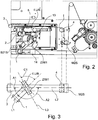
- the device provided at the beginning of the first paper run I for deflecting the paper strip also called a twist device, is shown in more detail.
- the paper strip is fed in an angular alignment to the transport plane of the paper strip during the subsequent transport movement.
- the transport plane of the paper strip in the manufacturing machine is the plane which is spanned by the various transport directions in which the paper strips are guided before entering the format section of the manufacturing machine.
- the transport plane can comprise a very short section which directly adjoins the twisting device or extends as far as the manufacturing machine. Due to the structure of the Apparatus, the transport plane usually runs parallel to a housing wall on which the deflectors, the pull roller pairs, the pull-cutting roller combinations and the sensors are mounted or fastened.
- the paper strip After the paper strip has entered the device, it is first guided past the first pair of draw rollers Z / W1, which generate a tensile force acting on the paper strip, through which the paper strip is transported. After leaving the pair of draw rollers Z / W1, the paper strip is guided over two deflections 1 and 2, between which the sensor B21S, which is directed at the paper strip, is arranged. The paper strip is then guided over a fixed deflection bolt fU / B, which is aligned with its longitudinal axis L3 in the direction of or parallel to the bisector between the longitudinal axes L1 and L2 of the paper strip in the feed and after leaving the deflection bolt fU / B runs.
- the alignment of the paper strip after leaving the deflection bolt f.U / B in the direction of the longitudinal axis L2 corresponds to the transport plane in which the paper strip is then transported through multiple deflections in different transport directions to the format tape 9.
- the single-width paper strip is divided into two single-width paper strips, which after leaving the Z / S / W1 pull-cutting roller combination are laterally offset into two planes offset parallel to the transport plane, so that the original transport plane is between the single-width paper strips runs.
- the guidance of the double-width paper strip can be seen from above.
- the paper strip is fed at a first angle A1 to the transport plane running through the longitudinal axis L2 of the paper strip after the deflection and is deflected and driven on the pair of pulling rollers Z / W1.
- the paper strip is deflected twice at the deflections 1 and 2 and guided towards the fixed deflection device fU / B, the deflection device 2 not being visible in this illustration.
- the fixed deflection bolt fU / B is aligned such that its longitudinal axis L3 in the direction of the bisector of the angle A2 or parallel to this runs.
- the fixed deflection bolt fU / B is arranged in such a way that the center line of the paper strip from the feed direction intersects the deflection bolt fU / B exactly in the middle, so that the paper strip is deflected without creating tension in the side edges of the paper strip.
- the angle A2 results from the difference of 180 degrees and the first angle A1.
- the paper strip After the paper strip has been deflected on the fixed deflection bolt f.U / B, the paper strip is again guided via two deflections 3 and 4 to the tensioning roller M2S, on which the tensile force in the paper strip for the proposed control of the pair of pulling rollers Z / W1 is measured.
- the fixed deflection bolt f.U / B is provided with an adjusting device 13, by means of which the angle A2 or C1 can be slightly adjusted for fine adjustment.
- the fixed deflection bolt f.U / B is to be regarded as fixed after the fine adjustment, i.e. the once set angle A1 is then constant.
- the adjusting device 13 is provided with a lockable locking device, not shown in detail.
- the paper strip After the paper strip has been deflected into the transport level, the paper strip is guided over the pivotably mounted tensioning roller M2S, which is used to tension the paper strip.
- the tensile force acting in the paper strip is sensed by means of the tensioning roller M2S and compared with a predetermined tensile force in a control device.
- a control signal is sent to the first pair of draw rollers Z / W1 to reduce or increase the tensile force, so that the control difference in the tensile force is compensated.
- the deflection bolt f.U / B is to be regarded as stationary during the transport movement of the paper strip, but it can be pivoted once for fine adjustment and to achieve different feed directions of the paper strip in a small angular range by means of an adjusting device 13. Furthermore, the entire device with the first pair of draw rollers Z / W1 and the fixed deflection bolt fU / B is arranged on a common frame 14, which, if necessary, can be mounted in different orientations to implement feed directions at a considerably different angle, so that feed directions of the paper strip in can be realized at any angle.
- a suction device 5 is arranged below the paper strip on the drain side of the paper strip, by means of which the paper particles loosening on the fixed deflection bolt f.U / B are sucked off.
- a twist device can also be provided on the second paper run II if the paper strip must or should be fed at an angle here as well.
Landscapes
- Controlling Rewinding, Feeding, Winding, Or Abnormalities Of Webs (AREA)
- Registering, Tensioning, Guiding Webs, And Rollers Therefor (AREA)
- Replacement Of Web Rolls (AREA)
- Making Paper Articles (AREA)
- Manufacturing Of Cigar And Cigarette Tobacco (AREA)
Claims (4)
- Dispositif de transport de matériau en forme de bande ou de ruban pour une machine destinée à la fabrication de produits en forme de tige de l'industrie de traitement du tabac, qui est guidé en deux couches superposées sur un moyen de renvoi (7, 18) et posé sur une bande de mise en format continuant à transporter les couches, les couches étant respectivement acheminées dans différents passages de papier (I,II), caractérisé en ce qu'un rouleau de tension est prévu dans le passage de papier (II) de la couche n'arrivant pas directement en appui contre la bande de mise en format (9), qui peut être commandé indirectement ou directement en fonction d'un moyen de mesure de force (12) disposé entre le rouleau de tension et le moyen de renvoi (7, 17).
- Dispositif selon la revendication 1, caractérisé en ce qu'un moyen (19) est prévu, au moyen duquel une pression supplémentaire peut être appliquée au niveau du moyen de renvoi (7, 18) à la couche n'arrivant pas en appui contre la bande de mise en format.
- Dispositif selon la revendication 2, caractérisé en ce que le moyen (19) est un moyen à air comprimé.
- Dispositif selon l'une quelconque des revendications précédentes, caractérisé en ce que le dispositif est conçu de telle manière que le matériau en forme de bande ou de ruban peut être acheminé à partir de différents premiers angles (A1) par rapport à un plan de transport du matériau en forme de bande ou de ruban dans le dispositif et, côté entrée du matériau en forme de bande ou de ruban, un moyen pour déplacer par coulissement le matériau en forme de bande ou de ruban transversalement à son axe longitudinal (L1) est prévu, qui peut être commandé en fonction d'un capteur de position (B19S) disposé dans la direction du parcours du matériau en forme de bande ou de ruban après un moyen d'écartement (15).
Priority Applications (1)
| Application Number | Priority Date | Filing Date | Title |
|---|---|---|---|
| PL13196195T PL2716170T5 (pl) | 2011-09-28 | 2012-09-14 | Urządzenie do transportu materiału taśmowego lub paskowego |
Applications Claiming Priority (2)
| Application Number | Priority Date | Filing Date | Title |
|---|---|---|---|
| DE102011114434A DE102011114434A1 (de) | 2011-09-28 | 2011-09-28 | Vorrichtung zum Transport von band- oder streifenförmigem Material |
| EP12184383.3A EP2574244B1 (fr) | 2011-09-28 | 2012-09-14 | Dispositif de transport de matériau en forme de bande ou de ruban |
Related Parent Applications (2)
| Application Number | Title | Priority Date | Filing Date |
|---|---|---|---|
| EP12184383.3A Division EP2574244B1 (fr) | 2011-09-28 | 2012-09-14 | Dispositif de transport de matériau en forme de bande ou de ruban |
| EP12184383.3A Division-Into EP2574244B1 (fr) | 2011-09-28 | 2012-09-14 | Dispositif de transport de matériau en forme de bande ou de ruban |
Publications (3)
| Publication Number | Publication Date |
|---|---|
| EP2716170A1 EP2716170A1 (fr) | 2014-04-09 |
| EP2716170B1 EP2716170B1 (fr) | 2016-02-03 |
| EP2716170B2 true EP2716170B2 (fr) | 2021-09-22 |
Family
ID=46963479
Family Applications (3)
| Application Number | Title | Priority Date | Filing Date |
|---|---|---|---|
| EP13196193.0A Revoked EP2712508B1 (fr) | 2011-09-28 | 2012-09-14 | Dispositif de transport de matériau en forme de bande ou de ruban |
| EP13196195.5A Active EP2716170B2 (fr) | 2011-09-28 | 2012-09-14 | Dispositif de transport de matériau en forme de bande ou de ruban |
| EP12184383.3A Revoked EP2574244B1 (fr) | 2011-09-28 | 2012-09-14 | Dispositif de transport de matériau en forme de bande ou de ruban |
Family Applications Before (1)
| Application Number | Title | Priority Date | Filing Date |
|---|---|---|---|
| EP13196193.0A Revoked EP2712508B1 (fr) | 2011-09-28 | 2012-09-14 | Dispositif de transport de matériau en forme de bande ou de ruban |
Family Applications After (1)
| Application Number | Title | Priority Date | Filing Date |
|---|---|---|---|
| EP12184383.3A Revoked EP2574244B1 (fr) | 2011-09-28 | 2012-09-14 | Dispositif de transport de matériau en forme de bande ou de ruban |
Country Status (4)
| Country | Link |
|---|---|
| EP (3) | EP2712508B1 (fr) |
| CN (1) | CN103030022B (fr) |
| DE (1) | DE102011114434A1 (fr) |
| PL (3) | PL2716170T5 (fr) |
Families Citing this family (3)
| Publication number | Priority date | Publication date | Assignee | Title |
|---|---|---|---|---|
| WO2016049899A1 (fr) * | 2014-09-30 | 2016-04-07 | 惠州市吉瑞科技有限公司 | Dispositif de distribution de matériau |
| DE102018110762B4 (de) * | 2018-05-04 | 2019-11-21 | Hauni Maschinenbau Gmbh | Herstellung von Strängen der Tabak verarbeitenden Industrie, insbesondere von Hohlsträngen |
| CN113619296B (zh) * | 2021-07-23 | 2023-01-13 | 天津七所精密机电技术有限公司 | 适用于绘图仪的高精度步进走纸运动系统及走纸控制方法 |
Family Cites Families (20)
| Publication number | Priority date | Publication date | Assignee | Title |
|---|---|---|---|---|
| GB279608A (en) | 1926-09-29 | 1927-11-03 | Ernest Arthur Timson | Improvements in or relating to web-guiding devices for printing and other machines |
| GB468444A (en) | 1936-01-03 | 1937-07-05 | Charles Edward Taroni | Improvements in and relating to the manufacture of sponge cake and the like web material |
| GB582530A (en) | 1944-04-04 | 1946-11-20 | Dunlop Rubber Co | Improvements in or relating to conveyors for web material |
| GB879535A (en) | 1957-07-16 | 1961-10-11 | W H Smith & Son Alacra Ltd | Improvements in or relating to addressing machines |
| DE1186247B (de) | 1960-05-25 | 1965-01-28 | Philips Nv | Vorrichtung zum Auf- und Abwickeln eines bandfoermigen Aufzeichnungstraegers auf bzw. von einer drehbaren Flanschspule |
| GB957740A (en) | 1961-08-04 | 1964-05-13 | Horace Alexander Stone | A device for guiding continuously moving webs |
| GB1230257A (fr) | 1968-07-19 | 1971-04-28 | ||
| GB1281478A (en) | 1969-10-17 | 1972-07-12 | Windmoeller & Hoelscher | Turning device for deflecting moving webs |
| IT1133242B (it) | 1980-02-27 | 1986-07-09 | Gd Spa | Dispositivo deviatore per nastri,particolarmente nastri di carta |
| DE3401323A1 (de) * | 1983-02-01 | 1984-08-02 | Hauni-Werke Körber & Co KG, 2050 Hamburg | Verfahren und vorrichtung zum gleichzeitigen herstellen mehrerer umhuellter faserstraenge der tabakverarbeitenden industrie |
| USRE36154E (en) | 1984-02-23 | 1999-03-23 | G.D. Societa Per Azioni | Device for supplying webs of wrapping material to a cigarette making machine of the two rod type |
| IT1186553B (it) | 1985-01-16 | 1987-12-04 | Gd Spa | Dispositivo di alimentazione di carta in nastro in una macchina confezionatrice di sigarette |
| IT1189914B (it) | 1986-01-20 | 1988-02-10 | Gd Spa | Dispositivo di alimentazione di carta in nastro in una macchina confezionatrice di sigarette a doppio baco |
| GB2189467A (en) | 1986-04-23 | 1987-10-28 | New Jersey Machine Inc | Label dispenser with articulated guide |
| DE3809125A1 (de) | 1988-03-18 | 1989-09-28 | Sengewald Kg Karl H | Verfahren und vorrichtung zum rapportmaessigen verbinden von in beutelabschnitte unterteilten folienschlaeuchen |
| US5156169A (en) | 1990-11-06 | 1992-10-20 | R. J. Reynolds Tobacco Company | Apparatus for making cigarettes |
| GB9422998D0 (en) | 1994-11-15 | 1995-01-04 | Rothmans International Ltd | Method and apparatus for wrapping a rod of smoking material |
| IT1287614B1 (it) * | 1996-12-24 | 1998-08-06 | Gd Spa | Metodo per l'alimentazione di materiale di incarto in macchine confezionatrici |
| DE10044577A1 (de) | 2000-09-08 | 2002-03-21 | Hauni Maschinenbau Ag | Verfahren und Vorrichtung zum Trennen einer doppeltbreiten Ausgangs-Hüllmaterialbahn in zwei Teilbahnen |
| JP3949139B2 (ja) * | 2002-11-19 | 2007-07-25 | ブラウン アンド ウィリアムソン ホールディングス | 燃焼速度が調整された紙巻きタバコを製造するための装置 |
-
2011
- 2011-09-28 DE DE102011114434A patent/DE102011114434A1/de active Pending
-
2012
- 2012-09-14 PL PL13196195T patent/PL2716170T5/pl unknown
- 2012-09-14 EP EP13196193.0A patent/EP2712508B1/fr not_active Revoked
- 2012-09-14 EP EP13196195.5A patent/EP2716170B2/fr active Active
- 2012-09-14 EP EP12184383.3A patent/EP2574244B1/fr not_active Revoked
- 2012-09-14 PL PL12184383T patent/PL2574244T3/pl unknown
- 2012-09-14 PL PL13196193T patent/PL2712508T3/pl unknown
- 2012-09-27 CN CN201210368912.5A patent/CN103030022B/zh active Active
Also Published As
| Publication number | Publication date |
|---|---|
| EP2574244A2 (fr) | 2013-04-03 |
| DE102011114434A1 (de) | 2013-03-28 |
| EP2716170B1 (fr) | 2016-02-03 |
| PL2712508T3 (pl) | 2016-07-29 |
| PL2716170T5 (pl) | 2021-12-27 |
| EP2574244A3 (fr) | 2013-06-19 |
| CN103030022B (zh) | 2017-04-26 |
| EP2712508A1 (fr) | 2014-04-02 |
| EP2716170A1 (fr) | 2014-04-09 |
| PL2574244T3 (pl) | 2016-08-31 |
| PL2716170T3 (pl) | 2016-07-29 |
| CN103030022A (zh) | 2013-04-10 |
| EP2574244B1 (fr) | 2016-02-03 |
| EP2712508B1 (fr) | 2016-02-03 |
Similar Documents
| Publication | Publication Date | Title |
|---|---|---|
| DE19641509C2 (de) | Verfahren zum Transport eines Gürtelaufbaustreifens zum Aufbau eines Gürtels für einen Fahrzeugluftreifen | |
| DE4436667A1 (de) | Packverfahren und -vorrichtung | |
| EP1314668B1 (fr) | Dispositif pour transporter materiau en bande | |
| EP3694799B1 (fr) | Dispositif d'orientation de feuille, machine pour le traitement d'une feuille ainsi que procédé pour l'orientation d'une feuille | |
| EP1790601A2 (fr) | Contrôle de la tension d'une bande de matériau | |
| EP2268481B1 (fr) | Dispositif et procede de fabrication de sachets | |
| EP3336228B1 (fr) | Procédé de fonctionnement d'un banc d'étirage ainsi que banc d'étirage destiné à l'étirage d'un ruban de fibre | |
| EP2716170B2 (fr) | Dispositif de transport de matériau en forme de bande ou de ruban | |
| EP2255681B1 (fr) | Machine de fabrication de lignes de l'industrie de traitement du tabac | |
| DE102014104662B4 (de) | Arbeitsverfahren für den digitalen Multipass-Mehrfarbendruck | |
| WO2019002259A2 (fr) | Procédé et dispositif pour orienter des découpes de boîtes pliantes | |
| DE19850901A1 (de) | Vorrichtung zum Transport von einander zu überlappenden Bögen, insbesondere Papierbögen | |
| EP3737630B1 (fr) | Arrangement pour découper une bande de matière en feuilles individuelles avec un accumulateur de bande | |
| EP3059195B1 (fr) | Dispositif de pliage et procédé | |
| EP4302985B1 (fr) | Dispositif et procédé de fabrication de tubes creux | |
| EP2074895A1 (fr) | Dispositif de garniture d'une machine de l'industrie de traitement du tabac | |
| EP3142952B1 (fr) | Dispositif et procédé pour régler la position d'une bande de matériau d'emballage rélatif à une référence dans une machine d'emballage | |
| DE3744107C2 (fr) | ||
| EP1522513A2 (fr) | Dispositif pour séparer des produits plats disposés en formation imbriquée | |
| EP1661833A1 (fr) | Procédé et dispositif pour traiter des produits imprimés | |
| DE202013104653U1 (de) | Slitter zum Schneiden eines Cordbandes | |
| DE102012207286B4 (de) | Verfahren zum einstellen zumindest einer einrichtung einer kuvertiervorrichtung und kuvertiervorrichtung | |
| DE102024100128A1 (de) | Umlenkwalze für bahnförmiges Flachmaterial und Verfahren zum Umlenken von bahnförmigem Flachmaterial | |
| WO2024002720A1 (fr) | Machine dans l'industrie de transformation du tabac pour la production d'une tige, et procédé de production d'une tige dans l'industrie de transformation du tabac | |
| DE102017005786A1 (de) | Transportvorrichtung für einen Umhüllungsstreifen für Produkte der Tabak verarbeitenden Industrie und Verfahren zur Steuerung einer derartigen Transportvorrichtung |
Legal Events
| Date | Code | Title | Description |
|---|---|---|---|
| PUAI | Public reference made under article 153(3) epc to a published international application that has entered the european phase |
Free format text: ORIGINAL CODE: 0009012 |
|
| AC | Divisional application: reference to earlier application |
Ref document number: 2574244 Country of ref document: EP Kind code of ref document: P |
|
| AK | Designated contracting states |
Kind code of ref document: A1 Designated state(s): AL AT BE BG CH CY CZ DE DK EE ES FI FR GB GR HR HU IE IS IT LI LT LU LV MC MK MT NL NO PL PT RO RS SE SI SK SM TR |
|
| AX | Request for extension of the european patent |
Extension state: BA ME |
|
| TPAC | Observations filed by third parties |
Free format text: ORIGINAL CODE: EPIDOSNTIPA |
|
| 17P | Request for examination filed |
Effective date: 20140919 |
|
| RBV | Designated contracting states (corrected) |
Designated state(s): AL AT BE BG CH CY CZ DE DK EE ES FI FR GB GR HR HU IE IS IT LI LT LU LV MC MK MT NL NO PL PT RO RS SE SI SK SM TR |
|
| GRAP | Despatch of communication of intention to grant a patent |
Free format text: ORIGINAL CODE: EPIDOSNIGR1 |
|
| RIC1 | Information provided on ipc code assigned before grant |
Ipc: A24C 5/20 20060101AFI20150420BHEP |
|
| INTG | Intention to grant announced |
Effective date: 20150508 |
|
| GRAS | Grant fee paid |
Free format text: ORIGINAL CODE: EPIDOSNIGR3 |
|
| GRAA | (expected) grant |
Free format text: ORIGINAL CODE: 0009210 |
|
| AC | Divisional application: reference to earlier application |
Ref document number: 2574244 Country of ref document: EP Kind code of ref document: P |
|
| AK | Designated contracting states |
Kind code of ref document: B1 Designated state(s): AL AT BE BG CH CY CZ DE DK EE ES FI FR GB GR HR HU IE IS IT LI LT LU LV MC MK MT NL NO PL PT RO RS SE SI SK SM TR |
|
| REG | Reference to a national code |
Ref country code: GB Ref legal event code: FG4D Free format text: NOT ENGLISH |
|
| REG | Reference to a national code |
Ref country code: AT Ref legal event code: REF Ref document number: 773232 Country of ref document: AT Kind code of ref document: T Effective date: 20160215 Ref country code: CH Ref legal event code: EP |
|
| REG | Reference to a national code |
Ref country code: IE Ref legal event code: FG4D Free format text: LANGUAGE OF EP DOCUMENT: GERMAN |
|
| REG | Reference to a national code |
Ref country code: DE Ref legal event code: R096 Ref document number: 502012005949 Country of ref document: DE |
|
| REG | Reference to a national code |
Ref country code: NL Ref legal event code: FP |
|
| REG | Reference to a national code |
Ref country code: LT Ref legal event code: MG4D |
|
| RAP2 | Party data changed (patent owner data changed or rights of a patent transferred) |
Owner name: HAUNI MASCHINENBAU GMBH |
|
| REG | Reference to a national code |
Ref country code: DE Ref legal event code: R081 Ref document number: 502012005949 Country of ref document: DE Owner name: HAUNI MASCHINENBAU GMBH, DE Free format text: FORMER OWNER: HAUNI MASCHINENBAU AG, 21033 HAMBURG, DE |
|
| PG25 | Lapsed in a contracting state [announced via postgrant information from national office to epo] |
Ref country code: NO Free format text: LAPSE BECAUSE OF FAILURE TO SUBMIT A TRANSLATION OF THE DESCRIPTION OR TO PAY THE FEE WITHIN THE PRESCRIBED TIME-LIMIT Effective date: 20160503 Ref country code: FI Free format text: LAPSE BECAUSE OF FAILURE TO SUBMIT A TRANSLATION OF THE DESCRIPTION OR TO PAY THE FEE WITHIN THE PRESCRIBED TIME-LIMIT Effective date: 20160203 Ref country code: ES Free format text: LAPSE BECAUSE OF FAILURE TO SUBMIT A TRANSLATION OF THE DESCRIPTION OR TO PAY THE FEE WITHIN THE PRESCRIBED TIME-LIMIT Effective date: 20160203 Ref country code: HR Free format text: LAPSE BECAUSE OF FAILURE TO SUBMIT A TRANSLATION OF THE DESCRIPTION OR TO PAY THE FEE WITHIN THE PRESCRIBED TIME-LIMIT Effective date: 20160203 Ref country code: GR Free format text: LAPSE BECAUSE OF FAILURE TO SUBMIT A TRANSLATION OF THE DESCRIPTION OR TO PAY THE FEE WITHIN THE PRESCRIBED TIME-LIMIT Effective date: 20160504 |
|
| PG25 | Lapsed in a contracting state [announced via postgrant information from national office to epo] |
Ref country code: PT Free format text: LAPSE BECAUSE OF FAILURE TO SUBMIT A TRANSLATION OF THE DESCRIPTION OR TO PAY THE FEE WITHIN THE PRESCRIBED TIME-LIMIT Effective date: 20160603 Ref country code: SE Free format text: LAPSE BECAUSE OF FAILURE TO SUBMIT A TRANSLATION OF THE DESCRIPTION OR TO PAY THE FEE WITHIN THE PRESCRIBED TIME-LIMIT Effective date: 20160203 Ref country code: LT Free format text: LAPSE BECAUSE OF FAILURE TO SUBMIT A TRANSLATION OF THE DESCRIPTION OR TO PAY THE FEE WITHIN THE PRESCRIBED TIME-LIMIT Effective date: 20160203 Ref country code: LV Free format text: LAPSE BECAUSE OF FAILURE TO SUBMIT A TRANSLATION OF THE DESCRIPTION OR TO PAY THE FEE WITHIN THE PRESCRIBED TIME-LIMIT Effective date: 20160203 Ref country code: RS Free format text: LAPSE BECAUSE OF FAILURE TO SUBMIT A TRANSLATION OF THE DESCRIPTION OR TO PAY THE FEE WITHIN THE PRESCRIBED TIME-LIMIT Effective date: 20160203 Ref country code: IS Free format text: LAPSE BECAUSE OF FAILURE TO SUBMIT A TRANSLATION OF THE DESCRIPTION OR TO PAY THE FEE WITHIN THE PRESCRIBED TIME-LIMIT Effective date: 20160603 |
|
| REG | Reference to a national code |
Ref country code: NL Ref legal event code: PD Owner name: HAUNI MASCHINENBAU GMBH; DE Free format text: DETAILS ASSIGNMENT: VERANDERING VAN EIGENAAR(S), VERANDERING VAN DE JURIDISCHE ENTITEIT; FORMER OWNER NAME: HAUNI MASCHINENBAU AG Effective date: 20160704 |
|
| PG25 | Lapsed in a contracting state [announced via postgrant information from national office to epo] |
Ref country code: EE Free format text: LAPSE BECAUSE OF FAILURE TO SUBMIT A TRANSLATION OF THE DESCRIPTION OR TO PAY THE FEE WITHIN THE PRESCRIBED TIME-LIMIT Effective date: 20160203 Ref country code: DK Free format text: LAPSE BECAUSE OF FAILURE TO SUBMIT A TRANSLATION OF THE DESCRIPTION OR TO PAY THE FEE WITHIN THE PRESCRIBED TIME-LIMIT Effective date: 20160203 |
|
| REG | Reference to a national code |
Ref country code: DE Ref legal event code: R026 Ref document number: 502012005949 Country of ref document: DE |
|
| PLBI | Opposition filed |
Free format text: ORIGINAL CODE: 0009260 |
|
| PG25 | Lapsed in a contracting state [announced via postgrant information from national office to epo] |
Ref country code: CZ Free format text: LAPSE BECAUSE OF FAILURE TO SUBMIT A TRANSLATION OF THE DESCRIPTION OR TO PAY THE FEE WITHIN THE PRESCRIBED TIME-LIMIT Effective date: 20160203 Ref country code: SM Free format text: LAPSE BECAUSE OF FAILURE TO SUBMIT A TRANSLATION OF THE DESCRIPTION OR TO PAY THE FEE WITHIN THE PRESCRIBED TIME-LIMIT Effective date: 20160203 Ref country code: SK Free format text: LAPSE BECAUSE OF FAILURE TO SUBMIT A TRANSLATION OF THE DESCRIPTION OR TO PAY THE FEE WITHIN THE PRESCRIBED TIME-LIMIT Effective date: 20160203 Ref country code: RO Free format text: LAPSE BECAUSE OF FAILURE TO SUBMIT A TRANSLATION OF THE DESCRIPTION OR TO PAY THE FEE WITHIN THE PRESCRIBED TIME-LIMIT Effective date: 20160203 |
|
| 26 | Opposition filed |
Opponent name: G.D S.P.A. Effective date: 20161103 |
|
| PLAX | Notice of opposition and request to file observation + time limit sent |
Free format text: ORIGINAL CODE: EPIDOSNOBS2 |
|
| PG25 | Lapsed in a contracting state [announced via postgrant information from national office to epo] |
Ref country code: SI Free format text: LAPSE BECAUSE OF FAILURE TO SUBMIT A TRANSLATION OF THE DESCRIPTION OR TO PAY THE FEE WITHIN THE PRESCRIBED TIME-LIMIT Effective date: 20160203 Ref country code: BG Free format text: LAPSE BECAUSE OF FAILURE TO SUBMIT A TRANSLATION OF THE DESCRIPTION OR TO PAY THE FEE WITHIN THE PRESCRIBED TIME-LIMIT Effective date: 20160503 Ref country code: BE Free format text: LAPSE BECAUSE OF NON-PAYMENT OF DUE FEES Effective date: 20160930 |
|
| PLBB | Reply of patent proprietor to notice(s) of opposition received |
Free format text: ORIGINAL CODE: EPIDOSNOBS3 |
|
| PG25 | Lapsed in a contracting state [announced via postgrant information from national office to epo] |
Ref country code: MC Free format text: LAPSE BECAUSE OF FAILURE TO SUBMIT A TRANSLATION OF THE DESCRIPTION OR TO PAY THE FEE WITHIN THE PRESCRIBED TIME-LIMIT Effective date: 20160203 |
|
| REG | Reference to a national code |
Ref country code: CH Ref legal event code: PL |
|
| GBPC | Gb: european patent ceased through non-payment of renewal fee |
Effective date: 20160914 |
|
| REG | Reference to a national code |
Ref country code: IE Ref legal event code: MM4A |
|
| REG | Reference to a national code |
Ref country code: FR Ref legal event code: ST Effective date: 20170531 |
|
| PG25 | Lapsed in a contracting state [announced via postgrant information from national office to epo] |
Ref country code: FR Free format text: LAPSE BECAUSE OF NON-PAYMENT OF DUE FEES Effective date: 20160930 Ref country code: IE Free format text: LAPSE BECAUSE OF NON-PAYMENT OF DUE FEES Effective date: 20160914 Ref country code: GB Free format text: LAPSE BECAUSE OF NON-PAYMENT OF DUE FEES Effective date: 20160914 Ref country code: CH Free format text: LAPSE BECAUSE OF NON-PAYMENT OF DUE FEES Effective date: 20160930 Ref country code: LI Free format text: LAPSE BECAUSE OF NON-PAYMENT OF DUE FEES Effective date: 20160930 |
|
| PG25 | Lapsed in a contracting state [announced via postgrant information from national office to epo] |
Ref country code: LU Free format text: LAPSE BECAUSE OF NON-PAYMENT OF DUE FEES Effective date: 20160914 |
|
| REG | Reference to a national code |
Ref country code: BE Ref legal event code: MM Effective date: 20160930 |
|
| PG25 | Lapsed in a contracting state [announced via postgrant information from national office to epo] |
Ref country code: CY Free format text: LAPSE BECAUSE OF FAILURE TO SUBMIT A TRANSLATION OF THE DESCRIPTION OR TO PAY THE FEE WITHIN THE PRESCRIBED TIME-LIMIT Effective date: 20160203 Ref country code: HU Free format text: LAPSE BECAUSE OF FAILURE TO SUBMIT A TRANSLATION OF THE DESCRIPTION OR TO PAY THE FEE WITHIN THE PRESCRIBED TIME-LIMIT; INVALID AB INITIO Effective date: 20120914 |
|
| PG25 | Lapsed in a contracting state [announced via postgrant information from national office to epo] |
Ref country code: MT Free format text: LAPSE BECAUSE OF FAILURE TO SUBMIT A TRANSLATION OF THE DESCRIPTION OR TO PAY THE FEE WITHIN THE PRESCRIBED TIME-LIMIT Effective date: 20160203 Ref country code: MK Free format text: LAPSE BECAUSE OF FAILURE TO SUBMIT A TRANSLATION OF THE DESCRIPTION OR TO PAY THE FEE WITHIN THE PRESCRIBED TIME-LIMIT Effective date: 20160203 |
|
| APBM | Appeal reference recorded |
Free format text: ORIGINAL CODE: EPIDOSNREFNO |
|
| APBP | Date of receipt of notice of appeal recorded |
Free format text: ORIGINAL CODE: EPIDOSNNOA2O |
|
| APAH | Appeal reference modified |
Free format text: ORIGINAL CODE: EPIDOSCREFNO |
|
| APBQ | Date of receipt of statement of grounds of appeal recorded |
Free format text: ORIGINAL CODE: EPIDOSNNOA3O |
|
| PG25 | Lapsed in a contracting state [announced via postgrant information from national office to epo] |
Ref country code: AL Free format text: LAPSE BECAUSE OF FAILURE TO SUBMIT A TRANSLATION OF THE DESCRIPTION OR TO PAY THE FEE WITHIN THE PRESCRIBED TIME-LIMIT Effective date: 20160203 Ref country code: TR Free format text: LAPSE BECAUSE OF FAILURE TO SUBMIT A TRANSLATION OF THE DESCRIPTION OR TO PAY THE FEE WITHIN THE PRESCRIBED TIME-LIMIT Effective date: 20160203 |
|
| REG | Reference to a national code |
Ref country code: AT Ref legal event code: MM01 Ref document number: 773232 Country of ref document: AT Kind code of ref document: T Effective date: 20170914 |
|
| PG25 | Lapsed in a contracting state [announced via postgrant information from national office to epo] |
Ref country code: AT Free format text: LAPSE BECAUSE OF NON-PAYMENT OF DUE FEES Effective date: 20170914 |
|
| APAH | Appeal reference modified |
Free format text: ORIGINAL CODE: EPIDOSCREFNO |
|
| APBU | Appeal procedure closed |
Free format text: ORIGINAL CODE: EPIDOSNNOA9O |
|
| PUAH | Patent maintained in amended form |
Free format text: ORIGINAL CODE: 0009272 |
|
| STAA | Information on the status of an ep patent application or granted ep patent |
Free format text: STATUS: PATENT MAINTAINED AS AMENDED |
|
| 27A | Patent maintained in amended form |
Effective date: 20210922 |
|
| AK | Designated contracting states |
Kind code of ref document: B2 Designated state(s): AL AT BE BG CH CY CZ DE DK EE ES FI FR GB GR HR HU IE IS IT LI LT LU LV MC MK MT NL NO PL PT RO RS SE SI SK SM TR |
|
| REG | Reference to a national code |
Ref country code: DE Ref legal event code: R102 Ref document number: 502012005949 Country of ref document: DE |
|
| REG | Reference to a national code |
Ref country code: NL Ref legal event code: FP |
|
| REG | Reference to a national code |
Ref country code: DE Ref legal event code: R081 Ref document number: 502012005949 Country of ref document: DE Owner name: KOERBER TECHNOLOGIES GMBH, DE Free format text: FORMER OWNER: HAUNI MASCHINENBAU GMBH, 21033 HAMBURG, DE |
|
| REG | Reference to a national code |
Ref country code: NL Ref legal event code: HC Owner name: KOERBER TECHNOLOGIES GMBH; DE Free format text: DETAILS ASSIGNMENT: CHANGE OF OWNER(S), CHANGE OF OWNER(S) NAME; FORMER OWNER NAME: HAUNI MASCHINENBAU GMBH Effective date: 20221031 |
|
| P01 | Opt-out of the competence of the unified patent court (upc) registered |
Effective date: 20230621 |
|
| PGFP | Annual fee paid to national office [announced via postgrant information from national office to epo] |
Ref country code: PL Payment date: 20250825 Year of fee payment: 14 Ref country code: IT Payment date: 20250929 Year of fee payment: 14 Ref country code: NL Payment date: 20250927 Year of fee payment: 14 |
|
| PGFP | Annual fee paid to national office [announced via postgrant information from national office to epo] |
Ref country code: DE Payment date: 20251002 Year of fee payment: 14 |