EP2716396A1 - Hohle gekrümmte platte, herstellungsverfahren dafür und brenner für eine gasturbine - Google Patents
Hohle gekrümmte platte, herstellungsverfahren dafür und brenner für eine gasturbine Download PDFInfo
- Publication number
- EP2716396A1 EP2716396A1 EP12789220.6A EP12789220A EP2716396A1 EP 2716396 A1 EP2716396 A1 EP 2716396A1 EP 12789220 A EP12789220 A EP 12789220A EP 2716396 A1 EP2716396 A1 EP 2716396A1
- Authority
- EP
- European Patent Office
- Prior art keywords
- plate member
- groove
- plate
- hollow
- hollow curved
- Prior art date
- Legal status (The legal status is an assumption and is not a legal conclusion. Google has not performed a legal analysis and makes no representation as to the accuracy of the status listed.)
- Granted
Links
Images


Classifications
-
- B—PERFORMING OPERATIONS; TRANSPORTING
- B23—MACHINE TOOLS; METAL-WORKING NOT OTHERWISE PROVIDED FOR
- B23K—SOLDERING OR UNSOLDERING; WELDING; CLADDING OR PLATING BY SOLDERING OR WELDING; CUTTING BY APPLYING HEAT LOCALLY, e.g. FLAME CUTTING; WORKING BY LASER BEAM
- B23K20/00—Non-electric welding by applying impact or other pressure, with or without the application of heat, e.g. cladding or plating
-
- F—MECHANICAL ENGINEERING; LIGHTING; HEATING; WEAPONS; BLASTING
- F01—MACHINES OR ENGINES IN GENERAL; ENGINE PLANTS IN GENERAL; STEAM ENGINES
- F01D—NON-POSITIVE DISPLACEMENT MACHINES OR ENGINES, e.g. STEAM TURBINES
- F01D11/00—Preventing or minimising internal leakage of working-fluid, e.g. between stages
- F01D11/08—Preventing or minimising internal leakage of working-fluid, e.g. between stages for sealing space between rotor blade tips and stator
-
- F—MECHANICAL ENGINEERING; LIGHTING; HEATING; WEAPONS; BLASTING
- F02—COMBUSTION ENGINES; HOT-GAS OR COMBUSTION-PRODUCT ENGINE PLANTS
- F02C—GAS-TURBINE PLANTS; AIR INTAKES FOR JET-PROPULSION PLANTS; CONTROLLING FUEL SUPPLY IN AIR-BREATHING JET-PROPULSION PLANTS
- F02C7/00—Features, components parts, details or accessories, not provided for in, or of interest apart form groups F02C1/00 - F02C6/00; Air intakes for jet-propulsion plants
-
- B—PERFORMING OPERATIONS; TRANSPORTING
- B21—MECHANICAL METAL-WORKING WITHOUT ESSENTIALLY REMOVING MATERIAL; PUNCHING METAL
- B21D—WORKING OR PROCESSING OF SHEET METAL OR METAL TUBES, RODS OR PROFILES WITHOUT ESSENTIALLY REMOVING MATERIAL; PUNCHING METAL
- B21D5/00—Bending sheet metal along straight lines, e.g. to form simple curves
- B21D5/01—Bending sheet metal along straight lines, e.g. to form simple curves between rams and anvils or abutments
-
- B—PERFORMING OPERATIONS; TRANSPORTING
- B21—MECHANICAL METAL-WORKING WITHOUT ESSENTIALLY REMOVING MATERIAL; PUNCHING METAL
- B21D—WORKING OR PROCESSING OF SHEET METAL OR METAL TUBES, RODS OR PROFILES WITHOUT ESSENTIALLY REMOVING MATERIAL; PUNCHING METAL
- B21D5/00—Bending sheet metal along straight lines, e.g. to form simple curves
- B21D5/06—Bending sheet metal along straight lines, e.g. to form simple curves by drawing procedure making use of dies or forming-rollers, e.g. making profiles
-
- B—PERFORMING OPERATIONS; TRANSPORTING
- B21—MECHANICAL METAL-WORKING WITHOUT ESSENTIALLY REMOVING MATERIAL; PUNCHING METAL
- B21D—WORKING OR PROCESSING OF SHEET METAL OR METAL TUBES, RODS OR PROFILES WITHOUT ESSENTIALLY REMOVING MATERIAL; PUNCHING METAL
- B21D53/00—Making other particular articles
- B21D53/92—Making other particular articles other parts for aircraft
-
- B—PERFORMING OPERATIONS; TRANSPORTING
- B23—MACHINE TOOLS; METAL-WORKING NOT OTHERWISE PROVIDED FOR
- B23K—SOLDERING OR UNSOLDERING; WELDING; CLADDING OR PLATING BY SOLDERING OR WELDING; CUTTING BY APPLYING HEAT LOCALLY, e.g. FLAME CUTTING; WORKING BY LASER BEAM
- B23K20/00—Non-electric welding by applying impact or other pressure, with or without the application of heat, e.g. cladding or plating
- B23K20/02—Non-electric welding by applying impact or other pressure, with or without the application of heat, e.g. cladding or plating by means of a press ; Diffusion bonding
-
- F—MECHANICAL ENGINEERING; LIGHTING; HEATING; WEAPONS; BLASTING
- F02—COMBUSTION ENGINES; HOT-GAS OR COMBUSTION-PRODUCT ENGINE PLANTS
- F02C—GAS-TURBINE PLANTS; AIR INTAKES FOR JET-PROPULSION PLANTS; CONTROLLING FUEL SUPPLY IN AIR-BREATHING JET-PROPULSION PLANTS
- F02C7/00—Features, components parts, details or accessories, not provided for in, or of interest apart form groups F02C1/00 - F02C6/00; Air intakes for jet-propulsion plants
- F02C7/12—Cooling of plants
- F02C7/16—Cooling of plants characterised by cooling medium
- F02C7/18—Cooling of plants characterised by cooling medium the medium being gaseous, e.g. air
-
- F—MECHANICAL ENGINEERING; LIGHTING; HEATING; WEAPONS; BLASTING
- F23—COMBUSTION APPARATUS; COMBUSTION PROCESSES
- F23R—GENERATING COMBUSTION PRODUCTS OF HIGH PRESSURE OR HIGH VELOCITY, e.g. GAS-TURBINE COMBUSTION CHAMBERS
- F23R3/00—Continuous combustion chambers using liquid or gaseous fuel
- F23R3/002—Wall structures
-
- F—MECHANICAL ENGINEERING; LIGHTING; HEATING; WEAPONS; BLASTING
- F23—COMBUSTION APPARATUS; COMBUSTION PROCESSES
- F23R—GENERATING COMBUSTION PRODUCTS OF HIGH PRESSURE OR HIGH VELOCITY, e.g. GAS-TURBINE COMBUSTION CHAMBERS
- F23R3/00—Continuous combustion chambers using liquid or gaseous fuel
- F23R3/005—Combined with pressure or heat exchangers
-
- F—MECHANICAL ENGINEERING; LIGHTING; HEATING; WEAPONS; BLASTING
- F23—COMBUSTION APPARATUS; COMBUSTION PROCESSES
- F23R—GENERATING COMBUSTION PRODUCTS OF HIGH PRESSURE OR HIGH VELOCITY, e.g. GAS-TURBINE COMBUSTION CHAMBERS
- F23R3/00—Continuous combustion chambers using liquid or gaseous fuel
- F23R3/02—Continuous combustion chambers using liquid or gaseous fuel characterised by the air-flow or gas-flow configuration
- F23R3/04—Air inlet arrangements
- F23R3/06—Arrangement of apertures along the flame tube
-
- F—MECHANICAL ENGINEERING; LIGHTING; HEATING; WEAPONS; BLASTING
- F23—COMBUSTION APPARATUS; COMBUSTION PROCESSES
- F23R—GENERATING COMBUSTION PRODUCTS OF HIGH PRESSURE OR HIGH VELOCITY, e.g. GAS-TURBINE COMBUSTION CHAMBERS
- F23R3/00—Continuous combustion chambers using liquid or gaseous fuel
- F23R3/42—Continuous combustion chambers using liquid or gaseous fuel characterised by the arrangement or form of the flame tubes or combustion chambers
-
- B—PERFORMING OPERATIONS; TRANSPORTING
- B23—MACHINE TOOLS; METAL-WORKING NOT OTHERWISE PROVIDED FOR
- B23K—SOLDERING OR UNSOLDERING; WELDING; CLADDING OR PLATING BY SOLDERING OR WELDING; CUTTING BY APPLYING HEAT LOCALLY, e.g. FLAME CUTTING; WORKING BY LASER BEAM
- B23K2101/00—Articles made by soldering, welding or cutting
- B23K2101/001—Turbines
-
- F—MECHANICAL ENGINEERING; LIGHTING; HEATING; WEAPONS; BLASTING
- F05—INDEXING SCHEMES RELATING TO ENGINES OR PUMPS IN VARIOUS SUBCLASSES OF CLASSES F01-F04
- F05D—INDEXING SCHEME FOR ASPECTS RELATING TO NON-POSITIVE-DISPLACEMENT MACHINES OR ENGINES, GAS-TURBINES OR JET-PROPULSION PLANTS
- F05D2230/00—Manufacture
- F05D2230/20—Manufacture essentially without removing material
- F05D2230/23—Manufacture essentially without removing material by permanently joining parts together
- F05D2230/232—Manufacture essentially without removing material by permanently joining parts together by welding
- F05D2230/236—Diffusion bonding
-
- F—MECHANICAL ENGINEERING; LIGHTING; HEATING; WEAPONS; BLASTING
- F05—INDEXING SCHEMES RELATING TO ENGINES OR PUMPS IN VARIOUS SUBCLASSES OF CLASSES F01-F04
- F05D—INDEXING SCHEME FOR ASPECTS RELATING TO NON-POSITIVE-DISPLACEMENT MACHINES OR ENGINES, GAS-TURBINES OR JET-PROPULSION PLANTS
- F05D2250/00—Geometry
- F05D2250/20—Three-dimensional
- F05D2250/29—Three-dimensional machined; miscellaneous
- F05D2250/291—Three-dimensional machined; miscellaneous hollowed
-
- F—MECHANICAL ENGINEERING; LIGHTING; HEATING; WEAPONS; BLASTING
- F05—INDEXING SCHEMES RELATING TO ENGINES OR PUMPS IN VARIOUS SUBCLASSES OF CLASSES F01-F04
- F05D—INDEXING SCHEME FOR ASPECTS RELATING TO NON-POSITIVE-DISPLACEMENT MACHINES OR ENGINES, GAS-TURBINES OR JET-PROPULSION PLANTS
- F05D2250/00—Geometry
- F05D2250/70—Shape
- F05D2250/71—Shape curved
-
- F—MECHANICAL ENGINEERING; LIGHTING; HEATING; WEAPONS; BLASTING
- F05—INDEXING SCHEMES RELATING TO ENGINES OR PUMPS IN VARIOUS SUBCLASSES OF CLASSES F01-F04
- F05D—INDEXING SCHEME FOR ASPECTS RELATING TO NON-POSITIVE-DISPLACEMENT MACHINES OR ENGINES, GAS-TURBINES OR JET-PROPULSION PLANTS
- F05D2260/00—Function
- F05D2260/20—Heat transfer, e.g. cooling
-
- F—MECHANICAL ENGINEERING; LIGHTING; HEATING; WEAPONS; BLASTING
- F23—COMBUSTION APPARATUS; COMBUSTION PROCESSES
- F23R—GENERATING COMBUSTION PRODUCTS OF HIGH PRESSURE OR HIGH VELOCITY, e.g. GAS-TURBINE COMBUSTION CHAMBERS
- F23R2900/00—Special features of, or arrangements for continuous combustion chambers; Combustion processes therefor
- F23R2900/00012—Details of sealing devices
-
- F—MECHANICAL ENGINEERING; LIGHTING; HEATING; WEAPONS; BLASTING
- F23—COMBUSTION APPARATUS; COMBUSTION PROCESSES
- F23R—GENERATING COMBUSTION PRODUCTS OF HIGH PRESSURE OR HIGH VELOCITY, e.g. GAS-TURBINE COMBUSTION CHAMBERS
- F23R2900/00—Special features of, or arrangements for continuous combustion chambers; Combustion processes therefor
- F23R2900/00018—Manufacturing combustion chamber liners or subparts
-
- F—MECHANICAL ENGINEERING; LIGHTING; HEATING; WEAPONS; BLASTING
- F23—COMBUSTION APPARATUS; COMBUSTION PROCESSES
- F23R—GENERATING COMBUSTION PRODUCTS OF HIGH PRESSURE OR HIGH VELOCITY, e.g. GAS-TURBINE COMBUSTION CHAMBERS
- F23R2900/00—Special features of, or arrangements for continuous combustion chambers; Combustion processes therefor
- F23R2900/03042—Film cooled combustion chamber walls or domes
-
- F—MECHANICAL ENGINEERING; LIGHTING; HEATING; WEAPONS; BLASTING
- F23—COMBUSTION APPARATUS; COMBUSTION PROCESSES
- F23R—GENERATING COMBUSTION PRODUCTS OF HIGH PRESSURE OR HIGH VELOCITY, e.g. GAS-TURBINE COMBUSTION CHAMBERS
- F23R2900/00—Special features of, or arrangements for continuous combustion chambers; Combustion processes therefor
- F23R2900/03044—Impingement cooled combustion chamber walls or subassemblies
-
- Y—GENERAL TAGGING OF NEW TECHNOLOGICAL DEVELOPMENTS; GENERAL TAGGING OF CROSS-SECTIONAL TECHNOLOGIES SPANNING OVER SEVERAL SECTIONS OF THE IPC; TECHNICAL SUBJECTS COVERED BY FORMER USPC CROSS-REFERENCE ART COLLECTIONS [XRACs] AND DIGESTS
- Y10—TECHNICAL SUBJECTS COVERED BY FORMER USPC
- Y10T—TECHNICAL SUBJECTS COVERED BY FORMER US CLASSIFICATION
- Y10T29/00—Metal working
- Y10T29/49—Method of mechanical manufacture
- Y10T29/49229—Prime mover or fluid pump making
Definitions
- the present invention relates to a hollow curved plate having a hollow part formed inside, a manufacturing method of the same and a combustor of a gas turbine which uses this hollow curved plate.
- a combustor of a gas turbine in which a combustor basket and a transition piece are formed by hollow curved plates, and cooling air is fed to the hollow part of this hollow curved plate to cool the combustor.
- Patent Literature 1 described in Patent Literature 1 is to manufacture a combustor basket of a gas turbine combustor by bonding by liquid phase diffusion bonding an outer plate in which an air flow groove is formed and an inner plate without a groove (see paragraph 0010 and FIG.1 ).
- FIG.11A and FIG.11B illustrate manufacturing of the conventional hollow curved plate.
- FIG.11A illustrates a state in which a pair of plates is bonded by liquid phase diffusion bonding.
- FIG.11B illustrates a state in which the bonded pair of plates undergoes bending.
- the insert metal 122 is melted by heating, and in response to this, the element for lowering the melting point within the insert metal 122 diffuses toward base materials (the grooved plate 110 and the grooveless plate 120).
- concentration of the melting-point-lowering element in the insert metal 122 decreases and this causes the melting point of the insert metal 122 to increase, which results in isothermal solidification of the insert metal 122.
- the insert metal 122 completely solidifies and concentration of the melting-point-lowering element becomes even through the diffusion. As a result, composition around the bond interface becomes uniform. In this manner, liquid phase diffusion bonding of the grooved plate 110 and the grooveless plate 120 proceeds.
- a hollow flat plate 100 formed by the grooved plate 110 and the grooveless plate 120 bonded in the above manner is curved by bending, so as to obtain a hollow curved plate 102 illustrated in FIG.11B .
- corners 114 of the groove 112 exist at a bonded part between the grooved plate 110 and the grooveless plate 120 and stress concentrates on these corners 114 during bending, which may result in generation of cracks.
- some hollow curved plates 102 are used in an environment where a temperature difference occurs between the plate on an outer circumferential side (the grooved plate 110 in the example of FIG.11B ) and the plate on an inner circumferential side (the grooveless plate 120 in the example of FIG.11B ).
- the plate on the inner circumferential side being exposed to high-temperature combustion gas becomes hot compared to the plate on the outer circumferential side.
- a hollow curved plate according to the present invention comprises:
- the hollow part is formed of the first groove and the second groove by positioning so that the position of the first groove of the first plate member substantially coincides with the position of the second groove of the second plate member in the width direction, the second groove having approximately the same width as the first groove. Therefore, it is possible to avoid formation of the corners 114 (see FIG.11B ) which could be a cause of stress concentration. This suppresses generation of cracks during the bending operation and in the usage environment.
- T 1 is a thickness of the first plate member and T 2 is a thickness of the second plate member.
- the bond interface between the first plate member and the second plate member is disposed near the center of the hollow curved plate in a thickness direction.
- the part near the center of the hollow curved plate in the thickness direction is a part (a so-called neutral axis) where deformation is less likely to occur compared with an inner circumferential part and an outer circumferential part, and is located at an intermediate position between the inner circumferential part shrinking under compression stress during the bending operation and the outer circumferential part stretching under tensile stress during the bending operation.
- the thickness T 1 of the first plate member and the thickness T 2 of the second plate member are set to satisfy the above relationship, it is possible to dispose the bond interface between the first plate member and the second plate member closer to the neutral axis and to effectively suppress generation of cracks during the bending operation.
- the bond interface between the grooved plate 110 and the grooveless plate 120 is disposed far from the neutral axis, and during the bending operation, the bond interface is likely to be subjected to significant compression stress or tensile stress, which results in generation of cracks in the bond interface.
- the thickness T 1 of the first plate member and the thickness T 2 of the second plate member may be approximately the same.
- the bond interface between the first plate member and the second plate member can be brought even closer to the neutral axis, thereby effectively suppressing generation of cracks during the bending operation.
- first plate member and the second plate member have approximately the same shape.
- the first plate member and the second plate member can be communalized and the production cost can be reduced. Further, as the first plate member and the second plate member are not confused one with the other, it is possible to effectively conduct a manufacturing operation of the hollow curved plate.
- the first plate member and the second plate member may be bonded together by solid phase diffusion bonding in which an insert metal is not used.
- a melting-point-lowering element contained in the insert metal 122 can embrittle a base material.
- boding the first plate member and the second plate member by solid phase diffusion boding without using the insert metal it is possible to prevent embrittling of the base metal, which is caused by the melting-point-lowering element contained in the insert metal, and also to improve formability during the bending operation.
- grooves are formed respectively on the first plate member and the second plate member as described above.
- the melted insert metal flows into the groove located below, which may partially block the hollow part.
- the first plate member and the second plate member together by solid phase diffusion bonding without using the insert metal, it is possible to prevent blocking of the hollow part caused by the melted insert metal and also to easily form the hollow part of a desired shape.
- the insert metal which is made of a different material from that of the first plate member or the second plate member is not used, the first plate member and the second plate member become more recyclable. Furthermore, as the insert metal is not used, it is possible to skip a step of arranging the insert metal between the first plate member and the second plate member.
- the above hollow curved plate may be used to configure a combustor of a gas turbine which comprises: a combustor basket in which fuel is combusted; and a transition piece for leading combustion gas generated by combustion of the fuel in the combustor basket to a turbine. More specifically, the above hollow curved plate may be used to configure at least one of the combustor basket or the transition piece such that the combustor basket or the transition piece is cooled by a cooling medium introduced to the hollow part of the hollow curved plate.
- the above hollow curved plate is capable of suppressing generation of cracks during the bending operation and in the usage environment.
- the combustor of the gas turbine can be configured with high reliability by using the above-described hollow curved plate.
- a manufacturing method of a hollow curved plate member according to the present invention comprises the steps of:
- the hollow part is formed of the first groove and the second groove overlapped so that the position of the first groove of the first plate member substantially coincides with the position of the second groove of the second plate member in the width direction, the second groove having approximately the same width as the first groove. Therefore, it is possible to avoid formation of the corners 114 (see FIG.11B ) which could cause stress concentration. This suppresses generation of cracks during the bending operation and in the usage environment.
- a positioning hole may be formed in each of the first plate member and the second plate member, and in the step of overlapping, positioning of the first plate member and the second plate member may be performed by inserting a pin in the positioning holes of the first plate member and the second plate member so that the position of the first groove substantially coincides with the position of the second groove in the width direction.
- the first plate member and the second plate member are positioned by inserting the pin in the positioning holes in the manner described above, so that the position of the first groove can substantially coincide with the position of the second groove in the width direction with precision. Therefore, it is possible to reliably avoid formation of the corners which could be a cause of stress concentration. This suppresses generation of cracks during the bending operation and in the usage environment.
- a projection may be provided in one of the first plate member or the second plate member and a depression may be provided in the other of the first plate member and the second plate member, and in the overlapping step, positioning of the first plate member and the second plate member may be performed by fitting the projection in the depression so that the position of the first groove substantially coincides with the position of the second groove in the width direction.
- the positions of the first groove and the second groove can coincide in the width direction with precision, and generation of cracks can be suppressed effectively during the bending operation and in the usage environment.
- the hollow part is formed of the first groove and the second groove by positioning so that the position of the first groove of the first plate member substantially coincides with the position of the second groove of the second plate member in the width direction, the second groove having approximately the same width as the first groove. Therefore, it is possible to avoid formation of the corners which could cause stress concentration. This suppresses generation of cracks during the bending operation and in the usage environment.
- FIG.1 is a cross-sectional view of a peripheral configuration of the combustor of a gas turbine.
- a gas turbine 1 is formed by a combustor 2, a compressor 4 and a turbine 6.
- the combustor 2 is housed in a casing interior space 9 between the compressor 4 and the turbine 6.
- the casing interior space 9 is formed around a rotor 3 by a casing 8 and has approximately an annular shape.
- FIG.1 also illustrates vanes 7A and blades 7B of the turbine 6.
- the combustor 2 includes a nozzle 10 for ejecting fuel, a combustor basket (combustor liner) 12 where the fuel ejected from the nozzle 10 is combusted, and a transition piece 14 for leading the combustion gas produced in the combustor basket 12 toward the turbine 6.
- the combustor basket 12 and the transition piece 14 have inside a channel for cooling air and are formed at least in part by the hollow curved plate which is described in details below.
- FIG.2 is an illustration of a configuration example of the hollow curved plate according to the first embodiment.
- FIG.3 is a cross-sectional view of the hollow curved plate illustrated in FIG.2 .
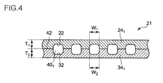
- FIG.4 is a cross-sectional view of a hollow flat plate before bending.
- the hollow curved plate 20 includes a first plate member 24 1 and a second plate member 34 1 .
- the first plate member 24 1 has a first groove 22 formed therein.
- the second plate member 34 1 has a second groove 32 formed therein and is arranged on an inner side of the first plate member 24 1 .
- Each of the hollow parts 40 1 is formed into a linear channel where the cooling air flows.
- the hollow curved plate 20 can be obtained by bending a hollow flat plate 21 illustrated in FIG.4 into a curved shape through press forming.
- the shape of the hollow curved plate 20 in cross-section may be an annular shape continuing annularly in the circumferential direction of the combustor, or may be an arc shape which is split in the circumferential direction of the combustor.
- the combustor basket 12 or the transition piece 14 can be formed by one hollow curved plate 20.
- the combustor basket 12 or the transition piece 14 can be formed by connecting a plurality of the hollow curved plates 20.
- heat-resisting materials such as SUS material, and nickel-based alloys (Hastelloy and Tomilloy, both registered trademark), for instance.
- a plurality of air suction holes 28 is provided in the first plate member 24 1 and a plurality of air discharge holes 29 is provided in the second plate member 34 1 .
- the air suction holes 28 and the air discharge holes 29 each are bigger in diameter than the width of the hollow part 40 1 and open to at least one hollow part 40 1 .
- the cooling air flowing outside the first plate member 24 1 enters the hollow part 40 1 from the air suction holes 28 of the first plate member 24 1 . Then, the cooling air flows through the hollow part 40 1 and is discharged from the air discharge holes 29 of the second plate member 34 1 .
- the cooling air discharged from the air discharge holes 29 mixes in the combustion gas flowing inside the second plate member 34 1 and flows with the combustion gas toward the turbine 6.
- the hollow flat plate 21 is manufactured, as illustrated in FIG.4 , by bonding the first plate member 24 1 and the second plate member 34 1 .
- a width W 1 of the first groove 22 of the first plate member 24 1 is approximately the same as a width W 2 of the second groove 32 of the second plate member 34 1 .
- the first groove 22 faces the second groove 32 such that the position of the first groove 22 coincides with the position of the second groove 32 in the width direction. In this manner, the hollow part 40 1 is formed by the first groove 22 and the second groove 32.
- the shape of the hollow part 40 1 may be arbitrarily adjusted by adjusting a shape of a tool for cutting the first groove 22 and the second groove 32.
- FIG.5A and FIG.5B show examples of the shape of the hollow part 40 1 .
- an angle ⁇ formed by a tangent line L 1 of the first groove 22 and a tangent line L 2 of the second groove 32 at a position 44 corresponding to edges of the grooves (22, 32) in a bond interface 42 between the first plate member 24 1 and the second plate member 34 1 is 180 degrees.
- the angle ⁇ formed by the tangent line L 1 of the first groove 22 and the tangent line L 2 of the second groove 32 at the position 44 is greater than 180 degrees. That is to say, as illustrated in FIG.5A and FIG.5B , the angle ⁇ formed by the tangent line L 1 of the first groove 22 and the tangent line L 2 of the second groove 32 at the position 44 may be set to 180 degrees or greater.
- the tangent line L 1 of the first groove 22 is, to be specific, a tangent line of the first groove 22 extending from the position 44 toward the first plate member 24 1 .
- the tangent line L 2 of the second groove 32 is, to be specific, a tangent line of the second groove 32 extending from the position 44 toward the second plate member 34 1 .
- the first groove 22 and the second groove 32 are rounded into a surface that has no part whose shape is discontinuous (a corner which causes a sudden shape change), thereby preventing stress concentration on the discontinuous-shape part. Both end edges of the first groove 22 and the second groove 32 may be chamfered.
- T 1 is a thickness of the first plate member 24 1 and T 2 is a thickness of the second plate member 34 1 (see FIG.4 ). It is particularly preferable that the thickness T 1 of the first plate member 24 1 is approximately the same as the thickness T 2 of the second plate member 34 1 .
- the bond interface 42 between the first plate member 24 1 and the second plate member 34 1 is arranged closer to a neutral axis of deformation during bending, and thus generation of cracks near the bond interface 42 during the bending is effectively suppressed.
- first plate member 24 1 and the second plate member 34 1 have approximately the same shape. More specifically, the thickness T 1 of the first plate member 24 1 is approximately the same as the thickness T 2 of the second plate member 34 1 , the first groove 22 and the second groove 32 have approximately the same shape, and the first groove 22 and the second groove 32 are arranged approximately at the same position.
- the first plate member 24 1 and the second plate member 34 1 can be communalized and the production cost can be reduced. Further, as the first plate member 24 1 and the second plate member 34 1 are not confused one with the other, it is possible to effectively conduct a manufacturing operation of the hollow curved plate 20.
- the first plate member 24 1 and the second plate member 34 1 are bonded by diffusion bonding. More specifically, the first plate member 24 1 and the second plate member 34 1 are bonded using any one of liquid phase diffusion bonding which uses an insert metal, solid phase diffusion bonding which uses an insert metal, and solid phase diffusion bonding which does not use an insert metal.
- the solid phase diffusion bonding which does not use an insert metal is preferable from the standpoint of improving formability of the hollow curved plate 20 during the bending operation, as it does not cause embrittlement of the base material attributable to the melting-point-lowering element derived from the insert metal.
- the solid phase diffusion bonding which does not use the insert metal there is no blocking of the hollow part by the melted insert metal and thus, it is possible to easily form the hollow part 40 1 of a desired shape.
- the insert metal which is made of a different material from that of the first plate member 24 1 or the second plate member 34 1 is not used, the first plate member 24 1 and the second plate member 34 1 become more recyclable.
- the inserting metal is not used, it is possible to skip a step of arranging the insert metal between the first plate member 24 1 and the second plate member 34 1 .
- first plate member 24 1 and the second plate member 34 1 are made of a homogeneous metal, as bonding conditions of the solid phase diffusion bonding without using the insert metal, it is possible to set the temperature to 60 to 75% of a melting point (°C) of the first plate member 24 1 and the second plate member 34 1 , and to use a mean contact pressure of pressing of 3 to 18MPa.
- the first plate member 24 1 and the second plate member 34 1 may be bonded by solid phase diffusion bonding which does not use an insert metal while pressing the first plate member 24 1 and the second plate member 34 1 at a mean contact pressure of 3 to 18MPa and maintaining the temperature at 1000 to 1150°C.
- FIG.6A to FIG.6C illustrate the positioning of the first plate member 24 1 and the second plate member 34 1 .
- positioning holes (26, 36) are formed at ends on both sides of the grooves (22, 32) of the first plate member 24 1 and the second plate member 34 1 (preferably in four corners of the first plate member 24 1 and the second plate member 34 1 ). Then, a pin 46 is inserted in these positioning holes (26, 36). As a result, the positioning of the first plate member 24 1 and the second plate member 34 1 is performed and the position of the first groove 22 substantially coincides with the position of the second groove 32 in the width direction.
- depressions 27 are formed on a surface contacting the second plate member 34 1 at ends on both sides of the grooves 22 of the first plate member 24 1 .
- projections 37 are formed on a surface contacting the first plate member 24 1 at ends on both sides of the grooves 32 of the second plate member 34 1 . Then, the projections 37 of the second plate member 34 1 are fitted in the depression 27 of the first plate member 24 1 so that the position of the first groove 22 substantially coincides with the position of the second groove 32 in the width direction.
- the projection may be provided in the first plate member 24 1
- the depression may be provided in the second plate 34 1 so that the projection in the first plate member 24 1 is fitted in the depression in the second plate 34 1 .
- the first plate member 24 1 and the second plate member 34 1 are overlapped within a positioning frame 48 manufactured to fit the size of the first plate member 24 1 and the second plate member 34 1 .
- the positioning of the first plate member 24 1 and the second plate member 34 1 is performed and the position of the first groove 22 substantially coincides with the position of the second groove 32 in the width direction.
- the hollow curved plate 20 of this embodiment includes the first plate member 24 1 having the first groove 22 and the second plate member 34 1 having the second groove 32 of the same width as the first groove 22 and bonded to the first plate member 24 1 by diffusion bonding. Further, the hollow curved plate 20 is formed of the first plate member 24 1 and the second plate member 34 1 curved by bending in a state where the first plate member 24 1 and the second plate member 34 1 are bonded together. Then, the first groove 22 faces the second groove 32, the position of the first groove 22 substantially coincides with the position of the second groove 32 in the width direction, and the hollow part 40 1 is formed by the first groove 22 and the second groove 32.
- the hollow part 40 1 is formed of the first groove 22 and the second groove 32 so that the position of the first groove 22 of the first plate member 24 1 substantially coincides with the position of the second groove 32 of the second plate member 34 1 in the width direction, the second groove 32 having approximately the same width as the first groove 22. Therefore, it is possible to avoid formation of the corners which could cause stress concentration. This suppresses generation of cracks during the bending operation and in the usage environment.
- the hollow curved plate as a component of a ring segment of the gas turbine is described.
- a hollow curved plate 50 of this embodiment has substantially the same configuration and manufacturing procedure as the hollow curved plate 20 of the first embodiment, except that the first plate member, the second plate member and the hollow part are shaped differently.
- the same reference numerals are given without adding explanations for those configurations that are the same as the hollow curved plate 20, and mainly the configuration of the hollow curved plate 50 that is different from the hollow curved plate 20 is explained.
- FIG.7 is an illustration of a peripheral configuration of the ring segment of the gas turbine.
- FIG.8A is a cross-sectional view of the ring segment of the gas turbine along the radial direction of the rotor.
- FIG.8B is an enlarged view of section A of FIG.8A .
- a plurality of ring segments 49 having inside a hollow part 40 2 for cooling and shaped into an arc in cross-section is arranged in the circumferential direction of the rotor to form a wall of a combustion gas channel as illustrated in FIG.7 .
- a channel 52 is formed in a blade ring 51.
- the channel 52 opens toward the ring segment 49 and the cooling air flows inside the channel 52.
- an isolation ring 53 is fixed to the blade ring 51. And to this isolation ring 53, the ring segment 49 and an impingement plate 54 are attached.
- the impingement plate 54 is arranged between the blade ring 51 and the ring segment 49.
- the impingement plate 54 is configured to eject the cooling air supplied from the channel 52 toward the ring segment 49 by means of a plurality of through-holes 55, thereby cooling the ring segment 49 from outside. Further, the cooling air enters the hollow part 40 2 provided in the ring segment 49, thereby cooling the ring segment 49 from inside.
- the hollow part 40 2 opens to an outer circumferential surface of the ring segment 49 at an upstream end in an axial direction of the rotor, and opens to an end surface of the ring segment 49 at a downstream end in the axial direction of the rotor.
- the ring segment 49 includes flanges 56 on an upstream side and a downstream side in the axial direction of the rotor, and is attached to the isolation ring 53 via this flange 56.
- G indicates a flow direction of the combustion gas, and the left side in the drawing is the upstream side in the axial direction of the rotor while the right side in the drawing is the downstream side in the axial direction of the rotor.
- a plurality of the ring segments 49 is arranged in the circumferential direction of the rotor, and a seal member 57 is provided between adjacent two of the ring segments 49.
- the seal member 57 is configured to prevent leaking of the combustion gas through a gap between adjacent two of the ring segments 49.
- the seal member 57 is fitted in a groove 59 provided on both ends 58 of the ring segment 49 in the circumferential direction of the rotor.
- the hollow curved plate 50 forming the ring segment 49 includes a first plate member 24 2 and a second plate member 34 2 .
- the first plate member 24 2 has the first groove 22.
- the second plate member 34 2 has the second groove 32 which has almost the same width as the first groove 22.
- the second plate member 34 2 is bonded to the first plate member 24 2 by diffusion bonding. In this case, bonding of the first plate member 24 2 and the second plate member 34 2 is performed so that the first groove 22 faces the second groove 32 and the position of the first groove 22 substantially coincides with the position of the second groove 32 in the width direction, and the hollow part 40 2 is formed by the first groove 22 and the second groove 32.
- the curved shape of the hollow curved plate 50 is formed by bending in the state where the first plate member 24 2 and the second plate member 34 2 are bonded together.
- a nozzle skirt of a rocket engine includes a cooling channel for a cooling medium (liquid hydrogen) to flow therethrough.
- a cooling medium liquid hydrogen
- a hollow curved plate 70 of this embodiment has substantially the same configuration and manufacturing procedure as the hollow curved plate 20 of the first embodiment, except that the first plate member, the second plate member and the hollow part are shaped differently.
- the same reference numerals are given without adding explanations for those configurations that are the same as the hollow curved plate 20, and mainly the configuration of the hollow curved plate 70 that is different from the hollow curved plate 20 is explained.
- FIG.9 is an oblique view of a configuration example of the nozzle skirt of the rocket engine.
- FIG.10 is a fragmentary illustration of a cross-section of the nozzle skirt along line B-B of FIG.9 .
- a nozzle skirt 71 has a cylindrical shape (a cylindrical shape with a side face inclined with respect to a center axis), and a plurality of hollow parts 403 as a cooling channel is provided inside the nozzle skirt 71.
- the hollow part 403 is a linear or spiral channel extending in the longitudinal direction of the nozzle skirt 71. Each end of the hollow part 403 opens to an end surface in the longitudinal direction of the nozzle skirt 71.
- the hollow curved plate 70 forming the nozzle skirt 71 includes a first plate member 243 and a second plate member 343.
- the first plate member 243 has the first groove 22.
- the second plate member 343 has the second groove 32 which has almost the same width as the first groove 22.
- the second plate member 343 is bonded to the first plate member 243 by diffusion bonding. In this case, bonding of the first plate member 243 and the second plate member 343 is performed so that the first groove 22 faces the second groove 32 and the position of the first groove 22 substantially coincides with the position of the second groove 32 in the width direction, and the hollow part 403 is formed by the first groove 22 and the second groove 32.
- the curved shape of the hollow curved plate 70 is formed by bending in the state where the first plate member 243 and the second plate member 343 are bonded together.
- the hollow curved plates (20, 50, 70) are used as components of the gas turbine combustor, of the ring segment of the gas turbine, and of the nozzle skirt of the rocket engine, respectively.
- applications of the hollow curved plate according to the present invention are not particularly limited, as long as the hollow curved plate is formed of the hollow flat plate with the hollow part curved by bending.
- the air is used as cooling medium for cooling the combustor or the ring segment of the gas turbine.
- steam may also be used, and thus the cooling medium is not particularly limited.
Landscapes
- Engineering & Computer Science (AREA)
- Mechanical Engineering (AREA)
- Chemical & Material Sciences (AREA)
- Combustion & Propulsion (AREA)
- General Engineering & Computer Science (AREA)
- Aviation & Aerospace Engineering (AREA)
- Turbine Rotor Nozzle Sealing (AREA)
- Pressure Welding/Diffusion-Bonding (AREA)
Applications Claiming Priority (2)
| Application Number | Priority Date | Filing Date | Title |
|---|---|---|---|
| JP2011115655 | 2011-05-24 | ||
| PCT/JP2012/062873 WO2012161142A1 (ja) | 2011-05-24 | 2012-05-18 | 中空湾曲板及びその製造方法ならびにガスタービンの燃焼器 |
Publications (3)
| Publication Number | Publication Date |
|---|---|
| EP2716396A1 true EP2716396A1 (de) | 2014-04-09 |
| EP2716396A4 EP2716396A4 (de) | 2014-12-24 |
| EP2716396B1 EP2716396B1 (de) | 2020-09-09 |
Family
ID=47217219
Family Applications (1)
| Application Number | Title | Priority Date | Filing Date |
|---|---|---|---|
| EP12789220.6A Not-in-force EP2716396B1 (de) | 2011-05-24 | 2012-05-18 | Hohle gekrümmte platte, herstellungsverfahren dafür und brenner für eine gasturbine |
Country Status (6)
| Country | Link |
|---|---|
| US (1) | US20140290255A1 (de) |
| EP (1) | EP2716396B1 (de) |
| JP (1) | JPWO2012161142A1 (de) |
| KR (2) | KR101682845B1 (de) |
| CN (1) | CN103459080A (de) |
| WO (1) | WO2012161142A1 (de) |
Cited By (9)
| Publication number | Priority date | Publication date | Assignee | Title |
|---|---|---|---|---|
| FR3059354A1 (fr) * | 2016-11-25 | 2018-06-01 | Airbus Safran Launchers Sas | Carter ameliore pour organe de combustion |
| EP3587927A1 (de) * | 2018-06-28 | 2020-01-01 | United Technologies Corporation | Verfahren zur herstellung eines wärmeschutzpaneels |
| US11255545B1 (en) | 2020-10-26 | 2022-02-22 | General Electric Company | Integrated combustion nozzle having a unified head end |
| US11371702B2 (en) | 2020-08-31 | 2022-06-28 | General Electric Company | Impingement panel for a turbomachine |
| US11460191B2 (en) | 2020-08-31 | 2022-10-04 | General Electric Company | Cooling insert for a turbomachine |
| US11614233B2 (en) | 2020-08-31 | 2023-03-28 | General Electric Company | Impingement panel support structure and method of manufacture |
| US11767766B1 (en) | 2022-07-29 | 2023-09-26 | General Electric Company | Turbomachine airfoil having impingement cooling passages |
| US11994293B2 (en) | 2020-08-31 | 2024-05-28 | General Electric Company | Impingement cooling apparatus support structure and method of manufacture |
| US11994292B2 (en) | 2020-08-31 | 2024-05-28 | General Electric Company | Impingement cooling apparatus for turbomachine |
Families Citing this family (10)
| Publication number | Priority date | Publication date | Assignee | Title |
|---|---|---|---|---|
| US9015944B2 (en) * | 2013-02-22 | 2015-04-28 | General Electric Company | Method of forming a microchannel cooled component |
| DE112014006619B4 (de) * | 2014-04-25 | 2023-11-16 | Mitsubishi Heavy Industries, Ltd. | Gasturbinenbrennkammer und mit selbiger versehene Gasturbine |
| JP6516996B2 (ja) * | 2014-10-10 | 2019-05-22 | 川崎重工業株式会社 | 燃焼器及びガスタービンエンジン |
| JP6404704B2 (ja) * | 2014-12-19 | 2018-10-10 | トクデン株式会社 | 流体加熱装置 |
| JP6341614B2 (ja) * | 2014-12-19 | 2018-06-13 | トクデン株式会社 | 流体加熱装置 |
| WO2018026381A1 (en) * | 2016-08-03 | 2018-02-08 | Siemens Aktiengesellschaft | Combustion system with injector assemblies arranged to recapture cooling air in a combustor wall to form a shielding flow of air in a combustion stage |
| JP6746486B2 (ja) * | 2016-12-14 | 2020-08-26 | 三菱日立パワーシステムズ株式会社 | 分割環及びガスタービン |
| JP7641120B2 (ja) * | 2018-12-21 | 2025-03-06 | 日本発條株式会社 | 接合方法、接合体および流路付きプレート |
| CN114683000B (zh) * | 2021-05-27 | 2023-11-17 | 江苏瑞吉达建材科技有限公司 | 一种耐蚀双曲率铝合金板制备方法 |
| JP7370364B2 (ja) * | 2021-09-30 | 2023-10-27 | 三菱重工業株式会社 | トランジションピース、燃焼器及びガスタービンエンジン |
Family Cites Families (11)
| Publication number | Priority date | Publication date | Assignee | Title |
|---|---|---|---|---|
| GB1503921A (en) * | 1975-12-19 | 1978-03-15 | Rolls Royce | Method of manufacturing combustion chambers for gas turbine engines |
| GB2049152B (en) * | 1979-05-01 | 1983-05-18 | Rolls Royce | Perforate laminated material |
| US4302941A (en) * | 1980-04-02 | 1981-12-01 | United Technologies Corporation | Combuster liner construction for gas turbine engine |
| US4513732A (en) * | 1981-11-10 | 1985-04-30 | Feldman Jr Karl T | Passive integral solar heat collector system |
| JP2548130B2 (ja) * | 1986-01-20 | 1996-10-30 | 三菱マテリアル株式会社 | 焼結合金部材の接合方法 |
| GB2192705B (en) * | 1986-07-18 | 1990-06-06 | Rolls Royce Plc | Porous sheet structure for a combustion chamber |
| JP3192690B2 (ja) | 1991-08-13 | 2001-07-30 | 三菱重工業株式会社 | ガスタービン燃焼器の内筒 |
| JP2003201863A (ja) * | 2001-10-29 | 2003-07-18 | Mitsubishi Heavy Ind Ltd | 燃焼器及びこれを備えたガスタービン |
| JP4823186B2 (ja) * | 2007-09-25 | 2011-11-24 | 三菱重工業株式会社 | ガスタービン燃焼器 |
| JP4768763B2 (ja) * | 2008-02-07 | 2011-09-07 | 川崎重工業株式会社 | 二重壁冷却型のガスタービン燃焼器の冷却構造 |
| JP4929372B2 (ja) * | 2010-06-02 | 2012-05-09 | 株式会社東芝 | 導波管ダイプレクサ及び導波管 |
-
2012
- 2012-05-18 KR KR1020157014673A patent/KR101682845B1/ko not_active Expired - Fee Related
- 2012-05-18 EP EP12789220.6A patent/EP2716396B1/de not_active Not-in-force
- 2012-05-18 US US14/009,004 patent/US20140290255A1/en not_active Abandoned
- 2012-05-18 JP JP2013516356A patent/JPWO2012161142A1/ja active Pending
- 2012-05-18 KR KR1020137024139A patent/KR20130116948A/ko not_active Ceased
- 2012-05-18 CN CN2012800170247A patent/CN103459080A/zh active Pending
- 2012-05-18 WO PCT/JP2012/062873 patent/WO2012161142A1/ja not_active Ceased
Cited By (10)
| Publication number | Priority date | Publication date | Assignee | Title |
|---|---|---|---|---|
| FR3059354A1 (fr) * | 2016-11-25 | 2018-06-01 | Airbus Safran Launchers Sas | Carter ameliore pour organe de combustion |
| EP3587927A1 (de) * | 2018-06-28 | 2020-01-01 | United Technologies Corporation | Verfahren zur herstellung eines wärmeschutzpaneels |
| US11035572B2 (en) | 2018-06-28 | 2021-06-15 | Raytheon Technologies Corporation | Heat shield panel manufacturing process |
| US11371702B2 (en) | 2020-08-31 | 2022-06-28 | General Electric Company | Impingement panel for a turbomachine |
| US11460191B2 (en) | 2020-08-31 | 2022-10-04 | General Electric Company | Cooling insert for a turbomachine |
| US11614233B2 (en) | 2020-08-31 | 2023-03-28 | General Electric Company | Impingement panel support structure and method of manufacture |
| US11994293B2 (en) | 2020-08-31 | 2024-05-28 | General Electric Company | Impingement cooling apparatus support structure and method of manufacture |
| US11994292B2 (en) | 2020-08-31 | 2024-05-28 | General Electric Company | Impingement cooling apparatus for turbomachine |
| US11255545B1 (en) | 2020-10-26 | 2022-02-22 | General Electric Company | Integrated combustion nozzle having a unified head end |
| US11767766B1 (en) | 2022-07-29 | 2023-09-26 | General Electric Company | Turbomachine airfoil having impingement cooling passages |
Also Published As
| Publication number | Publication date |
|---|---|
| EP2716396A4 (de) | 2014-12-24 |
| WO2012161142A1 (ja) | 2012-11-29 |
| JPWO2012161142A1 (ja) | 2014-07-31 |
| EP2716396B1 (de) | 2020-09-09 |
| KR20130116948A (ko) | 2013-10-24 |
| KR101682845B1 (ko) | 2016-12-05 |
| CN103459080A (zh) | 2013-12-18 |
| KR20150067402A (ko) | 2015-06-17 |
| US20140290255A1 (en) | 2014-10-02 |
Similar Documents
| Publication | Publication Date | Title |
|---|---|---|
| EP2716396B1 (de) | Hohle gekrümmte platte, herstellungsverfahren dafür und brenner für eine gasturbine | |
| CN110857629B (zh) | 用于涡轮发动机的具有冷却特性的花键密封件 | |
| EP2669579B1 (de) | Turbomaschinenbrennkammerdüse mit einer monolithischen Düsenkomponente und Erzeugungsverfahren dafür | |
| JP4454993B2 (ja) | 冷却を改善した二重壁燃焼器ライナセグメント | |
| US20110302929A1 (en) | Exhaust gas housing for a gas turbine and method for producing same | |
| US9194258B2 (en) | Gas turbine engine case bosses | |
| US8215904B2 (en) | Assembling method of stator blade ring segment, stator blade ring segment, coupling member, welding method | |
| US10655489B2 (en) | Systems and methods for assembling flow path components | |
| CN103764974A (zh) | 燃烧器的尾筒、具备该尾筒的燃气轮机及尾筒的制造方法 | |
| JP2013245675A (ja) | 高温ガス経路部品を製造する方法 | |
| JP2006170204A (ja) | タービンノズルセグメント及びその修理方法 | |
| EP3009605B1 (de) | Hochtemperaturbauteil einer gasturbine, gasturbine damit und verfahren zur herstellung eines hochtemperaturbauteils einer gasturbine | |
| US11319879B2 (en) | Manufacturing method of turbine casing | |
| JP2002295268A (ja) | ガスタービン燃焼器ライナー構造とその補修方法 | |
| JP2005002899A (ja) | ガスタービン燃焼器 | |
| KR101960199B1 (ko) | 연소기의 실린더, 연소기의 실린더의 제조 방법 및 압력 용기 | |
| JP5885935B2 (ja) | タービン静翼およびガスタービン | |
| RU2688124C2 (ru) | Способ для изготовления узла турбины | |
| EP3967846B1 (de) | Leitschaufelsegment, dampfturbine mit einer leitschaufelreihe aus mehreren düsensegmenten und verfahren zu deren zusammenbau | |
| US11174753B2 (en) | Guide vane for a turbomachine | |
| US12234743B2 (en) | Method for manufacturing a blade for a gas turbine, turbine blade and gas turbine | |
| US20240360765A1 (en) | Method for manufacturing a blade for a gas turbine, turbine blade, and gas turbine |
Legal Events
| Date | Code | Title | Description |
|---|---|---|---|
| PUAI | Public reference made under article 153(3) epc to a published international application that has entered the european phase |
Free format text: ORIGINAL CODE: 0009012 |
|
| 17P | Request for examination filed |
Effective date: 20130905 |
|
| AK | Designated contracting states |
Kind code of ref document: A1 Designated state(s): AL AT BE BG CH CY CZ DE DK EE ES FI FR GB GR HR HU IE IS IT LI LT LU LV MC MK MT NL NO PL PT RO RS SE SI SK SM TR |
|
| DAX | Request for extension of the european patent (deleted) | ||
| A4 | Supplementary search report drawn up and despatched |
Effective date: 20141121 |
|
| RIC1 | Information provided on ipc code assigned before grant |
Ipc: B21D 5/06 20060101AFI20141117BHEP Ipc: B23K 20/02 20060101ALI20141117BHEP Ipc: F02C 7/00 20060101ALI20141117BHEP Ipc: B23K 1/00 20060101ALI20141117BHEP Ipc: F23R 3/06 20060101ALI20141117BHEP Ipc: B21D 53/92 20060101ALI20141117BHEP Ipc: F02C 7/18 20060101ALI20141117BHEP Ipc: F23R 3/00 20060101ALI20141117BHEP Ipc: F01D 11/08 20060101ALI20141117BHEP |
|
| RAP1 | Party data changed (applicant data changed or rights of an application transferred) |
Owner name: MITSUBISHI HITACHI POWER SYSTEMS, LTD. |
|
| 17Q | First examination report despatched |
Effective date: 20160811 |
|
| STAA | Information on the status of an ep patent application or granted ep patent |
Free format text: STATUS: EXAMINATION IS IN PROGRESS |
|
| REG | Reference to a national code |
Ref country code: DE Ref legal event code: R079 Ref document number: 602012072256 Country of ref document: DE Free format text: PREVIOUS MAIN CLASS: B23K0020000000 Ipc: B21D0005060000 |
|
| RIC1 | Information provided on ipc code assigned before grant |
Ipc: B23K 1/00 20060101ALI20200401BHEP Ipc: F02C 7/18 20060101ALI20200401BHEP Ipc: B23K 101/00 20060101ALI20200401BHEP Ipc: F23R 3/06 20060101ALI20200401BHEP Ipc: B21D 53/92 20060101ALI20200401BHEP Ipc: F01D 11/08 20060101ALI20200401BHEP Ipc: B23K 20/02 20060101ALI20200401BHEP Ipc: F02C 7/00 20060101ALI20200401BHEP Ipc: F23R 3/00 20060101ALI20200401BHEP Ipc: B21D 5/06 20060101AFI20200401BHEP |
|
| GRAP | Despatch of communication of intention to grant a patent |
Free format text: ORIGINAL CODE: EPIDOSNIGR1 |
|
| STAA | Information on the status of an ep patent application or granted ep patent |
Free format text: STATUS: GRANT OF PATENT IS INTENDED |
|
| INTG | Intention to grant announced |
Effective date: 20200526 |
|
| GRAS | Grant fee paid |
Free format text: ORIGINAL CODE: EPIDOSNIGR3 |
|
| GRAA | (expected) grant |
Free format text: ORIGINAL CODE: 0009210 |
|
| STAA | Information on the status of an ep patent application or granted ep patent |
Free format text: STATUS: THE PATENT HAS BEEN GRANTED |
|
| AK | Designated contracting states |
Kind code of ref document: B1 Designated state(s): AL AT BE BG CH CY CZ DE DK EE ES FI FR GB GR HR HU IE IS IT LI LT LU LV MC MK MT NL NO PL PT RO RS SE SI SK SM TR |
|
| REG | Reference to a national code |
Ref country code: GB Ref legal event code: FG4D |
|
| REG | Reference to a national code |
Ref country code: AT Ref legal event code: REF Ref document number: 1310919 Country of ref document: AT Kind code of ref document: T Effective date: 20200915 Ref country code: CH Ref legal event code: EP |
|
| REG | Reference to a national code |
Ref country code: IE Ref legal event code: FG4D |
|
| REG | Reference to a national code |
Ref country code: DE Ref legal event code: R096 Ref document number: 602012072256 Country of ref document: DE |
|
| REG | Reference to a national code |
Ref country code: DE Ref legal event code: R082 Ref document number: 602012072256 Country of ref document: DE Representative=s name: BARDEHLE PAGENBERG PARTNERSCHAFT MBB PATENTANW, DE Ref country code: DE Ref legal event code: R081 Ref document number: 602012072256 Country of ref document: DE Owner name: MITSUBISHI POWER, LTD., YOKOHAMA-SHI, JP Free format text: FORMER OWNER: MITSUBISHI HITACHI POWER SYSTEMS, LTD., YOKOHAMA-SHI, KANAGAWA, JP |
|
| REG | Reference to a national code |
Ref country code: LT Ref legal event code: MG4D |
|
| PG25 | Lapsed in a contracting state [announced via postgrant information from national office to epo] |
Ref country code: GR Free format text: LAPSE BECAUSE OF FAILURE TO SUBMIT A TRANSLATION OF THE DESCRIPTION OR TO PAY THE FEE WITHIN THE PRESCRIBED TIME-LIMIT Effective date: 20201210 Ref country code: LT Free format text: LAPSE BECAUSE OF FAILURE TO SUBMIT A TRANSLATION OF THE DESCRIPTION OR TO PAY THE FEE WITHIN THE PRESCRIBED TIME-LIMIT Effective date: 20200909 Ref country code: BG Free format text: LAPSE BECAUSE OF FAILURE TO SUBMIT A TRANSLATION OF THE DESCRIPTION OR TO PAY THE FEE WITHIN THE PRESCRIBED TIME-LIMIT Effective date: 20201209 Ref country code: SE Free format text: LAPSE BECAUSE OF FAILURE TO SUBMIT A TRANSLATION OF THE DESCRIPTION OR TO PAY THE FEE WITHIN THE PRESCRIBED TIME-LIMIT Effective date: 20200909 Ref country code: NO Free format text: LAPSE BECAUSE OF FAILURE TO SUBMIT A TRANSLATION OF THE DESCRIPTION OR TO PAY THE FEE WITHIN THE PRESCRIBED TIME-LIMIT Effective date: 20201209 Ref country code: HR Free format text: LAPSE BECAUSE OF FAILURE TO SUBMIT A TRANSLATION OF THE DESCRIPTION OR TO PAY THE FEE WITHIN THE PRESCRIBED TIME-LIMIT Effective date: 20200909 Ref country code: FI Free format text: LAPSE BECAUSE OF FAILURE TO SUBMIT A TRANSLATION OF THE DESCRIPTION OR TO PAY THE FEE WITHIN THE PRESCRIBED TIME-LIMIT Effective date: 20200909 |
|
| REG | Reference to a national code |
Ref country code: AT Ref legal event code: MK05 Ref document number: 1310919 Country of ref document: AT Kind code of ref document: T Effective date: 20200909 |
|
| REG | Reference to a national code |
Ref country code: NL Ref legal event code: MP Effective date: 20200909 |
|
| PG25 | Lapsed in a contracting state [announced via postgrant information from national office to epo] |
Ref country code: RS Free format text: LAPSE BECAUSE OF FAILURE TO SUBMIT A TRANSLATION OF THE DESCRIPTION OR TO PAY THE FEE WITHIN THE PRESCRIBED TIME-LIMIT Effective date: 20200909 Ref country code: LV Free format text: LAPSE BECAUSE OF FAILURE TO SUBMIT A TRANSLATION OF THE DESCRIPTION OR TO PAY THE FEE WITHIN THE PRESCRIBED TIME-LIMIT Effective date: 20200909 Ref country code: PL Free format text: LAPSE BECAUSE OF FAILURE TO SUBMIT A TRANSLATION OF THE DESCRIPTION OR TO PAY THE FEE WITHIN THE PRESCRIBED TIME-LIMIT Effective date: 20200909 |
|
| PG25 | Lapsed in a contracting state [announced via postgrant information from national office to epo] |
Ref country code: SM Free format text: LAPSE BECAUSE OF FAILURE TO SUBMIT A TRANSLATION OF THE DESCRIPTION OR TO PAY THE FEE WITHIN THE PRESCRIBED TIME-LIMIT Effective date: 20200909 Ref country code: RO Free format text: LAPSE BECAUSE OF FAILURE TO SUBMIT A TRANSLATION OF THE DESCRIPTION OR TO PAY THE FEE WITHIN THE PRESCRIBED TIME-LIMIT Effective date: 20200909 Ref country code: NL Free format text: LAPSE BECAUSE OF FAILURE TO SUBMIT A TRANSLATION OF THE DESCRIPTION OR TO PAY THE FEE WITHIN THE PRESCRIBED TIME-LIMIT Effective date: 20200909 Ref country code: PT Free format text: LAPSE BECAUSE OF FAILURE TO SUBMIT A TRANSLATION OF THE DESCRIPTION OR TO PAY THE FEE WITHIN THE PRESCRIBED TIME-LIMIT Effective date: 20210111 Ref country code: EE Free format text: LAPSE BECAUSE OF FAILURE TO SUBMIT A TRANSLATION OF THE DESCRIPTION OR TO PAY THE FEE WITHIN THE PRESCRIBED TIME-LIMIT Effective date: 20200909 Ref country code: CZ Free format text: LAPSE BECAUSE OF FAILURE TO SUBMIT A TRANSLATION OF THE DESCRIPTION OR TO PAY THE FEE WITHIN THE PRESCRIBED TIME-LIMIT Effective date: 20200909 |
|
| PG25 | Lapsed in a contracting state [announced via postgrant information from national office to epo] |
Ref country code: AL Free format text: LAPSE BECAUSE OF FAILURE TO SUBMIT A TRANSLATION OF THE DESCRIPTION OR TO PAY THE FEE WITHIN THE PRESCRIBED TIME-LIMIT Effective date: 20200909 Ref country code: AT Free format text: LAPSE BECAUSE OF FAILURE TO SUBMIT A TRANSLATION OF THE DESCRIPTION OR TO PAY THE FEE WITHIN THE PRESCRIBED TIME-LIMIT Effective date: 20200909 Ref country code: ES Free format text: LAPSE BECAUSE OF FAILURE TO SUBMIT A TRANSLATION OF THE DESCRIPTION OR TO PAY THE FEE WITHIN THE PRESCRIBED TIME-LIMIT Effective date: 20200909 Ref country code: IS Free format text: LAPSE BECAUSE OF FAILURE TO SUBMIT A TRANSLATION OF THE DESCRIPTION OR TO PAY THE FEE WITHIN THE PRESCRIBED TIME-LIMIT Effective date: 20210109 |
|
| REG | Reference to a national code |
Ref country code: DE Ref legal event code: R097 Ref document number: 602012072256 Country of ref document: DE |
|
| PG25 | Lapsed in a contracting state [announced via postgrant information from national office to epo] |
Ref country code: SK Free format text: LAPSE BECAUSE OF FAILURE TO SUBMIT A TRANSLATION OF THE DESCRIPTION OR TO PAY THE FEE WITHIN THE PRESCRIBED TIME-LIMIT Effective date: 20200909 |
|
| PLBE | No opposition filed within time limit |
Free format text: ORIGINAL CODE: 0009261 |
|
| STAA | Information on the status of an ep patent application or granted ep patent |
Free format text: STATUS: NO OPPOSITION FILED WITHIN TIME LIMIT |
|
| 26N | No opposition filed |
Effective date: 20210610 |
|
| PG25 | Lapsed in a contracting state [announced via postgrant information from national office to epo] |
Ref country code: SI Free format text: LAPSE BECAUSE OF FAILURE TO SUBMIT A TRANSLATION OF THE DESCRIPTION OR TO PAY THE FEE WITHIN THE PRESCRIBED TIME-LIMIT Effective date: 20200909 Ref country code: DK Free format text: LAPSE BECAUSE OF FAILURE TO SUBMIT A TRANSLATION OF THE DESCRIPTION OR TO PAY THE FEE WITHIN THE PRESCRIBED TIME-LIMIT Effective date: 20200909 |
|
| PG25 | Lapsed in a contracting state [announced via postgrant information from national office to epo] |
Ref country code: IT Free format text: LAPSE BECAUSE OF FAILURE TO SUBMIT A TRANSLATION OF THE DESCRIPTION OR TO PAY THE FEE WITHIN THE PRESCRIBED TIME-LIMIT Effective date: 20200909 |
|
| REG | Reference to a national code |
Ref country code: CH Ref legal event code: PL |
|
| GBPC | Gb: european patent ceased through non-payment of renewal fee |
Effective date: 20210518 |
|
| PG25 | Lapsed in a contracting state [announced via postgrant information from national office to epo] |
Ref country code: CH Free format text: LAPSE BECAUSE OF NON-PAYMENT OF DUE FEES Effective date: 20210531 Ref country code: MC Free format text: LAPSE BECAUSE OF FAILURE TO SUBMIT A TRANSLATION OF THE DESCRIPTION OR TO PAY THE FEE WITHIN THE PRESCRIBED TIME-LIMIT Effective date: 20200909 Ref country code: LI Free format text: LAPSE BECAUSE OF NON-PAYMENT OF DUE FEES Effective date: 20210531 Ref country code: LU Free format text: LAPSE BECAUSE OF NON-PAYMENT OF DUE FEES Effective date: 20210518 |
|
| REG | Reference to a national code |
Ref country code: BE Ref legal event code: MM Effective date: 20210531 |
|
| PG25 | Lapsed in a contracting state [announced via postgrant information from national office to epo] |
Ref country code: IE Free format text: LAPSE BECAUSE OF NON-PAYMENT OF DUE FEES Effective date: 20210518 Ref country code: GB Free format text: LAPSE BECAUSE OF NON-PAYMENT OF DUE FEES Effective date: 20210518 |
|
| PG25 | Lapsed in a contracting state [announced via postgrant information from national office to epo] |
Ref country code: FR Free format text: LAPSE BECAUSE OF NON-PAYMENT OF DUE FEES Effective date: 20210531 |
|
| PG25 | Lapsed in a contracting state [announced via postgrant information from national office to epo] |
Ref country code: BE Free format text: LAPSE BECAUSE OF NON-PAYMENT OF DUE FEES Effective date: 20210531 |
|
| PG25 | Lapsed in a contracting state [announced via postgrant information from national office to epo] |
Ref country code: HU Free format text: LAPSE BECAUSE OF FAILURE TO SUBMIT A TRANSLATION OF THE DESCRIPTION OR TO PAY THE FEE WITHIN THE PRESCRIBED TIME-LIMIT; INVALID AB INITIO Effective date: 20120518 Ref country code: CY Free format text: LAPSE BECAUSE OF FAILURE TO SUBMIT A TRANSLATION OF THE DESCRIPTION OR TO PAY THE FEE WITHIN THE PRESCRIBED TIME-LIMIT Effective date: 20200909 |
|
| PGFP | Annual fee paid to national office [announced via postgrant information from national office to epo] |
Ref country code: DE Payment date: 20230331 Year of fee payment: 12 |
|
| PG25 | Lapsed in a contracting state [announced via postgrant information from national office to epo] |
Ref country code: MK Free format text: LAPSE BECAUSE OF FAILURE TO SUBMIT A TRANSLATION OF THE DESCRIPTION OR TO PAY THE FEE WITHIN THE PRESCRIBED TIME-LIMIT Effective date: 20200909 |
|
| PG25 | Lapsed in a contracting state [announced via postgrant information from national office to epo] |
Ref country code: MT Free format text: LAPSE BECAUSE OF FAILURE TO SUBMIT A TRANSLATION OF THE DESCRIPTION OR TO PAY THE FEE WITHIN THE PRESCRIBED TIME-LIMIT Effective date: 20200909 |
|
| REG | Reference to a national code |
Ref country code: DE Ref legal event code: R119 Ref document number: 602012072256 Country of ref document: DE |
|
| PG25 | Lapsed in a contracting state [announced via postgrant information from national office to epo] |
Ref country code: DE Free format text: LAPSE BECAUSE OF NON-PAYMENT OF DUE FEES Effective date: 20241203 |
|
| PG25 | Lapsed in a contracting state [announced via postgrant information from national office to epo] |
Ref country code: TR Free format text: LAPSE BECAUSE OF FAILURE TO SUBMIT A TRANSLATION OF THE DESCRIPTION OR TO PAY THE FEE WITHIN THE PRESCRIBED TIME-LIMIT Effective date: 20200909 |