EP2716542A2 - Appareil de récupération de chaleur et de froid utilisant un combustible de gaz naturel liquéfié et transporteur de gaz liquéfié incluant celui-ci - Google Patents
Appareil de récupération de chaleur et de froid utilisant un combustible de gaz naturel liquéfié et transporteur de gaz liquéfié incluant celui-ci Download PDFInfo
- Publication number
- EP2716542A2 EP2716542A2 EP12793505.4A EP12793505A EP2716542A2 EP 2716542 A2 EP2716542 A2 EP 2716542A2 EP 12793505 A EP12793505 A EP 12793505A EP 2716542 A2 EP2716542 A2 EP 2716542A2
- Authority
- EP
- European Patent Office
- Prior art keywords
- lng
- liquefied gas
- tank
- cold heat
- recovery apparatus
- Prior art date
- Legal status (The legal status is an assumption and is not a legal conclusion. Google has not performed a legal analysis and makes no representation as to the accuracy of the status listed.)
- Withdrawn
Links
Images


Classifications
-
- F—MECHANICAL ENGINEERING; LIGHTING; HEATING; WEAPONS; BLASTING
- F17—STORING OR DISTRIBUTING GASES OR LIQUIDS
- F17C—VESSELS FOR CONTAINING OR STORING COMPRESSED, LIQUEFIED OR SOLIDIFIED GASES; FIXED-CAPACITY GAS-HOLDERS; FILLING VESSELS WITH, OR DISCHARGING FROM VESSELS, COMPRESSED, LIQUEFIED, OR SOLIDIFIED GASES
- F17C9/00—Methods or apparatus for discharging liquefied or solidified gases from vessels not under pressure
- F17C9/02—Methods or apparatus for discharging liquefied or solidified gases from vessels not under pressure with change of state, e.g. vaporisation
- F17C9/04—Recovery of thermal energy
-
- B—PERFORMING OPERATIONS; TRANSPORTING
- B63—SHIPS OR OTHER WATERBORNE VESSELS; RELATED EQUIPMENT
- B63H—MARINE PROPULSION OR STEERING
- B63H21/00—Use of propulsion power plant or units on vessels
- B63H21/38—Apparatus or methods specially adapted for use on marine vessels, for handling power plant or unit liquids, e.g. lubricants, coolants, fuels or the like
-
- B—PERFORMING OPERATIONS; TRANSPORTING
- B63—SHIPS OR OTHER WATERBORNE VESSELS; RELATED EQUIPMENT
- B63J—AUXILIARIES ON VESSELS
- B63J2/00—Arrangements of ventilation, heating, cooling, or air-conditioning
- B63J2/12—Heating; Cooling
- B63J2/14—Heating; Cooling of liquid-freight-carrying tanks
-
- F—MECHANICAL ENGINEERING; LIGHTING; HEATING; WEAPONS; BLASTING
- F02—COMBUSTION ENGINES; HOT-GAS OR COMBUSTION-PRODUCT ENGINE PLANTS
- F02D—CONTROLLING COMBUSTION ENGINES
- F02D19/00—Controlling engines characterised by their use of non-liquid fuels, pluralities of fuels, or non-fuel substances added to the combustible mixtures
- F02D19/02—Controlling engines characterised by their use of non-liquid fuels, pluralities of fuels, or non-fuel substances added to the combustible mixtures peculiar to engines working with gaseous fuels
- F02D19/021—Control of components of the fuel supply system
- F02D19/022—Control of components of the fuel supply system to adjust the fuel pressure, temperature or composition
-
- F—MECHANICAL ENGINEERING; LIGHTING; HEATING; WEAPONS; BLASTING
- F02—COMBUSTION ENGINES; HOT-GAS OR COMBUSTION-PRODUCT ENGINE PLANTS
- F02M—SUPPLYING COMBUSTION ENGINES IN GENERAL WITH COMBUSTIBLE MIXTURES OR CONSTITUENTS THEREOF
- F02M21/00—Apparatus for supplying engines with non-liquid fuels, e.g. gaseous fuels stored in liquid form
- F02M21/02—Apparatus for supplying engines with non-liquid fuels, e.g. gaseous fuels stored in liquid form for gaseous fuels
- F02M21/0218—Details on the gaseous fuel supply system, e.g. tanks, valves, pipes, pumps, rails, injectors or mixers
- F02M21/0221—Fuel storage reservoirs, e.g. cryogenic tanks
- F02M21/0224—Secondary gaseous fuel storages
-
- F—MECHANICAL ENGINEERING; LIGHTING; HEATING; WEAPONS; BLASTING
- F02—COMBUSTION ENGINES; HOT-GAS OR COMBUSTION-PRODUCT ENGINE PLANTS
- F02M—SUPPLYING COMBUSTION ENGINES IN GENERAL WITH COMBUSTIBLE MIXTURES OR CONSTITUENTS THEREOF
- F02M21/00—Apparatus for supplying engines with non-liquid fuels, e.g. gaseous fuels stored in liquid form
- F02M21/02—Apparatus for supplying engines with non-liquid fuels, e.g. gaseous fuels stored in liquid form for gaseous fuels
- F02M21/0218—Details on the gaseous fuel supply system, e.g. tanks, valves, pipes, pumps, rails, injectors or mixers
- F02M21/0287—Details on the gaseous fuel supply system, e.g. tanks, valves, pipes, pumps, rails, injectors or mixers characterised by the transition from liquid to gaseous phase ; Injection in liquid phase; Cooling and low temperature storage
-
- F—MECHANICAL ENGINEERING; LIGHTING; HEATING; WEAPONS; BLASTING
- F25—REFRIGERATION OR COOLING; COMBINED HEATING AND REFRIGERATION SYSTEMS; HEAT PUMP SYSTEMS; MANUFACTURE OR STORAGE OF ICE; LIQUEFACTION SOLIDIFICATION OF GASES
- F25J—LIQUEFACTION, SOLIDIFICATION OR SEPARATION OF GASES OR GASEOUS OR LIQUEFIED GASEOUS MIXTURES BY PRESSURE AND COLD TREATMENT OR BY BRINGING THEM INTO THE SUPERCRITICAL STATE
- F25J1/00—Processes or apparatus for liquefying or solidifying gases or gaseous mixtures
- F25J1/0002—Processes or apparatus for liquefying or solidifying gases or gaseous mixtures characterised by the fluid to be liquefied
- F25J1/0022—Hydrocarbons, e.g. natural gas
- F25J1/0025—Boil-off gases "BOG" from storages
-
- F—MECHANICAL ENGINEERING; LIGHTING; HEATING; WEAPONS; BLASTING
- F25—REFRIGERATION OR COOLING; COMBINED HEATING AND REFRIGERATION SYSTEMS; HEAT PUMP SYSTEMS; MANUFACTURE OR STORAGE OF ICE; LIQUEFACTION SOLIDIFICATION OF GASES
- F25J—LIQUEFACTION, SOLIDIFICATION OR SEPARATION OF GASES OR GASEOUS OR LIQUEFIED GASEOUS MIXTURES BY PRESSURE AND COLD TREATMENT OR BY BRINGING THEM INTO THE SUPERCRITICAL STATE
- F25J1/00—Processes or apparatus for liquefying or solidifying gases or gaseous mixtures
- F25J1/0002—Processes or apparatus for liquefying or solidifying gases or gaseous mixtures characterised by the fluid to be liquefied
- F25J1/0027—Oxides of carbon, e.g. CO2
-
- F—MECHANICAL ENGINEERING; LIGHTING; HEATING; WEAPONS; BLASTING
- F25—REFRIGERATION OR COOLING; COMBINED HEATING AND REFRIGERATION SYSTEMS; HEAT PUMP SYSTEMS; MANUFACTURE OR STORAGE OF ICE; LIQUEFACTION SOLIDIFICATION OF GASES
- F25J—LIQUEFACTION, SOLIDIFICATION OR SEPARATION OF GASES OR GASEOUS OR LIQUEFIED GASEOUS MIXTURES BY PRESSURE AND COLD TREATMENT OR BY BRINGING THEM INTO THE SUPERCRITICAL STATE
- F25J1/00—Processes or apparatus for liquefying or solidifying gases or gaseous mixtures
- F25J1/02—Processes or apparatus for liquefying or solidifying gases or gaseous mixtures requiring the use of refrigeration, e.g. of helium or hydrogen ; Details and kind of the refrigeration system used; Integration with other units or processes; Controlling aspects of the process
- F25J1/0221—Processes or apparatus for liquefying or solidifying gases or gaseous mixtures requiring the use of refrigeration, e.g. of helium or hydrogen ; Details and kind of the refrigeration system used; Integration with other units or processes; Controlling aspects of the process using the cold stored in an external cryogenic component in an open refrigeration loop
-
- F—MECHANICAL ENGINEERING; LIGHTING; HEATING; WEAPONS; BLASTING
- F25—REFRIGERATION OR COOLING; COMBINED HEATING AND REFRIGERATION SYSTEMS; HEAT PUMP SYSTEMS; MANUFACTURE OR STORAGE OF ICE; LIQUEFACTION SOLIDIFICATION OF GASES
- F25J—LIQUEFACTION, SOLIDIFICATION OR SEPARATION OF GASES OR GASEOUS OR LIQUEFIED GASEOUS MIXTURES BY PRESSURE AND COLD TREATMENT OR BY BRINGING THEM INTO THE SUPERCRITICAL STATE
- F25J1/00—Processes or apparatus for liquefying or solidifying gases or gaseous mixtures
- F25J1/02—Processes or apparatus for liquefying or solidifying gases or gaseous mixtures requiring the use of refrigeration, e.g. of helium or hydrogen ; Details and kind of the refrigeration system used; Integration with other units or processes; Controlling aspects of the process
- F25J1/0221—Processes or apparatus for liquefying or solidifying gases or gaseous mixtures requiring the use of refrigeration, e.g. of helium or hydrogen ; Details and kind of the refrigeration system used; Integration with other units or processes; Controlling aspects of the process using the cold stored in an external cryogenic component in an open refrigeration loop
- F25J1/0222—Processes or apparatus for liquefying or solidifying gases or gaseous mixtures requiring the use of refrigeration, e.g. of helium or hydrogen ; Details and kind of the refrigeration system used; Integration with other units or processes; Controlling aspects of the process using the cold stored in an external cryogenic component in an open refrigeration loop in combination with an intermediate heat exchange fluid between the cryogenic component and the fluid to be liquefied
-
- F—MECHANICAL ENGINEERING; LIGHTING; HEATING; WEAPONS; BLASTING
- F25—REFRIGERATION OR COOLING; COMBINED HEATING AND REFRIGERATION SYSTEMS; HEAT PUMP SYSTEMS; MANUFACTURE OR STORAGE OF ICE; LIQUEFACTION SOLIDIFICATION OF GASES
- F25J—LIQUEFACTION, SOLIDIFICATION OR SEPARATION OF GASES OR GASEOUS OR LIQUEFIED GASEOUS MIXTURES BY PRESSURE AND COLD TREATMENT OR BY BRINGING THEM INTO THE SUPERCRITICAL STATE
- F25J1/00—Processes or apparatus for liquefying or solidifying gases or gaseous mixtures
- F25J1/02—Processes or apparatus for liquefying or solidifying gases or gaseous mixtures requiring the use of refrigeration, e.g. of helium or hydrogen ; Details and kind of the refrigeration system used; Integration with other units or processes; Controlling aspects of the process
- F25J1/0243—Start-up or control of the process; Details of the apparatus used; Details of the refrigerant compression system used
- F25J1/0244—Operation; Control and regulation; Instrumentation
-
- B—PERFORMING OPERATIONS; TRANSPORTING
- B63—SHIPS OR OTHER WATERBORNE VESSELS; RELATED EQUIPMENT
- B63J—AUXILIARIES ON VESSELS
- B63J99/00—Subject matter not provided for in other groups of this subclass
- B63J2099/001—Burning of transported goods, e.g. fuel, boil-off or refuse
- B63J2099/003—Burning of transported goods, e.g. fuel, boil-off or refuse of cargo oil or fuel, or of boil-off gases, e.g. for propulsive purposes
-
- F—MECHANICAL ENGINEERING; LIGHTING; HEATING; WEAPONS; BLASTING
- F02—COMBUSTION ENGINES; HOT-GAS OR COMBUSTION-PRODUCT ENGINE PLANTS
- F02M—SUPPLYING COMBUSTION ENGINES IN GENERAL WITH COMBUSTIBLE MIXTURES OR CONSTITUENTS THEREOF
- F02M21/00—Apparatus for supplying engines with non-liquid fuels, e.g. gaseous fuels stored in liquid form
- F02M21/02—Apparatus for supplying engines with non-liquid fuels, e.g. gaseous fuels stored in liquid form for gaseous fuels
- F02M21/0203—Apparatus for supplying engines with non-liquid fuels, e.g. gaseous fuels stored in liquid form for gaseous fuels characterised by the type of gaseous fuel
- F02M21/0215—Mixtures of gaseous fuels; Natural gas; Biogas; Mine gas; Landfill gas
-
- F—MECHANICAL ENGINEERING; LIGHTING; HEATING; WEAPONS; BLASTING
- F17—STORING OR DISTRIBUTING GASES OR LIQUIDS
- F17C—VESSELS FOR CONTAINING OR STORING COMPRESSED, LIQUEFIED OR SOLIDIFIED GASES; FIXED-CAPACITY GAS-HOLDERS; FILLING VESSELS WITH, OR DISCHARGING FROM VESSELS, COMPRESSED, LIQUEFIED, OR SOLIDIFIED GASES
- F17C2205/00—Vessel construction, in particular mounting arrangements, attachments or identifications means
- F17C2205/01—Mounting arrangements
- F17C2205/0123—Mounting arrangements characterised by number of vessels
- F17C2205/0126—One vessel
-
- F—MECHANICAL ENGINEERING; LIGHTING; HEATING; WEAPONS; BLASTING
- F17—STORING OR DISTRIBUTING GASES OR LIQUIDS
- F17C—VESSELS FOR CONTAINING OR STORING COMPRESSED, LIQUEFIED OR SOLIDIFIED GASES; FIXED-CAPACITY GAS-HOLDERS; FILLING VESSELS WITH, OR DISCHARGING FROM VESSELS, COMPRESSED, LIQUEFIED, OR SOLIDIFIED GASES
- F17C2205/00—Vessel construction, in particular mounting arrangements, attachments or identifications means
- F17C2205/01—Mounting arrangements
- F17C2205/0123—Mounting arrangements characterised by number of vessels
- F17C2205/013—Two or more vessels
- F17C2205/0134—Two or more vessels characterised by the presence of fluid connection between vessels
- F17C2205/0142—Two or more vessels characterised by the presence of fluid connection between vessels bundled in parallel
-
- F—MECHANICAL ENGINEERING; LIGHTING; HEATING; WEAPONS; BLASTING
- F17—STORING OR DISTRIBUTING GASES OR LIQUIDS
- F17C—VESSELS FOR CONTAINING OR STORING COMPRESSED, LIQUEFIED OR SOLIDIFIED GASES; FIXED-CAPACITY GAS-HOLDERS; FILLING VESSELS WITH, OR DISCHARGING FROM VESSELS, COMPRESSED, LIQUEFIED, OR SOLIDIFIED GASES
- F17C2205/00—Vessel construction, in particular mounting arrangements, attachments or identifications means
- F17C2205/03—Fluid connections, filters, valves, closure means or other attachments
- F17C2205/0302—Fittings, valves, filters, or components in connection with the gas storage device
- F17C2205/0323—Valves
- F17C2205/0326—Valves electrically actuated
-
- F—MECHANICAL ENGINEERING; LIGHTING; HEATING; WEAPONS; BLASTING
- F17—STORING OR DISTRIBUTING GASES OR LIQUIDS
- F17C—VESSELS FOR CONTAINING OR STORING COMPRESSED, LIQUEFIED OR SOLIDIFIED GASES; FIXED-CAPACITY GAS-HOLDERS; FILLING VESSELS WITH, OR DISCHARGING FROM VESSELS, COMPRESSED, LIQUEFIED, OR SOLIDIFIED GASES
- F17C2221/00—Handled fluid, in particular type of fluid
- F17C2221/01—Pure fluids
- F17C2221/013—Carbon dioxide
-
- F—MECHANICAL ENGINEERING; LIGHTING; HEATING; WEAPONS; BLASTING
- F17—STORING OR DISTRIBUTING GASES OR LIQUIDS
- F17C—VESSELS FOR CONTAINING OR STORING COMPRESSED, LIQUEFIED OR SOLIDIFIED GASES; FIXED-CAPACITY GAS-HOLDERS; FILLING VESSELS WITH, OR DISCHARGING FROM VESSELS, COMPRESSED, LIQUEFIED, OR SOLIDIFIED GASES
- F17C2221/00—Handled fluid, in particular type of fluid
- F17C2221/03—Mixtures
- F17C2221/032—Hydrocarbons
- F17C2221/033—Methane, e.g. natural gas, CNG, LNG, GNL, GNC, PLNG
-
- F—MECHANICAL ENGINEERING; LIGHTING; HEATING; WEAPONS; BLASTING
- F17—STORING OR DISTRIBUTING GASES OR LIQUIDS
- F17C—VESSELS FOR CONTAINING OR STORING COMPRESSED, LIQUEFIED OR SOLIDIFIED GASES; FIXED-CAPACITY GAS-HOLDERS; FILLING VESSELS WITH, OR DISCHARGING FROM VESSELS, COMPRESSED, LIQUEFIED, OR SOLIDIFIED GASES
- F17C2221/00—Handled fluid, in particular type of fluid
- F17C2221/03—Mixtures
- F17C2221/032—Hydrocarbons
- F17C2221/035—Propane butane, e.g. LPG, GPL
-
- F—MECHANICAL ENGINEERING; LIGHTING; HEATING; WEAPONS; BLASTING
- F17—STORING OR DISTRIBUTING GASES OR LIQUIDS
- F17C—VESSELS FOR CONTAINING OR STORING COMPRESSED, LIQUEFIED OR SOLIDIFIED GASES; FIXED-CAPACITY GAS-HOLDERS; FILLING VESSELS WITH, OR DISCHARGING FROM VESSELS, COMPRESSED, LIQUEFIED, OR SOLIDIFIED GASES
- F17C2223/00—Handled fluid before transfer, i.e. state of fluid when stored in the vessel or before transfer from the vessel
- F17C2223/01—Handled fluid before transfer, i.e. state of fluid when stored in the vessel or before transfer from the vessel characterised by the phase
- F17C2223/0146—Two-phase
- F17C2223/0153—Liquefied gas, e.g. LPG, GPL
- F17C2223/0161—Liquefied gas, e.g. LPG, GPL cryogenic, e.g. LNG, GNL, PLNG
-
- F—MECHANICAL ENGINEERING; LIGHTING; HEATING; WEAPONS; BLASTING
- F17—STORING OR DISTRIBUTING GASES OR LIQUIDS
- F17C—VESSELS FOR CONTAINING OR STORING COMPRESSED, LIQUEFIED OR SOLIDIFIED GASES; FIXED-CAPACITY GAS-HOLDERS; FILLING VESSELS WITH, OR DISCHARGING FROM VESSELS, COMPRESSED, LIQUEFIED, OR SOLIDIFIED GASES
- F17C2223/00—Handled fluid before transfer, i.e. state of fluid when stored in the vessel or before transfer from the vessel
- F17C2223/03—Handled fluid before transfer, i.e. state of fluid when stored in the vessel or before transfer from the vessel characterised by the pressure level
- F17C2223/033—Small pressure, e.g. for liquefied gas
-
- F—MECHANICAL ENGINEERING; LIGHTING; HEATING; WEAPONS; BLASTING
- F17—STORING OR DISTRIBUTING GASES OR LIQUIDS
- F17C—VESSELS FOR CONTAINING OR STORING COMPRESSED, LIQUEFIED OR SOLIDIFIED GASES; FIXED-CAPACITY GAS-HOLDERS; FILLING VESSELS WITH, OR DISCHARGING FROM VESSELS, COMPRESSED, LIQUEFIED, OR SOLIDIFIED GASES
- F17C2225/00—Handled fluid after transfer, i.e. state of fluid after transfer from the vessel
- F17C2225/01—Handled fluid after transfer, i.e. state of fluid after transfer from the vessel characterised by the phase
- F17C2225/0107—Single phase
- F17C2225/0123—Single phase gaseous, e.g. CNG, GNC
-
- F—MECHANICAL ENGINEERING; LIGHTING; HEATING; WEAPONS; BLASTING
- F17—STORING OR DISTRIBUTING GASES OR LIQUIDS
- F17C—VESSELS FOR CONTAINING OR STORING COMPRESSED, LIQUEFIED OR SOLIDIFIED GASES; FIXED-CAPACITY GAS-HOLDERS; FILLING VESSELS WITH, OR DISCHARGING FROM VESSELS, COMPRESSED, LIQUEFIED, OR SOLIDIFIED GASES
- F17C2225/00—Handled fluid after transfer, i.e. state of fluid after transfer from the vessel
- F17C2225/01—Handled fluid after transfer, i.e. state of fluid after transfer from the vessel characterised by the phase
- F17C2225/0146—Two-phase
- F17C2225/0153—Liquefied gas, e.g. LPG, GPL
- F17C2225/0161—Liquefied gas, e.g. LPG, GPL cryogenic, e.g. LNG, GNL, PLNG
-
- F—MECHANICAL ENGINEERING; LIGHTING; HEATING; WEAPONS; BLASTING
- F17—STORING OR DISTRIBUTING GASES OR LIQUIDS
- F17C—VESSELS FOR CONTAINING OR STORING COMPRESSED, LIQUEFIED OR SOLIDIFIED GASES; FIXED-CAPACITY GAS-HOLDERS; FILLING VESSELS WITH, OR DISCHARGING FROM VESSELS, COMPRESSED, LIQUEFIED, OR SOLIDIFIED GASES
- F17C2225/00—Handled fluid after transfer, i.e. state of fluid after transfer from the vessel
- F17C2225/03—Handled fluid after transfer, i.e. state of fluid after transfer from the vessel characterised by the pressure level
- F17C2225/035—High pressure, i.e. between 10 and 80 bars
-
- F—MECHANICAL ENGINEERING; LIGHTING; HEATING; WEAPONS; BLASTING
- F17—STORING OR DISTRIBUTING GASES OR LIQUIDS
- F17C—VESSELS FOR CONTAINING OR STORING COMPRESSED, LIQUEFIED OR SOLIDIFIED GASES; FIXED-CAPACITY GAS-HOLDERS; FILLING VESSELS WITH, OR DISCHARGING FROM VESSELS, COMPRESSED, LIQUEFIED, OR SOLIDIFIED GASES
- F17C2227/00—Transfer of fluids, i.e. method or means for transferring the fluid; Heat exchange with the fluid
- F17C2227/01—Propulsion of the fluid
- F17C2227/0128—Propulsion of the fluid with pumps or compressors
- F17C2227/0135—Pumps
-
- F—MECHANICAL ENGINEERING; LIGHTING; HEATING; WEAPONS; BLASTING
- F17—STORING OR DISTRIBUTING GASES OR LIQUIDS
- F17C—VESSELS FOR CONTAINING OR STORING COMPRESSED, LIQUEFIED OR SOLIDIFIED GASES; FIXED-CAPACITY GAS-HOLDERS; FILLING VESSELS WITH, OR DISCHARGING FROM VESSELS, COMPRESSED, LIQUEFIED, OR SOLIDIFIED GASES
- F17C2227/00—Transfer of fluids, i.e. method or means for transferring the fluid; Heat exchange with the fluid
- F17C2227/03—Heat exchange with the fluid
- F17C2227/0302—Heat exchange with the fluid by heating
- F17C2227/0309—Heat exchange with the fluid by heating using another fluid
- F17C2227/0323—Heat exchange with the fluid by heating using another fluid in a closed loop
-
- F—MECHANICAL ENGINEERING; LIGHTING; HEATING; WEAPONS; BLASTING
- F17—STORING OR DISTRIBUTING GASES OR LIQUIDS
- F17C—VESSELS FOR CONTAINING OR STORING COMPRESSED, LIQUEFIED OR SOLIDIFIED GASES; FIXED-CAPACITY GAS-HOLDERS; FILLING VESSELS WITH, OR DISCHARGING FROM VESSELS, COMPRESSED, LIQUEFIED, OR SOLIDIFIED GASES
- F17C2227/00—Transfer of fluids, i.e. method or means for transferring the fluid; Heat exchange with the fluid
- F17C2227/03—Heat exchange with the fluid
- F17C2227/0302—Heat exchange with the fluid by heating
- F17C2227/0327—Heat exchange with the fluid by heating with recovery of heat
-
- F—MECHANICAL ENGINEERING; LIGHTING; HEATING; WEAPONS; BLASTING
- F17—STORING OR DISTRIBUTING GASES OR LIQUIDS
- F17C—VESSELS FOR CONTAINING OR STORING COMPRESSED, LIQUEFIED OR SOLIDIFIED GASES; FIXED-CAPACITY GAS-HOLDERS; FILLING VESSELS WITH, OR DISCHARGING FROM VESSELS, COMPRESSED, LIQUEFIED, OR SOLIDIFIED GASES
- F17C2227/00—Transfer of fluids, i.e. method or means for transferring the fluid; Heat exchange with the fluid
- F17C2227/03—Heat exchange with the fluid
- F17C2227/0367—Localisation of heat exchange
- F17C2227/0369—Localisation of heat exchange in or on a vessel
- F17C2227/0372—Localisation of heat exchange in or on a vessel in the gas
-
- F—MECHANICAL ENGINEERING; LIGHTING; HEATING; WEAPONS; BLASTING
- F17—STORING OR DISTRIBUTING GASES OR LIQUIDS
- F17C—VESSELS FOR CONTAINING OR STORING COMPRESSED, LIQUEFIED OR SOLIDIFIED GASES; FIXED-CAPACITY GAS-HOLDERS; FILLING VESSELS WITH, OR DISCHARGING FROM VESSELS, COMPRESSED, LIQUEFIED, OR SOLIDIFIED GASES
- F17C2227/00—Transfer of fluids, i.e. method or means for transferring the fluid; Heat exchange with the fluid
- F17C2227/03—Heat exchange with the fluid
- F17C2227/0367—Localisation of heat exchange
- F17C2227/0388—Localisation of heat exchange separate
-
- F—MECHANICAL ENGINEERING; LIGHTING; HEATING; WEAPONS; BLASTING
- F17—STORING OR DISTRIBUTING GASES OR LIQUIDS
- F17C—VESSELS FOR CONTAINING OR STORING COMPRESSED, LIQUEFIED OR SOLIDIFIED GASES; FIXED-CAPACITY GAS-HOLDERS; FILLING VESSELS WITH, OR DISCHARGING FROM VESSELS, COMPRESSED, LIQUEFIED, OR SOLIDIFIED GASES
- F17C2250/00—Accessories; Control means; Indicating, measuring or monitoring of parameters
- F17C2250/03—Control means
- F17C2250/032—Control means using computers
-
- F—MECHANICAL ENGINEERING; LIGHTING; HEATING; WEAPONS; BLASTING
- F17—STORING OR DISTRIBUTING GASES OR LIQUIDS
- F17C—VESSELS FOR CONTAINING OR STORING COMPRESSED, LIQUEFIED OR SOLIDIFIED GASES; FIXED-CAPACITY GAS-HOLDERS; FILLING VESSELS WITH, OR DISCHARGING FROM VESSELS, COMPRESSED, LIQUEFIED, OR SOLIDIFIED GASES
- F17C2250/00—Accessories; Control means; Indicating, measuring or monitoring of parameters
- F17C2250/04—Indicating or measuring of parameters as input values
- F17C2250/0404—Parameters indicated or measured
- F17C2250/043—Pressure
-
- F—MECHANICAL ENGINEERING; LIGHTING; HEATING; WEAPONS; BLASTING
- F17—STORING OR DISTRIBUTING GASES OR LIQUIDS
- F17C—VESSELS FOR CONTAINING OR STORING COMPRESSED, LIQUEFIED OR SOLIDIFIED GASES; FIXED-CAPACITY GAS-HOLDERS; FILLING VESSELS WITH, OR DISCHARGING FROM VESSELS, COMPRESSED, LIQUEFIED, OR SOLIDIFIED GASES
- F17C2250/00—Accessories; Control means; Indicating, measuring or monitoring of parameters
- F17C2250/04—Indicating or measuring of parameters as input values
- F17C2250/0404—Parameters indicated or measured
- F17C2250/0439—Temperature
-
- F—MECHANICAL ENGINEERING; LIGHTING; HEATING; WEAPONS; BLASTING
- F17—STORING OR DISTRIBUTING GASES OR LIQUIDS
- F17C—VESSELS FOR CONTAINING OR STORING COMPRESSED, LIQUEFIED OR SOLIDIFIED GASES; FIXED-CAPACITY GAS-HOLDERS; FILLING VESSELS WITH, OR DISCHARGING FROM VESSELS, COMPRESSED, LIQUEFIED, OR SOLIDIFIED GASES
- F17C2250/00—Accessories; Control means; Indicating, measuring or monitoring of parameters
- F17C2250/06—Controlling or regulating of parameters as output values
- F17C2250/0605—Parameters
- F17C2250/0631—Temperature
-
- F—MECHANICAL ENGINEERING; LIGHTING; HEATING; WEAPONS; BLASTING
- F17—STORING OR DISTRIBUTING GASES OR LIQUIDS
- F17C—VESSELS FOR CONTAINING OR STORING COMPRESSED, LIQUEFIED OR SOLIDIFIED GASES; FIXED-CAPACITY GAS-HOLDERS; FILLING VESSELS WITH, OR DISCHARGING FROM VESSELS, COMPRESSED, LIQUEFIED, OR SOLIDIFIED GASES
- F17C2250/00—Accessories; Control means; Indicating, measuring or monitoring of parameters
- F17C2250/06—Controlling or regulating of parameters as output values
- F17C2250/0605—Parameters
- F17C2250/0636—Flow or movement of content
-
- F—MECHANICAL ENGINEERING; LIGHTING; HEATING; WEAPONS; BLASTING
- F17—STORING OR DISTRIBUTING GASES OR LIQUIDS
- F17C—VESSELS FOR CONTAINING OR STORING COMPRESSED, LIQUEFIED OR SOLIDIFIED GASES; FIXED-CAPACITY GAS-HOLDERS; FILLING VESSELS WITH, OR DISCHARGING FROM VESSELS, COMPRESSED, LIQUEFIED, OR SOLIDIFIED GASES
- F17C2260/00—Purposes of gas storage and gas handling
- F17C2260/04—Reducing risks and environmental impact
- F17C2260/046—Enhancing energy recovery
-
- F—MECHANICAL ENGINEERING; LIGHTING; HEATING; WEAPONS; BLASTING
- F17—STORING OR DISTRIBUTING GASES OR LIQUIDS
- F17C—VESSELS FOR CONTAINING OR STORING COMPRESSED, LIQUEFIED OR SOLIDIFIED GASES; FIXED-CAPACITY GAS-HOLDERS; FILLING VESSELS WITH, OR DISCHARGING FROM VESSELS, COMPRESSED, LIQUEFIED, OR SOLIDIFIED GASES
- F17C2265/00—Effects achieved by gas storage or gas handling
- F17C2265/03—Treating the boil-off
- F17C2265/032—Treating the boil-off by recovery
- F17C2265/033—Treating the boil-off by recovery with cooling
- F17C2265/034—Treating the boil-off by recovery with cooling with condensing the gas phase
-
- F—MECHANICAL ENGINEERING; LIGHTING; HEATING; WEAPONS; BLASTING
- F17—STORING OR DISTRIBUTING GASES OR LIQUIDS
- F17C—VESSELS FOR CONTAINING OR STORING COMPRESSED, LIQUEFIED OR SOLIDIFIED GASES; FIXED-CAPACITY GAS-HOLDERS; FILLING VESSELS WITH, OR DISCHARGING FROM VESSELS, COMPRESSED, LIQUEFIED, OR SOLIDIFIED GASES
- F17C2265/00—Effects achieved by gas storage or gas handling
- F17C2265/06—Fluid distribution
- F17C2265/066—Fluid distribution for feeding engines for propulsion
-
- F—MECHANICAL ENGINEERING; LIGHTING; HEATING; WEAPONS; BLASTING
- F17—STORING OR DISTRIBUTING GASES OR LIQUIDS
- F17C—VESSELS FOR CONTAINING OR STORING COMPRESSED, LIQUEFIED OR SOLIDIFIED GASES; FIXED-CAPACITY GAS-HOLDERS; FILLING VESSELS WITH, OR DISCHARGING FROM VESSELS, COMPRESSED, LIQUEFIED, OR SOLIDIFIED GASES
- F17C2270/00—Applications
- F17C2270/01—Applications for fluid transport or storage
- F17C2270/0102—Applications for fluid transport or storage on or in the water
- F17C2270/0105—Ships
-
- F—MECHANICAL ENGINEERING; LIGHTING; HEATING; WEAPONS; BLASTING
- F25—REFRIGERATION OR COOLING; COMBINED HEATING AND REFRIGERATION SYSTEMS; HEAT PUMP SYSTEMS; MANUFACTURE OR STORAGE OF ICE; LIQUEFACTION SOLIDIFICATION OF GASES
- F25J—LIQUEFACTION, SOLIDIFICATION OR SEPARATION OF GASES OR GASEOUS OR LIQUEFIED GASEOUS MIXTURES BY PRESSURE AND COLD TREATMENT OR BY BRINGING THEM INTO THE SUPERCRITICAL STATE
- F25J2210/00—Processes characterised by the type or other details of the feed stream
- F25J2210/62—Liquefied natural gas [LNG]; Natural gas liquids [NGL]; Liquefied petroleum gas [LPG]
-
- F—MECHANICAL ENGINEERING; LIGHTING; HEATING; WEAPONS; BLASTING
- F25—REFRIGERATION OR COOLING; COMBINED HEATING AND REFRIGERATION SYSTEMS; HEAT PUMP SYSTEMS; MANUFACTURE OR STORAGE OF ICE; LIQUEFACTION SOLIDIFICATION OF GASES
- F25J—LIQUEFACTION, SOLIDIFICATION OR SEPARATION OF GASES OR GASEOUS OR LIQUEFIED GASEOUS MIXTURES BY PRESSURE AND COLD TREATMENT OR BY BRINGING THEM INTO THE SUPERCRITICAL STATE
- F25J2210/00—Processes characterised by the type or other details of the feed stream
- F25J2210/90—Boil-off gas from storage
-
- F—MECHANICAL ENGINEERING; LIGHTING; HEATING; WEAPONS; BLASTING
- F25—REFRIGERATION OR COOLING; COMBINED HEATING AND REFRIGERATION SYSTEMS; HEAT PUMP SYSTEMS; MANUFACTURE OR STORAGE OF ICE; LIQUEFACTION SOLIDIFICATION OF GASES
- F25J—LIQUEFACTION, SOLIDIFICATION OR SEPARATION OF GASES OR GASEOUS OR LIQUEFIED GASEOUS MIXTURES BY PRESSURE AND COLD TREATMENT OR BY BRINGING THEM INTO THE SUPERCRITICAL STATE
- F25J2215/00—Processes characterised by the type or other details of the product stream
- F25J2215/62—Ethane or ethylene
-
- F—MECHANICAL ENGINEERING; LIGHTING; HEATING; WEAPONS; BLASTING
- F25—REFRIGERATION OR COOLING; COMBINED HEATING AND REFRIGERATION SYSTEMS; HEAT PUMP SYSTEMS; MANUFACTURE OR STORAGE OF ICE; LIQUEFACTION SOLIDIFICATION OF GASES
- F25J—LIQUEFACTION, SOLIDIFICATION OR SEPARATION OF GASES OR GASEOUS OR LIQUEFIED GASEOUS MIXTURES BY PRESSURE AND COLD TREATMENT OR BY BRINGING THEM INTO THE SUPERCRITICAL STATE
- F25J2215/00—Processes characterised by the type or other details of the product stream
- F25J2215/64—Propane or propylene
-
- Y—GENERAL TAGGING OF NEW TECHNOLOGICAL DEVELOPMENTS; GENERAL TAGGING OF CROSS-SECTIONAL TECHNOLOGIES SPANNING OVER SEVERAL SECTIONS OF THE IPC; TECHNICAL SUBJECTS COVERED BY FORMER USPC CROSS-REFERENCE ART COLLECTIONS [XRACs] AND DIGESTS
- Y02—TECHNOLOGIES OR APPLICATIONS FOR MITIGATION OR ADAPTATION AGAINST CLIMATE CHANGE
- Y02T—CLIMATE CHANGE MITIGATION TECHNOLOGIES RELATED TO TRANSPORTATION
- Y02T10/00—Road transport of goods or passengers
- Y02T10/10—Internal combustion engine [ICE] based vehicles
- Y02T10/30—Use of alternative fuels, e.g. biofuels
-
- Y—GENERAL TAGGING OF NEW TECHNOLOGICAL DEVELOPMENTS; GENERAL TAGGING OF CROSS-SECTIONAL TECHNOLOGIES SPANNING OVER SEVERAL SECTIONS OF THE IPC; TECHNICAL SUBJECTS COVERED BY FORMER USPC CROSS-REFERENCE ART COLLECTIONS [XRACs] AND DIGESTS
- Y02—TECHNOLOGIES OR APPLICATIONS FOR MITIGATION OR ADAPTATION AGAINST CLIMATE CHANGE
- Y02T—CLIMATE CHANGE MITIGATION TECHNOLOGIES RELATED TO TRANSPORTATION
- Y02T70/00—Maritime or waterways transport
-
- Y—GENERAL TAGGING OF NEW TECHNOLOGICAL DEVELOPMENTS; GENERAL TAGGING OF CROSS-SECTIONAL TECHNOLOGIES SPANNING OVER SEVERAL SECTIONS OF THE IPC; TECHNICAL SUBJECTS COVERED BY FORMER USPC CROSS-REFERENCE ART COLLECTIONS [XRACs] AND DIGESTS
- Y02—TECHNOLOGIES OR APPLICATIONS FOR MITIGATION OR ADAPTATION AGAINST CLIMATE CHANGE
- Y02T—CLIMATE CHANGE MITIGATION TECHNOLOGIES RELATED TO TRANSPORTATION
- Y02T70/00—Maritime or waterways transport
- Y02T70/50—Measures to reduce greenhouse gas emissions related to the propulsion system
Definitions
- the present invention relates to a cold heat recovery apparatus using an LNG fuel and a liquefied gas carrier including the same, and more particularly, to a cold heat recovery apparatus using an LNG fuel and a liquefied gas carrier, in which costs involved in the installation and operation of a reliquefying facility can be reduced by recovering and utilizing cold heat of the LNG fuel when boil-off gas of liquefied gas as a cargo is reliquefied, and energy saving and reduction of environmental pollutants can be achieved because additional energy is not consumed in a reliquefaction process.
- the vessel using the LNG as the propulsion fuel stores the fuel as the LNG that is natural gas of a liquefied state.
- the fuel is evaporated before the LNG is used as the fuel.
- Cold heat (cold energy) generated at that time is all discharged to the outside.
- liquefied gas carrier such as an LPG carrier or a CO 2 carrier
- liquefied gas inside a liquefied gas tank is evaporated by continuous heat invasion from the outside during voyage, and thus, an internal pressure is increased.
- One of methods for controlling this problem is to use a reliquefaction facility that reliquefies the generated boil-off gas.
- the present invention has been made in an effort to solve the above problems, and is directed to provide a cold heat recovery apparatus and a liquefied gas carrier including the same, in which cold heat of an LNG used as fuel is recovered and used to control a pressure of liquefied gas being a cargo, thereby reducing costs involved in the installation and operation of a reliquefaction facility of the liquefied gas carrier and reducing environmental pollutants because additional fuel is not consumed in a reliquefaction process.
- a cold heat recovery apparatus for processing boil-off gas generated in a liquefied gas tank by using cold heat of an LNG fuel includes: cold heat usage means for using cold heat of an LNG supplied from an LNG fuel tank storing an LNG as a fuel to an engine, so as to process the boil-off gas generated in the liquefied gas tank.
- the cold heat usage means may be a pressure control unit configured to control a pressure of the liquefied gas tank by using the cold heat of the LNG discharged from the LNG fuel tank, and the pressure control unit may include an LNG line installed to pass through the liquefied gas tank from the LNG fuel tank and configured to cause heat exchange between the LNG and a fluid stored in the liquefied gas tank.
- the pressure control unit may further include a heater installed in front of the liquefied gas tank in the LNG line.
- the pressure control unit may further include: a first bypass line connected to the LNG line to bypass the liquefied gas tank; a control valve configured to control a flow of the LNG passing through the first bypass line; a pressure detection unit installed in the liquefied gas tank and configured to measure a pressure inside the liquefied gas tank and output a detection signal; and a control unit configured to receive the detection signal output from the pressure detection unit and control the control valve.
- the cold heat recovery apparatus may further include: an evaporator installed in rear of the liquefied gas tank in the LNG line; a temperature detection unit installed in rear of the evaporator in the LNG line and configured to measure a temperature of the fluid passing through the evaporator and output a detection signal; and a control unit configured to receive the detection signal output from the temperature detection unit and control a heat quantity of the evaporator.
- the cold heat usage means may be a pressure control unit configured to control a pressure of the liquefied gas tank by using the cold heat of the LNG discharged from the LNG fuel tank
- the pressure control unit may include: an LNG line configured to transfer the LNG from the LNG fuel tank; a heat exchanger installed in the LNG line; and a coolant circulation line configured to circulate and supply a coolant to the heat exchanger and installed to pass through the liquefied gas tank.
- the pressure control unit may further include: a make-up tank configured to supply the coolant to the LNG line; a pressure detection unit installed in the liquefied gas tank and configured to measure a pressure inside the liquefied gas tank and output a detection signal; and a control unit configured to receive the detection signal output from the pressure detection unit and control the supply of the coolant from the make-up tank to the LNG line.
- the pressure control unit may further include: a coolant pump configured to provide a pumping force for circulating the coolant through the coolant circulation line; a pressure detection unit installed in the liquefied gas tank and configured to measure a pressure inside the liquefied gas tank and output a detection signal; and a control unit configured to receive the detection signal output from the pressure detection unit and control the pumping force of the coolant pump provided with a variable pump.
- a coolant pump configured to provide a pumping force for circulating the coolant through the coolant circulation line
- a pressure detection unit installed in the liquefied gas tank and configured to measure a pressure inside the liquefied gas tank and output a detection signal
- a control unit configured to receive the detection signal output from the pressure detection unit and control the pumping force of the coolant pump provided with a variable pump.
- the pressure control unit may further include: a second bypass line connected to the LNG line to bypass the heat exchanger; a control valve configured to control a flow of the LNG passing through the second bypass line; a pressure detection unit installed in the liquefied gas tank and configured to measure a pressure inside the liquefied gas tank and output a detection signal; and a control unit configured to receive the detection signal output from the pressure detection unit and control the control valve.
- the cold heat usage means may be a reliquefaction tank configured to reliquefy boil-off gas, which is supplied from the liquefied gas tank storing the liquefied gas through a gas pipeline, by using the cold heat of the LNG discharged from the LNG fuel tank, and return the reliquefied boil-off gas to the liquefied gas tank through a liquid pipeline.
- An LNG line configured to discharge the LNG from the LNG fuel tank may be installed to pass through the reliquefaction tank, such that the boil-off gas is reliquefied by heat exchange with the LNG.
- the cold heat recovery apparatus may further include: a gas manifold configured to supply the reliquefaction tank with boil-off gas supplied from each of a plurality of liquefied gas tanks; and a liquid manifold configured to distribute the reliquefied gas discharged from the reliquefaction tank to each of the liquefied gas tanks and return the reliquefied gas thereto.
- the cold heat usage means may further include a coolant circulation unit configured to transfer the cold heat of the LNG discharged from the LNG fuel tank through the circulating coolant to the reliquefaction tank.
- the coolant circulation unit may include: a heat exchanger installed in the LNG line through which the LNG is discharged from the LNG fuel tank; and a coolant circulation line configured to circulate and supply the coolant to the heat exchanger and installed to pass through the reliquefaction tank.
- the cold heat recovery apparatus may further include: a bypass line connected to the LNG line to bypass the reliquefaction tank; and a control valve configured to control a flow of the LNG through the bypass line.
- the cold heat recovery apparatus may further include: a detection unit configured to measure a temperature or pressure inside the reliquefaction tank and output a detection signal; and a control unit configured to receive the detection signal output from the detection unit and control the control valve.
- the cold heat usage means may be a heat exchanger configured to perform heat exchange between boil-off gas, which is supplied from the liquefied gas tank storing the liquefied gas through a gas pipeline, and the LNG, which is discharged from the LNG fuel tank, and return the boil-off gas to the liquefied gas tank through a liquid pipeline.
- the cold heat recovery apparatus may further include: a heater installed to provide heat to an inside of the heat exchanger; a temperature detection unit installed in the liquid pipeline and configured to measure a temperature of the reliquefied gas and output a detection signal; and a control unit configured to receive the detection signal of the temperature detection unit and control the heater.
- a liquefied gas carrier for transporting liquefied gas includes: a storage tank capable of storing the liquefied gas as a cargo; an LNG fuel tank configured to store an LNG as a fuel; and the above-described cold heat recovery apparatus using the LNG fuel.
- the liquefied gas stored as the cargo may be LPG or CO 2 .
- the LNG is used as fuel, it is possible to reduce the emission of pollutants into the atmosphere. Furthermore, since the LNG fuel is used to control the pressure of the liquefied gas tank, the cost of the reliquefaction facility installed in the existing liquefied gas carrier can be reduced, the operation thereof can be simplified, and emission of CO 2 generated during the operation of the reliquefaction facility can be reduced.
- the thickness of the liquefied gas tank is not increased, resulting in a reduction in the manufacturing cost of the liquefied gas tank.
- the cold heat of the LNG is used to reduce the temperature or pressure of the liquefied gas, the cold heat can be recovered. Therefore, energy introduced through the evaporator for the purpose of use as the fuel can be reduced. Since the volume of the evaporator is reduced, the cost and energy consumption can be reduced.
- the reliquefaction facility is configured in a forcible transmission method, it is possible to remove pipeline plugging caused by the sublimation of the boil-off gas that may be generated within the heat exchanger.
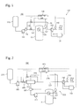
- FIG. 1 is a configuration diagram illustrating a cold heat recovery apparatus using an LNG fuel according to a first embodiment of the present invention.
- the cold heat recovery apparatus 100 using the LNG fuel may include an LNG fuel tank 110 configured to store an LNG as a fuel, and a pressure control unit 120 serving as cold heat usage means configured to control a pressure of a liquefied gas tank 10 by using a low-temperature characteristic, that is, cold heat of the LNG discharged from the LNG fuel tank 110.
- a liquefied gas tank 10 may store CO 2 or hydrocarbon liquefied gas such as an LPG, and other various liquefied gases as a cargo.
- the LNG fuel tank 110 is made of a container for withstanding a pressure and low-temperature of the LNG, and stores the LNG used as a fuel of a liquefied gas carrier.
- the pressure control unit 120 may include an LNG line 121 and a first pump 122.
- the LNG line 121 is installed to extend from the LNG fuel tank 110 and pass through the liquefied gas tank 10, such that heat exchange is performed between the LNG and the fluid stored in the liquefied gas tank 10.
- the first pump 122 is installed on the LNG line 121 to provide a pumping force for transferring the LNG through the LNG line 121.
- a coil portion 123 having a coil shape may be formed in a portion of the LNG line 121 which passes through the inside of the liquefied gas tank 10. Therefore, the coil portion 123 of the LNG line 121 increases a pipeline length or a pipeline area inside the liquefied gas tank 10, which can increase the efficiency of heat exchange with the fluid stored in the liquefied gas tank 10. In addition, a rise in the pressure of the liquefied gas tank 10 can be efficiently reduced.
- a temperature of the LNG within the LNG fuel tank 110 is about -163°C, and the temperature of the LNG slightly rises while the LNG passes through the first pump 122.
- the LNG is stored at about -163°C
- liquefied gas as a cargo for example, CO 2
- the LPG is stored at about -50°C. Therefore, the temperature of the LNG rises when the LNG passes through the liquefied gas tank 10, and then, the LNG has a condition suitable for an engine when the LNG passes through an evaporator 130 to be described below.
- the LNG line 121 may pass through a portion where gas is located within the liquefied gas tank 10. Therefore, a rise in the pressure of the liquefied gas tank 10 is suppressed by reliquefying gases close to the cold LNG line 121 within the liquefied gas tank 10.
- the LNG line 121 may pass through a liquid portion, that is, a portion where a liquid is located within the liquefied gas tank 10. Since a temperature of the liquefied gas within the liquefied gas tank 10 is lowered by the cold LNG line 121, a temperature of a free surface of the liquid is lowered, and thus, a saturation pressure on the free surface is lowered. Therefore, the pressure inside the liquefied gas tank 10 can be controlled.
- the pressure control unit 120 may further include a heater 124 installed in the front of the liquefied gas tank 10 in the LNG line 121.
- the heater 124 increases the temperature of the LNG supplied to the liquefied gas tank 10 to some degree, so as to prevent thermal deformation of the liquefied gas tank 10 caused when the temperature of the LNG is too low, or prevent the liquefied gas from condensing around the LNG line 121 and becoming frost.
- the pressure control unit 120 may further include a first bypass line 125 and a control valve 126.
- the first bypass line 125 is connected to the LNG line 121 to bypass the liquefied gas tank 10.
- the control valve 126 is installed in the LNG line 121 and the first bypass valve 125 to control the flow of the LNG through the liquefied gas tank 10 and the first bypass line 125. Therefore, the supercooling of the liquefied gas tank 10 is prevented by supplying the liquefied gas tank 10 with the LNG fuel such that only an amount of LNG fuel necessary for controlling the pressure of the liquefied gas tank 10 is used as a coolant.
- a pair of control valves 126 may be installed in the LNG line 121 and the first bypass line 125 one by one as in the present embodiment, but the present invention is not limited thereto. For example, a three-way valve may be used.
- the pressure control unit 120 may further include a pressure detection unit 127 and a control unit 128.
- the pressure detection unit 127 is installed in the liquefied gas tank 10 to measure the pressure inside the liquefied gas tank 10 and output a detection signal.
- the control unit 128 receives the detection signal output from the pressure detection unit 127 and controls the control valve 126.
- the control unit 128 measures the pressure inside the liquefied gas tank 10 through the pressure detection unit 127. When the measured pressure is increased to above a set pressure, the control unit 128 may control the control valve 126 such that the LNG passes through the liquefied gas tank 10. When the measured pressure is decreased to the set pressure, the control unit 128 may control the control valve 126 such that the LNG bypasses the liquefied gas tank 10.
- An evaporator 130 may be installed in the rear of the liquefied gas tank 10 in the LNG line 121. Therefore, the LNG has a condition suitable for an engine by evaporating the LNG having passed through the liquefied gas tank 10.
- the cold heat recovery apparatus 100 using the LNG fuel according to the first embodiment of the present invention may further include a temperature detection unit 140 and a control unit 128.
- the temperature detection unit 140 is installed in the rear of the evaporator 130 in the LNG line 121 to measure the temperature of the fluid having passed through the evaporator 130 and output a detection signal.
- the control unit 128 receives the detection signal output from the temperature detection unit 140 and controls a heat quantity of the evaporator 130.
- the control unit 128 increases the heat quantity of the evaporator 130.
- control unit 128 reduces the heat quantity of the evaporator 130.
- the control unit 128 can control the heat quantity of the evaporator 130 by controlling a heat supply unit 131 that supplies the evaporator 130 with heat by electricity or through the medium of liquid or gas.
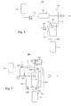
- FIG. 2 is a configuration diagram illustrating a cold heat recovery apparatus using an LNG fuel according to a second embodiment of the present invention.
- the cold heat recovery apparatus 200 using the LNG fuel according to the second embodiment of the present invention may include an LNG fuel tank 210 and a pressure control unit 220 serving as cold heat usage means.
- the following description will focus on differences from the cold heat recovery apparatus 100 using the LNG fuel according to the first embodiment of the present invention.
- the pressure control unit 220 may include an LNG line 221, a second pump 222, a heat exchanger 223, a coolant circulation line 224, and a coolant pump 225.
- the LNG line 221 is configured to transfer the LNG fuel from the LNG fuel tank 10.
- the second pump 222 is configured to provide a pumping force for transferring the LNG fuel through the LNG line 221.
- the heat exchanger 223 is installed in the LNG line 221.
- the coolant circulation line 224 is installed to pass through the liquefied gas tank 10 and configured to circulate the coolant and supply the coolant to the heat exchanger 223.
- the coolant pump 225 is configured to provide a pumping force for circulating the coolant through the coolant circulation line 224.
- the coolant is cooled by the heat exchange with the LNG passing through the LNG line 221, and the cooled coolant passes through the liquefied gas tank 10 by way of the coolant circulation line 224.
- the coolant circulation line 224 since cold heat is supplied to the liquefied gas tank 10, the liquefied gas inside the liquefied gas tank is cooled, and the pressure inside the liquefied gas tank 10 is controlled.
- the coolant has a freezing point (melting point) lower than the temperature of the LNG so as not to be condensed. Since the temperature of the coolant inside the closed loop, that is, the coolant circulation line 224, is higher than the temperature of the LNG, a thermal stress of the liquefied gas tank 10 can be reduced. In addition, it is possible to avoid a condensation problem in the vicinity of the pipeline due to the liquefied gas having a higher melting point than the LNG, for example, CO 2 or LPG.
- a coil portion 232 having a coil shape may be formed in a portion of the coolant circulation line 224 which is inserted into the liquefied gas tank 10.
- the pressure control unit 220 may include a make-up tank 226, a pressure detection unit 227, and a control unit 228.
- the make-up tank 226 supplies the coolant to the LNG line 221.
- the pressure detection unit 227 is installed in the liquefied gas tank 10 to measure the pressure inside the liquefied gas tank 10 and output a detection signal.
- the control unit 228 receives the detection signal output from the pressure detection unit 227 and controls the supply of the coolant from the make-up tank 226 to the LNG line 221.
- the control unit 228 can control an amount of coolant supplied from the make-up tank 226 to the LNG line 221 by a valve or a separate pump.
- the control unit 228 discharges the coolant from the make-up tank 226, so that a flow rate of the coolant is increased.
- a flow rate of the coolant is increased.
- the pressure control unit 220 may further include a pressure detection unit 227 and a control unit 228.
- the pressure detection unit 227 is installed in the liquefied gas tank 10 to measure the pressure inside the liquefied gas tank 10 and output a detection signal.
- the control unit 228 receives the detection signal output from the pressure detection unit 127 and controls a pumping force of the coolant pump 225 provided with a variable pump. Therefore, the control unit 228 can control a coolant flow speed of the closed loop such that the pressure inside the liquefied gas tank 10 measured by the pressure detection unit 227 has a set pressure.
- the pressure control unit 220 may further include a second bypass line 229, a control valve 230, a pressure detection unit 227, and a control unit 228.
- the second bypass line 229 is connected to the LNG line 221 to bypass the heat exchanger 223.
- the control valve 230 is installed in the LNG line 221 and the second bypass line 229 to control the flow of the LNG through the heat exchanger 223 and the second bypass line 229.
- the pressure detection unit 227 is installed in the liquefied gas tank 10 to measure the pressure inside the liquefied gas tank 10 and output a detection signal.
- the control unit 228 receives the detection signal output from the pressure detection unit 227 and controls the control valve 230.
- control unit 228 When the pressure inside the liquefied gas tank 10 measured by the pressure detection unit 227 is increased, the control unit needs to control the control valve 230 so as to remove a large heat quantity of the liquefied gas by the heat exchanger 223. Therefore, the control unit 228 reduces the flow rate of the LNG bypassing the heat exchanger 223 by the second bypass line 229. In the opposite case, the control unit 228 increases the flow rate of the LNG bypassing the heat exchanger 223.
- the control valve 230 may be provided with a pair of valves like the present embodiment, but the present invention is not limited thereto. For example, a single three-way valve may be used as the control valve 230.
- the cold heat recovery apparatus 200 using the LNG fuel according to the second embodiment of the present invention may include an evaporator 240, a heat supply unit 241, and a temperature detection unit 250.
- FIG. 3 is a configuration diagram illustrating a cold heat recovery apparatus using an LNG fuel according to a third embodiment of the present invention.
- the cold heat recovery apparatus 300 using the LNG fuel may include a fuel tank 310 and a reliquefaction tank 320 serving as cold heat usage means.
- the LNG fuel tank 310 is a tank for storing an LNG fuel of a liquefied gas carrier and is made of a container for withstanding a pressure and low-temperature of the LNG.
- the reliquefaction tank 320 reliquefies boil-off gas supplied from the liquefied gas tank 10 storing the liquefied gas through a gas pipeline 321 by using cold heat of the LNG discharged from the LNG fuel tank 310, and supplies the reliquefied boil-off gas through a liquid pipeline 322 to the liquefied gas tank 10.
- An LNG line 311 configured to transfer the LNG as the fuel discharged from the LNG fuel tank 310 is installed to pass through the reliquefaction tank 320.
- the reliquefaction tank 320 reliquefies the boil-off gas by the heat exchange with the LNG.
- the reliquefaction tank 320 may be installed at a position higher than the liquefied gas tank 10 such that reliquefied gas obtained by the heat exchange between the boil-off gas and the LNG is supplied through the liquid pipeline 322 to the liquefied gas tank 10 by gravity.
- the LNG line 311 provides a passage for supplying the LNG to the engine or the like.
- an LNG pump 311a is installed for pumping the LNG.
- a coil portion 311b may be provided for increasing a contact area in a portion of the LNG line 311 located within the reliquefaction tank 320.
- An evaporator 350 is installed to evaporate the LNG such that the LNG meets a condition as a fuel.
- the cold heat recovery apparatus 300 using the LNG fuel according to the third embodiment of the present invention may further include a gas manifold 330 and a liquid manifold 340.
- the gas manifold 330 is configured to supply the reliquefaction tank 320 with boil-off gas supplied from each of the liquefied gas tanks 10.
- the liquid manifold 340 is configured to distribute the reliquefied gas discharged from the reliquefaction tank 320 to each of the liquefied gas tanks 10.
- one reliquefaction tank 320 may be provided like the present embodiment, but the present invention is not limited thereto.
- a plurality of reliquefaction tanks 320 may be provided.
- gas manifolds 330 and liquid manifolds 340 may be installed in the respective reliquefaction tanks 320, or a gas manifold 330 and a liquid manifold 340 may be integrally installed with respect to all reliquefaction tanks 320.
- the gas manifold 330 and the liquid manifold 340 are installed in the gas pipeline 321 and the liquid pipeline 322, respectively.
- the gas pipeline 321 and the liquid pipeline 322 are branched into a plurality of pipelines such that the branched pipelines are connected to a plurality of liquefied gas tanks 10 on the basis of the gas manifold 330 and the liquid manifold 340.
- the cold heat recovery apparatus 300 using the LNG fuel when boil-off gas generated from the liquefied gas tank 10 usable as a cargo tank is supplied through the gas pipeline 321 to the reliquefaction tank 320, the boil-off gas is reliquefied by the heat exchange with the LNG of the LNG line 311 passing through the reliquefaction tank 320, and the reliquefied gas is resupplied to the liquefied gas tank 10 through the liquid pipeline 322.
- FIG. 4 is a configuration diagram illustrating a cold heat recovery apparatus using an LNG fuel according to a fourth embodiment of the present invention.
- the cold heat recovery apparatus 400 using the LNG fuel according to the fourth embodiment of the present invention includes an LNG fuel tank 410 and a reliquefaction tank 420 serving as cold heat usage means.
- the reliquefaction tank 420 is configured to reliquefy boil-off gas by the heat exchange with a coolant supplied by a coolant circulation unit 430 using the LNG discharged from the LNG fuel tank 410, instead of the direct heat exchange with the LNG discharged from the LNG fuel tank 410 in order for use as the fuel.
- the coolant circulation unit 430 may include a heat exchanger 431, a coolant circulation line 432, and a circulation pump 433.
- the heat exchanger 431 is installed in the LNG line 411 through which the LNG is discharged from the LNG fuel tank 410.
- the coolant circulation line 432 is installed to circulate and supply the coolant to the heat exchanger 431 and pass through the reliquefaction tank 420.
- the circulation pump 433 is configured to provide a pumping force for circulating the coolant through the coolant circulation line 432.
- a coil portion 432a may be provided for increasing a contact area in a portion of the coolant circulation line 432 which is inserted into the reliquefaction tank 420.
- the LNG discharged from the LNG fuel tank 410 through the LNG line 411 exchanges heat with the coolant circulated by the pumping force of the circulation pump 433 in the heat exchanger 431.
- the cooled coolant passes through the reliquefaction tank 420, and the boil-off gas supplied from the liquefied gas tank 10 through the gas pipeline 421 to the reliquefaction tank 421 is reliquefied by the heat exchange with the coolant and is resupplied through a liquid pipeline 422 to the liquefied gas tank 10.
- the coolant has a freezing point (melting point) lower than the temperature of the LNG so as not to be condensed. Since the temperature of the coolant inside the closed loop, that is, the coolant circulation line 224, is higher than the temperature of the LNG, a thermal stress of the liquefied gas tank 10 can be reduced. In addition, it is possible to avoid a condensation problem in the vicinity of the pipeline due to the liquefied gas having a higher freezing point than the LNG, for example, CO 2 or LPG.
- FIG. 5 is a configuration diagram illustrating a cold heat recovery apparatus using an LNG fuel according to a fifth embodiment of the present invention.
- the cold heat recovery apparatus 500 using the LNG fuel according to the fifth embodiment of the present invention includes an LNG fuel tank 510 and a reliquefaction tank 520 serving as cold heat usage means.
- An LNG line 511 configured to discharge the LNG from the LNG fuel tank 10 is installed to pass through the reliquefaction tank 520, so that boil-off gas is reliquefied by the heat exchange with the LNG.
- the cold heat recovery apparatus 500 using the LNG fuel according to the fifth embodiment of the present invention may further include a bypass line 531 and a control valve 532.
- the bypass line 531 is connected to the LNG line 511 to bypass the reliquefaction tank 520.
- the control valve 532 is installed in the LNG line 511 and the bypass line 531 to control the flow of the LNG through the reliquefaction tank 520 and the bypass line 531.
- a pair of control valves 532 may be installed in the bypass line 531 and the LNG line 511, respectively.
- the control valve 532 may be a single three-way valve installed in a connection portion of the bypass line 531 and the LNG line 511.
- the cold heat recovery apparatus 500 using the LNG fuel according to the fifth embodiment of the present invention may further include a detection unit 533 and a control unit 534.
- the detection unit 533 measures the temperature or pressure inside the reliquefaction tank 520 and outputs a detection signal.
- the control unit 534 receives the detection signal output from the detection unit 533 and controls the control valve 532.
- the reliquefaction tank 520 may be forcibly supplied with boil-off gas from the liquefied gas tank 10 by a compressor (not illustrated) installed in a gas pipeline 521, or may forcibly transfer the reliquefied gas to the liquefied gas tank 10 by a transfer pump (not illustrated) installed in a liquid pipeline 522.
- the cold heat recovery apparatus 500 using the LNG fuel according to the fifth embodiment of the present invention may further include a control valve 535, a pressure detection unit 536, and a control unit 534.
- the control valve 535 is installed in the gas pipeline 521.
- the pressure detection unit 536 measures the pressure inside the liquefied gas tank 10 and outputs a detection signal.
- the control unit 534 receives the detection signal of the pressure detection unit 536 and controls the control valve 535.
- the cold heat recovery apparatus 500 using the LNG fuel according to the fifth embodiment of the present invention may further include a control valve 537, a water level detection unit 538, and a control unit 534.
- the control valve 537 is installed in the liquid pipeline 522.
- the water level detection unit 538 measures a water level of the reliquefaction tank 520 and outputs a detection signal.
- the control unit 534 receives the detection signal of the water level detection unit 538 and controls the control valve 537.
- the cold heat recovery apparatus 500 using the LNG fuel according to the fifth embodiment of the present invention may further include a control valve 537, a pressure detection unit 536, and a control unit 534.
- the control valve 535 is installed in the gas pipeline 522.
- the pressure detection unit 536 measures the pressure inside the liquefied gas tank 10 and outputs a detection signal.
- the control unit 537 receives the detection signal of the pressure detection unit 536 and controls the control valve 535.
- the control unit 534 controls the control valve 532 such that the flow of the LNG via the LNG line 511 passing through the reliquefaction tank 520 is increased.
- the control unit 534 controls the control valve 532 such that the flow of the LNG via the LNG line 511 is reduced and the flow of the LNG passing through the bypass line 531 is increased.
- the reliquefaction tank 520 is configured to be smoothly supplied with boil-off gas from the liquefied gas tank 10 through the compressor, and to stably supply the reliquefied gas to the liquefied gas tank 10 by the transfer pump.
- the reliquefaction tank 520 is configured to increase the temperature by causing a heater to provide heat.
- the control unit 534 may reduce the pressure inside the liquefied gas tank 10 by opening the control valve 535.
- the control unit 534 may increase the pressure inside the liquefied gas tank 10 by closing the control valve 535.
- control unit 534 controls the control valve 537 such that the water level of the reliquefaction tank 520 measured by the water level detection unit 538 is maintained at a set water level.
- the control unit 534 reduces the pressure and temperature inside the liquefied gas tank 10 by opening the control valve 537 to cause the cold reliquefied gas to flow into the liquefied gas tank 10.
- FIG. 6 is a configuration diagram illustrating a cold heat recovery apparatus using an LNG fuel according to a sixth embodiment of the present invention.
- the cold heat recovery apparatus 600 using the LNG fuel according to the sixth embodiment of the present invention may include an LNG fuel tank 610 and a heat exchanger 620 serving as cold heat usage means.
- the cold heat recovery apparatus 600 using the LNG fuel according to the sixth embodiment differs from the cold heat recovery apparatus according to the third embodiment in that the heat exchanger 620 is used instead of the reliquefaction tank 320.
- the LNG fuel tank 610 is a tank that stores an LNG fuel of a liquefied gas carrier.
- the LNG fuel tank 610 is made of a container for withstanding a pressure and low-temperature of the LNG, and supplies the LNG as a fuel through the LNG line 611.
- the heat exchanger 620 is installed in the LNG line 611.
- An LNG pump 611a and an on/off valve 611b may be installed in the front of the heat exchanger 620.
- the LNG pump 611a is configured to provide a pumping force for transferring the LNG.
- the on/off valve 611b is provided with a control valve as an example of opening and closing the supply of the LNG.
- An evaporator 650 may be installed in the rear of the heat exchanger 620 to evaporate the LNG such that the LNG can be used suitably as a gaseous fuel.
- the heat exchanger 620 reliquefies boil-off gas supplied from the liquefied gas tank 10 storing the liquefied gas through a gas pipeline 621 by the heat exchange with the LNG discharged from the LNG fuel tank 610 by using a low-temperature characteristic of the LNG, and supplies the reliquefied boil-off gas through a liquid pipeline 622 to the liquefied gas tank 10.
- the heat exchanger 620 may be forcibly supplied with the boil-off gas from the liquefied gas tank 10 by a compressor 623 installed in a gas pipeline 621. Therefore, when the heat exchange occurs in the heat exchanger 620, the boil-off gas sublimates, and thus, the boil-off gas can be liquefied without being solidified.
- the cold heat recovery apparatus 600 using the LNG fuel according to the sixth embodiment of the present invention may further include a gas manifold 630 and a liquid manifold 640.
- the gas manifold 330 is configured to supply the heat exchanger 620 with boil-off gas supplied from each of the liquefied gas tanks 10.
- the liquid manifold 640 is configured to distribute the reliquefied gas discharged from the heat exchanger 620 to each of the liquefied gas tanks 10.
- one heat exchanger 620 may be provided like the present embodiment, but the present invention is not limited thereto.
- a plurality of heat exchangers 620 may be provided.
- gas manifolds 630 and liquid manifolds 640 may be installed in the respective heat exchangers 620, or a gas manifold 630 and a liquid manifold 640 may be integrally connected to all heat exchangers 620.
- the gas manifold 630 and the liquid manifold 640 are installed in the gas pipeline 621 and the liquid pipeline 622, respectively.
- the gas pipeline 621 and the liquid pipeline 622 are branched into a plurality of pipelines such that the branched pipelines are connected to liquefied gas tanks 10 on the basis of the gas manifold 630 and the liquid manifold 640.
- the cold heat recovery apparatus 600 using the LNG fuel when boil-off gas generated from the liquefied gas tank 10 usable as a cargo tank is supplied through the gas pipeline 321 to the heat exchanger 620 by the compressor 623, the boil-off gas is reliquefied by the heat exchange with the LNG of the LNG line 611 passing through the heat exchanger 620, and the reliquefied gas is resupplied to the liquefied gas tank 10 through the liquid pipeline 622
- the heat exchanger 620 is forcibly supplied with the boil-off gas by the compressor 623. Therefore, when the heat exchange occurs in the heat exchanger 620, the boil-off gas sublimates, and thus, the boil-off gas can be liquefied without being solidified.
- FIG. 7 is a configuration diagram illustrating a cold heat recovery apparatus using an LNG fuel according to a seventh embodiment of the present invention.
- the cold heat recovery apparatus 700 using the LNG fuel according to the seventh embodiment of the present invention includes an LNG fuel tank 710 and a heat exchanger 720 serving as cold heat usage means.
- the heat exchanger 720 reliquefies boil-off gas supplied from the liquefied gas tank 10 through a gas pipeline 721 by the heat exchange with the LNG discharged from the LNG fuel tank 710 storing an LNG fuel of a liquefied gas carrier through an LNG line 711 by a pumping of an LNG pump 711a, and supplies the reliquefied boil-off gas through a liquid pipeline 722 to the liquefied gas tank 10.
- the heat exchanger 720 may be forcibly supplied with the boil-off gas from the liquefied gas tank 10 by a compressor 723 installed in the gas pipeline 721. Like the sixth embodiment, the heat exchanger 720 can be supplied with the boil-off gas from a plurality of liquefied gas tanks 19 by a gas manifold and a liquid manifold, and can be distributed and supplied to the plurality of liquefied gas tanks 10 after reliquefying the boil-off gas.
- the cold heat recovery apparatus 700 using the LNG fuel according to the seventh embodiment of the present invention may further include a bypass line 731 and control valves 732 and 733.
- the bypass line 731 is connected to the LNG line 711 to bypass the heat exchanger 720.
- the control valves 732 and 733 are installed in the LNG line 711 and the bypass line 731 to control the flow of the LNG through the heat exchanger 720 and the bypass line 731.
- a pair of control valves 732 and 733 may be installed in the bypass line 731 and the LNG line 711, respectively.
- the control valves 732 and 733 may be a single three-way valve installed in a connection portion of the bypass line 731 and the LNG line 711.
- the cold heat recovery apparatus 700 using the LNG fuel according to the seventh embodiment of the present invention may further include a detection unit 734 and a control unit 735.
- the detection unit 734 measures the temperature or pressure inside the heat exchanger 720 and outputs a detection signal.
- the control unit 735 receives the detection signal output from the detection unit 734 and controls the control valves 732 and 733.
- the detection unit 734 may be a temperature sensor configured to measure the temperature inside the heat exchanger 720, or a pressure sensor configured to measure the pressure inside the heat exchanger 720.
- the control unit 735 controls the control valves 732 and 733 such that the flow rate of the LNG passing through the heat exchanger 720 is more increased than that passing through the bypass line 731.
- the control unit 735 controls the control valves 732 and 733 such that the flow rate of the LNG passing through the bypass line 731 is increased.
- a heater 740 may be installed inside (or outside) the heat exchanger 720 to provide heat.
- a temperature detection unit 739 may be installed in the liquid pipeline 722 to measure the temperature of the reliquefied gas and output a detection signal.
- the control unit 735 receives the detection signal of the temperature detection unit 739 and controls the heater 740. For example, when the temperature of the reliquefied liquefied gas within the liquid pipeline 722 detected by the temperature detection unit 739 falls to below a preset temperature, the control unit 735 operates the heater 740 to heat the heat exchanger 720 to thereby increase the temperature of the reliquefied liquefied gas.
- the heater 740 may be installed inside or outside the heat exchanger 720.
- the heater 740 may be provided with a hot wire or a heating block configured to convert electric energy into thermal energy, or may be provided with a heating pipe configured to circulate and supply a heating medium such as steam or hot water.
- the cold heat recovery apparatus 700 using the LNG fuel according to the seventh embodiment of the present invention may further include a control valve 736, a pressure detection unit 737, and a control unit 735.
- the control valve 736 is installed in the gas pipeline 721.
- the pressure detection unit 735 measures the pressure inside the liquefied gas tank 10 and outputs a detection signal.
- the control unit 735 receives the detection signal of the pressure detection unit 737 and controls the control valve 536. Therefore, when the pressure of the liquefied gas tank 10 detected by the pressure detection unit 737 becomes higher than the preset pressure, the control unit 735 opens the control valve 736 to supply the boil-off gas to the heat exchanger 720 so that the pressure inside the liquefied gas tank 10 is reduced.
- a control valve 738 configured to perform an operation corresponding to the control valve 736 installed in the gas pipeline may be installed in the liquid pipeline 722.
- the control unit 735 controls the control valves 722 and 723 such that the flow of the LNG via the LNG line 711 passing through the heat exchanger 720 is increased.
- the control unit 735 controls the control valves 722 and 723 such that the flow of the LNG via the LNG line 711 is reduced and the flow of the LNG passing through the bypass line 731 is increased.
- the control unit 735 When the temperature of the reliquefied liquefied gas within the liquid pipeline 722 detected by the temperature detection unit 739 falls to below the preset temperature, the control unit 735 operates the heater 740 to heat the heat exchanger 720 to thereby increase the temperature of the reliquefied liquefied gas.
- the control unit 735 may reduce the pressure inside the liquefied gas tank 10 by opening the control valve 736.
- the control unit 735 may increase the pressure inside the liquefied gas tank 10 by closing the control valve 536.
- the liquefied gas carrier using the LNG as the fuel according to the present invention may include the cold heat recovery apparatus using the LNG fuel according to the first to seventh embodiments of the present invention, and may include a storage tank capable of storing liquefied gas such as LPG or CO 2 as a cargo, and a fuel tank capable of storing the LNG as a fuel.
Landscapes
- Engineering & Computer Science (AREA)
- Mechanical Engineering (AREA)
- Chemical & Material Sciences (AREA)
- General Engineering & Computer Science (AREA)
- Physics & Mathematics (AREA)
- Thermal Sciences (AREA)
- Combustion & Propulsion (AREA)
- Chemical Kinetics & Catalysis (AREA)
- General Chemical & Material Sciences (AREA)
- Oil, Petroleum & Natural Gas (AREA)
- Ocean & Marine Engineering (AREA)
- Filling Or Discharging Of Gas Storage Vessels (AREA)
Applications Claiming Priority (4)
| Application Number | Priority Date | Filing Date | Title |
|---|---|---|---|
| KR1020110052274A KR101319364B1 (ko) | 2011-05-31 | 2011-05-31 | 연료용 lng를 이용한 액화가스탱크 압력 조절장치 및 이를 가지는 액화가스운반선 |
| KR1020110055067A KR101408357B1 (ko) | 2011-06-08 | 2011-06-08 | Lng를 이용한 액화가스 재액화장치 및 이를 가지는 액화가스운반선 |
| KR1020110076125A KR101335610B1 (ko) | 2011-07-29 | 2011-07-29 | Lng 연료를 이용한 액화가스 재액화장치 및 이를 가지는 액화가스운반선 |
| PCT/KR2012/004279 WO2012165865A2 (fr) | 2011-05-31 | 2012-05-31 | Appareil de récupération de chaleur et de froid utilisant un combustible de gaz naturel liquéfié et transporteur de gaz liquéfié incluant celui-ci |
Publications (2)
| Publication Number | Publication Date |
|---|---|
| EP2716542A2 true EP2716542A2 (fr) | 2014-04-09 |
| EP2716542A4 EP2716542A4 (fr) | 2016-05-04 |
Family
ID=47260081
Family Applications (1)
| Application Number | Title | Priority Date | Filing Date |
|---|---|---|---|
| EP12793505.4A Withdrawn EP2716542A4 (fr) | 2011-05-31 | 2012-05-31 | Appareil de récupération de chaleur et de froid utilisant un combustible de gaz naturel liquéfié et transporteur de gaz liquéfié incluant celui-ci |
Country Status (5)
| Country | Link |
|---|---|
| US (1) | US20140196474A1 (fr) |
| EP (1) | EP2716542A4 (fr) |
| JP (1) | JP6273472B2 (fr) |
| CN (1) | CN103619705A (fr) |
| WO (1) | WO2012165865A2 (fr) |
Cited By (3)
| Publication number | Priority date | Publication date | Assignee | Title |
|---|---|---|---|---|
| EP3444520A1 (fr) * | 2017-08-18 | 2019-02-20 | ArianeGroup GmbH | Refroidissement d'une évaporation de gaz liquéfié destiné à l'entraînement des machines, des installations ou des véhicules |
| FR3077867A1 (fr) * | 2018-02-09 | 2019-08-16 | Gaztransport Et Technigaz | Procede et systeme de traitement de gaz d'une installation de stockage de gaz pour un navire de transport de gaz |
| WO2020154621A1 (fr) * | 2019-01-25 | 2020-07-30 | Saudi Arabian Oil Company | Processus et procédé de transport d'hydrocarbure liquide et de co2 pour la production d'hydrogène avec capture de co2 |
Families Citing this family (25)
| Publication number | Priority date | Publication date | Assignee | Title |
|---|---|---|---|---|
| US9752727B2 (en) * | 2012-11-30 | 2017-09-05 | Chart Inc. | Heat management system and method for cryogenic liquid dispensing systems |
| KR101726668B1 (ko) * | 2014-02-24 | 2017-04-13 | 대우조선해양 주식회사 | 증발가스 처리 시스템 및 방법 |
| KR20150131860A (ko) * | 2014-05-16 | 2015-11-25 | 대우조선해양 주식회사 | Lpg 운반선의 연료공급 시스템 및 연료공급 방법 |
| CN104615168B (zh) * | 2014-12-03 | 2017-04-05 | 金川集团股份有限公司 | 液氯气化装置压力自动控制系统 |
| JP6541059B2 (ja) * | 2015-04-10 | 2019-07-10 | 三井E&S造船株式会社 | 液化ガス運搬船用燃料ガス供給システム |
| KR101848139B1 (ko) * | 2015-06-09 | 2018-04-11 | 현대중공업 주식회사 | 가스 처리 시스템을 포함하는 선박 |
| JP6609176B2 (ja) * | 2015-11-06 | 2019-11-20 | 川崎重工業株式会社 | 船舶 |
| WO2017078154A1 (fr) * | 2015-11-06 | 2017-05-11 | 川崎重工業株式会社 | Navire |
| CN109563967B (zh) * | 2016-05-11 | 2021-04-02 | 创新低温系统公司 | 气体储存及处理设备 |
| KR101876974B1 (ko) * | 2016-09-29 | 2018-07-10 | 대우조선해양 주식회사 | 선박용 증발가스 재액화 장치 및 방법 |
| US20180135805A1 (en) * | 2016-11-14 | 2018-05-17 | Priserve Consulting Inc | Open loop vaporization system and a method thereof |
| JP6347003B1 (ja) * | 2017-01-25 | 2018-06-20 | デウ シップビルディング アンド マリン エンジニアリング カンパニー リミテッド | Lng船の蒸発ガス再液化方法及びシステム |
| JP6941448B2 (ja) * | 2017-02-09 | 2021-09-29 | 三菱重工業株式会社 | 液化ガス運搬用液化ガス燃料船 |
| JP6565022B2 (ja) * | 2017-02-17 | 2019-08-28 | 三井E&S造船株式会社 | 液化ガス燃料船の交通経路形成構造 |
| CN110462278B (zh) * | 2017-03-08 | 2021-05-07 | 瓦锡兰芬兰有限公司 | 液化气罐装置和操作液化气罐装置的方法 |
| US11702183B2 (en) | 2017-09-11 | 2023-07-18 | Arcosa Marine Products, Inc. | Ice battery vessel and cold energy storage |
| CN107883181A (zh) * | 2017-09-29 | 2018-04-06 | 深圳市燃气集团股份有限公司 | 一种混合式液化天然气的bog液化再回收方法 |
| KR102404713B1 (ko) * | 2018-09-06 | 2022-06-08 | 카와사키 주코교 카부시키 카이샤 | 선박 |
| KR102336892B1 (ko) * | 2020-03-31 | 2021-12-10 | 주식회사 패리티 | 수소 재액화시스템 |
| KR102336884B1 (ko) * | 2020-04-03 | 2021-12-09 | 주식회사 패리티 | 수소 액화 및 자연기화가스 억제 시스템 |
| JP7022245B1 (ja) | 2021-08-05 | 2022-02-17 | 株式会社神戸製鋼所 | 圧縮機ユニット及び圧縮機ユニットの制御方法 |
| KR102632395B1 (ko) * | 2021-10-29 | 2024-02-01 | 한화오션 주식회사 | 선박용 재액화 시스템의 미세누수 감지 시스템 |
| CN115402473B (zh) * | 2022-09-29 | 2025-05-27 | 广东海洋大学 | 一种液货船运输液氢和lng的组合货舱及方法 |
| CN115823482B (zh) * | 2023-02-15 | 2023-05-12 | 济南华信流体控制有限公司 | 一种气体充装的管道系统 |
| WO2024182141A1 (fr) * | 2023-02-27 | 2024-09-06 | Choi Peter B | Récupération d'énergie froide de gnl à l'aide d'un coulis de glace |
Family Cites Families (21)
| Publication number | Priority date | Publication date | Assignee | Title |
|---|---|---|---|---|
| US2795937A (en) * | 1955-03-31 | 1957-06-18 | Phillips Petroleum Co | Process and apparatus for storage or transportation of volatile liquids |
| JPS62147197A (ja) * | 1985-12-18 | 1987-07-01 | Osaka Gas Co Ltd | 液化天然ガス貯槽のボイルオフガス再液化システム |
| US4995234A (en) * | 1989-10-02 | 1991-02-26 | Chicago Bridge & Iron Technical Services Company | Power generation from LNG |
| JPH06185698A (ja) * | 1992-12-15 | 1994-07-08 | Tokyo Gas Co Ltd | 液化ガス貯蔵タンク内に発生するbogの抑制装置 |
| JPH07119897A (ja) * | 1993-10-25 | 1995-05-12 | Tokyo Gas Co Ltd | Lpg貯蔵タンク内に発生するbogの抑制方法及びそ の装置 |
| JPH0918389A (ja) * | 1995-06-30 | 1997-01-17 | Takayoshi Hirata | 非調和的周波数分析法を用いた拡声通話系の ハウリング防止方式 |
| JP3821506B2 (ja) * | 1995-12-28 | 2006-09-13 | 大陽日酸株式会社 | 液化天然ガス貯槽の蒸発ガス再液化装置 |
| JPH10252996A (ja) * | 1997-03-11 | 1998-09-22 | Toshio Takeda | 発電所用lngの管理方法及び装置 |
| JP2004069215A (ja) * | 2002-08-08 | 2004-03-04 | Nippon Sanso Corp | 熱交換装置及びその制御方法並びに液化天然ガスの冷熱を利用した炭酸ガスの液化方法 |
| US7299643B2 (en) * | 2004-09-29 | 2007-11-27 | Chevron U.S.A. Inc. | Method for recovering LPG boil off gas using LNG as a heat transfer medium |
| CA2523732C (fr) * | 2005-11-10 | 2007-09-18 | Westport Research Inc. | Systeme et methode de livraison d'un gaz comprime a partir d'un recipient de stockage cryogenique |
| FI121745B (fi) * | 2005-12-28 | 2011-03-31 | Waertsilae Finland Oy | Järjestely ja menetelmä jäähdytysenergian tuottamiseksi vesialuksen jäähdytysväliainepiiriin |
| US20080276627A1 (en) * | 2007-05-08 | 2008-11-13 | Daewoo Shipbuilding & Marine Engineering Co., Ltd. | Fuel gas supply system and method of a ship |
| KR101076266B1 (ko) * | 2007-07-19 | 2011-10-26 | 대우조선해양 주식회사 | Lng 운반선의 연료용 가스 공급 장치 |
| JP5148319B2 (ja) * | 2008-02-27 | 2013-02-20 | 三菱重工業株式会社 | 液化ガス再液化装置、これを備えた液化ガス貯蔵設備および液化ガス運搬船、並びに液化ガス再液化方法 |
| US8973398B2 (en) * | 2008-02-27 | 2015-03-10 | Kellogg Brown & Root Llc | Apparatus and method for regasification of liquefied natural gas |
| NO332551B1 (no) * | 2009-06-30 | 2012-10-22 | Hamworthy Gas Systems As | Fremgangsmate og anordning for lagring og transport av flytendegjort petroleumsgass |
| KR20110007450A (ko) * | 2009-07-16 | 2011-01-24 | 대우조선해양 주식회사 | 이산화탄소 수송용 선박 |
| JP2011033051A (ja) * | 2009-07-29 | 2011-02-17 | Shimizu Corp | 低温液化ガスの貯蔵施設 |
| DE102010020476B4 (de) * | 2010-05-14 | 2023-05-04 | Air Liquide Deutschland Gmbh | Verwendung einer Vorrichtung zum Speichern, Umfüllen und/oder Transportieren von tiefkalt verflüssigtem brennbarem Gas in einem Fahrzeug |
| JP2011245995A (ja) * | 2010-05-27 | 2011-12-08 | Ihi Corp | 液化ガス輸送船 |
-
2012
- 2012-05-31 CN CN201280026556.7A patent/CN103619705A/zh active Pending
- 2012-05-31 US US14/123,474 patent/US20140196474A1/en not_active Abandoned
- 2012-05-31 WO PCT/KR2012/004279 patent/WO2012165865A2/fr not_active Ceased
- 2012-05-31 EP EP12793505.4A patent/EP2716542A4/fr not_active Withdrawn
- 2012-05-31 JP JP2014513437A patent/JP6273472B2/ja active Active
Cited By (6)
| Publication number | Priority date | Publication date | Assignee | Title |
|---|---|---|---|---|
| EP3444520A1 (fr) * | 2017-08-18 | 2019-02-20 | ArianeGroup GmbH | Refroidissement d'une évaporation de gaz liquéfié destiné à l'entraînement des machines, des installations ou des véhicules |
| DE102017118951B4 (de) * | 2017-08-18 | 2019-11-14 | Arianegroup Gmbh | Kühlung einer Abdampfung von Flüssiggas zum Antrieb von Maschinen, Anlagen oder Fahrzeugen |
| US10850825B2 (en) | 2017-08-18 | 2020-12-01 | Arianegroup Gmbh | Cooling of a vaporized content of a liquefied gas for the purpose of powering machinery, plants or vehicles |
| FR3077867A1 (fr) * | 2018-02-09 | 2019-08-16 | Gaztransport Et Technigaz | Procede et systeme de traitement de gaz d'une installation de stockage de gaz pour un navire de transport de gaz |
| WO2020154621A1 (fr) * | 2019-01-25 | 2020-07-30 | Saudi Arabian Oil Company | Processus et procédé de transport d'hydrocarbure liquide et de co2 pour la production d'hydrogène avec capture de co2 |
| US11125391B2 (en) | 2019-01-25 | 2021-09-21 | Saudi Arabian Oil Company | Process and method for transporting liquid hydrocarbon and CO2 for producing hydrogen with CO2 capture |
Also Published As
| Publication number | Publication date |
|---|---|
| WO2012165865A2 (fr) | 2012-12-06 |
| EP2716542A4 (fr) | 2016-05-04 |
| US20140196474A1 (en) | 2014-07-17 |
| CN103619705A (zh) | 2014-03-05 |
| JP6273472B2 (ja) | 2018-02-07 |
| JP2014517230A (ja) | 2014-07-17 |
| WO2012165865A3 (fr) | 2013-03-28 |
Similar Documents
| Publication | Publication Date | Title |
|---|---|---|
| EP2716542A2 (fr) | Appareil de récupération de chaleur et de froid utilisant un combustible de gaz naturel liquéfié et transporteur de gaz liquéfié incluant celui-ci | |
| KR101291947B1 (ko) | 해양선박의 냉매 순환로에의 냉각 에너지 공급장치 및 방법 | |
| US9726327B2 (en) | System and method for processing liquefied gas | |
| KR101319364B1 (ko) | 연료용 lng를 이용한 액화가스탱크 압력 조절장치 및 이를 가지는 액화가스운반선 | |
| KR101686505B1 (ko) | 선박의 엔진 냉각수의 폐열을 이용한 연료가스 공급시스템 및 방법 | |
| KR101195153B1 (ko) | 부유식 구조물 | |
| AU2005257930A1 (en) | Apparatus and methods for converting a cryogenic fluid into gas | |
| KR20130084908A (ko) | 천연가스 연료공급 시스템 및 천연가스 연료공급 시스템이 탑재된 선박 | |
| KR101408357B1 (ko) | Lng를 이용한 액화가스 재액화장치 및 이를 가지는 액화가스운반선 | |
| KR101903767B1 (ko) | 액화가스 재기화 시스템 | |
| KR20190041859A (ko) | Lng연료를 이용한 액화가스 재액화장치 및 이를 가지는 액화가스운반선 | |
| KR102521169B1 (ko) | 부유식 발전플랜트의 lng 재기화열을 이용한 육상 hvac 냉매 순환 시스템 | |
| KR20230166112A (ko) | 선박의 가스 소비 장치용 가스 공급 시스템의 열교환기를 냉각하는 방법 | |
| KR200410836Y1 (ko) | 액화천연가스선의 액화천연가스 재기화시스템 | |
| KR101903760B1 (ko) | 액화가스 재기화 시스템 | |
| CN213873320U (zh) | 一种船载lng冷能利用系统 | |
| KR100896927B1 (ko) | 액화가스 운반선의 증발가스 억제장치 및 억제방법, 그리고상기 억제장치를 구비한 액화가스 운반선 | |
| KR101647465B1 (ko) | 선박 또는 해상구조물의 일체형 냉각 및 기화 시스템 | |
| KR101903761B1 (ko) | 액화가스 재기화 시스템 | |
| KR20210090842A (ko) | 에너지 절약형 연료가스 가열 시스템 및 방법 | |
| KR102352166B1 (ko) | 액화가스 재기화 시스템 및 이를 포함하는 선박 | |
| KR102821189B1 (ko) | 선박의 소기 냉각 시스템 및 방법 | |
| Madsen et al. | Intermediate fluid vaporizers for LNG regasification vessels (SRVs) and FSRUs | |
| KR20130084535A (ko) | 천연가스 연료공급 시스템 | |
| KR101916694B1 (ko) | 액화가스 재기화 시스템 |
Legal Events
| Date | Code | Title | Description |
|---|---|---|---|
| PUAI | Public reference made under article 153(3) epc to a published international application that has entered the european phase |
Free format text: ORIGINAL CODE: 0009012 |
|
| 17P | Request for examination filed |
Effective date: 20131129 |
|
| AK | Designated contracting states |
Kind code of ref document: A2 Designated state(s): AL AT BE BG CH CY CZ DE DK EE ES FI FR GB GR HR HU IE IS IT LI LT LU LV MC MK MT NL NO PL PT RO RS SE SI SK SM TR |
|
| DAX | Request for extension of the european patent (deleted) | ||
| RIC1 | Information provided on ipc code assigned before grant |
Ipc: F25J 1/00 20060101ALI20151209BHEP Ipc: F02D 19/02 20060101ALI20151209BHEP Ipc: B63B 25/16 20060101ALI20151209BHEP Ipc: F02M 21/02 20060101ALI20151209BHEP Ipc: F17C 9/04 20060101ALI20151209BHEP Ipc: B63H 21/38 20060101ALI20151209BHEP Ipc: B63J 2/14 20060101AFI20151209BHEP Ipc: B63J 99/00 20090101ALI20151209BHEP Ipc: F25J 1/02 20060101ALI20151209BHEP |
|
| A4 | Supplementary search report drawn up and despatched |
Effective date: 20160405 |
|
| RIC1 | Information provided on ipc code assigned before grant |
Ipc: F02D 19/02 20060101ALI20160330BHEP Ipc: B63J 99/00 20090101ALI20160330BHEP Ipc: B63J 2/14 20060101AFI20160330BHEP Ipc: B63H 21/38 20060101ALI20160330BHEP Ipc: B63B 25/16 20060101ALI20160330BHEP Ipc: F17C 9/04 20060101ALI20160330BHEP Ipc: F25J 1/00 20060101ALI20160330BHEP Ipc: F25J 1/02 20060101ALI20160330BHEP Ipc: F02M 21/02 20060101ALI20160330BHEP |
|
| 17Q | First examination report despatched |
Effective date: 20180823 |
|
| STAA | Information on the status of an ep patent application or granted ep patent |
Free format text: STATUS: THE APPLICATION IS DEEMED TO BE WITHDRAWN |
|
| 18D | Application deemed to be withdrawn |
Effective date: 20190103 |