EP2716558A1 - Dispositif de fixation d'étiquettes en forme de film - Google Patents
Dispositif de fixation d'étiquettes en forme de film Download PDFInfo
- Publication number
- EP2716558A1 EP2716558A1 EP12792298.7A EP12792298A EP2716558A1 EP 2716558 A1 EP2716558 A1 EP 2716558A1 EP 12792298 A EP12792298 A EP 12792298A EP 2716558 A1 EP2716558 A1 EP 2716558A1
- Authority
- EP
- European Patent Office
- Prior art keywords
- label
- film
- container
- containers
- picker
- Prior art date
- Legal status (The legal status is an assumption and is not a legal conclusion. Google has not performed a legal analysis and makes no representation as to the accuracy of the status listed.)
- Granted
Links
- 230000007246 mechanism Effects 0.000 claims description 39
- 238000003848 UV Light-Curing Methods 0.000 description 14
- 230000009471 action Effects 0.000 description 14
- 239000000853 adhesive Substances 0.000 description 14
- 230000001070 adhesive effect Effects 0.000 description 14
- 238000007599 discharging Methods 0.000 description 12
- 238000000034 method Methods 0.000 description 5
- 230000008569 process Effects 0.000 description 5
- 230000008859 change Effects 0.000 description 3
- 230000001678 irradiating effect Effects 0.000 description 3
- 238000010586 diagram Methods 0.000 description 2
- 230000000694 effects Effects 0.000 description 2
- 238000007493 shaping process Methods 0.000 description 2
- 238000011144 upstream manufacturing Methods 0.000 description 2
- XLYOFNOQVPJJNP-UHFFFAOYSA-N water Substances O XLYOFNOQVPJJNP-UHFFFAOYSA-N 0.000 description 2
- 239000004831 Hot glue Substances 0.000 description 1
- 230000005540 biological transmission Effects 0.000 description 1
- 238000010438 heat treatment Methods 0.000 description 1
- 239000007921 spray Substances 0.000 description 1
Images


Classifications
-
- B—PERFORMING OPERATIONS; TRANSPORTING
- B65—CONVEYING; PACKING; STORING; HANDLING THIN OR FILAMENTARY MATERIAL
- B65C—LABELLING OR TAGGING MACHINES, APPARATUS, OR PROCESSES
- B65C3/00—Labelling other than flat surfaces
- B65C3/06—Affixing labels to short rigid containers
- B65C3/065—Affixing labels to short rigid containers by placing tubular labels around the container
Definitions
- the present invention relates to a film label fitting apparatus.
- a film label fitting apparatus configured to shape a film label into a cylindrical shape before fitting the film label around the barrel of a container.
- Film label fitting apparatuses configured to fit a film label in a cylindrical shape around the barrel of a container are well known (see Patent Documents 1 and 2, for example).
- the apparatus according to Patent Document 1 is configured to cut a film label in a band shape to a predetermined length, shaping the resulting film label into a cylindrical shape by wrapping the film label around a mandrel and fusing the opposite ends with each other, and then holding the film label in the cylindrical shape with a picker and lowering the film label to fit the film label around the outer periphery of a container.
- the apparatus according to Patent Document 1 is configured so that two, upper and lower, contact parts 36 of a pick-up device 33 hold a label 11 in the cylindrical shape at only two points vertically spaced apart from each other.
- the apparatus according to Patent Document 2 can fit film labels in a cylindrical shape having different outer diameters (spread widths) around containers having different outer diameters.
- the apparatus according to Patent Document 1 has a problem that the pick-up device 33 holds the film label 11 in the cylindrical shape with low stability, since the pick-up device 33 is configured to hold the film label 11 in the cylindrical shape at only two points vertically spaced apart from each other.
- the pick-up device 33 needs to be replaced with another pick-up device 33 suitable for the length.
- film labels in the cylindrical shape having different outer diameters can be fitted around containers.
- handling of film labels having different vertical dimensions is not taken into consideration.
- the present invention provides a film label fitting apparatus comprising: a rotator that is rotatably provided; a plurality of mounts provided on the rotator on which containers are mounted; supporting members that are provided above the respective mounts so as to be capable of being raised and lowered with respect to the mounts and support mouths of the containers to hold the containers between the supporting members and the mounts; mandrels that are provided for the respective mounts on the rotator to hold and shape film labels into a cylindrical shape; pickers that are disposed on the respective mandrels and hold, from outside, the film labels shaped into the cylindrical shape by the mandrels; and raising and lowering mechanisms that raise and lower the pickers between the level of the mandrels and the level of the containers on the mounts when the rotator rotates, the containers mounted on the mounts being conveyed as the rotator rotates, and the film labels shaped into the cylindrical shape by the mandrels being held by the pickers and fitted around barrels
- the adjustment mechanism can change the level at which fitting of the film labels by the pickers occur, so that the film labels having different vertical dimension can be fitted around the containers.
- the present invention can provide a highly versatile film label fitting apparatus.
- a film label fitting apparatus 1 is configured to cut a roll-fed film label 2 to a predetermined length, shape the cut film label 2 into a cylindrical shape and fit the film label 2 in the cylindrical shape around a barrel 3A of a container 3 having a circular cross section.
- the film label 2 is referred to also as a shrink label and is placed around the barrel 3A of the container 3, which is a plastic bottle, and then is heated to shrink and be tightly fitted on the outer periphery of the barrel 3A.
- the film label fitting apparatus 1 comprises a labeler main unit 5 that rotates clockwise to convey containers 3 supported on respective mounts 4 and fits a film label 2 in a cylindrical shape around the barrel 3A of each container 3, a feeding star wheel 11 that feeds the containers 3 onto the respective mounts 4 in the labeler main unit 5 at a feed position A, label feeding means 12 that cuts the roll-fed film label 2 to a predetermined length and feeds the cut film label 2 to the labeler main unit 5, and a discharging star wheel 13 that discharges the containers 3 off the respective mounts 4 at a discharge position B.
- the film label fitting apparatus 1 performs a process that begins with shaping the film label 2 cut to a predetermined length into a cylindrical shape and ends with fitting the film label 2 around the barrel 3A of the container 3 placed below the film label 2.
- the container 3 discharged off the mount 4 in the labeler main unit 5 by the discharging star wheel 13 is then conveyed to a subsequent process (not shown), in which the film label 2 in the cylindrical shape fitted around the barrel 3A of the container 3 is heated to shrink and be tightly fitted on the outer periphery of the barrel 3A.
- the film label fitting apparatus 1 is characterized by the capability of switching between fitting the film label 2 having a longer vertical dimension (a full label FL) around substantially the whole of the barrel 3A of the container 3 and fitting the film label 2 having a shorter vertical dimension (a half label HL) around only an upper part of the barrel 3A of the container 3 (see Figures 3(a) and 3(b) ).
- a feeding conveyer 14 that conveys a row of containers 3 in the standing position is disposed, and a timing screw 15 that spaces each container 3 on the feeding conveyer 14 away from the preceding and following containers 3 is provided.
- a discharging conveyer 16 that receives the containers 3 from the discharging star wheel 13 and conveys the containers 3 to a subsequent process on the downstream side is provided.
- the feeding star wheel 11 and the discharging star wheel 13 are each provided, on the outer periphery thereof, with a plurality of pockets that house and hold the containers 3.
- the feeding star wheel 11 is configured to successively feed the containers 3 spaced apart from each other by the timing screw 15 from the feeding conveyer 14 onto the mounts 4 at the feed position A.
- the discharging star wheel 13 is configured to discharge the containers 3 with the film label 2 fitted around the barrel 3A thereof off the mounts 4 and pass the containers 3 to the discharging conveyer 16 at the discharge position B.
- the labeler main unit 5 is configured to rotate clockwise in Figure 1 and convey the containers 3 on the respective mounts 4 from the feed position A to the discharge position B, and the label feeding means 12 is disposed at a position outside of a label feed position C in the conveyance path of the containers 3.
- the label feeding means 12 comprises a feed roller 21 that unrolls a length of film label 2 and feeds the film label 2, a rotary cutter 22 that successively cuts the roll-fed film label 2 to a predetermined length, and a feeding drum 24 that passes the film labels 2 having the predetermined length to respective mandrel 23 in the labeler main unit 5 at the label feed position C.
- the feed roller 21, the rotary cutter 22 and the feeding drum 24 are configured to rotate in synchronization with each other.
- the label feeding means 12 further comprises an applying roller 25 that applies an UV curing adhesive to each film label 2 having the predetermined length cut by the rotary cutter 22.
- the applying roller 25 is disposed adjacent to the outer periphery of the feeding drum 24.
- the applying roller 25 can be moved by a drive mechanism (not shown) between an advanced position and a retracted position. The applying roller 25 is in the advanced position when in operation and in the retracted position when not in operation.
- a large number of suction holes 24A is formed in the outer surface of the feeding drum 24, and a suction is exerted on all the suction holes 24A through a negative pressure channel inside of the feeding drum 24.
- the film labels 2 cut to the predetermined length by the rotary cutter 22 are sucked and held to the outer surface of the rotating feeding drum 24.
- each film label 2 is sucked and held to the outer surface of the feeding drum 24 in a reverse state, in which the back surface of the film label 2 faces up.
- the applying roller 25 is advanced at a predetermined time to apply the UV curing adhesive to the film label 2 sucked and held to the feeding drum 24.
- This process is designed so that the UV curing adhesive is applied to a rear end of each film label 2 held on the outer surface of the feeding drum 24.
- both the film label 2 having a longer vertical dimension (full label FL) and the film label 2 having a shorter vertical dimension (half label HL) are passed from the feeding drum 24 to the mandrel 23 with the lower end of the film label 2 being at substantially the same level as the lower end of the mandrel 23.
- each film label 2 passed to the mandrel 23 is held to wrap around the outer surface of the mandrel 23 and thereby shaped into a cylindrical shape with the front surface facing up and the rear end with the UV curing adhesive and the front end being overlaid one on another.
- UV irradiating means 26 is disposed at a hardening position D in the conveyance path of the mandrel 23.
- the UV irradiating means 26 emits UV rays to the overlaid parts (the UV curing adhesive) of the front end and the rear end of the film label 2 held on the mandrel 23.
- the UV curing adhesive between the front end and the rear end of the film label 2 in the cylindrical shape held on the mandrel 23 is then hardened, and the front end and the rear end overlaid one on another is firmly bonded to each other.
- the label feeding means 12 is configured as described above, and the film labels 2 cut to the predetermined length to which the UV curing adhesive is applied successively are passed to the respective mandrels 23 in the rotating labeler main unit 5 at the label feed position C.
- the labeler main unit 5 comprises a central shaft 32 provided on a base 31 to stand in the vertical direction, a cylindrical member 33 rotatably provided on the central shaft 32 with a plurality of bearings interposed therebetween, three plates 34 to 36 fitted to the cylindrical member 33 in the horizontal position, a large number of mounts 4 provided on the outer periphery of the lowest plate 34 at regular intervals on which the containers 3 are to be mounted, mandrels 23 provided above the respective mounts 4 to shape the film label 2 into a cylindrical shape, supporting members 37 that are provided above the respective mounts 4 so as to be capable of being raised and lowered and each of which is to be fitted onto an upper end mouth 3B of the container 3, and pickers 41 that are provided on the respective mandrels 23 and each of which sucks and holds the outer periphery of a lower part of the film label 2 in the cylindrical shape formed around the mandrel 23 and fits the film label 2 around the barrel 3A of the container
- the plates 34 to 36 are integrated with each other by the cylindrical member 33 and can integrally rotate about the central shaft 32.
- Sets of the mount 4, the mandrel 23, the supporting member 37 and the picker 41 are provided at regular intervals along the circumference of the outer periphery of the plates 34 to 36.
- the plates 34 to 36 rotate clockwise in Figure 1 at a constant speed by the action of a driving force of a motor (not shown), and the feeding star wheel 11 and the discharging star wheel 13 rotate in synchronization with the plates 34 to 36 by the action of transmission means (not shown).
- the mounts 4 are fixed to the lowest plate 34, and mounting surfaces of the mounts 4, which are the upper surfaces thereof, are flat surfaces and are all kept at the same level.
- a cylindrical member 42 is disposed above each mount 4 to vertically penetrate the outer periphery of the middle plate 35, which is located above the mounts 4, and the cylindrical member 42 is rotatably supported by a bearing.
- the mandrel 23 is hollow and cylindrical and is fitted around the outer periphery of the lower end of the cylindrical member 42.
- a straight negative pressure pipe 43 is slidably passed through the cylindrical member 42, and the supporting member 37 is coupled to the lower end of the cylindrical member 42 passed through the cylindrical member 42 and the mandrel 23.
- the inside of the negative pressure pipe 43 constitutes a negative pressure channel 43A, and the negative pressure channel 43A is connected to a suction means (not shown) at the upper end thereof.
- the mandrel 23 is manufactured to have a length conforming to the vertical length of the film label 2 to be treated.
- the mandrel 23 in order that the mandrel 23 can be used with both the film label 2 having the longer vertical dimension (full label FL) shown in Figure 3(a) and the film label 2 having the shorter vertical dimension (half label HL) shown in Figure 3(b) , the mandrel 23 has a length conforming to the vertical dimension of the film label 2 shown in Figure 3(a) (full label FL).
- the mandrel 23 is manufactured to have a slightly larger outer diameter than the barrel 3A of the container 3, so that the film label 2 shaped into a cylindrical shape by the mandrel 23 can be fitted around the barrel 3A of the container 3 with a slight clearance.
- a large number of radial suction holes 23A is formed in the outer surface of the mandrel 23 at positions below the cylindrical member 42.
- the suction holes 23A are always in communication with a space S between the lower part of the inner surface of the mandrel 23 and the outer surface of the negative pressure pipe 43.
- communication holes 43B in communication with the suction holes 23A via the space S are formed in the negative pressure pipe 43 at predetermined positions.
- the suction means (not shown) is activated, a negative pressure is exerted on each suction hole 23A via the negative pressure channel 43A, the communication holes 43B and the space S, so that the film label 2 in the cylindrical shape can be sucked and held to the outer surface of the mandrel 23 in this state.
- the outer surface of the mandrel 23 and the suction holes 23A formed therein constitute a holding section that holds the film label 2.
- a servo motor 44 is provided on the middle plate 35 for each mandrel 23.
- the servo motor 44 is configured to rotate the cylindrical member 42 and the mandrel 23 via three gears 45 to 47.
- the gear 47 is fitted on the upper end part of the cylindrical member 42, and the gear 45 is provided on a drive shaft of the servo motor 44.
- the gears 47 and 45 are engaged with the gear 46, which is rotatably provided on the middle plate 35.
- the gears 45 to 47 also rotate in association to make the cylindrical member 42 and the mandrel 23 rotate (revolve).
- the servo motor 44 makes the mandrel 23 rotate when the film label 2 is to be passed from the feeding drum 24 at the label feed position C.
- the supporting member 37 that holds the upper end mouth 3B of the container 3 will be described.
- the supporting member 37 has a cylindrical shape and substantially the same outer diameter as the negative pressure pipe 43 and is coupled to the lower end of the negative pressure pipe 43 and raised and lowered by a raising and lowering mechanism 48.
- a sliding member 52 that is raised and lowered along a slide rail 51, which is fixed to the plate 36, is coupled to an upper part of the negative pressure pipe 43.
- the sliding member 52 is provided with a first cam follower 53.
- a first cam 54 is disposed outside of and adjacent to the plate 36 so as to surround the labeler main unit 5.
- the first cam follower 53 is engaged with the first cam 54.
- the labeler main unit 5 rotates clockwise, the negative pressure pipe 43 and the supporting member 37 coupled to the lower end of the negative pressure pipe 43 is raised and lowered along a cam groove of the first cam 54.
- the supporting member 37 can be fitted onto the upper end mouth 3B of the container 3 on the mount 4 in a predetermined region in the conveyance path and can be moved to an upward position so as to be spaced apart from the upper end mouth of the container 3 at the feed position A and the discharge position B.
- the raising and lowering mechanism 48 is configured as described above.
- the mount 4 is fixed, and the supporting member 37 is raised and lowered.
- the supporting member 37 may be fixed, and the mount 4 may be raised and lowered.
- the picker 41 that holds the film label 2 in the cylindrical shape held on the mandrel 23 and fits the film label 2 around the container 23, a raising and lowering mechanism 55 that raises and lowers the picker 41, and an adjustment mechanism 56 that changes the amount of raising or lowering of the picker 41 at a fitting position E will be described.
- the picker 41 comprises a pair of left and right arms 57 each having a semicircular holding part 57A at a tip end thereof, and the pair of arms 57 are opened and closed by an open/close mechanism 58.
- the holding parts 57A of the arms 57 are dimensioned so that the inner diameter of the circle formed by the holding parts 57A closed together is slightly larger than the outer diameter of the barrel 3A of the container 3.
- the arms 57 are opened and closed by the open/close mechanism 58 and raised and lowered by the raising and lowering mechanism 55 between a position where the lower ends of the holding parts 57A is located at substantially the same level as the lower end of the mandrel 23 (a raising limit position, see the imaginary line in Figure 4 ) and a position where the lower ends of the holding parts 57A is located at a level higher than and close to the mounting surface of the mount 4 (a lower limit position, see Figure 5 ).
- the vertical dimension of the holding parts 57A is shorter than the vertical dimensions of the full label FL and the half label HL as shown in Figures 8 and 9 . Therefore, when the outer periphery of the lower end of the full label FL or the half label HL is held by the holding parts 57A of the picker 41, a part of the label extends off the upper edge of the holding parts 57A, whether the label is the full label FL or the half label
- a plurality of suction holes 57B are formed in the inner surface of the holding parts 57A of the picker 41 and are in communication with suction means (not shown) via a tube (not shown) connected to the outside of the arms 57. If the suction means is activated in the state where the picker 41 is closed, and the film label 2 in the cylindrical shape on the mandrel 23 is surrounded by the holding parts 57A located outside of and close to the film label 2, a negative pressure is exerted on the suction holes 57B in the holding parts 57A. Because of the negative pressure, the film label 2 in the cylindrical shape are sucked and held to the holding parts 57A of the picker 41.
- the open/close mechanism 58 that opens and closes the arms 57 of the picker 41 will be described.
- the open/close mechanism 58 comprises a supporting plate 61 that is provided with the arms 57 and is raised and lowered by the raising and lowering mechanism 55, an open/close rod 62 that is disposed to vertically penetrate the lowest plate 34 and is coupled to a base part of one of the arms 57 at the upper end part thereof, a lever 63 that rotates the open/close rod 62, a second cam follower 64 provided on a tip end of the lever 63, and a second cam 65 that is fixed to the base 31 and engaged with the second cam follower 64.
- the two arms 57 each have a gear 57C in a base part thereof, and the gears 57C are engaged with each other (see Figure 6 ). Therefore, when one of the arms 57 rotates by the action of the open/close rod 62, the other arm 57 also rotates in association with the arm 57, and the holding parts 57A are opened and closed, that is, the picker 41 is opened and closed.
- a stepped cylindrical sleeve 67 is rotatably fitted in a through-hole in the plate 34 with a bearing 66 interposed therebetween.
- the outer periphery of the open/close rod 62 is fitted into a spline groove in the inner surface of the sleeve 67.
- the open/close rod 62 can be raised and lowered with respect to the sleeve 67 but cannot rotate with respect to the sleeve 67. That is, the open/close rod 62 and the sleeve 67 integrally rotate by the action of the bearing 66.
- the lever 63 is coupled to the lower end of the sleeve 67, and the second cam follower 64 is attached to the tip end of the lever 63.
- the open/close mechanism 58 is configured as described above. As the labeler main unit 5 rotates, when the second cam follower 64 is engaged with the second cam 65, the lever 63 swings to rotate the open/close rod 62 along with the sleeve 67. By this rotation, the pair of arms 57 and the holding parts 57A are opened and closed by the action of the two gears 57C. In this way, as the labeler main unit 5 rotates, the picker 41 is opened and closed by the open/close mechanism 58 in a predetermined region of the conveyance path of the container 3.
- the raising and lowering mechanism 55 that raises and lowers the picker 41 will be described.
- the raising and lowering mechanism 55 comprises a raising and lowering rod 71 that is disposed to vertically penetrate the lowest plate 34 and coupled to the supporting plate 61 at the upper end part thereof, a sliding member 72 coupled to the lower end of the raising and lowering rod 71, a slide rail 73 that is fixed to the plate 34 and guides raising and lowering of the sliding member 72, a third cam follower 74 provided on the sliding member 72, and a third cam 75 that is disposed to surround the central shaft 32 and engaged with the third cam follower 74.
- the third cam follower 74 and the sliding member 72 are raised and lowered along a cam groove of the third cam 75, and therefore, the picker 41 is also raised and lowered between the lower limit position at which the picker 41 surrounds the barrel 3A of the container 3 on the mount 4 and the raising limit position at which the picker 41 surrounds the outer periphery of the lower end of the mandrel 23 as shown by the imaginary line in Figures 2 and 4 .
- the film label 2 cut to a predetermined length is shaped into a cylindrical shape to surround the outer periphery of the mandrel 23, the picker 41 then holds the film label 2 in the cylindrical shape and fits the film label 2 around the barrel 3A of the container 3.
- the picker 41 can be used to fit both the film label 2 having the longer vertical dimension (full label FL) and the film label 2 having the shorter vertical dimension (half label HL) around the container 3, even if the barrels 3A of the containers 3 have the same outer diameter.
- the adjustment mechanism 56 is provided to change the level of the lowering limit of the picker 41 depending on whether the picker 41 is to fit the full label FL around the barrel 3A of the container 3 in such a manner that the lower end of the full label FL covers the lower end of the barrel 3A of the container 3 or the picker 41 is to fit the half label HL around the barrel 3A of the container 3 in such a manner that the lower end of the half label HL covers a part above the lower end of the barrel 3A of the container 3 (see Figures 1 and 7 ).
- FIG. 7 schematically shows the third cam 75 and the adjustment mechanism 56.
- the third cam 75 comprises a single cam groove as a movement path in the other region than the fitting section E.
- the third cam 75 comprises a lower first cam groove 82A that constitutes a path for the full label FL and a lower second cam groove 82B that constitutes a path for the half label HL, which are switchable.
- the adjustment mechanism 56 comprises a cam plate 82 in which the two different cam grooves described above are formed, and an air cylinder 83 that raises the cam plate 82 to the upper position for the full label FL and lowers the cam plate 82 to the lower position for the half label HL in an alternate manner.
- the air cylinder 83 positions the cam plate 82 at the upper position, the third cam follower 74 is raised and lowered along the first cam groove 82A in the fitting section E. Therefore, the amount of vertical movement of the picker 41 in the fitting section E is at the maximum. More specifically, the picker 41 moves between the raising limit position and the position of the lower end of the outer periphery of the barrel 3A of the container 3 on the mount 4 (the lower limit position).
- the picker 41 is only lowered to the middle of the barrel 3A of the container 3 when the picker 41 is to hold the film label in the cylindrical shape and fit the film label around the barrel 3A (see Figure 9(e) ). Therefore, in this case, the half label HL is fitted around the part of the barrel 3A of the container higher than the middle thereof. That is, the lower end of the half label HL is located above the lower end of the barrel 3A of the container 3.
- the half label HL may fall to the lower end of the outer periphery of the barrel 3A of the container 3 or may be tilted even if it does not fall.
- a hot air blower nozzle 84 is provided to temporarily secure the half label HL once fitted around the barrel 3A of the container 3 to the barrel 3A when the picker 41 fits the half label HL around the barrel 3A. That is, as temporarily securing means, the hot air blower nozzle 84 facing to the container 3 on the mount 4 is disposed on the outer side of the fitting section E of the labeler main unit 5.
- the hot air blower nozzle 84 blows hot air to a part of the half label HL on the container 3 higher than the part held by the picker 41.
- the full label FL When the film label 2 to be fitted around the barrel 3A of the container 3 is the full label FL, the full label FL is fitted around substantially the whole of the barrel 3A of the container 3, and the lower end of the full label FL abuts against the mounting surface of the mount 4 (see Figure 5 ). Therefore, when the picker 41 fits the full label FL around the container 3, the hot air blower nozzle 84 as the temporarily securing means is not activated.
- a fine spray of water may be ejected to temporarily secure the half label HL by the action of the surface tension of the water. That is, any means that can temporarily secure the half label HL to the barrel 3A of the container 3 can be used.
- the film label fitting apparatus 1 configured as described above fitting the film label 2 around the barrel 3A of the container 3
- the film label 2 having the longer vertical dimension (full label FL) and the film label 2 having the shorter vertical dimension (half label HL) can be fitted around the containers 3 having the same outer diameter.
- an operation of fitting the full label FL around the container 3 will be first described, and an operation of fitting the half label HL around the container 3 will be then described.
- the adjustment mechanism 56 shown in Figure 7 raises the cam plate 82 so that the third cam follower 74 is engaged with the second cam groove 82A of the cam plate 82.
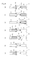
- the feeding star wheel 11 feeds the containers 3 onto the mounts 4 in the feed position A in Figure 1 (see Figures 1 and 8(a) ).
- the supporting member 37 is retracted above the container 3 by the action of the first cam 54, and the picker 41 is also retracted to the level of the lower end of the outer periphery of the mandrel 23 by the action of the third cam 75 and is in the open state.
- the container 3 passes through the feed position A as the labeler main unit 5 rotates, and then, the supporting member 37 is lowered by the action of the first cam 54 and is fitted onto the mouth 3B of the container 3, and the container 3 is vertically held between the mount 4 and the supporting member 37 (see Figure 8(b) ).
- the picker 41 is lowered to the level of the mouth 3B of the container 3 by the action of the third cam 75 (see Figure 8(c) ).
- the second cam 65 of the open/close mechanism 58 that opens and closes the picker 41 maintains the picker 41 in the open state, and therefore, there is a clearance between the container 3 and the picker 41.
- the label feeding means 12 is in the waiting state after the rotary cutter 22 cuts the film label 2 fed by the feed roller 21 to a predetermined length, the film labels 2 having the predetermined length (full label FL) are held on the outer surface of the feeding drum 24, and the applying roller 25 applies the UV curing adhesive to the rear end of each full label FL (see Figure 2 ).
- the servo motor 44 makes the mandrel 23 rotate.
- the suction holes 23A of the mandrel 23 are in communication with the operating suction means via the negative pressure pipe 43, so that the feeding drum 24 releases the full label FL and passes the full label FL to the mandrel 23 in such a manner that the lower end of the full label FL is located at substantially the same level as the lower end of the mandrel 23. Since the mandrel 23 is revolving, the full label FL passed to the mandrel 23 wraps around the outer surface of the mandrel 23 and is sucked and held thereto (see Figure 8(c) ).
- the front end and the rear end of the full label FL are overlaid one on another, and the UV curing adhesive bonds the front end and the rear end overlaid one on another. That is, the film label 2 held on the outer surface of the mandrel 23 has a cylindrical shape.
- the container 3 then moves to the hardening position D as the labeler main unit 5 rotates, the UV irradiating means 26 emits UV rays to the overlaid front and rear ends (UV curing adhesive) of the full label FL in the cylindrical shape held on the mandrel 23 (see Figures 1 and 8(c) ). Then, the front and rear ends of the full label FL are firmly bonded to each other by the hardened UV curing adhesive, and the full label FL in the cylindrical shape is held on the outer surface of the mandrel 23.
- UV curing adhesive UV curing adhesive
- the picker 41 is raised by the action of the third cam 75 until the lower end of the picker 41 is at substantially the same level as the lower end of the full label FL held on the mandrel 23 (the raising limit position), and the picker 41, which has been open, is closed by the action of the open/close mechanism 58 (see Figure 8(d) ).
- the suction holes 57B of the picker 41 come into communication with the operating suction means, so that the picker 41 sucks the full label FL, and the communication between the suction holes 23A of the mandrel 23 and the suction means is cut off.
- the full label FL is released from the mandrel 23, and the outer periphery of the lower end of the full label FL is sucked and held to the holding parts 57A of the picker 41 (see Figure 8(d) ).
- the third cam follower 74 moves along the first cam groove 82A of the cam plate 82, so that the picker 41 holding the full label FL is lowered to the lower limit position on the mount 4, and thus the lower end of the full label FL is lowered to the lower end of the barrel 3A of the container 3 (see Figures 1 and 8(e) ).
- the full label FL in the cylindrical shape held by the picker 41 is fitted around the whole of the barrel 3A of the container 3.
- the film label 2 having the longer vertical dimension (full label FL) is shaped into the cylindrical shape and then fitted around the barrel 3A of the container 3.
- the container 3 around which the full label FL is fitted is then fed to a shrink tunnel (not shown) by the discharging conveyer 16, where the full label FL is heated to shrink and be tightly fitted on the barrel 3A of the container 3 (see Figure 1 ).
- the film label 2 in the label feeding means 12 is replaced with the half label HL.
- the adjustment mechanism 56 in the fitting section E lowers the cam plate 82 so that the second cam groove 82B is engaged with the third cam follower 74 (see Figure 7 ).
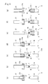
- the picker 41 holding the lower end of the outer periphery of the half label HL fits the half label HL around the barrel 3A of the container 3 on the mount 4 with the lower end of the half label HL lowered to the level close to the middle of the barrel 3A, which is higher than the lower end of the barrel 3A (see figs, 9(d) and 9(f) ).
- the hot air blower nozzle 84 blows hot air to an upper part of the half label HL fitted around the barrel 3A of the container 3 (see Figure 9(e) ).
- the upper part of the half label HL fitted around the barrel 3A of the container 3 shrinks and is temporarily secured to the upper end of the barrel 3A of the container 3.
- the half label HL is sucked and held to the outer periphery of the lower end of the mandrel 23 with the lower end of the half label HL being at substantially the same level as the lower end of the mandrel 23 and thereby shaped into a cylindrical shape (see Figure 9(d) ).
- the picker 41 then sucks and holds the outer periphery of the lower end of the half label HL in the cylindrical shape on the mandrel 23 (see Figure 9(d) ) and is lowered along the second cam groove 82B of the cam plate 82, thereby fitting the half label HL around the part of the barrel 3A of the container 3 higher than the middle thereof (see Figures 9(d) to 9(f) ).
- the picker 41 fits the half label HL around the container 3 as described above, since the vertical dimension of the half label HL is approximately a half of the vertical dimension of the full label FL described earlier, so that a negative pressure leakage occurs through the suction holes 24A in the upper part of the feeding drum 24 holding the half label HL and through the section holes 23A in the upper part of the mandrel 23 holding the half label HL.
- the half label HL is held on the outer periphery of the feeding drum 24 and the mandrel 23 while allowing for the negative pressure leakage through the suction holes 24A in the upper part of the feeding drum 24 and the suction holes 23A in the upper part of the mandrel 23.
- the negative pressure leakage through the suction holes 24A in the upper part of the feeding drum 24 and the suction holes 23A in the upper part of the mandrel 23 may be prevented.
- the communication state of the negative pressure channel (not shown) that connects the suction holes 24A in the upper part of the feeding drum 24 and the suction holes 23A in the upper part of the mandrel 23 to the suction means can be switched by an electromagnetic switching valve depending on the dimension of the half label HL.
- the raised position of the picker 41 does not change, whether the picker 41 is to fit the full label FL and the half label HL around the container 3, and the lowered position (fitting level) of the picker 41 can be changed by the adjustment mechanism 56 switching the level of the cam plate 82 between the raised position and the lowered position, whether the picker 41 is holding the outer periphery of the lower end of the full label FL or the half label HL.
- the single apparatus can handle both the full label FL and the half label HL and fit the labels around the containers 3 having the same outer diameter.
- the film label fitting apparatus 1 provided according to this embodiment is highly versatile.
- the picker 41 holds the outer periphery of the lower end of the full label FL and the half label HL in this embodiment, the present invention is not limited thereto, and the picker 41 may hold the outer periphery of a part of the film label slightly above the lower end thereof to fit the film label around the container 3. However, the picker 41 preferably holds the outer periphery of the lower end of the full label FL and the half label HL, because the possibility of failures, such as the film label 2 being caught on the container 3 and curling up during fitting, can be minimized.
- the present invention is not limited to this arrangement, and the mandrel 23 and the picker 41 may be disposed below the mount 4, and the picker 41 may carry the film label 2 in the cylindrical shape upward and fit the film label 2 around the container 3 from below.
- the picker 41 sucks and holds the outer periphery of the upper end of the film label 2 in the cylindrical shape on the mandrel 23, and the diameters of the mount 4 and the mandrel 23 are slightly larger than the diameter of the container 3 to be handled.
- a cam mechanism is used as the raising and lowering mechanism 55 for raising and lowering the picker 41.
- the raising and lowering mechanism 55 for raising and lowering the picker 41 may be a servo motor-driven mechanism or a linear drive mechanism such as one shown in Figure 10 .
- a vertical raising and lowering guide 107 is disposed so as to extend from a mount 104 to the level of a mandrel 123, and a supporting member 108 is attached to the raising and lowering guide 107 in such a manner that the supporting member 108 can be raised and lowered.
- a picker 141 having a pair of left and right arms 157 is attached to the supporting member 108 in such a manner that the picker 141 can be opened and closed.
- the picker 141 can be raised and lowered by a linear drive source 109 raising and lowering the supporting member 108, and the level of the lowering limit of the picker 141 can be switched depending on whether the full label FL or the half label HL is handled in the fitting section E described above.
- a rotary actuator 128 and a pair of gears 129 provided on base parts of the arms 157 are used to open and close the arms 157 of the picker 141.
- the picker 141 can be opened and closed at a desired position by the rotary actuator 128 rotating the gears 129.
- components corresponding to those in the first embodiment described earlier are denoted by the same reference numerals plus 100.
- the embodiment shown in Figure 10 can provide the same effects and advantages as those of the first embodiment described earlier.
- the UV curing adhesive is used to bond the front and rear ends of the film label 2.
- the front and rear ends of the film label 2 may be bonded to each other with a hot melt adhesive or laser.
Landscapes
- Labeling Devices (AREA)
Applications Claiming Priority (2)
| Application Number | Priority Date | Filing Date | Title |
|---|---|---|---|
| JP2011122593 | 2011-05-31 | ||
| PCT/JP2012/056973 WO2012165004A1 (fr) | 2011-05-31 | 2012-03-19 | Dispositif de fixation d'étiquettes en forme de film |
Publications (3)
| Publication Number | Publication Date |
|---|---|
| EP2716558A1 true EP2716558A1 (fr) | 2014-04-09 |
| EP2716558A4 EP2716558A4 (fr) | 2014-10-15 |
| EP2716558B1 EP2716558B1 (fr) | 2017-07-19 |
Family
ID=47258870
Family Applications (1)
| Application Number | Title | Priority Date | Filing Date |
|---|---|---|---|
| EP12792298.7A Not-in-force EP2716558B1 (fr) | 2011-05-31 | 2012-03-19 | Dispositif de fixation d'étiquettes en forme de film |
Country Status (3)
| Country | Link |
|---|---|
| EP (1) | EP2716558B1 (fr) |
| JP (1) | JPWO2012165004A1 (fr) |
| WO (1) | WO2012165004A1 (fr) |
Cited By (1)
| Publication number | Priority date | Publication date | Assignee | Title |
|---|---|---|---|---|
| EP2956369B1 (fr) * | 2013-02-15 | 2020-12-02 | Sacmi Verona S.P.A. | Procédé pour la production d'étiquettes-manchons et dispositif pour leur production |
Families Citing this family (2)
| Publication number | Priority date | Publication date | Assignee | Title |
|---|---|---|---|---|
| JP6146609B2 (ja) * | 2013-04-15 | 2017-06-14 | シブヤマシナリー株式会社 | ラベラ |
| JP6436830B2 (ja) * | 2015-03-26 | 2018-12-12 | レンゴー株式会社 | 樹脂製ラベル装着装置および樹脂製ラベル装着方法 |
Citations (5)
| Publication number | Priority date | Publication date | Assignee | Title |
|---|---|---|---|---|
| US4412876A (en) | 1981-07-07 | 1983-11-01 | Automated Packaging Systems, Inc. | Labeling apparatus |
| DE19716079A1 (de) | 1996-06-20 | 1998-04-09 | Ulrich Klotzki | Verfahren zum Etikettieren von Behältern, insbesondere Flaschen, sowie Etikettiermaschine |
| US6474390B1 (en) | 1998-09-14 | 2002-11-05 | Protection Decoration Conditionnement Europe S.A. | Machine for placing labeling sleeves on bottles |
| US7060143B1 (en) | 1999-04-30 | 2006-06-13 | Krones Ag | Method and device for applying wrap-around labels to objects |
| JP2007314234A (ja) | 2006-05-29 | 2007-12-06 | Shibuya Kogyo Co Ltd | 筒状ラベル嵌装装置 |
Family Cites Families (7)
| Publication number | Priority date | Publication date | Assignee | Title |
|---|---|---|---|---|
| JP3881421B2 (ja) * | 1997-04-01 | 2007-02-14 | 住友商事マシネックス株式会社 | シュリンク包装機及びシュリンク包装体の製造方法 |
| DE10002401A1 (de) * | 1999-04-30 | 2001-01-11 | Krones Ag | Verfahren und Vorrichtung zum Aufbringen von Etikettenhülsen auf Gegenstände |
| JP4777532B2 (ja) * | 2000-09-13 | 2011-09-21 | 株式会社フジシールインターナショナル | ラベル装着装置 |
| JP4414644B2 (ja) * | 2002-11-08 | 2010-02-10 | 株式会社タハラ | 包装用筒状ラベルの嵌着装置 |
| JP4307064B2 (ja) * | 2002-12-26 | 2009-08-05 | 株式会社フジシールインターナショナル | フィルム嵌挿装置 |
| ITMO20050230A1 (it) | 2005-09-12 | 2007-03-13 | Sacmi Labelling S P A | Apparato e metodo per ottenere etichette |
| JP4907261B2 (ja) | 2006-08-23 | 2012-03-28 | 株式会社フジシールインターナショナル | フィルム被嵌装置 |
-
2012
- 2012-03-19 JP JP2013517900A patent/JPWO2012165004A1/ja active Pending
- 2012-03-19 WO PCT/JP2012/056973 patent/WO2012165004A1/fr not_active Ceased
- 2012-03-19 EP EP12792298.7A patent/EP2716558B1/fr not_active Not-in-force
Patent Citations (5)
| Publication number | Priority date | Publication date | Assignee | Title |
|---|---|---|---|---|
| US4412876A (en) | 1981-07-07 | 1983-11-01 | Automated Packaging Systems, Inc. | Labeling apparatus |
| DE19716079A1 (de) | 1996-06-20 | 1998-04-09 | Ulrich Klotzki | Verfahren zum Etikettieren von Behältern, insbesondere Flaschen, sowie Etikettiermaschine |
| US6474390B1 (en) | 1998-09-14 | 2002-11-05 | Protection Decoration Conditionnement Europe S.A. | Machine for placing labeling sleeves on bottles |
| US7060143B1 (en) | 1999-04-30 | 2006-06-13 | Krones Ag | Method and device for applying wrap-around labels to objects |
| JP2007314234A (ja) | 2006-05-29 | 2007-12-06 | Shibuya Kogyo Co Ltd | 筒状ラベル嵌装装置 |
Non-Patent Citations (1)
| Title |
|---|
| See also references of WO2012165004A1 |
Cited By (1)
| Publication number | Priority date | Publication date | Assignee | Title |
|---|---|---|---|---|
| EP2956369B1 (fr) * | 2013-02-15 | 2020-12-02 | Sacmi Verona S.P.A. | Procédé pour la production d'étiquettes-manchons et dispositif pour leur production |
Also Published As
| Publication number | Publication date |
|---|---|
| JPWO2012165004A1 (ja) | 2015-02-23 |
| EP2716558A4 (fr) | 2014-10-15 |
| EP2716558B1 (fr) | 2017-07-19 |
| WO2012165004A1 (fr) | 2012-12-06 |
Similar Documents
| Publication | Publication Date | Title |
|---|---|---|
| JP5247724B2 (ja) | スリーブ状の箔材料からなる連続した平らなストリップ(strip)からスリーブ状の箔包装体を形成する装置 | |
| CA2852287C (fr) | Dispositif d'etiquetage de contenants | |
| JP6050256B2 (ja) | 筒形ラベル移送用の真空移送要素と方法複数の筒形ラベル移送用の真空移送要素と方法 | |
| EP2716558A1 (fr) | Dispositif de fixation d'étiquettes en forme de film | |
| EP1749747A1 (fr) | Dispositif de traitement de fermetures | |
| JP7252440B2 (ja) | 容器搬送装置 | |
| JP5434750B2 (ja) | ラベラー | |
| US9828202B2 (en) | Apparatus and method for forming a stack of advertising material compilations | |
| US7845379B2 (en) | Labeling machine for labeling containers, such as bottles or cans, especially sardine cans | |
| JP5730906B2 (ja) | フィルム被嵌装置 | |
| JP6003043B2 (ja) | 樹脂製ラベル装着装置および樹脂製ラベル装着方法 | |
| JP4306869B2 (ja) | ラベル拡開機構 | |
| JP4306863B2 (ja) | ラベル装着装置 | |
| WO2024079504A1 (fr) | Module d'étiquetage à démarrage optimisé | |
| JP4134826B2 (ja) | 溶着装置 | |
| EP2300215B1 (fr) | Dispositif de formation d'enveloppe feuille de type manchon à partir d'une bande plate de matériau feuille | |
| JP5689675B2 (ja) | ラベル装着装置 | |
| EP1497179A1 (fr) | Procede et dispositif permettant de former des groupes d'emballages d'un produit alimentaire pateux | |
| JP2020001747A (ja) | ラベラ | |
| BE623438A (fr) |
Legal Events
| Date | Code | Title | Description |
|---|---|---|---|
| PUAI | Public reference made under article 153(3) epc to a published international application that has entered the european phase |
Free format text: ORIGINAL CODE: 0009012 |
|
| 17P | Request for examination filed |
Effective date: 20131112 |
|
| AK | Designated contracting states |
Kind code of ref document: A1 Designated state(s): AL AT BE BG CH CY CZ DE DK EE ES FI FR GB GR HR HU IE IS IT LI LT LU LV MC MK MT NL NO PL PT RO RS SE SI SK SM TR |
|
| TPAC | Observations filed by third parties |
Free format text: ORIGINAL CODE: EPIDOSNTIPA |
|
| DAX | Request for extension of the european patent (deleted) | ||
| A4 | Supplementary search report drawn up and despatched |
Effective date: 20140911 |
|
| RIC1 | Information provided on ipc code assigned before grant |
Ipc: B65B 53/00 20060101AFI20140905BHEP Ipc: B65B 59/00 20060101ALI20140905BHEP Ipc: B65C 3/06 20060101ALI20140905BHEP |
|
| 17Q | First examination report despatched |
Effective date: 20150622 |
|
| GRAP | Despatch of communication of intention to grant a patent |
Free format text: ORIGINAL CODE: EPIDOSNIGR1 |
|
| INTG | Intention to grant announced |
Effective date: 20170302 |
|
| GRAS | Grant fee paid |
Free format text: ORIGINAL CODE: EPIDOSNIGR3 |
|
| GRAA | (expected) grant |
Free format text: ORIGINAL CODE: 0009210 |
|
| AK | Designated contracting states |
Kind code of ref document: B1 Designated state(s): AL AT BE BG CH CY CZ DE DK EE ES FI FR GB GR HR HU IE IS IT LI LT LU LV MC MK MT NL NO PL PT RO RS SE SI SK SM TR |
|
| REG | Reference to a national code |
Ref country code: GB Ref legal event code: FG4D |
|
| REG | Reference to a national code |
Ref country code: CH Ref legal event code: EP |
|
| REG | Reference to a national code |
Ref country code: IE Ref legal event code: FG4D |
|
| REG | Reference to a national code |
Ref country code: AT Ref legal event code: REF Ref document number: 910136 Country of ref document: AT Kind code of ref document: T Effective date: 20170815 |
|
| REG | Reference to a national code |
Ref country code: DE Ref legal event code: R096 Ref document number: 602012034779 Country of ref document: DE |
|
| REG | Reference to a national code |
Ref country code: NL Ref legal event code: MP Effective date: 20170719 |
|
| REG | Reference to a national code |
Ref country code: LT Ref legal event code: MG4D |
|
| REG | Reference to a national code |
Ref country code: AT Ref legal event code: MK05 Ref document number: 910136 Country of ref document: AT Kind code of ref document: T Effective date: 20170719 |
|
| PG25 | Lapsed in a contracting state [announced via postgrant information from national office to epo] |
Ref country code: NL Free format text: LAPSE BECAUSE OF FAILURE TO SUBMIT A TRANSLATION OF THE DESCRIPTION OR TO PAY THE FEE WITHIN THE PRESCRIBED TIME-LIMIT Effective date: 20170719 Ref country code: FI Free format text: LAPSE BECAUSE OF FAILURE TO SUBMIT A TRANSLATION OF THE DESCRIPTION OR TO PAY THE FEE WITHIN THE PRESCRIBED TIME-LIMIT Effective date: 20170719 Ref country code: SE Free format text: LAPSE BECAUSE OF FAILURE TO SUBMIT A TRANSLATION OF THE DESCRIPTION OR TO PAY THE FEE WITHIN THE PRESCRIBED TIME-LIMIT Effective date: 20170719 Ref country code: HR Free format text: LAPSE BECAUSE OF FAILURE TO SUBMIT A TRANSLATION OF THE DESCRIPTION OR TO PAY THE FEE WITHIN THE PRESCRIBED TIME-LIMIT Effective date: 20170719 Ref country code: AT Free format text: LAPSE BECAUSE OF FAILURE TO SUBMIT A TRANSLATION OF THE DESCRIPTION OR TO PAY THE FEE WITHIN THE PRESCRIBED TIME-LIMIT Effective date: 20170719 Ref country code: NO Free format text: LAPSE BECAUSE OF FAILURE TO SUBMIT A TRANSLATION OF THE DESCRIPTION OR TO PAY THE FEE WITHIN THE PRESCRIBED TIME-LIMIT Effective date: 20171019 Ref country code: LT Free format text: LAPSE BECAUSE OF FAILURE TO SUBMIT A TRANSLATION OF THE DESCRIPTION OR TO PAY THE FEE WITHIN THE PRESCRIBED TIME-LIMIT Effective date: 20170719 |
|
| PG25 | Lapsed in a contracting state [announced via postgrant information from national office to epo] |
Ref country code: PL Free format text: LAPSE BECAUSE OF FAILURE TO SUBMIT A TRANSLATION OF THE DESCRIPTION OR TO PAY THE FEE WITHIN THE PRESCRIBED TIME-LIMIT Effective date: 20170719 Ref country code: ES Free format text: LAPSE BECAUSE OF FAILURE TO SUBMIT A TRANSLATION OF THE DESCRIPTION OR TO PAY THE FEE WITHIN THE PRESCRIBED TIME-LIMIT Effective date: 20170719 Ref country code: LV Free format text: LAPSE BECAUSE OF FAILURE TO SUBMIT A TRANSLATION OF THE DESCRIPTION OR TO PAY THE FEE WITHIN THE PRESCRIBED TIME-LIMIT Effective date: 20170719 Ref country code: GR Free format text: LAPSE BECAUSE OF FAILURE TO SUBMIT A TRANSLATION OF THE DESCRIPTION OR TO PAY THE FEE WITHIN THE PRESCRIBED TIME-LIMIT Effective date: 20171020 Ref country code: RS Free format text: LAPSE BECAUSE OF FAILURE TO SUBMIT A TRANSLATION OF THE DESCRIPTION OR TO PAY THE FEE WITHIN THE PRESCRIBED TIME-LIMIT Effective date: 20170719 Ref country code: BG Free format text: LAPSE BECAUSE OF FAILURE TO SUBMIT A TRANSLATION OF THE DESCRIPTION OR TO PAY THE FEE WITHIN THE PRESCRIBED TIME-LIMIT Effective date: 20171019 Ref country code: IS Free format text: LAPSE BECAUSE OF FAILURE TO SUBMIT A TRANSLATION OF THE DESCRIPTION OR TO PAY THE FEE WITHIN THE PRESCRIBED TIME-LIMIT Effective date: 20171119 |
|
| REG | Reference to a national code |
Ref country code: DE Ref legal event code: R097 Ref document number: 602012034779 Country of ref document: DE |
|
| PG25 | Lapsed in a contracting state [announced via postgrant information from national office to epo] |
Ref country code: CZ Free format text: LAPSE BECAUSE OF FAILURE TO SUBMIT A TRANSLATION OF THE DESCRIPTION OR TO PAY THE FEE WITHIN THE PRESCRIBED TIME-LIMIT Effective date: 20170719 Ref country code: RO Free format text: LAPSE BECAUSE OF FAILURE TO SUBMIT A TRANSLATION OF THE DESCRIPTION OR TO PAY THE FEE WITHIN THE PRESCRIBED TIME-LIMIT Effective date: 20170719 Ref country code: DK Free format text: LAPSE BECAUSE OF FAILURE TO SUBMIT A TRANSLATION OF THE DESCRIPTION OR TO PAY THE FEE WITHIN THE PRESCRIBED TIME-LIMIT Effective date: 20170719 |
|
| PLBE | No opposition filed within time limit |
Free format text: ORIGINAL CODE: 0009261 |
|
| STAA | Information on the status of an ep patent application or granted ep patent |
Free format text: STATUS: NO OPPOSITION FILED WITHIN TIME LIMIT |
|
| PG25 | Lapsed in a contracting state [announced via postgrant information from national office to epo] |
Ref country code: SM Free format text: LAPSE BECAUSE OF FAILURE TO SUBMIT A TRANSLATION OF THE DESCRIPTION OR TO PAY THE FEE WITHIN THE PRESCRIBED TIME-LIMIT Effective date: 20170719 Ref country code: EE Free format text: LAPSE BECAUSE OF FAILURE TO SUBMIT A TRANSLATION OF THE DESCRIPTION OR TO PAY THE FEE WITHIN THE PRESCRIBED TIME-LIMIT Effective date: 20170719 Ref country code: SK Free format text: LAPSE BECAUSE OF FAILURE TO SUBMIT A TRANSLATION OF THE DESCRIPTION OR TO PAY THE FEE WITHIN THE PRESCRIBED TIME-LIMIT Effective date: 20170719 |
|
| 26N | No opposition filed |
Effective date: 20180420 |
|
| PG25 | Lapsed in a contracting state [announced via postgrant information from national office to epo] |
Ref country code: SI Free format text: LAPSE BECAUSE OF FAILURE TO SUBMIT A TRANSLATION OF THE DESCRIPTION OR TO PAY THE FEE WITHIN THE PRESCRIBED TIME-LIMIT Effective date: 20170719 |
|
| REG | Reference to a national code |
Ref country code: CH Ref legal event code: PL |
|
| GBPC | Gb: european patent ceased through non-payment of renewal fee |
Effective date: 20180319 |
|
| PG25 | Lapsed in a contracting state [announced via postgrant information from national office to epo] |
Ref country code: MC Free format text: LAPSE BECAUSE OF FAILURE TO SUBMIT A TRANSLATION OF THE DESCRIPTION OR TO PAY THE FEE WITHIN THE PRESCRIBED TIME-LIMIT Effective date: 20170719 |
|
| REG | Reference to a national code |
Ref country code: BE Ref legal event code: MM Effective date: 20180331 |
|
| REG | Reference to a national code |
Ref country code: IE Ref legal event code: MM4A |
|
| PG25 | Lapsed in a contracting state [announced via postgrant information from national office to epo] |
Ref country code: LU Free format text: LAPSE BECAUSE OF NON-PAYMENT OF DUE FEES Effective date: 20180319 |
|
| PG25 | Lapsed in a contracting state [announced via postgrant information from national office to epo] |
Ref country code: IE Free format text: LAPSE BECAUSE OF NON-PAYMENT OF DUE FEES Effective date: 20180319 |
|
| PG25 | Lapsed in a contracting state [announced via postgrant information from national office to epo] |
Ref country code: LI Free format text: LAPSE BECAUSE OF NON-PAYMENT OF DUE FEES Effective date: 20180331 Ref country code: CH Free format text: LAPSE BECAUSE OF NON-PAYMENT OF DUE FEES Effective date: 20180331 Ref country code: GB Free format text: LAPSE BECAUSE OF NON-PAYMENT OF DUE FEES Effective date: 20180319 Ref country code: BE Free format text: LAPSE BECAUSE OF NON-PAYMENT OF DUE FEES Effective date: 20180331 |
|
| PG25 | Lapsed in a contracting state [announced via postgrant information from national office to epo] |
Ref country code: FR Free format text: LAPSE BECAUSE OF NON-PAYMENT OF DUE FEES Effective date: 20180331 |
|
| PG25 | Lapsed in a contracting state [announced via postgrant information from national office to epo] |
Ref country code: MT Free format text: LAPSE BECAUSE OF NON-PAYMENT OF DUE FEES Effective date: 20180319 |
|
| PG25 | Lapsed in a contracting state [announced via postgrant information from national office to epo] |
Ref country code: TR Free format text: LAPSE BECAUSE OF FAILURE TO SUBMIT A TRANSLATION OF THE DESCRIPTION OR TO PAY THE FEE WITHIN THE PRESCRIBED TIME-LIMIT Effective date: 20170719 |
|
| PG25 | Lapsed in a contracting state [announced via postgrant information from national office to epo] |
Ref country code: PT Free format text: LAPSE BECAUSE OF FAILURE TO SUBMIT A TRANSLATION OF THE DESCRIPTION OR TO PAY THE FEE WITHIN THE PRESCRIBED TIME-LIMIT Effective date: 20170719 Ref country code: HU Free format text: LAPSE BECAUSE OF FAILURE TO SUBMIT A TRANSLATION OF THE DESCRIPTION OR TO PAY THE FEE WITHIN THE PRESCRIBED TIME-LIMIT; INVALID AB INITIO Effective date: 20120319 |
|
| PG25 | Lapsed in a contracting state [announced via postgrant information from national office to epo] |
Ref country code: MK Free format text: LAPSE BECAUSE OF NON-PAYMENT OF DUE FEES Effective date: 20170719 Ref country code: CY Free format text: LAPSE BECAUSE OF FAILURE TO SUBMIT A TRANSLATION OF THE DESCRIPTION OR TO PAY THE FEE WITHIN THE PRESCRIBED TIME-LIMIT Effective date: 20170719 |
|
| PG25 | Lapsed in a contracting state [announced via postgrant information from national office to epo] |
Ref country code: AL Free format text: LAPSE BECAUSE OF FAILURE TO SUBMIT A TRANSLATION OF THE DESCRIPTION OR TO PAY THE FEE WITHIN THE PRESCRIBED TIME-LIMIT Effective date: 20170719 |
|
| PGFP | Annual fee paid to national office [announced via postgrant information from national office to epo] |
Ref country code: DE Payment date: 20220203 Year of fee payment: 11 |
|
| PGFP | Annual fee paid to national office [announced via postgrant information from national office to epo] |
Ref country code: IT Payment date: 20220210 Year of fee payment: 11 |
|
| REG | Reference to a national code |
Ref country code: DE Ref legal event code: R119 Ref document number: 602012034779 Country of ref document: DE |
|
| PG25 | Lapsed in a contracting state [announced via postgrant information from national office to epo] |
Ref country code: DE Free format text: LAPSE BECAUSE OF NON-PAYMENT OF DUE FEES Effective date: 20231003 |
|
| PG25 | Lapsed in a contracting state [announced via postgrant information from national office to epo] |
Ref country code: IT Free format text: LAPSE BECAUSE OF NON-PAYMENT OF DUE FEES Effective date: 20230319 |