EP2716845A2 - Zylinderschloss, elektronische Vorrichtung und Bargeldverzeichnis - Google Patents
Zylinderschloss, elektronische Vorrichtung und Bargeldverzeichnis Download PDFInfo
- Publication number
- EP2716845A2 EP2716845A2 EP20130185136 EP13185136A EP2716845A2 EP 2716845 A2 EP2716845 A2 EP 2716845A2 EP 20130185136 EP20130185136 EP 20130185136 EP 13185136 A EP13185136 A EP 13185136A EP 2716845 A2 EP2716845 A2 EP 2716845A2
- Authority
- EP
- European Patent Office
- Prior art keywords
- outer shell
- rotatable plug
- rotation arresting
- arresting member
- cylinder lock
- Prior art date
- Legal status (The legal status is an assumption and is not a legal conclusion. Google has not performed a legal analysis and makes no representation as to the accuracy of the status listed.)
- Withdrawn
Links
- 230000037361 pathway Effects 0.000 claims abstract description 24
- 238000003780 insertion Methods 0.000 claims abstract description 7
- 230000037431 insertion Effects 0.000 claims abstract description 7
- 230000035807 sensation Effects 0.000 description 18
- 230000007246 mechanism Effects 0.000 description 7
- 230000006870 function Effects 0.000 description 4
- 230000008859 change Effects 0.000 description 2
- 230000004048 modification Effects 0.000 description 2
- 238000012986 modification Methods 0.000 description 2
- 239000011347 resin Substances 0.000 description 2
- 229920005989 resin Polymers 0.000 description 2
- 230000007704 transition Effects 0.000 description 2
- 230000015572 biosynthetic process Effects 0.000 description 1
- 230000001413 cellular effect Effects 0.000 description 1
- 230000006835 compression Effects 0.000 description 1
- 238000007906 compression Methods 0.000 description 1
- 230000000694 effects Effects 0.000 description 1
- 239000013013 elastic material Substances 0.000 description 1
- 238000000605 extraction Methods 0.000 description 1
- 239000000463 material Substances 0.000 description 1
- 239000002184 metal Substances 0.000 description 1
- 230000000149 penetrating effect Effects 0.000 description 1
- 239000013585 weight reducing agent Substances 0.000 description 1
Images




Classifications
-
- E—FIXED CONSTRUCTIONS
- E05—LOCKS; KEYS; WINDOW OR DOOR FITTINGS; SAFES
- E05B—LOCKS; ACCESSORIES THEREFOR; HANDCUFFS
- E05B27/00—Cylinder locks or other locks with tumbler pins or balls that are set by pushing the key in
-
- E—FIXED CONSTRUCTIONS
- E05—LOCKS; KEYS; WINDOW OR DOOR FITTINGS; SAFES
- E05B—LOCKS; ACCESSORIES THEREFOR; HANDCUFFS
- E05B65/00—Locks or fastenings for special use
- E05B65/46—Locks or fastenings for special use for drawers
- E05B65/461—Locks or fastenings for special use for drawers for cash drawers
-
- E—FIXED CONSTRUCTIONS
- E05—LOCKS; KEYS; WINDOW OR DOOR FITTINGS; SAFES
- E05B—LOCKS; ACCESSORIES THEREFOR; HANDCUFFS
- E05B29/00—Cylinder locks and other locks with plate tumblers which are set by pushing the key in
-
- Y—GENERAL TAGGING OF NEW TECHNOLOGICAL DEVELOPMENTS; GENERAL TAGGING OF CROSS-SECTIONAL TECHNOLOGIES SPANNING OVER SEVERAL SECTIONS OF THE IPC; TECHNICAL SUBJECTS COVERED BY FORMER USPC CROSS-REFERENCE ART COLLECTIONS [XRACs] AND DIGESTS
- Y10—TECHNICAL SUBJECTS COVERED BY FORMER USPC
- Y10T—TECHNICAL SUBJECTS COVERED BY FORMER US CLASSIFICATION
- Y10T70/00—Locks
- Y10T70/70—Operating mechanism
- Y10T70/7441—Key
- Y10T70/7486—Single key
- Y10T70/7508—Tumbler type
- Y10T70/7559—Cylinder type
- Y10T70/7588—Rotary plug
Definitions
- the present invention relates to cylinder locks and is applicable in particular to cylinder locks for desk drawers and cabinets, lockers, and electronic devices such as cash registers.
- Electronic devices such as cash registers, which are used to perform calculations related to currency as well as to store, deposit, and withdrawal cash, are equipped with a mechanical cylinder lock on the drawer so the withdrawal of cash is possible even in the event of a loss of power.
- Some such cylinder locks are provided with a click mechanism (detent mechanism) which, upon rotation of the key, provides tactile and audible feedback with a click sensation (the sensation a detent provides) to notify of a given rotational position of the key.
- Patent Literature 1 discloses a click mechanism which generates a click sensation. According to PTL 1, since assembly by hand is difficult when the click mechanism is small, assembly of the cylinder lock is made easier by enlarging the size of the click mechanism as much as possible.
- the present invention has been made in view of the above problem, and aims to provide a cylinder lock that has few parts and is capable of being miniaturized in addition to being capable of generating a click sensation when a key is turned.
- the cylinder lock according to the present invention includes: an outer shell provided with a cylindrical hollow portion therein; a rotatable plug rotatably positioned in the hollow portion of the outer shell and provided with a keyway along a rotational axis of the rotatable plug, the keyway being for accommodating a key; a rotation arresting member which arrests rotation of the rotatable plug by projecting out from the rotatable plug and entering a pathway provided in the outer shell; a biasing member which biases the rotation arresting member in a direction in which the rotation arresting member projects out from the rotatable plug; and a beveled edge provided at an end of the rotation arresting member and having a beveled surface which intersects a rotational direction of the rotatable plug, wherein insertion of the key into the keyway causes the beveled edge, along with the rotation arresting member, to move in a direction from the outer shell toward the rotatable plug to a position at which the beveled
- the outer shell may further include a click portion which accommodates the beveled edge that projects out from the rotatable plug.
- the rotation arresting member may include a key hole which accommodates the key, and the key hole and the keyway may be positioned to overlap each other.
- the rotatable plug may include a plurality of the rotation arresting members, and at least one of the rotation arresting members may be provided with the beveled edge.
- an electronic device may include: an outer shell provided with a cylindrical hollow portion therein; a rotatable plug rotatably positioned in the hollow portion of the outer shell and provided with a keyway along a rotational axis of the rotatable plug, the keyway being for accommodating a key; a rotation arresting member which arrests rotation of the rotatable plug by projecting out from the rotatable plug and entering a pathway provided in the outer shell; a biasing member which biases the rotation arresting member in a direction in which the rotation arresting member projects out from the rotatable plug; and a beveled edge provided at an end of the rotation arresting member and having a beveled surface which intersects a rotational direction of the rotatable plug, wherein insertion of the key into the keyway causes the beveled edge, along with the rotation arresting member, to move in a direction from the outer shell toward the rotatable plug to a position at which the beveled edge and an inner circumference of the outer shell intersect
- a cash register may include: an outer shell provided with a cylindrical hollow portion therein; a rotatable plug rotatably positioned in the hollow portion of the outer shell and provided with a keyway along a rotational axis of the rotatable plug, the keyway being for accommodating a key; a rotation arresting member which arrests rotation of the rotatable plug by projecting out from the rotatable plug and entering a pathway provided in the outer shell; a biasing member which biases the rotation arresting member in a direction in which the rotation arresting member projects out from the rotatable plug; and a beveled edge provided at an end of the rotation arresting member and having a beveled surface which intersects a rotational direction of the rotatable plug, wherein insertion of the key into the keyway causes the beveled edge, along with the rotation arresting member, to move in a direction from the outer shell toward the rotatable plug to a position at which the beveled edge and an inner circumference of the outer shell
- a cash register may include (i) a first lock including: an outer shell provided with a cylindrical hollow portion therein; a rotatable plug rotatably positioned in the hollow portion of the outer shell and provided with a keyway along a rotational axis of the rotatable plug, the keyway being for accommodating a key; a rotation arresting member which arrests rotation of the rotatable plug by projecting out from the rotatable plug and entering a pathway provided in the outer shell; a biasing member which biases the rotation arresting member in a direction in which the rotation arresting member projects out from the rotatable plug; and a beveled edge provided at an end of the rotation arresting member and having a beveled surface which intersects a rotational direction of the rotatable plug, wherein insertion of the key into the keyway causes the beveled edge, along with the rotation arresting member, to move in a direction from the outer shell toward the rotatable plug to a position at which the beveled edge and
- the present invention makes it possible to provide a small, light-weight cylinder lock having few parts.
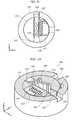
- FIG. 1 is a schematic perspective view showing the appearance of the cylinder lock.
- FIG. 2 is a schematic perspective view showing the appearance of the rotatable plug.
- FIG. 3 is a schematic perspective view showing a cross-section of the cylinder lock in the x-y plane while the key is not inserted in the cylinder lock and the rotation arresting member is in a projected state.
- FIG. 4 is a schematic perspective view showing a cross-section of the cylinder lock in the x-y plane while a key is inserted in the cylinder lock and the rotation arresting member is in a recessed state.
- the cylinder lock 100 includes an outer shell 101, a rotatable plug 102, a rotation arresting member 103, a biasing member 104, a beveled edge 105, and a pathway 106.
- the outer shell 101 has a cylindrical hollow portion therein for accommodating the rotatable plug 102.
- the outer shell 101 is a cylindrical member having an internal cylindrical hollow portion.
- the outer shell 101 includes a flange 111 which prevents the housed rotatable plug 102 from sliding out in the extraction direction of a key 200 (positive direction on the z axis in FIG. 1 ).
- the flange 111 is provided completely around the outer shell 101 projecting inward from the inner circumference edge of the outer shell 101.
- the rotatable plug 102 has a cylindrical external shape and is provided along the rotational axis of the keyway 121 for insertion of the key 200.
- the rotatable plug 102 is so positioned in the outer shell 101 as to be rotatable relative to the outer shell 101.
- the rotational axis of the rotatable plug 102 and the central axis of the cylindrical internal hollow portion of the outer shell 101 are arranged on the same axis.
- the rotatable plug 102 is rotatably held about the rotational axis coinciding with the central axis of the internal hollow portion of the outer shell 101.
- FIG. 5 is a perspective view of the rotation arresting member.
- the rotation arresting member 103 is arranged to cross the boundary of the outer shell 101 and the rotatable plug 102 by projecting out from the rotatable plug 102 into the pathway 106 provided in the outer shell 101, thereby arresting rotation of the rotatable plug 102 with respect to the outer shell 101 (as FIG. 3 shows).
- the rotation arresting member 103 is a member having a rectangular cross-section external shape located along a radial direction (x axis direction in the drawings) centered on the rotational axis and provided with a first surface 131 and a second surface 132 opposite the first surface 131 which, when the rotation arresting member 103 is projected out from the rotatable plug 102, intersect the plane of the boundary of the outer shell 101 and the rotatable plug 102.
- the rotation arresting member 103 is positioned to be extendable in the radial direction (x axis direction in the drawings) and move in a rotation arresting member housing area 107 of the rotatable plug 102 in the radial direction (x axis direction in the drawings).
- the first surface 131 or the second surface 132 is pushed against the outer shell 101 and rotation of the rotatable plug 102 is arrested by the rotation arresting member 103 being positioned to intersect the boundary between the outer shell 101 and the rotatable plug 102.
- the rotation arresting member 103 includes a key hole 133 which accommodates the key 200.
- the key hole 133 is positioned to overlap the keyway.
- the key hole 133 is arranged in a positioned such that the key inserted in the keyway 121 is also inserted in the key hole 133.
- the key hole 133 is of a size which allows for movement of the rotation arresting member 103, which moves in the radial direction (x axis direction in the drawings), in the negative x axis direction shown in FIG. 4 while the key 200 is inserted (as FIG. 4 shows).
- the rotation arresting member 103 recedes in the rotatable plug 102 as a result of the key 200 being inserted in the keyway 121. More specifically, the rotation arresting member 103 recedes from a state in which the rotation arresting member 103 is projecting out (as FIG. 3 shows), to a state in which the beveled edge 105 intersects the inner circumference of the outer shell 101 (as FIG. 4 shows).
- the rotation arresting member 103 is provided with an abutting surface portion 134 at an end opposite the beveled edge 105. The abutting surface portion 134 abuts a key inserted into the keyway 121.
- the rotation arresting member 103 includes an engaging portion 135 which protrudes from the first surface 131 and extends in a direction (y axis direction in the drawings) which intersects the moving direction (x axis direction in the drawings) of the rotation arresting member 103.
- the engaging portion 135 is connected to the biasing member 104 and receives the biasing force from the biasing member 104.
- the biasing member 104 biases the rotation arresting member 103 in the radial direction.
- the biasing member 104 is a spring positioned in a biasing member positioning space 141 formed between the engaging portion 135 of the rotation arresting member 103 and the rotatable plug 102.
- the biasing member 104 is positioned so as to bias the rotation arresting member 103 in a direction from the rotatable plug 102 toward the outer shell 101.
- biasing member 104 may directly bias the rotation arresting member 103 without the use of the engaging portion 135.
- a compression spring, pulling spring, plate spring, resin spring, or an elastic material such as rubber may be used as the biasing member 104.
- the beveled edge 105 is provided at the end of the rotation arresting member 103 near the outer shell 101.
- the beveled edge 105 aligns in a position intersecting the inner circumference of the outer shell 101 as a result of a key being inserted in the keyway 121 and thereby moving the rotation arresting member 103 into the rotatable plug 102.
- the beveled edge 105 includes a beveled surface 151 which intersects the rotational direction of the rotatable plug 102.
- the beveled surface 151 is pressed against the outer shell 101 as a result of the key 200 being inserted and the rotatable plug 102 being rotated relative to the outer shell 101.
- the rotation arresting member 103 recedes into the rotatable plug 102 against the biasing force of the biasing member 104 as a result of the rotatable plug 102 being turned by the inserted key 200.
- the beveled surface 151 is not limited to a flat surface, and may be a curved surface.
- the pathway 106 is provided at the inner periphery of the outer shell 101, and is of a size that can accommodate a portion of the rotation arresting member 103.
- the pathway 106 accommodates the beveled edge 105, and furthermore, is of a size that can accommodate a portion of the rotation arresting member 103.
- the pathway 106 is provided penetrating the outer shell 101 in the radial direction. Configuring the pathway 106 which penetrates the outer shell 101 in this way simplifies the formation of the outer shell 101.
- the pathway 106 is illustrated as a through hole which penetrates the outer shell 101, but the pathway 106 may be a hole with one end closed, as is shown in FIG. 13 .
- the rotation arresting member housing area 107 is provided in the rotatable plug 102 and is capable of accommodating the rotation arresting member 103. It should be noted that in Embodiment 1, the rotation arresting member housing area 107 penetrates through the rotatable plug 102, but this example is not intended to be limiting. For example, one end of the rotation arresting member housing area 107 may be closed.
- FIG. 3 and FIG. 6 show, when the key 200 is not inserted in the keyway 121, the rotation arresting member 103 is positioned in the pathway 106 and the first surface 131 and the second surface 132 intersect the boundary of the outer shell 101 and the rotatable plug 102.
- the beveled edge 105 penetrates the pathway 106 provided in the outer shell 101 in its entirety.
- the rotatable plug 102 cannot be rotated relative to the outer shell 101 since the first surface 131 or the second surface 132 of the rotation arresting member 103 will push against the outer shell 101.
- the cylinder lock 100 is in a locked state.
- FIG. 4 and FIG. 7 show, the key 200 abuts the abutting surface portion 134 of the rotation arresting member 103 as a result of being inserted in the keyway 121, and the rotation arresting member 103 moves into the rotatable plug 102 to a position at which the beveled edge 105 intersects the inner circumference of the outer shell 101.
- the rotation arresting member 103 rotates about the center of the rotating axis along with the rotation of the rotatable plug 102.
- the beveled surface 151 of the beveled edge 105 pushes against the outer shell 101, and the rotation arresting member 103 moves into the rotatable plug 102 until the beveled edge 105 is housed in the rotation arresting member housing area 107 of the rotatable plug 102, as is shown in FIG. 8 .
- the click sensation generated as the portion of the beveled edge 105 pushed against the outer shell 101 by the biasing member 104 transitions from the beveled surface 151 to the tip surface is perceived by the operator.
- the rotatable plug 102 rotates smoothly while the rotation arresting member 103 including the beveled edge 105 is housed in the rotation arresting member housing area 107, like in the state shown in FIG. 8 .
- the biasing force of the biasing member 104 forces the rotation arresting member 103 to enter a second pathway 106, as FIG. 9 shows.
- the click sensation as the portion of the beveled edge 105 pushed against the outer shell 101 by the biasing member 104 transitions from the tip surface to the beveled surface 151 and from the beveled surface 151 to the first surface 131 or the second surface 132 is perceived by the operator operating the key 200.
- the abutting surface portion 134 collides with the key 200, there are instances in which this collision is perceived as a click sensation as well.
- the cylinder lock 100 according to Embodiment 1 can provide a click sensation while performing unlocking and locking operations. Moreover, since the rotation arresting member 103 which arrests the rotation of the rotatable plug 102 also functions to generate a click sensation, it is possible to reduce the number of parts of the cylinder lock 100 and achieve a small, light-weight cylinder lock 100.
- the above cylinder lock 100 may be structured like is shown in FIG. 10 .
- the outer shell 101 may include a click portion 108 which is a space that accommodates the beveled edge 105 which projects out from the rotatable plug 102.
- the click portion 108 generates a click sensation upon the beveled edge 105 entering therein, but the click portion 108 is of a size that holds the beveled edge 105 at a position which intersects the inner circumference of the outer shell 101. Moreover, similar to the pathway 106, the click portion 108 may be a through-hole which penetrates the outer shell 101.
- the cylinder lock 100 it is possible to provide the cylinder lock 100 with a position which generates a click sensation in a position other than the unlocked position or the locked position, and it is possible provide the cylinder lock 100 with functions other than locking and unlocking functions.
- the above cylinder lock 100 may include a plurality of the rotation arresting members 103, as FIG. 11 shows. Moreover, among the plurality of rotation arresting members 103, at least one of the rotation arresting members 103 may be provided with a beveled edge 105 at the tip end thereof, and all other rotation arresting members 103 not provided with the beveled edge 105 may enter inside the rotatable plug 102 as a result of the key 200 being inserted.
- the number of the above pathways 106 provided in the outer shell 101 corresponds to the number of rotation arresting members 103.
- one of the rotation arresting members 103 is provided with the beveled edge 105, but any given number or all of the rotation arresting members 103 may be provided with the beveled edge 105.
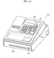
- FIG. 12 is an external perspective view schematically depicting an example of the cash register.
- the cash register 300 is provided with the cylinder lock 100 as a first lock 191.
- the cylinder lock 100 includes the outer shell 101 provided with the pathway 106, the rotatable plug 102 provided with the rotation arresting member housing area 107 and the keyway 121, the rotation arresting member 103 which moves into the rotatable plug 102 by the key 200 being inserted, the biasing member 104 which biases the rotation arresting member 103 in a projecting direction from the rotatable plug 102, and the beveled edge 105 provided with the beveled surface 151 at the tip end of the rotation arresting member 103 for generating a click sensation.
- the first lock 191 is attached to a drawer 301 used for holding cash, and is used for locking and unlocking the drawer 301.
- the key 200 is insertable into and removable from the first lock 191 when the first lock 191 is in a locked state as well as when the first lock 191 is in an unlocked state.
- the cash register 300 also includes the cylinder lock 100 as a second lock 192.
- the second lock 192 includes, in the outer shell 101, the click portion 108 which is a space that accommodates the beveled edge 105 which projects out from the rotatable plug 102.
- the second lock 192 is attached above an array of keys 302 of the cash register 300, and is used to switch between modes of the cash register 300. More specifically, in the cash register 300, the second lock 192 can be unlocked by inserting the key in the second lock 192 after the key 200 is inserted in the first lock 191 and the first lock 191 is unlocked. In other words, the first lock 191 and the second lock 192 use the same key 200. Then, going by the click sensation from the key 200 inserted in the second lock 192 and the symbols and/or characters displayed on the screen of the cash register 300 (not shown in the Drawings), the operator turns the key 200 to select a desired mode.
- symbols and/or characters which correspond to the position of the pathway 106 included in the outer shell 101 or the position of the click portion 108 like shown in FIG. 10 are displayed on the screen of the cash register 300.
- the operator turns the key 200 while watching the symbols and/or characters indicating the desired mode, and stops turning the key using the click sensation when the beveled edge 105 enters the pathway 106 or the click portion 108 as a guide.
- the number of pathways 106, rotation arresting member housing areas 107, and click portions 108 used is not limited to a certain number, and, for example, may correspond to the number of modes required for the electronic device (cash register inclusive) equipped with the cylinder lock 100.
- the outer shell 101 may be structurally combined with the housing of the electronic device, such as the cash register.
- the biasing member 104 is exemplified as a coil spring, but the biasing member 104 may, for example, be a different kind of spring such as a leaf spring. Moreover, the material of the biasing member 104 is not limited to metal or resin.
- the present invention can be used in locks for lockers or desks, electronic devices such as cash registers, information terminals, and cellular phones for security purposes and/or switching modes.
Landscapes
- Physics & Mathematics (AREA)
- Electromagnetism (AREA)
- Cash Registers Or Receiving Machines (AREA)
- Lock And Its Accessories (AREA)
Applications Claiming Priority (1)
| Application Number | Priority Date | Filing Date | Title |
|---|---|---|---|
| JP2012221542A JP2014074277A (ja) | 2012-10-03 | 2012-10-03 | シリンダ錠、電子機器、レジスター |
Publications (1)
| Publication Number | Publication Date |
|---|---|
| EP2716845A2 true EP2716845A2 (de) | 2014-04-09 |
Family
ID=49230564
Family Applications (1)
| Application Number | Title | Priority Date | Filing Date |
|---|---|---|---|
| EP20130185136 Withdrawn EP2716845A2 (de) | 2012-10-03 | 2013-09-19 | Zylinderschloss, elektronische Vorrichtung und Bargeldverzeichnis |
Country Status (4)
| Country | Link |
|---|---|
| US (1) | US20140090429A1 (de) |
| EP (1) | EP2716845A2 (de) |
| JP (1) | JP2014074277A (de) |
| CN (1) | CN103711370A (de) |
Families Citing this family (1)
| Publication number | Priority date | Publication date | Assignee | Title |
|---|---|---|---|---|
| JP6615624B2 (ja) * | 2016-01-20 | 2019-12-04 | 東芝テック株式会社 | ロックシステム、扉構造、および電子機器 |
Citations (1)
| Publication number | Priority date | Publication date | Assignee | Title |
|---|---|---|---|---|
| JPH0674767U (ja) | 1993-03-31 | 1994-10-21 | 株式会社アルファ | シリンダ錠装置 |
Family Cites Families (25)
| Publication number | Priority date | Publication date | Assignee | Title |
|---|---|---|---|---|
| US1430176A (en) * | 1918-05-27 | 1922-09-26 | Marguerite G Campbell | Lock |
| US2061456A (en) * | 1931-11-30 | 1936-11-17 | Falk Morris | Removable plug lock |
| US2460709A (en) * | 1947-02-25 | 1949-02-01 | Eugene M Navarro | Lock mechanism |
| US2729092A (en) * | 1951-02-19 | 1956-01-03 | Ingersoll Ltd | Plug and cylinder type lock mechanism |
| US2667785A (en) * | 1952-05-05 | 1954-02-02 | Librascope Inc | Two key cylinder lock |
| US2831338A (en) * | 1953-09-01 | 1958-04-22 | Yale & Towne Mfg Co | Side bar lock |
| CH537509A (fr) * | 1971-02-24 | 1973-05-31 | Parlier Roger | Serrure à clé |
| FI56049C (fi) * | 1974-06-17 | 1979-11-12 | Waertsilae Oy Ab | Cylinderlaos |
| US4015458A (en) * | 1975-11-21 | 1977-04-05 | Leonard Mercurio | Wafer type tumbler lock construction having individual side bar tumbler inhibiting means |
| US4272975A (en) * | 1979-07-06 | 1981-06-16 | Hudson Lock, Inc. | Cylinder lock with key removable core |
| JPS62194374A (ja) * | 1986-02-19 | 1987-08-26 | 株式会社クローバー | 錠装置 |
| US4723427A (en) * | 1986-03-21 | 1988-02-09 | Medeco Security Locks Inc. | Symmetrical side bar lock and key therefor |
| US4811579A (en) * | 1987-11-27 | 1989-03-14 | Ncr Corporation | Cash drawer release mechanism |
| JPH0721776Y2 (ja) * | 1989-11-10 | 1995-05-17 | 株式会社東海理化電機製作所 | シリンダ錠 |
| DE9012267U1 (de) * | 1990-08-25 | 1991-12-19 | Wolter, Heinz, 5067 Kürten | Schließzylinder an Mikroelektroschaltern |
| US5375444A (en) * | 1991-05-20 | 1994-12-27 | Shield Security Systems, Inc. | Multi-key core lock assembly |
| US5355703A (en) * | 1991-09-12 | 1994-10-18 | Briggs & Stratton Corporation | Cylindrical lock with cam down retaining tumbler |
| JPH087646B2 (ja) * | 1992-10-29 | 1996-01-29 | インターナショナル・ビジネス・マシーンズ・コーポレイション | 携帯型コンピュータ用据置装置 |
| US5295376A (en) * | 1993-04-22 | 1994-03-22 | Fort Lock Corporation | Zero clearance lock |
| JPH1113318A (ja) * | 1997-06-20 | 1999-01-19 | Alpha Corp | キープレート及びその製造方法 |
| AT409019B (de) * | 1999-05-26 | 2002-05-27 | Evva Werke | Flachschlüssel und zylinderschloss |
| US6446475B1 (en) * | 2000-06-12 | 2002-09-10 | Itt Manufacturing Enterprises, Inc. | Switchlock assembly with snap-in cam |
| TWM259038U (en) * | 2004-07-21 | 2005-03-11 | Chuen-Yi Hung | Lock with master key |
| US6968716B1 (en) * | 2004-08-31 | 2005-11-29 | Sinox Co., Ltd. | Connection lock executing locking operation without keys |
| US8621902B2 (en) * | 2007-06-13 | 2014-01-07 | Schlage Lock Company Llc | Master keying system and method for programmable lock cylinder assemblies |
-
2012
- 2012-10-03 JP JP2012221542A patent/JP2014074277A/ja active Pending
-
2013
- 2013-09-19 EP EP20130185136 patent/EP2716845A2/de not_active Withdrawn
- 2013-09-24 US US14/034,628 patent/US20140090429A1/en not_active Abandoned
- 2013-09-27 CN CN201310450504.9A patent/CN103711370A/zh active Pending
Patent Citations (1)
| Publication number | Priority date | Publication date | Assignee | Title |
|---|---|---|---|---|
| JPH0674767U (ja) | 1993-03-31 | 1994-10-21 | 株式会社アルファ | シリンダ錠装置 |
Also Published As
| Publication number | Publication date |
|---|---|
| US20140090429A1 (en) | 2014-04-03 |
| CN103711370A (zh) | 2014-04-09 |
| JP2014074277A (ja) | 2014-04-24 |
Similar Documents
| Publication | Publication Date | Title |
|---|---|---|
| US8111511B2 (en) | Electronic device physical security component | |
| JP2011258205A (ja) | スクロール式タッチキーパッド | |
| US8640512B2 (en) | Lock structure for electronic device | |
| US8079237B2 (en) | Locking assembly for electronic device | |
| US10638721B2 (en) | Pet cage door | |
| US20210025196A1 (en) | Interchangeable core lock assemblies | |
| AU2010280367B2 (en) | Lock assembly | |
| EP2716845A2 (de) | Zylinderschloss, elektronische Vorrichtung und Bargeldverzeichnis | |
| US8085532B2 (en) | Electronic device | |
| US11628804B2 (en) | Steering lock device | |
| CN209742559U (zh) | 一种挂锁 | |
| CN203589548U (zh) | 断路器程序锁联锁机构 | |
| EP3690909A1 (de) | Schutzschalter | |
| CN112885629A (zh) | 电子装置 | |
| CN219068609U (zh) | 翻盖机构和电器设备 | |
| WO2020236068A1 (en) | Locking device | |
| US8212166B2 (en) | Switch assembly | |
| CN212656673U (zh) | 一种电子锁 | |
| CN211038147U (zh) | 叶片锁芯以及锁具 | |
| EP3839178B1 (de) | Möbelschloss mit drehbar gelagertem elektronikgehäuse und verfahren zu dessen bedienung | |
| JP6411824B2 (ja) | 錠装置 | |
| CN101990012A (zh) | 便携式电子装置 | |
| US8113020B2 (en) | Lock and electronic device using the same | |
| JP5424334B2 (ja) | 電子機器及びスライド装置 | |
| JP2011204551A (ja) | 可逆形電磁接触器 |
Legal Events
| Date | Code | Title | Description |
|---|---|---|---|
| PUAI | Public reference made under article 153(3) epc to a published international application that has entered the european phase |
Free format text: ORIGINAL CODE: 0009012 |
|
| AK | Designated contracting states |
Kind code of ref document: A2 Designated state(s): AL AT BE BG CH CY CZ DE DK EE ES FI FR GB GR HR HU IE IS IT LI LT LU LV MC MK MT NL NO PL PT RO RS SE SI SK SM TR |
|
| AX | Request for extension of the european patent |
Extension state: BA ME |
|
| STAA | Information on the status of an ep patent application or granted ep patent |
Free format text: STATUS: THE APPLICATION IS DEEMED TO BE WITHDRAWN |
|
| 18D | Application deemed to be withdrawn |
Effective date: 20160401 |