EP2716859B1 - Moteur tubulaire avec support pour un élément de fixation - Google Patents
Moteur tubulaire avec support pour un élément de fixation Download PDFInfo
- Publication number
- EP2716859B1 EP2716859B1 EP13186819.2A EP13186819A EP2716859B1 EP 2716859 B1 EP2716859 B1 EP 2716859B1 EP 13186819 A EP13186819 A EP 13186819A EP 2716859 B1 EP2716859 B1 EP 2716859B1
- Authority
- EP
- European Patent Office
- Prior art keywords
- tubular motor
- clamp
- head
- motor according
- pin
- Prior art date
- Legal status (The legal status is an assumption and is not a legal conclusion. Google has not performed a legal analysis and makes no representation as to the accuracy of the status listed.)
- Active
Links
Images



Classifications
-
- E—FIXED CONSTRUCTIONS
- E06—DOORS, WINDOWS, SHUTTERS, OR ROLLER BLINDS IN GENERAL; LADDERS
- E06B—FIXED OR MOVABLE CLOSURES FOR OPENINGS IN BUILDINGS, VEHICLES, FENCES OR LIKE ENCLOSURES IN GENERAL, e.g. DOORS, WINDOWS, BLINDS, GATES
- E06B9/00—Screening or protective devices for wall or similar openings, with or without operating or securing mechanisms; Closures of similar construction
- E06B9/02—Shutters, movable grilles, or other safety closing devices, e.g. against burglary
- E06B9/08—Roll-type closures
- E06B9/11—Roller shutters
- E06B9/17—Parts or details of roller shutters, e.g. suspension devices, shutter boxes, wicket doors, ventilation openings
- E06B9/174—Bearings specially adapted therefor
-
- E—FIXED CONSTRUCTIONS
- E06—DOORS, WINDOWS, SHUTTERS, OR ROLLER BLINDS IN GENERAL; LADDERS
- E06B—FIXED OR MOVABLE CLOSURES FOR OPENINGS IN BUILDINGS, VEHICLES, FENCES OR LIKE ENCLOSURES IN GENERAL, e.g. DOORS, WINDOWS, BLINDS, GATES
- E06B9/00—Screening or protective devices for wall or similar openings, with or without operating or securing mechanisms; Closures of similar construction
- E06B9/24—Screens or other constructions affording protection against light, especially against sunshine; Similar screens for privacy or appearance; Slat blinds
- E06B9/40—Roller blinds
- E06B9/42—Parts or details of roller blinds, e.g. suspension devices, blind boxes
- E06B9/50—Bearings specially adapted therefor
-
- E—FIXED CONSTRUCTIONS
- E06—DOORS, WINDOWS, SHUTTERS, OR ROLLER BLINDS IN GENERAL; LADDERS
- E06B—FIXED OR MOVABLE CLOSURES FOR OPENINGS IN BUILDINGS, VEHICLES, FENCES OR LIKE ENCLOSURES IN GENERAL, e.g. DOORS, WINDOWS, BLINDS, GATES
- E06B9/00—Screening or protective devices for wall or similar openings, with or without operating or securing mechanisms; Closures of similar construction
- E06B9/56—Operating, guiding or securing devices or arrangements for roll-type closures; Spring drums; Tape drums; Counterweighting arrangements therefor
- E06B9/68—Operating devices or mechanisms, e.g. with electric drive
- E06B9/72—Operating devices or mechanisms, e.g. with electric drive comprising an electric motor positioned inside the roller
Definitions
- the present invention relates to a tubular motor.
- tubular motors for domotic applications are used, for instance, in automation systems for blinds and curtains (the latter especially for outdoor applications), and the name “tubular motor” results from their configuration suited to allow them to be inserted into the winding tube of the blinds or curtains.
- the blinds allow to close, in use, an opening defined in a masonry structure; they are thus installed in a specific niche obtained in a portion of said structure, in particular in the upper part which defines the opening itself.
- a frame for blinds comprising two plates, to one of which the head of the tubular motor is fixed, is inserted into this niche.
- the blinds are similarly installed in a box fixed to the masonry structure.
- the same installation solutions may be adopted for curtains.
- Figure 1 shows an embodiment of a known solution, in which a firm fastening is obtained by coupling the tubular motor to one of two fastening plates by means of an anchoring support applied to the first plate and a bracket defined on the second one.
- the operator installing blinds or curtains provided with tubular motor should then firstly arrange the fastening of the plate and the tubular motor, i.e. mount the bracket and the anchoring support, respectively; afterwards, the operator should insert the tubular motor (with the winding tube) into the niche or box, and finally fix the tubular motor to the plate.
- the head of the tubular motor may be fixed to the plate by applying screws (or other similar elements) or by snap-fitting (as in the known solution shown in figure 1 ), thus taking advantage of the conjugate configuration of the bracket on the plate and of the anchoring support on the motor head.
- Document EP2390457 describes a tubular motor comprising a head detachable from the tube of the tubular motor itself.
- a fastening plate At one side of the installation niche for the curtain associated to the tubular motor there is a fastening plate. Interface components allow an operator to fix the head to the fastening plate.
- the head is in turn applied to the tube of the tubular motor.
- Such head is in particular designed to fit a multitude of tubes of tubular motors.
- the limited, predetermined angular fastening positions of the tubular motor can make the installation inconvenient and indeed under these conditions accessing some components may be difficult for the installer.
- the specific object of the present invention is to provide a tubular motor for blinds or curtains which may be fixed directly onto the plate.
- the inventive idea underlying the invention consists in fixing the tubular motor to the plate by means of a different, original head of the motor itself.
- a tubular motor for domotic applications in particular for operating curtains or blinds, according to the present invention, comprises a tube and a head at one end of the tube, wherein a clamp adapted to receive and restrain an external pin for fixing the tubular motor is integrated in head.
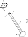
- reference numeral 5 indicates as a whole a winding roller for curtains or blinds obtained by means of an internally hollow, hexagonal section member; thereby, roller 5 may accommodate the tubular motor for domotic applications comprising a tube 3 and a head 1 at one end of the tube 3 itself in addition to other components.
- Tube 3 comprises an internally hollow cylinder, adapted to contain a plurality of devices functional to actuating the winding roller. These devices (not shown in the figure) may include: the electric motor, the limit stop unit, the ratio motor and the roller feeding cap. In particular, the latter is coupled to the winding roller 5 and turns while feeding the roller therewith when responding to the actuation of the electric motor.
- tubular motor thus means the assembly of tube 3, head 1 and the functional actuating devices contained in tube 3.
- the winding roller 5 and the tubular motor are fixed at their respective ends to the two sides of the frame 4 for blinds, the latter being applied in the housing niche or box in which the blinds or curtains will be installed.
- the side of frame 4 comprises a pin 40 for anchoring the tubular motor thereto by means of head 1, as clearly shown in the following description.
- Head 1 at the end of tube 3 integrates a clamp 2 adapted to receive and restrain pin 40 in order to fix the tubular motor to the side of frame 4.
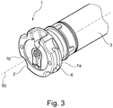
- head 1 A preferred embodiment of head 1 is shown in figure 3 , the head 1 comprising:
- head 1 is defined in one piece and that the flat surface of side 1b comprises, in turn, a first surface and a crown which surrounds the mentioned first surface defined in relief therewith.
- the first surface includes a seat (e.g. an appropriately shaped cavity) to accommodate clamp 2: the latter is adjacent to the first surface itself when it is inserted within it.
- the crown is shaped so as to allow a simple assembly of the tubular motor; moreover, it comprises appropriate holes to allow electric wires to pass, which from the outside need to reach the tubular motor for powering purposes.
- head 1 comprises a seat which has a conjugate shape with respect to the shape of the clamp, so as to be able to accommodate it inside.
- Figure 3 again shows a preferred embodiment of the tubular motor according to the present invention, wherein clamp 2 perfectly mates with the seat on the second side 1b of head 1; according to this embodiment, the seat houses clamp 2 completely so that it does not protrude from head 1. Furthermore, figure 3 (as well as figure 6 ) shows an opening for inserting/extracting clamp 2 in/from head 1; the opening is located at the above mentioned flat surface of head 1 so that it is easy to insert and extract clamp 2 for its replacement or its arrangement according to the appropriate mode or manner (see below).
- Figure 5 shows the head 1 of the tubular motor according to the present invention, where clamp 2 is associated with a screw 13, the latter comprising a threaded shank 13a and a head 13b adjacent to the threaded shank; thereby, the clamp 2 itself can be restrained to pin 40, when the screw is fastened.
- the clamp comprises an arched anchoring portion 2a adapted to receive and surround pin 40 and restraining portions 10a, 10b spaced apart form each other with respective holes 12a, 12b.
- only one of these two holes preferably, a first hole 12b
- the other preferably, a second through hole 12a
- Inserting the threaded shank 13a into the second through hole 12a is facilitated by the nominal diameter of the second shank which is slightly larger than the first.
- the holes 12a and 12b collimate and are indeed aligned along the same axis 60.
- the threading of the first hole 12b is characterized in one direction (e.g. leftwards) coinciding with that of screw 13.
- the threaded shank is inserted into the second through hole 12a and screw 13 is then fastened in the threaded hole 12b in order to restrain clamp 2 to pin 40.
- screw 13 is engaged by means of the threaded shank 13b within hole 12b, even crossing the through hole 12a.
- Fastening screw 13 causes the flexion and/or bending of the anchoring portion 2a and the approach of the first portion 10a to the second portion 10b.
- the seat on the head 1 of the tubular motor advantageously allows to accommodate clamp 2 in two different modes; in the first mode, the position of the clamp is turned by 180° with respect to the position in the second mode. Therefore, when the tubular motor is installed with head 1 applied to an opposite end with respect to a previous case, agreement between the direction of the threading of hole 12a and that of screw 13 is maintained.
- tubular motor can be simply fixed to the pin both on the right side and the left side of frame 4 by means of the same head.
- These two alternatives are possible by extracting clamp 2 from its seat in the head, turning it by 180° and finally inserting it again into the seat.
- Figures 7 and 8 show a preferred embodiment of the clamp according to the present invention.
- it comprises a first arched anchoring portion 2a adapted to receive and surround the pin, and two restraining portions 10a and 10b joined to the ends of the first anchoring portion, respectively.
- the two restraining portions 10a and 10b comprise a first and a second tab, respectively: the first tab comprises, in turn, a through hole, while the second comprises a threaded hole to allow the above-described screw to pass and be restrained, respectively.
- notch 14 at the end of clamp 2.
- fastening screw 13 in the threaded hole of the second tab produces a slight flexion of the second tab itself which thus approaches the first tab. This operation allows the anchoring portion 2a to restrain pin 40 by tightening itself about it.
- the mentioned notch 14 facilitates the flexion of the tab and the consequent restraining of pin 40.
- the head of a tubular motor is the stationary reaction member when the latter turns feeding the winding tube therewith. Therefore, restraining it to the pin very firmly is very important.
- the inner surface 10, which is the surface in contact with pin 40 in use has a plurality of radial protrusions. Thereby, when clamp 2 is restrained, such protrusions exert a greater radial force on the surface of pin 40.
- the radial protrusions 11 preferably comprise a knurling.
- the symmetry axis 50 of the anchoring portion 2a of clamp 2 coincides with the symmetry axis of the tubular motor.
- head 1 comprises at least a first passage 6 and at least a second passage 7, both conceived to make the first threaded hole 12b and the second threaded hole 12a on the restraining portions 10b and 10a accessible from the outside, respectively.
- screw 13 can be introduced into the specific hole (6 or 7) and then, by means of a screwdriver, it can be fastened thus restraining clamp 2.
- This configuration in addition to the clamp which may be repositioned by 180° in the seat of head 1, allows the motor to be positioned in any angular position, with evident advantage in terms of installation simplicity and rapidity.
- the embodiment in figure 4 shows a head according to the present invention, in which from the side position of the tubular motor, i.e. the typical position in which the tubular motor is fixed in the niche or box, the access to screw 13 is direct.
- first passage 6 and the second passage 7 on head 2 and the first threaded hole 12a and the second threaded hole 12b of the restraining portions 10a and 10b are aligned along an axis 60.
- screw 13 can be inserted into the appropriate hole and thus be directly accessed to restrain clamp 2.
- head 1 is made of plastic material
- clamp 2 is made of metal material, in particular steel, obtained by means of a sintering process, for instance.
- a metal clamp 2 ensures good keeping of pin 40, in terms of restraint of pin 40 and holding of screw 13 fastened into the corresponding threading.
- the metal knurling allows to exert a good radial force on pin 40, the threading obtained on hole 12b (when the latter is made of metal material) ensures better reliability and safety in the operation of fastening screw 13. Furthermore, both features ensure good durability of a head for a tubular motor according to the present invention over time.
Landscapes
- Engineering & Computer Science (AREA)
- Structural Engineering (AREA)
- Architecture (AREA)
- Civil Engineering (AREA)
- Operating, Guiding And Securing Of Roll- Type Closing Members (AREA)
- Curtains And Furnishings For Windows Or Doors (AREA)
- Motor Or Generator Frames (AREA)
- Iron Core Of Rotating Electric Machines (AREA)
Claims (15)
- Moteur tubulaire pour applications de domotique, notamment pour l'actionnement de rideaux ou stores, comprenant un tube (3) et une tête (1) à un bout dudit tube (3), caractérisé en ce qu'il comprend un collier (2) adapté pour recevoir et fixer une cheville externe (40) pour la fixation du moteur tubulaire, ledit collier (2) étant incorporé dans ladite tête (1).
- Moteur tubulaire selon la revendication 1, ladite tête (1) comprenant :- un premier côté (1a) dudit tube (3), et- un deuxième côté (1b), situé face au premier, à ladite cheville (40), doté d'une surface plate ;
ledit collier (2) étant adjacent à ladite surface plate. - Moteur tubulaire selon la revendication 1 ou 2, ladite tête (1) comprenant un siège adapté pour recevoir ledit collier (2), et ledit siège ayant une forme conjuguée relativement à la forme dudit collier (2).
- Moteur tubulaire selon la revendication 3, ledit siège contenant entièrement ledit collier (2), de façon qu'il ne dépasse pas de ladite tête (1).
- Moteur tubulaire selon la revendication 3 ou 4, ladite tête (1) possédant une ouverture pour l'insertion et l'extraction dudit collier (2), ladite ouverture étant située à ladite surface plate.
- Moteur tubulaire selon la revendication 3 ou 4 ou 5, ledit siège étant adapté pour recevoir ledit collier (2) d'une première façon et d'une deuxième façon, et dans ladite première façon la position dudit collier (2) est retournée de 180° relativement à la position dudit collier (2) dans ladite deuxième façon.
- Moteur tubulaire selon une quelconque des revendications précédentes, ledit collier (2) étant associé avec une vis (13), ladite vis (13) étant adaptée pour retenir ledit collier (2) lorsqu'il est fixé.
- Moteur tubulaire selon une quelconque des revendications précédentes, ledit collier (2) comprenant une première partie d'ancrage (2a) ayant une forme arquée adaptée pour recevoir et entourer ladite cheville (4) et deux parties de retenue (10a, 10b) jointes respectivement aux bouts de ladite première partie d'ancrage (2a), chacune desdites parties de retenue (10a, 10b) possédant respectivement un premier orifice traversant (12a) et un deuxième orifice fileté (12b) pour l'insertion et l'accouplement avec ladite vis (13).
- Moteur tubulaire selon la revendication 8, l'axe de symétrie (50) de ladite première partie d'ancrage (2a) coïncidant avec l'axe de symétrie du moteur tubulaire.
- Moteur tubulaire selon la revendication 8 ou 9, ladite première partie d'ancrage (2a) comprenant une surface interne (10), ladite surface interne (10), en contact, en cours d'usage, avec ladite cheville (40), possédant une pluralité de saillies radiales (11).
- Moteur tubulaire selon la revendication 8 ou 9 ou 10, ladite tête (1) comprenant, sur un premier côté, au moins un premier passage (6) adapté afin que ledit premier orifice traversant (12a) et ledit deuxième orifice fileté (12b) desdites parties de retenue (10a, 10b) soient accessibles de l'extérieur.
- Moteur tubulaire selon la revendication 11, ladite tête (1) comprenant, sur un deuxième côté, situé face au premier côté, au moins un deuxième passage (7) adapté afin que ledit premier orifice traversant (12a) et ledit deuxième orifice fileté (12b) desdites parties de retenue (10a, 10b) soient accessibles de l'extérieur.
- Moteur tubulaire selon la revendication 12, dans lequel :- ledit premier passage (6) et ledit deuxième passage (7) et ladite tête (1), et- ledit premier orifice traversant (12a) et ledit deuxième orifice fileté (12b) desdites parties de retenue (10a, 10b) sont alignés le long d'un axe (60).
- Moteur tubulaire selon la revendication 13, ledit axe (60) étant perpendiculaire à l'axe dudit tube (30) et/ou à l'axe de ladite cheville (40), et l'axe dudit tube (30) et l'axe de ladite cheville (40) coïncident de préférence.
- Moteur tubulaire selon une quelconque des revendications précédentes, ladite tête (1) étant réalisé en matière plastique, et ledit collier (2) étant réalisé en métal, notamment en acier.
Applications Claiming Priority (1)
| Application Number | Priority Date | Filing Date | Title |
|---|---|---|---|
| IT000051A ITCO20120051A1 (it) | 2012-10-03 | 2012-10-03 | Motore tubolare con supporto per un elemento di fissaggio |
Publications (2)
| Publication Number | Publication Date |
|---|---|
| EP2716859A1 EP2716859A1 (fr) | 2014-04-09 |
| EP2716859B1 true EP2716859B1 (fr) | 2018-03-14 |
Family
ID=47222209
Family Applications (1)
| Application Number | Title | Priority Date | Filing Date |
|---|---|---|---|
| EP13186819.2A Active EP2716859B1 (fr) | 2012-10-03 | 2013-10-01 | Moteur tubulaire avec support pour un élément de fixation |
Country Status (3)
| Country | Link |
|---|---|
| EP (1) | EP2716859B1 (fr) |
| CN (1) | CN103711420B (fr) |
| IT (1) | ITCO20120051A1 (fr) |
Families Citing this family (3)
| Publication number | Priority date | Publication date | Assignee | Title |
|---|---|---|---|---|
| US11268322B2 (en) * | 2016-10-21 | 2022-03-08 | Crestron Electronics, Inc. | Shade motor with power supplied by brackets |
| IT201800003023A1 (it) * | 2018-02-26 | 2019-08-26 | Cherubini Spa | Testa di connessione di un apparato di azionamento per tende da sole avvolgibili o chiusure oscuranti |
| DE102018009935B4 (de) * | 2018-12-20 | 2021-05-20 | Roma Kg | Antriebsvorrichtung für eine Gebäudeöffnungsverschattung |
Family Cites Families (6)
| Publication number | Priority date | Publication date | Assignee | Title |
|---|---|---|---|---|
| AU749867B2 (en) * | 1998-12-03 | 2002-07-04 | Hunter Douglas Industries Bv | End cap and mounting support combination |
| ITTV20050169A1 (it) * | 2005-11-07 | 2007-05-08 | Nice Spa | Dispositivo di sicurezza per avvolgibili, tende solari, cancelli o simili. |
| ITMI20060042U1 (it) * | 2006-02-06 | 2007-08-07 | Cherubini Spa | Supporto orientabile per motori tubolari |
| JP4054350B2 (ja) * | 2006-02-21 | 2008-02-27 | 新生精機株式会社 | チューブラモータの自動停止装置 |
| EP2390457A2 (fr) * | 2010-05-26 | 2011-11-30 | Gerhard Geiger GmbH & Co. | Dispositif d'entraînement pour marquises |
| DE202012100665U1 (de) * | 2012-02-27 | 2012-04-11 | Simu Gmbh | Vorrichtung zur Lagerung eines Rohrmotors |
-
2012
- 2012-10-03 IT IT000051A patent/ITCO20120051A1/it unknown
-
2013
- 2013-09-29 CN CN201310456453.0A patent/CN103711420B/zh not_active Expired - Fee Related
- 2013-10-01 EP EP13186819.2A patent/EP2716859B1/fr active Active
Non-Patent Citations (1)
| Title |
|---|
| None * |
Also Published As
| Publication number | Publication date |
|---|---|
| ITCO20120051A1 (it) | 2014-04-04 |
| CN103711420A (zh) | 2014-04-09 |
| CN103711420B (zh) | 2017-12-26 |
| EP2716859A1 (fr) | 2014-04-09 |
Similar Documents
| Publication | Publication Date | Title |
|---|---|---|
| KR101584695B1 (ko) | 일체형셋앙카를 이용한 건물외장재 고정구조 및 그 시공방법 | |
| US20130071179A1 (en) | Fastening Device for Attachment to a Mounting Rail | |
| EP2045512B1 (fr) | Support de composants pour fixation sur un panneau | |
| RU2514262C2 (ru) | Трубчатый привод для наматываемых жалюзи | |
| EP2589416B1 (fr) | Système de support d'extincteur anti-feu | |
| US20130299656A1 (en) | Solar panel holder | |
| US8646813B1 (en) | Electrical conduit connector with two-point engagement | |
| US8371465B2 (en) | Electrical box extension sleeve | |
| EP2716859B1 (fr) | Moteur tubulaire avec support pour un élément de fixation | |
| EP2602888B1 (fr) | Verrouillage libérable avec capacité d'ajustement d'angle | |
| US20060207781A1 (en) | Electrical box extender | |
| US20140007341A1 (en) | Sink fastener for fastening a sink unit to a countertop | |
| RU2012126534A (ru) | Соединительное средство и устройство для установки замка, предусмотренное с подобным соединительным средством | |
| EP4090811B1 (fr) | Disposition de fixation avec un élément de fixation rotatif | |
| US9639112B2 (en) | Mounting assembly for electronic throttle control assembly | |
| US8387931B2 (en) | Grab bar anchor assembly | |
| CN108933225B (zh) | 电池端子 | |
| US8952274B2 (en) | Sleeve for protecting wire or cable | |
| SG185603A1 (en) | Mounting arrangement for a door actuator | |
| EP3768933B1 (fr) | Assemblage d'un caisson, en particulier un caisson de volet roulant, et cadre de montage | |
| EP3757418A1 (fr) | Frein à disque pour véhicules, en particulier pour des véhicules commerciaux | |
| CA2938555C (fr) | Dispositif de carillon de porte | |
| CN216509128U (zh) | 无人机照明灯具 | |
| AU7176400A (en) | Device for fixing a drive member and mechanism for manoeuvring a closure or sun protection installation comprising such a device | |
| EP3021440B1 (fr) | Dispositif de connexion pour un dispositif électrique |
Legal Events
| Date | Code | Title | Description |
|---|---|---|---|
| PUAI | Public reference made under article 153(3) epc to a published international application that has entered the european phase |
Free format text: ORIGINAL CODE: 0009012 |
|
| AK | Designated contracting states |
Kind code of ref document: A1 Designated state(s): AL AT BE BG CH CY CZ DE DK EE ES FI FR GB GR HR HU IE IS IT LI LT LU LV MC MK MT NL NO PL PT RO RS SE SI SK SM TR |
|
| AX | Request for extension of the european patent |
Extension state: BA ME |
|
| 17P | Request for examination filed |
Effective date: 20141008 |
|
| RAX | Requested extension states of the european patent have changed |
Extension state: ME Payment date: 20141008 Extension state: BA Payment date: 20141008 |
|
| RBV | Designated contracting states (corrected) |
Designated state(s): AL AT BE BG CH CY CZ DE DK EE ES FI FR GB GR HR HU IE IS IT LI LT LU LV MC MK MT NL NO PL PT RO RS SE SI SK SM TR |
|
| GRAP | Despatch of communication of intention to grant a patent |
Free format text: ORIGINAL CODE: EPIDOSNIGR1 |
|
| INTG | Intention to grant announced |
Effective date: 20171011 |
|
| GRAS | Grant fee paid |
Free format text: ORIGINAL CODE: EPIDOSNIGR3 |
|
| GRAA | (expected) grant |
Free format text: ORIGINAL CODE: 0009210 |
|
| AK | Designated contracting states |
Kind code of ref document: B1 Designated state(s): AL AT BE BG CH CY CZ DE DK EE ES FI FR GB GR HR HU IE IS IT LI LT LU LV MC MK MT NL NO PL PT RO RS SE SI SK SM TR |
|
| AX | Request for extension of the european patent |
Extension state: BA ME |
|
| REG | Reference to a national code |
Ref country code: GB Ref legal event code: FG4D |
|
| REG | Reference to a national code |
Ref country code: CH Ref legal event code: EP Ref country code: AT Ref legal event code: REF Ref document number: 979064 Country of ref document: AT Kind code of ref document: T Effective date: 20180315 |
|
| REG | Reference to a national code |
Ref country code: IE Ref legal event code: FG4D |
|
| REG | Reference to a national code |
Ref country code: DE Ref legal event code: R096 Ref document number: 602013034353 Country of ref document: DE |
|
| REG | Reference to a national code |
Ref country code: NL Ref legal event code: MP Effective date: 20180314 |
|
| REG | Reference to a national code |
Ref country code: LT Ref legal event code: MG4D |
|
| PG25 | Lapsed in a contracting state [announced via postgrant information from national office to epo] |
Ref country code: NO Free format text: LAPSE BECAUSE OF FAILURE TO SUBMIT A TRANSLATION OF THE DESCRIPTION OR TO PAY THE FEE WITHIN THE PRESCRIBED TIME-LIMIT Effective date: 20180614 Ref country code: FI Free format text: LAPSE BECAUSE OF FAILURE TO SUBMIT A TRANSLATION OF THE DESCRIPTION OR TO PAY THE FEE WITHIN THE PRESCRIBED TIME-LIMIT Effective date: 20180314 Ref country code: LT Free format text: LAPSE BECAUSE OF FAILURE TO SUBMIT A TRANSLATION OF THE DESCRIPTION OR TO PAY THE FEE WITHIN THE PRESCRIBED TIME-LIMIT Effective date: 20180314 Ref country code: HR Free format text: LAPSE BECAUSE OF FAILURE TO SUBMIT A TRANSLATION OF THE DESCRIPTION OR TO PAY THE FEE WITHIN THE PRESCRIBED TIME-LIMIT Effective date: 20180314 Ref country code: ES Free format text: LAPSE BECAUSE OF FAILURE TO SUBMIT A TRANSLATION OF THE DESCRIPTION OR TO PAY THE FEE WITHIN THE PRESCRIBED TIME-LIMIT Effective date: 20180314 Ref country code: CY Free format text: LAPSE BECAUSE OF FAILURE TO SUBMIT A TRANSLATION OF THE DESCRIPTION OR TO PAY THE FEE WITHIN THE PRESCRIBED TIME-LIMIT Effective date: 20180314 |
|
| REG | Reference to a national code |
Ref country code: AT Ref legal event code: MK05 Ref document number: 979064 Country of ref document: AT Kind code of ref document: T Effective date: 20180314 |
|
| PG25 | Lapsed in a contracting state [announced via postgrant information from national office to epo] |
Ref country code: RS Free format text: LAPSE BECAUSE OF FAILURE TO SUBMIT A TRANSLATION OF THE DESCRIPTION OR TO PAY THE FEE WITHIN THE PRESCRIBED TIME-LIMIT Effective date: 20180314 Ref country code: BG Free format text: LAPSE BECAUSE OF FAILURE TO SUBMIT A TRANSLATION OF THE DESCRIPTION OR TO PAY THE FEE WITHIN THE PRESCRIBED TIME-LIMIT Effective date: 20180614 Ref country code: LV Free format text: LAPSE BECAUSE OF FAILURE TO SUBMIT A TRANSLATION OF THE DESCRIPTION OR TO PAY THE FEE WITHIN THE PRESCRIBED TIME-LIMIT Effective date: 20180314 Ref country code: SE Free format text: LAPSE BECAUSE OF FAILURE TO SUBMIT A TRANSLATION OF THE DESCRIPTION OR TO PAY THE FEE WITHIN THE PRESCRIBED TIME-LIMIT Effective date: 20180314 Ref country code: GR Free format text: LAPSE BECAUSE OF FAILURE TO SUBMIT A TRANSLATION OF THE DESCRIPTION OR TO PAY THE FEE WITHIN THE PRESCRIBED TIME-LIMIT Effective date: 20180615 |
|
| REG | Reference to a national code |
Ref country code: FR Ref legal event code: PLFP Year of fee payment: 6 |
|
| PG25 | Lapsed in a contracting state [announced via postgrant information from national office to epo] |
Ref country code: NL Free format text: LAPSE BECAUSE OF FAILURE TO SUBMIT A TRANSLATION OF THE DESCRIPTION OR TO PAY THE FEE WITHIN THE PRESCRIBED TIME-LIMIT Effective date: 20180314 Ref country code: EE Free format text: LAPSE BECAUSE OF FAILURE TO SUBMIT A TRANSLATION OF THE DESCRIPTION OR TO PAY THE FEE WITHIN THE PRESCRIBED TIME-LIMIT Effective date: 20180314 Ref country code: AL Free format text: LAPSE BECAUSE OF FAILURE TO SUBMIT A TRANSLATION OF THE DESCRIPTION OR TO PAY THE FEE WITHIN THE PRESCRIBED TIME-LIMIT Effective date: 20180314 Ref country code: IT Free format text: LAPSE BECAUSE OF FAILURE TO SUBMIT A TRANSLATION OF THE DESCRIPTION OR TO PAY THE FEE WITHIN THE PRESCRIBED TIME-LIMIT Effective date: 20180314 Ref country code: RO Free format text: LAPSE BECAUSE OF FAILURE TO SUBMIT A TRANSLATION OF THE DESCRIPTION OR TO PAY THE FEE WITHIN THE PRESCRIBED TIME-LIMIT Effective date: 20180314 Ref country code: PL Free format text: LAPSE BECAUSE OF FAILURE TO SUBMIT A TRANSLATION OF THE DESCRIPTION OR TO PAY THE FEE WITHIN THE PRESCRIBED TIME-LIMIT Effective date: 20180314 |
|
| PG25 | Lapsed in a contracting state [announced via postgrant information from national office to epo] |
Ref country code: CZ Free format text: LAPSE BECAUSE OF FAILURE TO SUBMIT A TRANSLATION OF THE DESCRIPTION OR TO PAY THE FEE WITHIN THE PRESCRIBED TIME-LIMIT Effective date: 20180314 Ref country code: SK Free format text: LAPSE BECAUSE OF FAILURE TO SUBMIT A TRANSLATION OF THE DESCRIPTION OR TO PAY THE FEE WITHIN THE PRESCRIBED TIME-LIMIT Effective date: 20180314 Ref country code: AT Free format text: LAPSE BECAUSE OF FAILURE TO SUBMIT A TRANSLATION OF THE DESCRIPTION OR TO PAY THE FEE WITHIN THE PRESCRIBED TIME-LIMIT Effective date: 20180314 Ref country code: SM Free format text: LAPSE BECAUSE OF FAILURE TO SUBMIT A TRANSLATION OF THE DESCRIPTION OR TO PAY THE FEE WITHIN THE PRESCRIBED TIME-LIMIT Effective date: 20180314 |
|
| REG | Reference to a national code |
Ref country code: DE Ref legal event code: R097 Ref document number: 602013034353 Country of ref document: DE |
|
| PG25 | Lapsed in a contracting state [announced via postgrant information from national office to epo] |
Ref country code: PT Free format text: LAPSE BECAUSE OF FAILURE TO SUBMIT A TRANSLATION OF THE DESCRIPTION OR TO PAY THE FEE WITHIN THE PRESCRIBED TIME-LIMIT Effective date: 20180716 |
|
| PLBE | No opposition filed within time limit |
Free format text: ORIGINAL CODE: 0009261 |
|
| STAA | Information on the status of an ep patent application or granted ep patent |
Free format text: STATUS: NO OPPOSITION FILED WITHIN TIME LIMIT |
|
| PG25 | Lapsed in a contracting state [announced via postgrant information from national office to epo] |
Ref country code: DK Free format text: LAPSE BECAUSE OF FAILURE TO SUBMIT A TRANSLATION OF THE DESCRIPTION OR TO PAY THE FEE WITHIN THE PRESCRIBED TIME-LIMIT Effective date: 20180314 |
|
| 26N | No opposition filed |
Effective date: 20181217 |
|
| PG25 | Lapsed in a contracting state [announced via postgrant information from national office to epo] |
Ref country code: SI Free format text: LAPSE BECAUSE OF FAILURE TO SUBMIT A TRANSLATION OF THE DESCRIPTION OR TO PAY THE FEE WITHIN THE PRESCRIBED TIME-LIMIT Effective date: 20180314 |
|
| REG | Reference to a national code |
Ref country code: CH Ref legal event code: PL |
|
| GBPC | Gb: european patent ceased through non-payment of renewal fee |
Effective date: 20181001 |
|
| REG | Reference to a national code |
Ref country code: BE Ref legal event code: MM Effective date: 20181031 |
|
| PG25 | Lapsed in a contracting state [announced via postgrant information from national office to epo] |
Ref country code: MC Free format text: LAPSE BECAUSE OF FAILURE TO SUBMIT A TRANSLATION OF THE DESCRIPTION OR TO PAY THE FEE WITHIN THE PRESCRIBED TIME-LIMIT Effective date: 20180314 Ref country code: LU Free format text: LAPSE BECAUSE OF NON-PAYMENT OF DUE FEES Effective date: 20181001 |
|
| REG | Reference to a national code |
Ref country code: IE Ref legal event code: MM4A |
|
| PG25 | Lapsed in a contracting state [announced via postgrant information from national office to epo] |
Ref country code: BE Free format text: LAPSE BECAUSE OF NON-PAYMENT OF DUE FEES Effective date: 20181031 Ref country code: LI Free format text: LAPSE BECAUSE OF NON-PAYMENT OF DUE FEES Effective date: 20181031 Ref country code: CH Free format text: LAPSE BECAUSE OF NON-PAYMENT OF DUE FEES Effective date: 20181031 |
|
| PG25 | Lapsed in a contracting state [announced via postgrant information from national office to epo] |
Ref country code: IE Free format text: LAPSE BECAUSE OF NON-PAYMENT OF DUE FEES Effective date: 20181001 Ref country code: GB Free format text: LAPSE BECAUSE OF NON-PAYMENT OF DUE FEES Effective date: 20181001 |
|
| PG25 | Lapsed in a contracting state [announced via postgrant information from national office to epo] |
Ref country code: MT Free format text: LAPSE BECAUSE OF NON-PAYMENT OF DUE FEES Effective date: 20181001 |
|
| PG25 | Lapsed in a contracting state [announced via postgrant information from national office to epo] |
Ref country code: TR Free format text: LAPSE BECAUSE OF FAILURE TO SUBMIT A TRANSLATION OF THE DESCRIPTION OR TO PAY THE FEE WITHIN THE PRESCRIBED TIME-LIMIT Effective date: 20180314 |
|
| PG25 | Lapsed in a contracting state [announced via postgrant information from national office to epo] |
Ref country code: MK Free format text: LAPSE BECAUSE OF NON-PAYMENT OF DUE FEES Effective date: 20180314 Ref country code: HU Free format text: LAPSE BECAUSE OF FAILURE TO SUBMIT A TRANSLATION OF THE DESCRIPTION OR TO PAY THE FEE WITHIN THE PRESCRIBED TIME-LIMIT; INVALID AB INITIO Effective date: 20131001 |
|
| PG25 | Lapsed in a contracting state [announced via postgrant information from national office to epo] |
Ref country code: IS Free format text: LAPSE BECAUSE OF FAILURE TO SUBMIT A TRANSLATION OF THE DESCRIPTION OR TO PAY THE FEE WITHIN THE PRESCRIBED TIME-LIMIT Effective date: 20180714 |
|
| PGFP | Annual fee paid to national office [announced via postgrant information from national office to epo] |
Ref country code: FR Payment date: 20210921 Year of fee payment: 9 |
|
| P01 | Opt-out of the competence of the unified patent court (upc) registered |
Effective date: 20230530 |
|
| PG25 | Lapsed in a contracting state [announced via postgrant information from national office to epo] |
Ref country code: FR Free format text: LAPSE BECAUSE OF NON-PAYMENT OF DUE FEES Effective date: 20221031 |
|
| PGFP | Annual fee paid to national office [announced via postgrant information from national office to epo] |
Ref country code: DE Payment date: 20230915 Year of fee payment: 11 |
|
| REG | Reference to a national code |
Ref country code: DE Ref legal event code: R119 Ref document number: 602013034353 Country of ref document: DE |
|
| PG25 | Lapsed in a contracting state [announced via postgrant information from national office to epo] |
Ref country code: DE Free format text: LAPSE BECAUSE OF NON-PAYMENT OF DUE FEES Effective date: 20250501 |