EP2716979A1 - Infrarot-metallerhitzungskörper und herstellungsverfahren dafür - Google Patents
Infrarot-metallerhitzungskörper und herstellungsverfahren dafür Download PDFInfo
- Publication number
- EP2716979A1 EP2716979A1 EP12788740.4A EP12788740A EP2716979A1 EP 2716979 A1 EP2716979 A1 EP 2716979A1 EP 12788740 A EP12788740 A EP 12788740A EP 2716979 A1 EP2716979 A1 EP 2716979A1
- Authority
- EP
- European Patent Office
- Prior art keywords
- metal
- honeycomb body
- band
- bands
- metal band
- Prior art date
- Legal status (The legal status is an assumption and is not a legal conclusion. Google has not performed a legal analysis and makes no representation as to the accuracy of the status listed.)
- Granted
Links
- 229910052751 metal Inorganic materials 0.000 title claims abstract description 216
- 239000002184 metal Substances 0.000 title claims abstract description 216
- 238000004519 manufacturing process Methods 0.000 title claims abstract description 14
- 238000010438 heat treatment Methods 0.000 title abstract description 7
- 238000010030 laminating Methods 0.000 claims abstract description 19
- 230000000149 penetrating effect Effects 0.000 claims abstract 3
- 239000000835 fiber Substances 0.000 claims description 30
- 238000000034 method Methods 0.000 claims description 30
- 238000003466 welding Methods 0.000 claims description 24
- 239000007769 metal material Substances 0.000 claims description 11
- 238000002844 melting Methods 0.000 claims description 6
- 238000002485 combustion reaction Methods 0.000 description 9
- 239000007789 gas Substances 0.000 description 8
- 238000002360 preparation method Methods 0.000 description 5
- 230000005855 radiation Effects 0.000 description 4
- 239000000126 substance Substances 0.000 description 4
- 230000000694 effects Effects 0.000 description 2
- 239000000463 material Substances 0.000 description 2
- 238000012986 modification Methods 0.000 description 2
- 230000004048 modification Effects 0.000 description 2
- 229910000599 Cr alloy Inorganic materials 0.000 description 1
- 229910001111 Fine metal Inorganic materials 0.000 description 1
- 238000006243 chemical reaction Methods 0.000 description 1
- 239000000788 chromium alloy Substances 0.000 description 1
- UPHIPHFJVNKLMR-UHFFFAOYSA-N chromium iron Chemical compound [Cr].[Fe] UPHIPHFJVNKLMR-UHFFFAOYSA-N 0.000 description 1
- 239000000567 combustion gas Substances 0.000 description 1
- 230000002708 enhancing effect Effects 0.000 description 1
- 238000003912 environmental pollution Methods 0.000 description 1
- 238000002474 experimental method Methods 0.000 description 1
- 239000002737 fuel gas Substances 0.000 description 1
- 229910001000 nickel titanium Inorganic materials 0.000 description 1
- 229910000623 nickel–chromium alloy Inorganic materials 0.000 description 1
Images



Classifications
-
- F—MECHANICAL ENGINEERING; LIGHTING; HEATING; WEAPONS; BLASTING
- F23—COMBUSTION APPARATUS; COMBUSTION PROCESSES
- F23D—BURNERS
- F23D14/00—Burners for combustion of a gas, e.g. of a gas stored under pressure as a liquid
- F23D14/12—Radiant burners
- F23D14/14—Radiant burners using screens or perforated plates
- F23D14/145—Radiant burners using screens or perforated plates combustion being stabilised at a screen or a perforated plate
-
- F—MECHANICAL ENGINEERING; LIGHTING; HEATING; WEAPONS; BLASTING
- F23—COMBUSTION APPARATUS; COMBUSTION PROCESSES
- F23D—BURNERS
- F23D14/00—Burners for combustion of a gas, e.g. of a gas stored under pressure as a liquid
- F23D14/02—Premix gas burners, i.e. in which gaseous fuel is mixed with combustion air upstream of the combustion zone
-
- F—MECHANICAL ENGINEERING; LIGHTING; HEATING; WEAPONS; BLASTING
- F23—COMBUSTION APPARATUS; COMBUSTION PROCESSES
- F23D—BURNERS
- F23D14/00—Burners for combustion of a gas, e.g. of a gas stored under pressure as a liquid
- F23D14/02—Premix gas burners, i.e. in which gaseous fuel is mixed with combustion air upstream of the combustion zone
- F23D14/04—Premix gas burners, i.e. in which gaseous fuel is mixed with combustion air upstream of the combustion zone induction type, e.g. Bunsen burner
- F23D14/045—Premix gas burners, i.e. in which gaseous fuel is mixed with combustion air upstream of the combustion zone induction type, e.g. Bunsen burner with a plurality of burner bars assembled together, e.g. in a grid-like arrangement
-
- F—MECHANICAL ENGINEERING; LIGHTING; HEATING; WEAPONS; BLASTING
- F23—COMBUSTION APPARATUS; COMBUSTION PROCESSES
- F23D—BURNERS
- F23D14/00—Burners for combustion of a gas, e.g. of a gas stored under pressure as a liquid
- F23D14/12—Radiant burners
- F23D14/14—Radiant burners using screens or perforated plates
- F23D14/149—Radiant burners using screens or perforated plates with wires, threads or gauzes as radiation intensifying means
-
- F—MECHANICAL ENGINEERING; LIGHTING; HEATING; WEAPONS; BLASTING
- F24—HEATING; RANGES; VENTILATING
- F24C—DOMESTIC STOVES OR RANGES ; DETAILS OF DOMESTIC STOVES OR RANGES, OF GENERAL APPLICATION
- F24C15/00—Details
- F24C15/24—Radiant bodies or panels for radiation heaters
-
- F—MECHANICAL ENGINEERING; LIGHTING; HEATING; WEAPONS; BLASTING
- F24—HEATING; RANGES; VENTILATING
- F24C—DOMESTIC STOVES OR RANGES ; DETAILS OF DOMESTIC STOVES OR RANGES, OF GENERAL APPLICATION
- F24C3/00—Stoves or ranges for gaseous fuels
- F24C3/04—Stoves or ranges for gaseous fuels with heat produced wholly or partly by a radiant body, e.g. by a perforated plate
-
- F—MECHANICAL ENGINEERING; LIGHTING; HEATING; WEAPONS; BLASTING
- F23—COMBUSTION APPARATUS; COMBUSTION PROCESSES
- F23D—BURNERS
- F23D2203/00—Gaseous fuel burners
- F23D2203/10—Flame diffusing means
- F23D2203/108—Flame diffusing means with stacked sheets or strips forming the outlets
-
- F—MECHANICAL ENGINEERING; LIGHTING; HEATING; WEAPONS; BLASTING
- F23—COMBUSTION APPARATUS; COMBUSTION PROCESSES
- F23D—BURNERS
- F23D2213/00—Burner manufacture specifications
-
- Y—GENERAL TAGGING OF NEW TECHNOLOGICAL DEVELOPMENTS; GENERAL TAGGING OF CROSS-SECTIONAL TECHNOLOGIES SPANNING OVER SEVERAL SECTIONS OF THE IPC; TECHNICAL SUBJECTS COVERED BY FORMER USPC CROSS-REFERENCE ART COLLECTIONS [XRACs] AND DIGESTS
- Y10—TECHNICAL SUBJECTS COVERED BY FORMER USPC
- Y10T—TECHNICAL SUBJECTS COVERED BY FORMER US CLASSIFICATION
- Y10T29/00—Metal working
- Y10T29/49—Method of mechanical manufacture
- Y10T29/49348—Burner, torch or metallurgical lance making
Definitions
- the invention relates to an infrared device for use in a burner and a method for manufacturing the same, and more particularly to an infrared deviceapplied to a fully premixed burner for infrared conversion and radiation heating, as well as a method for manufacturing the same.
- Chinese Patent Application No. 200510035410.0 titled by "infrared metal honeycomb burner used in gas appliances and preparation method thereof", discloses a highly efficient burning device.
- the burning device is applied to a burner and can transform the ordinary physical and chemical thermal energy into infrared radiation energy.
- the thermal energy is transferred to the heating object in the form of infrared radiation.
- This heating mode effectively reduces the physical and chemical thermal losses, and achieves the technical requirements of saving energy and low emission.
- the thermal efficiency of the burner in the invention exceeds 68%, and the emissions of CO and NO x are far below the Chinese national standard, thus completely solving the problems of low thermal efficiency and low infrared radiation of gas appliances.
- the invention provides an infrared device for use in a burner, comprising a honeycomb body formed by laminating or coiling a metal band.
- the honeycomb body comprises a plurality of holes.
- the honeycomb body has a first surface A and a second surface B which are opposite to each other, and a lateral surface connecting an outer boundary of the first surface A and an outer boundary of the second surface B.
- the holes penetrate through the first surface A and the second surface B.
- a through hole is disposed on the lateral surface of the honeycomb body and penetrates inward through multiple layers of adjacent metal bands, and a metal wire is disposed in the through hole for fixing the metal bands.
- the invention provides an infrared device for use in a burner, comprising a honeycomb body formed by laminating or coiling a metal band.
- the honeycomb body comprises a plurality of holes or gaps.
- the honeycomb body has a first surface A and a second surface B which are opposite to each other, and a lateral surface connecting an outer boundary of the first surface A and an outer boundary of the second surface B.
- the holes or gaps penetrate through the first surface A and the second surface B.
- a part of the metal band on the first surface A and/or the second surface B are embedded, overlapped and engaged with adjacent metal bands to form an embedded member.
- the honeycomb body is formed by laminating or coiling the metal band, and the honeycomb body comprises the through hole and the metal wire disposed in the through hole, or the embedded member disposed on the first and/or second surface.
- the manufacturing process of the devices is simple; the resulting devices have low production cost, and can prevent the deformation and axial movement of the metal bands due to the frequent alternation between high temperature and low temperature.
- a space formed by embedding the laminated or coiled metal bands is filled with a metal material, and the metal material is fixed on the laminated or coiled metal bands by welding or bonding.
- the deformation of the honeycomb and axial movement of the metal bands are further prevented, and the disadvantage factortargeting the combustion gas resulting from the embedding of the embedded member is also removed due to the filling of the metal material.
- the embedded member is fixed by self-melting and welding of the laminated or coiled metal bands.
- This fixation mode can also prevent the deformation of the honeycomb and axial movement of the metal bands.
- the metal band employs an integrated metal band comprising two corrugated metal bands, and the holes or gaps are formed between the two corrugated metal bands, or an integrated metal band comprising a corrugated metal band and a smooth metal band.
- the first surface A and/or the second surface B of the honeycomb body is covered with a metal mesh, and a contact point between the honeycomb body and the metal mesh is fixed by welding.
- the first surface A and/or the second surface B of the honeycomb body is covered with a metal fiber structure
- the metal fiber structure is breathable and presents in the form of fiber mesh, fiber felt, woven mesh, or fiber paper, and a contact point between the honeycomb body and the metal fiber structure is fixed by welding.
- the arrangement of the metal mesh or the metal fiber structure improves the combustion characteristics and stability of the device.
- the invention provides a preparation method thereof, the method comprising:
- the invention also provides a preparation method thereof, the method comprising:
- the first surface A and the second surface B in the invention refer to a gas inlet surface and a gas outlet surface, respectively.
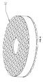
- FIGS. 1-8 Detailed description of the invention will be given below in conjunction with accompanying FIGS. 1-8 .
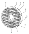
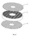
- an infrared device applied to a gas appliance comprises a honeycomb body 10.
- the honeycomb body 10 comprises a metal band and a plurality of holes which are formed by laminating or coiling the metal band.
- the honeycomb body 10 has a first surface A 14 and a second surface B 15 which are opposite to each other, and a lateral surface 16 connecting an edge of the first surface A and an edge of the second surface B.
- a through hole 50 is disposed on the lateral surface of the honeycomb body and penetrates inward through multiple layers of adjacent metal bands, and a metal wire 51 is disposed in the through hole 50 for fixing the metal bands.
- the through hole 50 and the metal wire 51 disposed in the through hole 50 constitute a special fixed structure.
- Conventional infrared honeycomb body is apt to expand and deform due to the frequent alternation between high and low temperatures, which causes the deformation and axial movement of the honeycomb body.
- the arrangement of the special fixed structure can effectively prevent the deformation and axial movement of the metal bands of the honeycomb body.
- the holes are round, oval, semi-circular, or polygonal in shape.
- the hole having the above shapes has better combustion characteristics.
- a central hole 12 having a diameter of between 2 and 300 mm is disposed in the middle of the honeycomb body 10 to operate as an air flow channel.
- the air flow channel allows the fuel gas to mix with the air again to ensure a complete combustion.
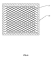
- the central hole 12, the lateral surface 16, or the both are encircled by a metal frame 20 or 30 whereby fixing the honeycomb body.
- At least one end of the metal wire 51 is fixed on the wire band or the metal frame 20 or 30.
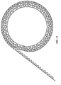
- honeycomb 10 is formed by laminating the metal band, it is not limited to this, the honeycomb can also be formed using other methods, for example, by coiling the metal band.
- an infrared device applied to a gas appliance comprises a honeycomb body 10.
- the honeycomb body 10 comprises a metal band and a plurality of holes or gaps which are formed by laminating or coiling the metal band.
- the honeycomb body 10 has a first surface A 14 and a second surface B 15 which are opposite to each other, and a lateral surface 16 connecting an edge of the first surface A and an edge of the second surface B.
- a part of the metal band on the first surface A and/or the second surface B are embedded, overlapped and engaged with adjacent metal bands to form an embedded member 60.
- the embedded member 60 arranged on part of the first surface A and/or the second surface B can effectively prevent the expansion and deformation due to the frequent alternation between high and low temperatures, thereby preventing the deformation and axial movement of the metal bands of the honeycomb body. Additionally, in contrast to the infrared device in Example 1, the infrared device of this example has a simple process, thereby saving the production costs.
- honeycomb 10 is formed by laminating the metal band, it is not limited to this, the honeycomb can also be formed using other methods, for example, by coiling the metal band.
- a space formed by embedding the metal bands is filled with a metal material 61, and the metal material is fixed on the metal bands by welding.
- the embedded member is formed on some of the metal bands close to the edge of the honeycomb body.When the embedded member is disposed where the protrusion is most likely to occur, fewer embedded members can achieve better deformation resistance effect.
- theembedded member intersects with all the metal bands of the honeycomb body. Such an arrangement of the embedded membersimplifies the manufacturing process of the infrared device.
- the embedded member is Y-shaped, with an outward opening.
- the Y-shaped embedded member can prevent the congestion thereof in the center of the honeycomb body.
- the embedded member 60 is formed and fixed by self-melting and welding of the metal bands.
- theembedded member 60 can be disposed on the first surface A and/or the second surface B. If the embedded member 60 is disposed on the first surface A, upon combustion, the infrared device can display patterns that cannot be displayed during nonuse.
- a central hole 12 having a diameter of between 2 and 300 mm is disposed in the middle of the honeycomb body 10 to operate as an air flow channel, and the central hole 12, the lateral surface 16, or the both are encircled by a metal frame 20 or 30.
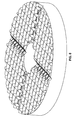
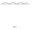
- the metal bands employ a corrugated metal band 13, or an integrated metal band comprising a corrugated metal band 13 and a smooth metal band 11.
- the holes of the resulting honeycomb are regular in shapes, the manufacturing process is simple, and the combustion is complete and uniform.
- FIG. 5 shows the honeycomb body formed by laminating the corrugated metal bands 13.
- FIG. 6 shows the honeycomb body comprising the metal frame.
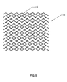
- thefirst surface A14 and/or the second surface B15 of the honeycomb body 10 is covered with a metal mesh 40, and a contact point between the honeycomb body and the metal mesh is fixed by welding.
- the welding of the honeycomb body 10 and the metal mesh 40 enhances the strength of the infrared device, prevents the deformation and axial movement of the metal bands of the honeycomb body due to the frequent alternation between high and low temperatures, and provides a uniform air flow whereby avoiding backfire.
- metal wires for forming the metal mesh have a diameter of between 0.01 and 10 mm, and the meshes of the metal mesh are between 2 and 500 per square inch.
- the metal mesh is formed by coiling and interweaving fine metal fibers irregularly.
- the honeycomb body 10 has a thickness of between 1 and 100 mm.
- the metal bands constituting the honeycomb body 10 have a thickness of between 0.01 and 2 mm.
- the honeycomb body 10 has an opening percentage of between 10 and 95%.
- the honeycomb body 10 is made of iron-chromium alloy, nickel-chromium alloy, or titanium alloy.
- the holes or gaps of the honeycomb body 10 are round, square, or hexagonal in shape.
- a method formanufacturing the infrared device as described in Example 1, comprises the following steps:
- the present honeycomb formed by laminating or coiling the metal bands has a much simple manufacturing process, low manufacturing costs, and high opening percentage.
- a central hole having a diameter of between 2 and 300 mm is disposed in the middle of the honeycomb body to operate as an air flow channel.
- a metal frame is disposed to encircle the central hole and the lateral surface 16whereby fixing the honeycomb body.
- the metal frame is disposed, at least one end of the metal wire is fixed on the wire band or the metal frame.
- the first surface A and/or the second surface B of the honeycomb body is covered with a metal mesh, or the first surface A and/or the second surface B of the honeycomb body is covered with a metal fiber structure, the metal fiber structure is breathable and presents in the form of fiber mesh, fiber felt, woven mesh, or fiber paper, and a contact point thereof is fixed by welding.
- a method for manufacturing the infrared device as described in Example 2 comprises the following steps:
- the method further comprises filling a space formed by embedding the metal bands with a metal material, and fixing the metal material on the metal bands by welding, whereby enhancing the strength of the metal infrared device, and preventing the deformation and axial movement of the metal bands of the honeycomb body due to the frequent alternation between high and low temperatures.
- the method further comprises fixing the embedded metal bands by self-melting and welding of the embedded metal bands, whereby achieving the same welding effect as the metal filling material and saving the material cost.
- the method further comprises disposing a central hole having a diameter of between 2 and 300 mm in the middle of the honeycomb body to operate as an air flow channel.
- the method further comprises disposing metal frames to encircle the central hole and the lateral surface 16, respectively, for fixing the honeycomb body.
- the first surface A14 and/or the second surface B 15 of the honeycomb body is covered with a metal mesh, or the first surface A and/or the second surface B of the honeycomb body is covered with a metal fiber structure, the metal fiber structure is breathable and presents in the form of fiber mesh, fiber felt, woven mesh, or fiber paper, and a contact point thereof is fixed by welding.
- the welding of the honeycomb body and the metal mesh or metal fiber structure can effectively enhance the strength of the infrared device and prevent the detachment of the metal mesh or metal fiber structure.
- step A) is achieved according to one of the following three steps:
- the corrugated metal band prepared in step 1) is in the form of undulation, sinusoidal waveform, sawtooth waveform, U-shaped waveform, or rectangular waveform.
- the metal bands having the above waveforms can form holes having better combustion characteristics.
- the metal bands can be laminated or coiled to yield the honeycomb body having holes with regular openings and desired opening percentage.
Landscapes
- Engineering & Computer Science (AREA)
- Chemical & Material Sciences (AREA)
- Combustion & Propulsion (AREA)
- Mechanical Engineering (AREA)
- General Engineering & Computer Science (AREA)
- Laminated Bodies (AREA)
- Gas Burners (AREA)
- Resistance Heating (AREA)
- Exhaust Gas After Treatment (AREA)
Applications Claiming Priority (3)
| Application Number | Priority Date | Filing Date | Title |
|---|---|---|---|
| CN201110138509 | 2011-05-26 | ||
| CN201110145728.XA CN102798123B (zh) | 2011-05-26 | 2011-06-01 | 一种红外线金属发热体及其制作方法 |
| PCT/CN2012/076128 WO2012159589A1 (zh) | 2011-05-26 | 2012-05-25 | 一种红外线金属发热体及其制作方法 |
Publications (3)
| Publication Number | Publication Date |
|---|---|
| EP2716979A1 true EP2716979A1 (de) | 2014-04-09 |
| EP2716979A4 EP2716979A4 (de) | 2015-07-29 |
| EP2716979B1 EP2716979B1 (de) | 2019-01-09 |
Family
ID=47197337
Family Applications (1)
| Application Number | Title | Priority Date | Filing Date |
|---|---|---|---|
| EP12788740.4A Not-in-force EP2716979B1 (de) | 2011-05-26 | 2012-05-25 | Infrarot-vorrichtung und herstellungsverfahren dafür |
Country Status (10)
| Country | Link |
|---|---|
| US (1) | US9625148B2 (de) |
| EP (1) | EP2716979B1 (de) |
| JP (1) | JP6023798B2 (de) |
| KR (1) | KR20140013065A (de) |
| CN (1) | CN102798123B (de) |
| AU (2) | AU2012261367B2 (de) |
| BR (1) | BR112013029989A2 (de) |
| MX (1) | MX363078B (de) |
| RU (1) | RU2600801C2 (de) |
| WO (1) | WO2012159589A1 (de) |
Cited By (1)
| Publication number | Priority date | Publication date | Assignee | Title |
|---|---|---|---|---|
| EP2655967B1 (de) * | 2010-12-20 | 2017-08-09 | Solaronics S.A. | Gasheizstrahler mit geprägtem schirm |
Families Citing this family (14)
| Publication number | Priority date | Publication date | Assignee | Title |
|---|---|---|---|---|
| WO2015042613A1 (en) * | 2013-09-23 | 2015-03-26 | Christopher A. Wiklof | POROUS FLAME HOLDER FOR LOW NOx COMBUSTION |
| CN103528109B (zh) * | 2013-09-29 | 2015-10-21 | 郑运婷 | 红外线金属蜂窝燃烧板的制造方法 |
| CN105979782B (zh) | 2013-12-16 | 2020-08-18 | 德卢卡烤炉技术有限责任公司 | 用于丝网加热元件和编织成角度的丝网的连续更新系统 |
| US10203108B2 (en) | 2014-08-14 | 2019-02-12 | De Luca Oven Technologies, Llc | Vapor generator including wire mesh heating element |
| CN109297051B (zh) * | 2017-07-24 | 2024-07-16 | 华帝股份有限公司 | 用于红外燃气灶的金属蜂窝发热体 |
| CN109297056B (zh) * | 2017-07-25 | 2023-11-28 | 华帝股份有限公司 | 一种缝隙式燃烧板及其制作方法及应用该燃烧板的燃烧器 |
| CN108716672A (zh) * | 2018-06-08 | 2018-10-30 | 江苏智道工程技术有限公司 | 金属格子燃烧头 |
| CN108826290A (zh) * | 2018-08-06 | 2018-11-16 | 杭州老板电器股份有限公司 | 低排放高效燃烧器 |
| TWI685631B (zh) * | 2018-08-31 | 2020-02-21 | 關隆股份有限公司 | 紅外線產生網 |
| JP2020063868A (ja) * | 2018-10-16 | 2020-04-23 | 東京瓦斯株式会社 | 表面燃焼バーナ |
| CN110160047B (zh) * | 2019-05-24 | 2024-11-01 | 华帝股份有限公司 | 一种管式蜂窝体及燃烧器 |
| CN110307542B (zh) * | 2019-06-25 | 2024-07-09 | 华帝股份有限公司 | 一种鼓风式燃气燃烧器 |
| GB2630723A (en) | 2020-10-07 | 2024-12-04 | Edwards Ltd | Burner Liner |
| CN119468202B (zh) * | 2023-08-11 | 2025-09-26 | 华帝股份有限公司 | 蜂窝体及其制作方法 |
Family Cites Families (48)
| Publication number | Priority date | Publication date | Assignee | Title |
|---|---|---|---|---|
| US1372724A (en) * | 1919-12-26 | 1921-03-29 | Cleveland Gas Burner & Applian | Gaseous-fuel burner |
| US3088271A (en) * | 1961-02-06 | 1963-05-07 | Minnesota Mining & Mfg | Reaction milieu and afterburner incorporating same |
| JPS5019778B1 (de) * | 1966-03-22 | 1975-07-09 | ||
| US3438719A (en) * | 1966-10-19 | 1969-04-15 | Cleaver Brooks Co | Spiral ribbon gas burner |
| US4361620A (en) * | 1979-03-08 | 1982-11-30 | Wing Industries, Inc. | Total energy exchange medium and method of making the same |
| US4348360A (en) * | 1979-11-05 | 1982-09-07 | Minnesota Mining And Manufacturing Company | Catalytic converter for ozone removal in aircraft |
| JPS5866707A (ja) * | 1981-10-16 | 1983-04-21 | Matsushita Electric Ind Co Ltd | バ−ナ |
| NL8304041A (nl) * | 1983-11-24 | 1985-06-17 | Remeha Fabrieken Bv | Verwarmingsketel met verticale branderbuis. |
| US4527538A (en) * | 1984-05-10 | 1985-07-09 | Dennis Caferro | Self-contained oven |
| JPS62142915A (ja) * | 1985-12-17 | 1987-06-26 | Matsushita Electric Ind Co Ltd | 赤外線バ−ナ |
| EP0248629B1 (de) * | 1986-06-04 | 1992-08-12 | Ambi-Rad Limited | Raumheizgerät |
| US4793136A (en) * | 1987-08-26 | 1988-12-27 | W. R. Grace & Co. | Reinforced metallic honeycomb structure |
| JPH02118308A (ja) * | 1988-10-26 | 1990-05-02 | Osaka Gas Co Ltd | 表面燃焼バーナ |
| JPH02126011A (ja) * | 1988-11-04 | 1990-05-15 | Osaka Gas Co Ltd | 表面燃焼バーナ |
| US6288008B1 (en) * | 1991-07-04 | 2001-09-11 | Matsumoto Kokan Co., Ltd. | Metallic catalyst support and production method thereof |
| JP2659504B2 (ja) * | 1991-12-26 | 1997-09-30 | 大阪瓦斯株式会社 | 触媒燃焼装置 |
| NL9200460A (nl) * | 1992-03-12 | 1993-10-01 | Flameco Eclipse Bv | Gasbrander, menginrichting voor verbrandingslucht en brandbaar gas, ketelinstallatie en verwarminginstallatie, voorzien van een dergelijke gasbrander en menginrichting. |
| JP3336035B2 (ja) * | 1992-04-27 | 2002-10-21 | 臼井国際産業株式会社 | 金属製ハニカム担体 |
| BE1005992A4 (nl) * | 1992-06-10 | 1994-04-12 | Bekaert Sa Nv | Poreus membraan voor oppervlakte stralingsbrander. |
| JPH07171413A (ja) * | 1993-12-17 | 1995-07-11 | Usui Internatl Ind Co Ltd | メタル担体 |
| JP3339958B2 (ja) * | 1994-03-10 | 2002-10-28 | 日信化学工業株式会社 | 磁気記録媒体 |
| JPH07280220A (ja) * | 1994-04-01 | 1995-10-27 | Chugai Ro Co Ltd | ノズルミックスバーナにおける燃焼方法及びノズルミックスバーナ |
| KR100374764B1 (ko) * | 1995-12-13 | 2003-04-18 | 케미라 메탈카트 오와이 | 화학반응기내의난류발생기 |
| JP3532336B2 (ja) * | 1995-12-19 | 2004-05-31 | オパーツ株式会社 | ガスバーナ用火口 |
| US5737839A (en) * | 1995-12-22 | 1998-04-14 | Engelhard Corporation | Assembly and method for making catalytic converter structures |
| JP3631567B2 (ja) * | 1996-10-02 | 2005-03-23 | 大阪瓦斯株式会社 | ラインバーナ |
| JP3712838B2 (ja) * | 1997-07-02 | 2005-11-02 | 田中貴金属工業株式会社 | 燃焼触媒保持装置 |
| DE19922355A1 (de) * | 1999-05-14 | 2000-11-23 | Helmut Swars | Katalysatorträgerkörper |
| DE19922358C1 (de) * | 1999-05-14 | 2001-01-25 | Helmut Swars | Wabenkörper |
| DE19922356C2 (de) * | 1999-05-14 | 2001-06-13 | Helmut Swars | Wabenkörper |
| DE19922357C1 (de) * | 1999-05-14 | 2000-11-09 | Helmut Swars | Wabenkörper und Verfahren zu dessen Herstellung |
| JP2001065815A (ja) * | 1999-08-31 | 2001-03-16 | Denso Corp | 燃焼装置 |
| JP3413141B2 (ja) * | 1999-11-16 | 2003-06-03 | 新日本製鐵株式会社 | メタルハニカム体、熱交換器用蓄熱体、蓄熱式バーナー及びメタル担体 |
| DE10114903A1 (de) * | 2001-03-26 | 2002-10-17 | Invent Gmbh Entwicklung Neuer Technologien | Brenner für ein Gas/Luft-Gemisch |
| DE10119035A1 (de) * | 2001-04-18 | 2002-10-24 | Alstom Switzerland Ltd | Katalytisch arbeitender Brenner |
| JP3912295B2 (ja) * | 2003-02-21 | 2007-05-09 | 株式会社デンソー | 触媒反応式加熱装置 |
| FI118418B (fi) * | 2003-04-17 | 2007-11-15 | Ecocat Oy | Alumiinioksidipohjainen katalyytti poistekaasujen puhdistukseen |
| JP4360273B2 (ja) * | 2004-06-02 | 2009-11-11 | 株式会社Ihi | 触媒燃焼器 |
| US7655194B2 (en) * | 2005-01-18 | 2010-02-02 | Dcl International Inc. | Catalyst substrate support |
| CN100338394C (zh) * | 2005-06-23 | 2007-09-19 | 罗添翼 | 用在燃气用具上的红外线金属蜂窝体燃烧器及其制作方法 |
| US7931240B2 (en) * | 2006-08-11 | 2011-04-26 | Techno-Sciences, Inc. | Cellular support structures used for controlled actuation of fluid contact surfaces |
| CN101082428A (zh) * | 2007-01-19 | 2007-12-05 | 罗添翼 | 用在燃气炉上有红外辐射功能的燃烧器复合发热体 |
| CN201170553Y (zh) * | 2007-11-28 | 2008-12-24 | 李长江 | 一种复合型红外线燃烧器 |
| CN101225958B (zh) * | 2008-01-16 | 2011-05-04 | 罗添翼 | 用在燃气用具和燃气设备燃烧器上的高效发热体 |
| WO2010003904A1 (en) * | 2008-07-08 | 2010-01-14 | Nv Bekaert Sa | Improved radiant burner |
| CN101363639B (zh) * | 2008-09-27 | 2010-06-02 | 胡广兵 | 金属燃烧板 |
| DE102009028624A1 (de) * | 2009-08-18 | 2011-02-24 | Sandvik Intellectual Property Ab | Strahlungsbrenner |
| JP5112405B2 (ja) * | 2009-09-15 | 2013-01-09 | 内外施設工業株式会社 | バーナー、ガス焼成装置 |
-
2011
- 2011-06-01 CN CN201110145728.XA patent/CN102798123B/zh active Active
-
2012
- 2012-05-25 KR KR1020137032308A patent/KR20140013065A/ko not_active Ceased
- 2012-05-25 EP EP12788740.4A patent/EP2716979B1/de not_active Not-in-force
- 2012-05-25 RU RU2013156777/03A patent/RU2600801C2/ru active
- 2012-05-25 WO PCT/CN2012/076128 patent/WO2012159589A1/zh not_active Ceased
- 2012-05-25 JP JP2014511725A patent/JP6023798B2/ja not_active Expired - Fee Related
- 2012-05-25 BR BR112013029989A patent/BR112013029989A2/pt not_active Application Discontinuation
- 2012-05-25 MX MX2013013898A patent/MX363078B/es unknown
- 2012-05-25 AU AU2012261367A patent/AU2012261367B2/en not_active Ceased
-
2013
- 2013-11-26 US US14/089,844 patent/US9625148B2/en not_active Expired - Fee Related
-
2016
- 2016-11-21 AU AU2016262643A patent/AU2016262643B2/en not_active Ceased
Cited By (1)
| Publication number | Priority date | Publication date | Assignee | Title |
|---|---|---|---|---|
| EP2655967B1 (de) * | 2010-12-20 | 2017-08-09 | Solaronics S.A. | Gasheizstrahler mit geprägtem schirm |
Also Published As
| Publication number | Publication date |
|---|---|
| RU2600801C2 (ru) | 2016-10-27 |
| AU2012261367B2 (en) | 2016-10-13 |
| MX2013013898A (es) | 2014-01-24 |
| EP2716979B1 (de) | 2019-01-09 |
| CN102798123A (zh) | 2012-11-28 |
| KR20140013065A (ko) | 2014-02-04 |
| MX363078B (es) | 2019-03-07 |
| JP2014517244A (ja) | 2014-07-17 |
| CN102798123B (zh) | 2016-05-04 |
| US20140080079A1 (en) | 2014-03-20 |
| BR112013029989A2 (pt) | 2017-12-05 |
| EP2716979A4 (de) | 2015-07-29 |
| AU2016262643B2 (en) | 2018-07-19 |
| WO2012159589A1 (zh) | 2012-11-29 |
| JP6023798B2 (ja) | 2016-11-09 |
| RU2013156777A (ru) | 2015-07-10 |
| AU2016262643A1 (en) | 2016-12-08 |
| AU2012261367A1 (en) | 2014-01-16 |
| US9625148B2 (en) | 2017-04-18 |
Similar Documents
| Publication | Publication Date | Title |
|---|---|---|
| EP2716979A1 (de) | Infrarot-metallerhitzungskörper und herstellungsverfahren dafür | |
| CN105757669B (zh) | 燃气灶燃烧面板及燃气灶 | |
| JPH0751986B2 (ja) | ガスケツト | |
| WO1999048830A1 (fr) | Panneau de verre | |
| CN204100318U (zh) | 一种低辐射电磁炉 | |
| EP3337291A1 (de) | Heizeinrichtung, kochgerät mit einer heizeinrichtung und verfahren zur herstellung eines heizelements | |
| US20170284293A1 (en) | Heat shield and part shielded with such a heat shield | |
| CN202303581U (zh) | 网板结合型红外线金属蜂窝发热体 | |
| CN209026821U (zh) | 红外线燃烧板 | |
| CN207214045U (zh) | 一种红外金属发热体 | |
| CN206251375U (zh) | 线圈盘及电磁烹饪器具 | |
| CN202216249U (zh) | 燃气红外线燃烧器所用的金属复合材料发热板 | |
| CN201947486U (zh) | 一种电磁炉线圈盘装置 | |
| CN212841570U (zh) | 一种红外线金属蜂窝体和红外线金属燃烧器 | |
| CN110207121B (zh) | 红外线燃烧板及该红外线燃烧板的制作方法 | |
| CN211011560U (zh) | 一种自带固定结构的辐射燃烧板 | |
| CN201894562U (zh) | 复合底锅 | |
| CN206118078U (zh) | 电磁线圈盘组件及电磁加热烹饪装置 | |
| CN202561756U (zh) | 用在燃气用具上具有同体异目功能的金属蜂窝发热体 | |
| CN206118082U (zh) | 线圈盘组件及电磁加热烹饪装置 | |
| JP2002372381A (ja) | 加熱炉及びその発熱体の製造方法 | |
| CN103162293B (zh) | 组合式金属发热体红外炉盘 | |
| CN214949022U (zh) | 一种绕制成型的炉头火孔组件 | |
| CN210532456U (zh) | 嵌入式燃气灶玻璃面板的固定结构 | |
| CN213786923U (zh) | 一种新型发热盘 |
Legal Events
| Date | Code | Title | Description |
|---|---|---|---|
| PUAI | Public reference made under article 153(3) epc to a published international application that has entered the european phase |
Free format text: ORIGINAL CODE: 0009012 |
|
| 17P | Request for examination filed |
Effective date: 20131226 |
|
| AK | Designated contracting states |
Kind code of ref document: A1 Designated state(s): AL AT BE BG CH CY CZ DE DK EE ES FI FR GB GR HR HU IE IS IT LI LT LU LV MC MK MT NL NO PL PT RO RS SE SI SK SM TR |
|
| DAX | Request for extension of the european patent (deleted) | ||
| RIC1 | Information provided on ipc code assigned before grant |
Ipc: F24C 3/04 20060101ALI20150618BHEP Ipc: F24C 15/24 20060101AFI20150618BHEP Ipc: F23D 14/02 20060101ALN20150618BHEP Ipc: F23D 14/14 20060101ALI20150618BHEP |
|
| RA4 | Supplementary search report drawn up and despatched (corrected) |
Effective date: 20150625 |
|
| GRAP | Despatch of communication of intention to grant a patent |
Free format text: ORIGINAL CODE: EPIDOSNIGR1 |
|
| STAA | Information on the status of an ep patent application or granted ep patent |
Free format text: STATUS: GRANT OF PATENT IS INTENDED |
|
| RIC1 | Information provided on ipc code assigned before grant |
Ipc: F23D 14/02 20060101ALN20180724BHEP Ipc: F24C 15/24 20060101AFI20180724BHEP Ipc: F23D 14/14 20060101ALI20180724BHEP Ipc: F24C 3/04 20060101ALI20180724BHEP |
|
| INTG | Intention to grant announced |
Effective date: 20180817 |
|
| GRAS | Grant fee paid |
Free format text: ORIGINAL CODE: EPIDOSNIGR3 |
|
| GRAA | (expected) grant |
Free format text: ORIGINAL CODE: 0009210 |
|
| STAA | Information on the status of an ep patent application or granted ep patent |
Free format text: STATUS: THE PATENT HAS BEEN GRANTED |
|
| AK | Designated contracting states |
Kind code of ref document: B1 Designated state(s): AL AT BE BG CH CY CZ DE DK EE ES FI FR GB GR HR HU IE IS IT LI LT LU LV MC MK MT NL NO PL PT RO RS SE SI SK SM TR |
|
| REG | Reference to a national code |
Ref country code: GB Ref legal event code: FG4D |
|
| REG | Reference to a national code |
Ref country code: CH Ref legal event code: EP Ref country code: AT Ref legal event code: REF Ref document number: 1087796 Country of ref document: AT Kind code of ref document: T Effective date: 20190115 |
|
| REG | Reference to a national code |
Ref country code: DE Ref legal event code: R096 Ref document number: 602012055757 Country of ref document: DE |
|
| REG | Reference to a national code |
Ref country code: IE Ref legal event code: FG4D |
|
| REG | Reference to a national code |
Ref country code: NL Ref legal event code: MP Effective date: 20190109 |
|
| REG | Reference to a national code |
Ref country code: LT Ref legal event code: MG4D |
|
| PG25 | Lapsed in a contracting state [announced via postgrant information from national office to epo] |
Ref country code: NL Free format text: LAPSE BECAUSE OF FAILURE TO SUBMIT A TRANSLATION OF THE DESCRIPTION OR TO PAY THE FEE WITHIN THE PRESCRIBED TIME-LIMIT Effective date: 20190109 |
|
| REG | Reference to a national code |
Ref country code: AT Ref legal event code: MK05 Ref document number: 1087796 Country of ref document: AT Kind code of ref document: T Effective date: 20190109 |
|
| PG25 | Lapsed in a contracting state [announced via postgrant information from national office to epo] |
Ref country code: SE Free format text: LAPSE BECAUSE OF FAILURE TO SUBMIT A TRANSLATION OF THE DESCRIPTION OR TO PAY THE FEE WITHIN THE PRESCRIBED TIME-LIMIT Effective date: 20190109 Ref country code: ES Free format text: LAPSE BECAUSE OF FAILURE TO SUBMIT A TRANSLATION OF THE DESCRIPTION OR TO PAY THE FEE WITHIN THE PRESCRIBED TIME-LIMIT Effective date: 20190109 Ref country code: LT Free format text: LAPSE BECAUSE OF FAILURE TO SUBMIT A TRANSLATION OF THE DESCRIPTION OR TO PAY THE FEE WITHIN THE PRESCRIBED TIME-LIMIT Effective date: 20190109 Ref country code: FI Free format text: LAPSE BECAUSE OF FAILURE TO SUBMIT A TRANSLATION OF THE DESCRIPTION OR TO PAY THE FEE WITHIN THE PRESCRIBED TIME-LIMIT Effective date: 20190109 Ref country code: NO Free format text: LAPSE BECAUSE OF FAILURE TO SUBMIT A TRANSLATION OF THE DESCRIPTION OR TO PAY THE FEE WITHIN THE PRESCRIBED TIME-LIMIT Effective date: 20190409 Ref country code: PT Free format text: LAPSE BECAUSE OF FAILURE TO SUBMIT A TRANSLATION OF THE DESCRIPTION OR TO PAY THE FEE WITHIN THE PRESCRIBED TIME-LIMIT Effective date: 20190509 Ref country code: PL Free format text: LAPSE BECAUSE OF FAILURE TO SUBMIT A TRANSLATION OF THE DESCRIPTION OR TO PAY THE FEE WITHIN THE PRESCRIBED TIME-LIMIT Effective date: 20190109 |
|
| PG25 | Lapsed in a contracting state [announced via postgrant information from national office to epo] |
Ref country code: LV Free format text: LAPSE BECAUSE OF FAILURE TO SUBMIT A TRANSLATION OF THE DESCRIPTION OR TO PAY THE FEE WITHIN THE PRESCRIBED TIME-LIMIT Effective date: 20190109 Ref country code: IS Free format text: LAPSE BECAUSE OF FAILURE TO SUBMIT A TRANSLATION OF THE DESCRIPTION OR TO PAY THE FEE WITHIN THE PRESCRIBED TIME-LIMIT Effective date: 20190509 Ref country code: HR Free format text: LAPSE BECAUSE OF FAILURE TO SUBMIT A TRANSLATION OF THE DESCRIPTION OR TO PAY THE FEE WITHIN THE PRESCRIBED TIME-LIMIT Effective date: 20190109 Ref country code: RS Free format text: LAPSE BECAUSE OF FAILURE TO SUBMIT A TRANSLATION OF THE DESCRIPTION OR TO PAY THE FEE WITHIN THE PRESCRIBED TIME-LIMIT Effective date: 20190109 Ref country code: BG Free format text: LAPSE BECAUSE OF FAILURE TO SUBMIT A TRANSLATION OF THE DESCRIPTION OR TO PAY THE FEE WITHIN THE PRESCRIBED TIME-LIMIT Effective date: 20190409 Ref country code: GR Free format text: LAPSE BECAUSE OF FAILURE TO SUBMIT A TRANSLATION OF THE DESCRIPTION OR TO PAY THE FEE WITHIN THE PRESCRIBED TIME-LIMIT Effective date: 20190410 |
|
| REG | Reference to a national code |
Ref country code: DE Ref legal event code: R097 Ref document number: 602012055757 Country of ref document: DE |
|
| PG25 | Lapsed in a contracting state [announced via postgrant information from national office to epo] |
Ref country code: AL Free format text: LAPSE BECAUSE OF FAILURE TO SUBMIT A TRANSLATION OF THE DESCRIPTION OR TO PAY THE FEE WITHIN THE PRESCRIBED TIME-LIMIT Effective date: 20190109 Ref country code: RO Free format text: LAPSE BECAUSE OF FAILURE TO SUBMIT A TRANSLATION OF THE DESCRIPTION OR TO PAY THE FEE WITHIN THE PRESCRIBED TIME-LIMIT Effective date: 20190109 Ref country code: CZ Free format text: LAPSE BECAUSE OF FAILURE TO SUBMIT A TRANSLATION OF THE DESCRIPTION OR TO PAY THE FEE WITHIN THE PRESCRIBED TIME-LIMIT Effective date: 20190109 Ref country code: EE Free format text: LAPSE BECAUSE OF FAILURE TO SUBMIT A TRANSLATION OF THE DESCRIPTION OR TO PAY THE FEE WITHIN THE PRESCRIBED TIME-LIMIT Effective date: 20190109 Ref country code: AT Free format text: LAPSE BECAUSE OF FAILURE TO SUBMIT A TRANSLATION OF THE DESCRIPTION OR TO PAY THE FEE WITHIN THE PRESCRIBED TIME-LIMIT Effective date: 20190109 Ref country code: SK Free format text: LAPSE BECAUSE OF FAILURE TO SUBMIT A TRANSLATION OF THE DESCRIPTION OR TO PAY THE FEE WITHIN THE PRESCRIBED TIME-LIMIT Effective date: 20190109 Ref country code: IT Free format text: LAPSE BECAUSE OF FAILURE TO SUBMIT A TRANSLATION OF THE DESCRIPTION OR TO PAY THE FEE WITHIN THE PRESCRIBED TIME-LIMIT Effective date: 20190109 Ref country code: DK Free format text: LAPSE BECAUSE OF FAILURE TO SUBMIT A TRANSLATION OF THE DESCRIPTION OR TO PAY THE FEE WITHIN THE PRESCRIBED TIME-LIMIT Effective date: 20190109 |
|
| PLBE | No opposition filed within time limit |
Free format text: ORIGINAL CODE: 0009261 |
|
| STAA | Information on the status of an ep patent application or granted ep patent |
Free format text: STATUS: NO OPPOSITION FILED WITHIN TIME LIMIT |
|
| PG25 | Lapsed in a contracting state [announced via postgrant information from national office to epo] |
Ref country code: SM Free format text: LAPSE BECAUSE OF FAILURE TO SUBMIT A TRANSLATION OF THE DESCRIPTION OR TO PAY THE FEE WITHIN THE PRESCRIBED TIME-LIMIT Effective date: 20190109 |
|
| 26N | No opposition filed |
Effective date: 20191010 |
|
| REG | Reference to a national code |
Ref country code: CH Ref legal event code: PL |
|
| GBPC | Gb: european patent ceased through non-payment of renewal fee |
Effective date: 20190525 |
|
| PG25 | Lapsed in a contracting state [announced via postgrant information from national office to epo] |
Ref country code: MC Free format text: LAPSE BECAUSE OF FAILURE TO SUBMIT A TRANSLATION OF THE DESCRIPTION OR TO PAY THE FEE WITHIN THE PRESCRIBED TIME-LIMIT Effective date: 20190109 Ref country code: CH Free format text: LAPSE BECAUSE OF NON-PAYMENT OF DUE FEES Effective date: 20190531 Ref country code: LI Free format text: LAPSE BECAUSE OF NON-PAYMENT OF DUE FEES Effective date: 20190531 |
|
| REG | Reference to a national code |
Ref country code: BE Ref legal event code: MM Effective date: 20190531 |
|
| PG25 | Lapsed in a contracting state [announced via postgrant information from national office to epo] |
Ref country code: SI Free format text: LAPSE BECAUSE OF FAILURE TO SUBMIT A TRANSLATION OF THE DESCRIPTION OR TO PAY THE FEE WITHIN THE PRESCRIBED TIME-LIMIT Effective date: 20190109 Ref country code: LU Free format text: LAPSE BECAUSE OF NON-PAYMENT OF DUE FEES Effective date: 20190525 |
|
| PG25 | Lapsed in a contracting state [announced via postgrant information from national office to epo] |
Ref country code: TR Free format text: LAPSE BECAUSE OF FAILURE TO SUBMIT A TRANSLATION OF THE DESCRIPTION OR TO PAY THE FEE WITHIN THE PRESCRIBED TIME-LIMIT Effective date: 20190109 |
|
| PG25 | Lapsed in a contracting state [announced via postgrant information from national office to epo] |
Ref country code: GB Free format text: LAPSE BECAUSE OF NON-PAYMENT OF DUE FEES Effective date: 20190525 Ref country code: IE Free format text: LAPSE BECAUSE OF NON-PAYMENT OF DUE FEES Effective date: 20190525 |
|
| PG25 | Lapsed in a contracting state [announced via postgrant information from national office to epo] |
Ref country code: BE Free format text: LAPSE BECAUSE OF NON-PAYMENT OF DUE FEES Effective date: 20190531 |
|
| PG25 | Lapsed in a contracting state [announced via postgrant information from national office to epo] |
Ref country code: FR Free format text: LAPSE BECAUSE OF NON-PAYMENT OF DUE FEES Effective date: 20190531 |
|
| PG25 | Lapsed in a contracting state [announced via postgrant information from national office to epo] |
Ref country code: CY Free format text: LAPSE BECAUSE OF FAILURE TO SUBMIT A TRANSLATION OF THE DESCRIPTION OR TO PAY THE FEE WITHIN THE PRESCRIBED TIME-LIMIT Effective date: 20190109 |
|
| PG25 | Lapsed in a contracting state [announced via postgrant information from national office to epo] |
Ref country code: MT Free format text: LAPSE BECAUSE OF FAILURE TO SUBMIT A TRANSLATION OF THE DESCRIPTION OR TO PAY THE FEE WITHIN THE PRESCRIBED TIME-LIMIT Effective date: 20190109 Ref country code: HU Free format text: LAPSE BECAUSE OF FAILURE TO SUBMIT A TRANSLATION OF THE DESCRIPTION OR TO PAY THE FEE WITHIN THE PRESCRIBED TIME-LIMIT; INVALID AB INITIO Effective date: 20120525 |
|
| PGFP | Annual fee paid to national office [announced via postgrant information from national office to epo] |
Ref country code: DE Payment date: 20210426 Year of fee payment: 10 |
|
| PG25 | Lapsed in a contracting state [announced via postgrant information from national office to epo] |
Ref country code: MK Free format text: LAPSE BECAUSE OF FAILURE TO SUBMIT A TRANSLATION OF THE DESCRIPTION OR TO PAY THE FEE WITHIN THE PRESCRIBED TIME-LIMIT Effective date: 20190109 |
|
| REG | Reference to a national code |
Ref country code: DE Ref legal event code: R119 Ref document number: 602012055757 Country of ref document: DE |
|
| PG25 | Lapsed in a contracting state [announced via postgrant information from national office to epo] |
Ref country code: DE Free format text: LAPSE BECAUSE OF NON-PAYMENT OF DUE FEES Effective date: 20221201 |