EP2716980A2 - Système de distribution par conduites - Google Patents
Système de distribution par conduites Download PDFInfo
- Publication number
- EP2716980A2 EP2716980A2 EP13187146.9A EP13187146A EP2716980A2 EP 2716980 A2 EP2716980 A2 EP 2716980A2 EP 13187146 A EP13187146 A EP 13187146A EP 2716980 A2 EP2716980 A2 EP 2716980A2
- Authority
- EP
- European Patent Office
- Prior art keywords
- pipe
- main
- main pipe
- tube
- functional unit
- Prior art date
- Legal status (The legal status is an assumption and is not a legal conclusion. Google has not performed a legal analysis and makes no representation as to the accuracy of the status listed.)
- Granted
Links
Images


Classifications
-
- F—MECHANICAL ENGINEERING; LIGHTING; HEATING; WEAPONS; BLASTING
- F24—HEATING; RANGES; VENTILATING
- F24D—DOMESTIC- OR SPACE-HEATING SYSTEMS, e.g. CENTRAL HEATING SYSTEMS; DOMESTIC HOT-WATER SUPPLY SYSTEMS; ELEMENTS OR COMPONENTS THEREFOR
- F24D3/00—Hot-water central heating systems
- F24D3/10—Feed-line arrangements, e.g. providing for heat-accumulator tanks, expansion tanks ; Hydraulic components of a central heating system
- F24D3/1058—Feed-line arrangements, e.g. providing for heat-accumulator tanks, expansion tanks ; Hydraulic components of a central heating system disposition of pipes and pipe connections
- F24D3/1066—Distributors for heating liquids
-
- F—MECHANICAL ENGINEERING; LIGHTING; HEATING; WEAPONS; BLASTING
- F16—ENGINEERING ELEMENTS AND UNITS; GENERAL MEASURES FOR PRODUCING AND MAINTAINING EFFECTIVE FUNCTIONING OF MACHINES OR INSTALLATIONS; THERMAL INSULATION IN GENERAL
- F16L—PIPES; JOINTS OR FITTINGS FOR PIPES; SUPPORTS FOR PIPES, CABLES OR PROTECTIVE TUBING; MEANS FOR THERMAL INSULATION IN GENERAL
- F16L41/00—Branching pipes; Joining pipes to walls
- F16L41/02—Branch units, e.g. made in one piece, welded, riveted
- F16L41/03—Branch units, e.g. made in one piece, welded, riveted comprising junction pieces for four or more pipe members
-
- F—MECHANICAL ENGINEERING; LIGHTING; HEATING; WEAPONS; BLASTING
- F24—HEATING; RANGES; VENTILATING
- F24D—DOMESTIC- OR SPACE-HEATING SYSTEMS, e.g. CENTRAL HEATING SYSTEMS; DOMESTIC HOT-WATER SUPPLY SYSTEMS; ELEMENTS OR COMPONENTS THEREFOR
- F24D2220/00—Components of central heating installations excluding heat sources
- F24D2220/02—Fluid distribution means
Definitions
- the invention relates to a pipe distributor system according to the preamble of claim 1 and to a pipe distributor system according to the preamble of claim 2. Furthermore, the invention relates to a method for producing a thread on parts of the pipe distributor system according to the preamble of claim 12.
- Piping systems are known from the prior art, in which several outlets branch off from a main pipe. These pipe distribution systems are often called in professional circles also Banknikverteiler.
- a heating circuit distributor is used to connect radiators or to connect floor or wall heating systems to one or more main lines. These piping systems generally have a main pipe for the feed and a main pipe for the return. For distribution, monitoring, control and regulation of the partial flows (partial fluid flows), connection elements, flow indicators, valves and thermostats are assigned to the outlets of the main pipe. At the respective connection elements, the respective continuing or returning line of the relevant sub-heating circuit or sub-cooling circuit is connected.
- the heating circuit distributor is used for the distribution of the mass flow from the main / riser from the boiler used for the individual radiators / radiators.
- the central distribution enables a star-shaped connection of the radiators.
- a modified heating circuit distributor is also used for the distribution and balancing (DIN EN 1264-4 "Hydraulic balancing") of the mass flow of individual low-temperature heating circuits in floor or wall heating systems.
- These connection elements, flow indicators, valves and thermostats are referred to below as a functional unit.
- These functional units act, for example, in such a way that, for example, a part of a partial element of the valve - for example a valve plate - acts on a surface of a disposed at the relevant outlet further sub-element of the valve, whereby the flow of the fluid (usually water) influenced or measured becomes.
- the corresponding surface is effectively a valve seat.
- the valve seat or the partial element with the valve seat is accommodated in a connection element arranged at the outlet in question or together with the connection element forms a partial element.
- connection elements and the flow indicators, valves and thermostats are screwed into the main pipe and sealed or glued or soldered, such as in a hot water distributor after the DE 10 2007 010 116 A1 .
- necklaces In order to be able to screw in, glue or solder the functional units, so-called necklaces must first be attached to the main pipe, which may be directed outwards or inwards at the outlets that partially open the main pipe, and it must also, if a screw connection is selected for the assembly, threads are cut or rolled in or on these necklaces.
- the relevant connection elements usually sections of their housing must also be threaded and the outlet must also be provided with a seal, usually an O-ring or sealant or adhesive, so that overall high production costs and assembly costs arise.
- the relevant contact surfaces are to be prepared on the part of the functional unit and the main pipe according to the selected joining method, which requires at least a careful cleaning and thus a further time in the assembly.
- this object is achieved with a manifold system with the features of claim 1 and with a manifold system with the features of claim 2; Claims 2 to 11 disclose design variants of the manifold system.
- a method with provided the features of claim 12; Claims 13 to 15 disclose design variants of the method.
- the invention relates to a piping system for a fluid flow with at least one central main pipe and at least one functional unit for emptying and filling the system or for shutting off, opening or regulating a partial volume flow, wherein the functional unit consists of at least a first and a second sub-element and the Main axis of the main pipe are arranged substantially at right angles and aligned with each other, and wherein the main pipe in the region of the functional units has widenings with at least two mutually parallel joining surfaces.
- the functional unit consists of at least a first and a second sub-element and the Main axis of the main pipe are arranged substantially at right angles and aligned with each other, and wherein the main pipe in the region of the functional units has widenings with at least two mutually parallel joining surfaces.
- An alternative of the invention is a pipe distributor system for a fluid flow with at least one central main pipe and at least one functional unit for draining and filling the system or for shutting off, opening or regulating a partial volume flow, wherein the functional unit consists of at least a first and a second sub-element and to the main axis of the main pipe substantially the main pipe in the region of the functional units has widenings with at least two joining surfaces arranged parallel to one another, in which the main pipe is substantially flat and designed at least in the joining region of the second partial elements such that no necking is formed there.
- a manifold system for a fluid flow ie, that in the said joining region on the main pipe no outlets are present, the flow behavior of the provided in the main pipe and from this through the outlets into partial streams distributed fluid (heat or refrigerant ) less disturbed, so that in particular the regulation of the mass flows (hydraulic balancing) trouble-free, especially sensitive, can be done.
- the outer dimensions of a pipe distribution system can be kept smaller due to the absence of the necking, in particular of necklaces projecting outwards on the main pipe.
- Another advantage is that unintentional and unauthorized loosening of components of the manifold system is prevented by the fixed arrangement of at least partial elements of the functional units on the main pipe.
- the manufacturing and assembly costs can be reduced, in particular the installation costs on site during installation of the pipe distribution systems in the heating system or cooling system, in particular a building, for example, a floor heating or wall heating.
- the assembly is on site simplified, which is particularly advantageous for home improvement but also installation companies.
- At least one subelement of the functional units is fused to the main pipe (1), preferably by welding, in particular by laser welding.
- the second sub-element is a special connection element for a partial volume flow and the associated line.
- the special versions are mentioned later in the description.
- the functional unit in conjunction with the second sub-element - ie the connection element - a valve or a flow indicator or a thermostat.
- At least one housing part of a functional unit is captively and tightly connected to the main pipe, preferably a first sub-element, in particular the sub-element of a functional unit having actuators.
- the actuators are the spindle with a valve disk or, in the case of a flow indicator, the measuring spindle or a regulating sleeve.
- the pipe distribution system consists of at least one main pipe for an inlet and at least one main pipe for the return.
- the fluid is usually water.
- the functional unit is formed in the form of a valve with a valve seat
- this valve seat is formed by at least one region of the main pipe.
- the valve seat is raised relative to the inner surface of the main pipe and directed towards the longitudinal axis of the main pipe.
- the valve seat is an annular wall / bead, wherein the wall is arranged in the region of the edge of the respectively provided opening of the main pipe.
- the bead is formed at the edge region of the respective opening, preferably by deformation.
- the invention also relates to a method for producing a thread for a manifold system, in particular for a manifold according to one of the device claims, in which according to the invention, a pipe end, preferably the tube end of a connection element, is flanged so that the flanged portion of the tube like a second, outer layer on the surface of the output tube comes to rest and in or on this outer layer is threaded.
- a thread is produced at least at one end of the main pipe according to the aforementioned method steps.
- the thread is rolled into the surface.
- the inventor has recognized that, despite the small distances between the main pipe and the outlets and between the outlets, it is possible to fuse them with the main pipe by means of a thermal bonding method, without causing damage to individual components of the components by heat. As a result, the outlets are captive and at the same time tight. This has the further advantage that with one operation the outlets or the components of the system can be mounted. The manufacturing costs and assembly costs are lower. An exchange of functional units and their components or outlets against those with lower quality or lower performance or lower life is no longer possible after the production of a manifold system according to the invention. Warranties on a manifold system and claims arising from these warranties are much easier to control in a piping system according to the invention and unauthorized persons are more clearly detectable than can be done with prior art piping systems.
- FIG. 1a In the FIG. 1a is a main pipe 1 to see, which has a plurality of valves 3 for controlling a fluid at the top.
- ports 15 At the bottom of the main pipe 1 ports 15 are arranged, which are axially opposite the valves 3.
- the main pipe 1 can be connected by means of a union nut 13 with other - not shown here pipes.
- the end of the main pipe 1 is provided with a sealing plug 8.
- An emptying element 6 for filling or emptying the manifold system is mounted on the underside of the main pipe 1. If the system is filled, a stopcock, not shown here, is closed at the emptying element 6.
- a closure cap 17 prevents fouling of the connection thread on the Emptying element 6.
- a venting element 7 Above the emptying element 6, a venting element 7 is arranged, which is often designed as fully automatic venting.
- the main tubes 1 are provided with widenings, so that the per se round main tubes 1 above and below each have a plate-shaped mounting surface - a joining surface for functional units - receive.
- the widenings are the regions of the original main tube 1 which, at least in the median plane of the widening transverse to the main axis 20, finally represent a substantially square cross section of this tube, see in FIGS FIGS. 2a and 2b , Since the expansions are not clearly represented by reference numerals, a reference number has been omitted here.
- connection elements 15 and 18 are fused to the main pipe 1.
- the first, arranged above the main pipe 1 sub-elements of the functional units are fused to the main pipe 1, preferably portions of the housing.
- heat-sensitive components (screw caps, collars, etc.) of the first (upper) sub-elements are attached to the functional unit only after merging with the main pipe 1.
- the fusion can be done by means of different welding techniques. This requires that both the main pipe 1 and the sub-elements one have similar material.
- a preferred welding technique is laser welding.
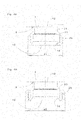
- FIGS. 2a and 2b you can see both the expanded, quasi-square and at the same time the original circular cross-section of the main pipe 1.
- the light edges 21 By the expansion of the pipe cross-section at this point, the light edges 21.
- a valve plate 10 of the valve 3 is at a defined distance from an opening 12 of the main pipe 1 and thus generates a defined flow of the partial volume flow of the fluid.
- the connection 19 is not connected by means of a necking - similar to the upper part of the valve element 3 - with the main pipe 1, but is welded from the outside to the surface of the main pipe 1 by means of a weld 9.
- valve element 3 is screwed by means of a thread in the main pipe 1 here.
- this upper subelement can also be fused to the main tube 1.
- all easily detachable parts must be heat resistant. That is, the valve cap 16, which is usually made of plastic, may be attached only after cooling of the sub-element.
- FIG. 2a is also a special embodiment of the thread at the terminal 19 to see.
- the pipe material of the connection is also thin-walled, like the main pipe 1, in order to save material and weight, the pipe end was flanged in a previous operation in such a way that the material became double-layered there and a thread was arranged there.
- the outer layer is weakened by the thread, however, this outer layer is supported by the inner layer.
- WO2011 / 11035 A1 in which a threaded ring is pushed onto the pipe end and the threaded ring then holds more or less by a widening of the pipe end, no additional threaded ring is required in the inventive solution.
- the thread is non-rotatably mounted on the pipe, which reduces manufacturing costs and reliability of a connection is ensured to a greater extent.
- FIGS. 3a and 3b For example, a drainage element 6 and a venting element 7 can be seen in combination with the already explained valves 3 and flow indicators 4.
- valves 3 and flow indicators 4 without thread, but by means of welding 9 to the main pipe 1 are connected.
- the venting elements 7 - preferably designed as an automatic venting - and the discharge elements 6 are welded to the main pipe 1.
- non-heat-resistant parts must not be attached to the functional units 3, 4, 6 and 7 until after welding and subsequent cooling.
- FIGS. 4a and 4b should be discussed in detail on the thread produced according to the invention.
- a connection 19 can be seen here in its final assembly state on a main pipe 1.
- the lower end of the terminal 19 has been previously widened in a separate machine first. After that became a part of Flared tube so that an outer layer 22 comes to rest on an inner layer 23 of the tube 19. If then in the outer layer 22 a thread is introduced (cut or rolled), although the outer layer 22 is weakened, but in turn supported by the inner layer 23. At the inner layer 23, a euro cone 14 is arranged on the inside in the end.
- the pipe is not originally widened, but the portion 24, which later is closer to the main pipe 1, is compressed in its diameter and / or stretched in length. This is indicated in the figures by the different wall thicknesses.
- FIGS. 5a to 5c becomes an opening 12 - as it already in the FIGS. 2a . 3a . 4a and 4b can be seen - shown in a particular embodiment.
- an opening 12 has been punched into the bottom of the wall of the main pipe 1, but at the edge of the opening 12 has a somewhat raised wall 30 (bead) for the valve seat 11 has been formed and at the same time a conical compression or extension of the edge of the Opening 12 takes place.
- the opening 12 and the valve seat 11 are flat. You can not from a necking of the main pipe.
- valve seat 11 rises with a height 30h less than the wall thickness 1h of the main pipe 1 on the inner surface 1b of the main pipe 1 addition.
- the design of the valve in the FIGS. 5a to 5c does not need to be explained in detail, because - apart from the valve seat 11 - corresponds to the prior art.
- the wall / bead 30 is provided annularly at the edge of the respective opening 12, preferably the edge itself is formed as a wall / bead 30, preferably by deformation.
- FIGS. 5d to 5g Details of the Wall / Bead 30 are in the FIGS. 5d to 5g shown schematically.
- the FIG. 5d is a copy of FIG. 5c in which the area / the detail E is marked with a dot-dashed circle, which in the FIGS. 5e to 5g is shown enlarged, so that details of the bead-shaped wall 30 which annularly surrounds the opening 20, and the valve disk 10 can be seen.
- FIG. 5e is this detail E from the FIG. 5d so enlarged shown that clearly the system of the valve disc 10 is seen on the wall 30.
- the valve disk 10 is pressed against the wall 30 such that a concave indentation, a recess, is formed in the valve disk.
- the valve disk 10 consists of a substantially elastic material, so that the concave indentation disappears upon release of the valve disk from the wall.
- the special / invention of this valve seat in the form of a bead-like wall 30 is the arrangement of a central region 30b, which seen in cross section, see FIG. 5g is curvilinear, with sideways sloping flanks 30c and 30d, respectively.
- the flank 30c is rising from the inner surface 1b of the main pipe 1 and the flank 30d drops toward the opening 12.
- the contour of the rising flank 30c and the falling flank 30d may be rectilinear or curvilinear, as seen in cross-section, or a combination of a rectilinear and a curvilinear section.
- FIG. 5g is the contact between the wall 30 and the valve plate 10 as shown in the FIG. 5e shown again, but here, in the FIG.
- valve seat according to the invention virtually three sealing surfaces are formed, so that a reliable sealing, even at high pressures in the pipe distribution system, in particular in the main pipe 1, is ensured.
- FIG. 6 is essentially a combination of FIGS. 3a and 3b , only with the peculiarity that here the opening 12 is designed with the valve seat 11 in such a way as in the FIGS. 5a to 5c is shown.
- FIG. 7 is an alternative to the valve seat 11 of FIGS. 5a to 5c shown.
- the valve is closed instead of a flat valve disc with an O-ring 22, the valve seat is seated on the cone of the opening 12.
- the invention is not limited to the aforementioned and described embodiments / variants.
- the invention also encompasses a pipe distribution system which consists solely of a main pipe in which the valve seat and the valve disk of a valve are arranged at the relevant opening provided in the main pipe and a mold according to the embodiment according to FIGS FIGS. 5a to 5g or the valve disk a shape according to embodiment of the FIG. 7 Has.
Landscapes
- Engineering & Computer Science (AREA)
- General Engineering & Computer Science (AREA)
- Mechanical Engineering (AREA)
- Physics & Mathematics (AREA)
- Thermal Sciences (AREA)
- Chemical & Material Sciences (AREA)
- Combustion & Propulsion (AREA)
- Valve Housings (AREA)
- Branch Pipes, Bends, And The Like (AREA)
- Pipeline Systems (AREA)
- Supply Of Fluid Materials To The Packaging Location (AREA)
Priority Applications (1)
| Application Number | Priority Date | Filing Date | Title |
|---|---|---|---|
| PL13187146T PL2716980T3 (pl) | 2012-10-02 | 2013-10-02 | Układ rozdzielacza rurowego |
Applications Claiming Priority (1)
| Application Number | Priority Date | Filing Date | Title |
|---|---|---|---|
| DE102012019341 | 2012-10-02 |
Publications (3)
| Publication Number | Publication Date |
|---|---|
| EP2716980A2 true EP2716980A2 (fr) | 2014-04-09 |
| EP2716980A3 EP2716980A3 (fr) | 2014-07-09 |
| EP2716980B1 EP2716980B1 (fr) | 2018-11-28 |
Family
ID=49322221
Family Applications (1)
| Application Number | Title | Priority Date | Filing Date |
|---|---|---|---|
| EP13187146.9A Active EP2716980B1 (fr) | 2012-10-02 | 2013-10-02 | Système de distribution par conduites |
Country Status (5)
| Country | Link |
|---|---|
| EP (1) | EP2716980B1 (fr) |
| DE (1) | DE102013110982A1 (fr) |
| ES (1) | ES2711787T3 (fr) |
| PL (1) | PL2716980T3 (fr) |
| TR (1) | TR201902684T4 (fr) |
Cited By (3)
| Publication number | Priority date | Publication date | Assignee | Title |
|---|---|---|---|---|
| GB2538819A (en) * | 2015-05-28 | 2016-11-30 | Fitok Incorporated | Fluid diversion device |
| CN108291665A (zh) * | 2015-11-25 | 2018-07-17 | 斯特劳伯两合公司 | 截止阀 |
| DE102023000519B3 (de) | 2023-02-17 | 2024-07-04 | Mahmoud Alshahhoud | Verteiler |
Families Citing this family (2)
| Publication number | Priority date | Publication date | Assignee | Title |
|---|---|---|---|---|
| CN108431473B (zh) * | 2015-11-25 | 2020-10-23 | 施特劳勃合资公司 | 管分配系统和用于管分配系统的功能单元 |
| DE102023133939A1 (de) * | 2023-12-05 | 2025-06-05 | Voss Automotive Gmbh | Modulares Fluidverteilersystem |
Citations (2)
| Publication number | Priority date | Publication date | Assignee | Title |
|---|---|---|---|---|
| DE102007010116A1 (de) | 2007-02-28 | 2008-09-11 | AFRISO Euro-Index GmbH für Sicherungsarmaturen und Füllstandsmessung | Verteilerrohr und Warmwasserverteiler für eine Fußbodenheizung sowie Verfahren zur Herstellung des Verteilerrohrs |
| WO2011110351A1 (fr) | 2010-03-10 | 2011-09-15 | Straub Ohg | Élément fonctionnel pour une vanne à levée pour des systèmes de régulation de la température de bâtiments ou de locaux |
Family Cites Families (2)
| Publication number | Priority date | Publication date | Assignee | Title |
|---|---|---|---|---|
| DE10324454C5 (de) * | 2003-05-28 | 2012-07-26 | Radisav Drljevic | Rohrverteiler und Verfahren zur Herstellung eines Rohrverteilers |
| US7509927B2 (en) * | 2006-01-25 | 2009-03-31 | Comfort-Sinusverteiler Gmbh | Hydraulic header for a heating system |
-
2013
- 2013-10-02 ES ES13187146T patent/ES2711787T3/es active Active
- 2013-10-02 TR TR2019/02684T patent/TR201902684T4/tr unknown
- 2013-10-02 PL PL13187146T patent/PL2716980T3/pl unknown
- 2013-10-02 DE DE102013110982.9A patent/DE102013110982A1/de not_active Withdrawn
- 2013-10-02 EP EP13187146.9A patent/EP2716980B1/fr active Active
Patent Citations (2)
| Publication number | Priority date | Publication date | Assignee | Title |
|---|---|---|---|---|
| DE102007010116A1 (de) | 2007-02-28 | 2008-09-11 | AFRISO Euro-Index GmbH für Sicherungsarmaturen und Füllstandsmessung | Verteilerrohr und Warmwasserverteiler für eine Fußbodenheizung sowie Verfahren zur Herstellung des Verteilerrohrs |
| WO2011110351A1 (fr) | 2010-03-10 | 2011-09-15 | Straub Ohg | Élément fonctionnel pour une vanne à levée pour des systèmes de régulation de la température de bâtiments ou de locaux |
Cited By (4)
| Publication number | Priority date | Publication date | Assignee | Title |
|---|---|---|---|---|
| GB2538819A (en) * | 2015-05-28 | 2016-11-30 | Fitok Incorporated | Fluid diversion device |
| GB2538819B (en) * | 2015-05-28 | 2018-07-25 | Fitok Incorporated | Fluid diversion device |
| CN108291665A (zh) * | 2015-11-25 | 2018-07-17 | 斯特劳伯两合公司 | 截止阀 |
| DE102023000519B3 (de) | 2023-02-17 | 2024-07-04 | Mahmoud Alshahhoud | Verteiler |
Also Published As
| Publication number | Publication date |
|---|---|
| EP2716980B1 (fr) | 2018-11-28 |
| ES2711787T3 (es) | 2019-05-07 |
| DE102013110982A1 (de) | 2014-05-22 |
| EP2716980A3 (fr) | 2014-07-09 |
| TR201902684T4 (tr) | 2019-03-21 |
| PL2716980T3 (pl) | 2019-06-28 |
Similar Documents
| Publication | Publication Date | Title |
|---|---|---|
| DE69212793T2 (de) | Verbindungsvorrichtung für Teile eines Fluid-Verteilungssystems, besagte Teile und System | |
| DE102009052674B4 (de) | Verfahren und Vorrichtung zum Verbinden von Doppelmantelrohren | |
| EP2716980B1 (fr) | Système de distribution par conduites | |
| EP1857724B1 (fr) | Raccord de tuyau avec tuyau déformé | |
| DE3132602C2 (fr) | ||
| EP0217321A2 (fr) | Soupape d'arrêt | |
| DE3220945C2 (de) | Schweißstellenfreie Verbindung | |
| DE29502860U1 (de) | Röhrenradiator | |
| DE2527132B2 (de) | AnschluBvorrichtung für einen Heizkörper | |
| DE202005003778U1 (de) | Rohrverteiler, insbesondere für Heizungsanlagen | |
| DE202010005456U1 (de) | Anschlussteil eines Heizkörpers | |
| AT506991B1 (de) | Verbindungselement | |
| DE102005008398B4 (de) | Anbohrarmatur für Kunststoffrohre und Verfahren zum Anschließen einer Anbohrarmatur | |
| DE3124790A1 (de) | Rohranschlussvorrichtung, insbesondere fuer zentralheizungssysteme | |
| DE4415039C2 (de) | Anschlußgarnitur für den Anschluß eines Heizkörpers an Leitungen einer Zentralheizungsanlage und Verfahren zur Herstellung einer solchen Anschlußgarnitur | |
| DE102008013278B4 (de) | Gliederheizkörper | |
| DE2733892B2 (de) | Rohrverbindung zwischen sich kreuzenden Rohren eines Register-Heizkörpers aus Aluminium | |
| DE10233115B4 (de) | Röhrenradiator | |
| DE102006043801B4 (de) | Bauteil zum Kreuzen von mit einem Medium durchströmbaren Rohrleitungen | |
| WO2017088976A1 (fr) | Système de distribution de tubes et unité fonctionnelle pour un système de distribution de tubes | |
| DE3707347A1 (de) | Warmwasserheizkoerper | |
| AT408272B (de) | Verteilergruppe zum anschliessen eines plattenheizkörpers an die rohrleitungen einer heizungsanlage | |
| EP3366969A1 (fr) | Appareil de connection de branche | |
| DE9317935U1 (de) | Verteileraggregat für mit einem strömungsfähigen Wärmeträgermedium arbeitende Heiz- oder Kühlanlagen | |
| EP4234481A1 (fr) | Soupape de soutirage |
Legal Events
| Date | Code | Title | Description |
|---|---|---|---|
| PUAI | Public reference made under article 153(3) epc to a published international application that has entered the european phase |
Free format text: ORIGINAL CODE: 0009012 |
|
| AK | Designated contracting states |
Kind code of ref document: A2 Designated state(s): AL AT BE BG CH CY CZ DE DK EE ES FI FR GB GR HR HU IE IS IT LI LT LU LV MC MK MT NL NO PL PT RO RS SE SI SK SM TR |
|
| AX | Request for extension of the european patent |
Extension state: BA ME |
|
| PUAL | Search report despatched |
Free format text: ORIGINAL CODE: 0009013 |
|
| AK | Designated contracting states |
Kind code of ref document: A3 Designated state(s): AL AT BE BG CH CY CZ DE DK EE ES FI FR GB GR HR HU IE IS IT LI LT LU LV MC MK MT NL NO PL PT RO RS SE SI SK SM TR |
|
| AX | Request for extension of the european patent |
Extension state: BA ME |
|
| RIC1 | Information provided on ipc code assigned before grant |
Ipc: F16L 41/03 20060101ALI20140605BHEP Ipc: F24D 3/10 20060101AFI20140605BHEP Ipc: F16B 7/18 20060101ALI20140605BHEP |
|
| 17P | Request for examination filed |
Effective date: 20150109 |
|
| RBV | Designated contracting states (corrected) |
Designated state(s): AL AT BE BG CH CY CZ DE DK EE ES FI FR GB GR HR HU IE IS IT LI LT LU LV MC MK MT NL NO PL PT RO RS SE SI SK SM TR |
|
| 17Q | First examination report despatched |
Effective date: 20160126 |
|
| STAA | Information on the status of an ep patent application or granted ep patent |
Free format text: STATUS: EXAMINATION IS IN PROGRESS |
|
| RAP1 | Party data changed (applicant data changed or rights of an application transferred) |
Owner name: STRAUB KG |
|
| GRAP | Despatch of communication of intention to grant a patent |
Free format text: ORIGINAL CODE: EPIDOSNIGR1 |
|
| STAA | Information on the status of an ep patent application or granted ep patent |
Free format text: STATUS: GRANT OF PATENT IS INTENDED |
|
| INTG | Intention to grant announced |
Effective date: 20180608 |
|
| GRAS | Grant fee paid |
Free format text: ORIGINAL CODE: EPIDOSNIGR3 |
|
| GRAA | (expected) grant |
Free format text: ORIGINAL CODE: 0009210 |
|
| STAA | Information on the status of an ep patent application or granted ep patent |
Free format text: STATUS: THE PATENT HAS BEEN GRANTED |
|
| AK | Designated contracting states |
Kind code of ref document: B1 Designated state(s): AL AT BE BG CH CY CZ DE DK EE ES FI FR GB GR HR HU IE IS IT LI LT LU LV MC MK MT NL NO PL PT RO RS SE SI SK SM TR |
|
| REG | Reference to a national code |
Ref country code: CH Ref legal event code: EP |
|
| REG | Reference to a national code |
Ref country code: AT Ref legal event code: REF Ref document number: 1070678 Country of ref document: AT Kind code of ref document: T Effective date: 20181215 |
|
| REG | Reference to a national code |
Ref country code: IE Ref legal event code: FG4D Free format text: LANGUAGE OF EP DOCUMENT: GERMAN |
|
| REG | Reference to a national code |
Ref country code: DE Ref legal event code: R096 Ref document number: 502013011706 Country of ref document: DE |
|
| REG | Reference to a national code |
Ref country code: SE Ref legal event code: TRGR |
|
| REG | Reference to a national code |
Ref country code: NL Ref legal event code: MP Effective date: 20181128 |
|
| REG | Reference to a national code |
Ref country code: LT Ref legal event code: MG4D |
|
| PG25 | Lapsed in a contracting state [announced via postgrant information from national office to epo] |
Ref country code: LV Free format text: LAPSE BECAUSE OF FAILURE TO SUBMIT A TRANSLATION OF THE DESCRIPTION OR TO PAY THE FEE WITHIN THE PRESCRIBED TIME-LIMIT Effective date: 20181128 Ref country code: NO Free format text: LAPSE BECAUSE OF FAILURE TO SUBMIT A TRANSLATION OF THE DESCRIPTION OR TO PAY THE FEE WITHIN THE PRESCRIBED TIME-LIMIT Effective date: 20190228 Ref country code: FI Free format text: LAPSE BECAUSE OF FAILURE TO SUBMIT A TRANSLATION OF THE DESCRIPTION OR TO PAY THE FEE WITHIN THE PRESCRIBED TIME-LIMIT Effective date: 20181128 Ref country code: IS Free format text: LAPSE BECAUSE OF FAILURE TO SUBMIT A TRANSLATION OF THE DESCRIPTION OR TO PAY THE FEE WITHIN THE PRESCRIBED TIME-LIMIT Effective date: 20190328 Ref country code: LT Free format text: LAPSE BECAUSE OF FAILURE TO SUBMIT A TRANSLATION OF THE DESCRIPTION OR TO PAY THE FEE WITHIN THE PRESCRIBED TIME-LIMIT Effective date: 20181128 Ref country code: HR Free format text: LAPSE BECAUSE OF FAILURE TO SUBMIT A TRANSLATION OF THE DESCRIPTION OR TO PAY THE FEE WITHIN THE PRESCRIBED TIME-LIMIT Effective date: 20181128 Ref country code: BG Free format text: LAPSE BECAUSE OF FAILURE TO SUBMIT A TRANSLATION OF THE DESCRIPTION OR TO PAY THE FEE WITHIN THE PRESCRIBED TIME-LIMIT Effective date: 20190228 |
|
| REG | Reference to a national code |
Ref country code: ES Ref legal event code: FG2A Ref document number: 2711787 Country of ref document: ES Kind code of ref document: T3 Effective date: 20190507 |
|
| PG25 | Lapsed in a contracting state [announced via postgrant information from national office to epo] |
Ref country code: RS Free format text: LAPSE BECAUSE OF FAILURE TO SUBMIT A TRANSLATION OF THE DESCRIPTION OR TO PAY THE FEE WITHIN THE PRESCRIBED TIME-LIMIT Effective date: 20181128 Ref country code: AL Free format text: LAPSE BECAUSE OF FAILURE TO SUBMIT A TRANSLATION OF THE DESCRIPTION OR TO PAY THE FEE WITHIN THE PRESCRIBED TIME-LIMIT Effective date: 20181128 Ref country code: PT Free format text: LAPSE BECAUSE OF FAILURE TO SUBMIT A TRANSLATION OF THE DESCRIPTION OR TO PAY THE FEE WITHIN THE PRESCRIBED TIME-LIMIT Effective date: 20190328 Ref country code: GR Free format text: LAPSE BECAUSE OF FAILURE TO SUBMIT A TRANSLATION OF THE DESCRIPTION OR TO PAY THE FEE WITHIN THE PRESCRIBED TIME-LIMIT Effective date: 20190301 |
|
| PG25 | Lapsed in a contracting state [announced via postgrant information from national office to epo] |
Ref country code: NL Free format text: LAPSE BECAUSE OF FAILURE TO SUBMIT A TRANSLATION OF THE DESCRIPTION OR TO PAY THE FEE WITHIN THE PRESCRIBED TIME-LIMIT Effective date: 20181128 |
|
| PG25 | Lapsed in a contracting state [announced via postgrant information from national office to epo] |
Ref country code: CZ Free format text: LAPSE BECAUSE OF FAILURE TO SUBMIT A TRANSLATION OF THE DESCRIPTION OR TO PAY THE FEE WITHIN THE PRESCRIBED TIME-LIMIT Effective date: 20181128 Ref country code: DK Free format text: LAPSE BECAUSE OF FAILURE TO SUBMIT A TRANSLATION OF THE DESCRIPTION OR TO PAY THE FEE WITHIN THE PRESCRIBED TIME-LIMIT Effective date: 20181128 |
|
| REG | Reference to a national code |
Ref country code: DE Ref legal event code: R097 Ref document number: 502013011706 Country of ref document: DE |
|
| PG25 | Lapsed in a contracting state [announced via postgrant information from national office to epo] |
Ref country code: RO Free format text: LAPSE BECAUSE OF FAILURE TO SUBMIT A TRANSLATION OF THE DESCRIPTION OR TO PAY THE FEE WITHIN THE PRESCRIBED TIME-LIMIT Effective date: 20181128 Ref country code: SK Free format text: LAPSE BECAUSE OF FAILURE TO SUBMIT A TRANSLATION OF THE DESCRIPTION OR TO PAY THE FEE WITHIN THE PRESCRIBED TIME-LIMIT Effective date: 20181128 Ref country code: SM Free format text: LAPSE BECAUSE OF FAILURE TO SUBMIT A TRANSLATION OF THE DESCRIPTION OR TO PAY THE FEE WITHIN THE PRESCRIBED TIME-LIMIT Effective date: 20181128 Ref country code: EE Free format text: LAPSE BECAUSE OF FAILURE TO SUBMIT A TRANSLATION OF THE DESCRIPTION OR TO PAY THE FEE WITHIN THE PRESCRIBED TIME-LIMIT Effective date: 20181128 |
|
| PLBE | No opposition filed within time limit |
Free format text: ORIGINAL CODE: 0009261 |
|
| STAA | Information on the status of an ep patent application or granted ep patent |
Free format text: STATUS: NO OPPOSITION FILED WITHIN TIME LIMIT |
|
| PG25 | Lapsed in a contracting state [announced via postgrant information from national office to epo] |
Ref country code: SI Free format text: LAPSE BECAUSE OF FAILURE TO SUBMIT A TRANSLATION OF THE DESCRIPTION OR TO PAY THE FEE WITHIN THE PRESCRIBED TIME-LIMIT Effective date: 20181128 |
|
| 26N | No opposition filed |
Effective date: 20190829 |
|
| PG25 | Lapsed in a contracting state [announced via postgrant information from national office to epo] |
Ref country code: MC Free format text: LAPSE BECAUSE OF FAILURE TO SUBMIT A TRANSLATION OF THE DESCRIPTION OR TO PAY THE FEE WITHIN THE PRESCRIBED TIME-LIMIT Effective date: 20181128 |
|
| REG | Reference to a national code |
Ref country code: CH Ref legal event code: PL |
|
| PG25 | Lapsed in a contracting state [announced via postgrant information from national office to epo] |
Ref country code: CH Free format text: LAPSE BECAUSE OF NON-PAYMENT OF DUE FEES Effective date: 20191031 Ref country code: LU Free format text: LAPSE BECAUSE OF NON-PAYMENT OF DUE FEES Effective date: 20191002 Ref country code: LI Free format text: LAPSE BECAUSE OF NON-PAYMENT OF DUE FEES Effective date: 20191031 |
|
| REG | Reference to a national code |
Ref country code: BE Ref legal event code: MM Effective date: 20191031 |
|
| PG25 | Lapsed in a contracting state [announced via postgrant information from national office to epo] |
Ref country code: BE Free format text: LAPSE BECAUSE OF NON-PAYMENT OF DUE FEES Effective date: 20191031 |
|
| PG25 | Lapsed in a contracting state [announced via postgrant information from national office to epo] |
Ref country code: IE Free format text: LAPSE BECAUSE OF NON-PAYMENT OF DUE FEES Effective date: 20191002 |
|
| REG | Reference to a national code |
Ref country code: AT Ref legal event code: MM01 Ref document number: 1070678 Country of ref document: AT Kind code of ref document: T Effective date: 20191002 |
|
| PG25 | Lapsed in a contracting state [announced via postgrant information from national office to epo] |
Ref country code: AT Free format text: LAPSE BECAUSE OF NON-PAYMENT OF DUE FEES Effective date: 20191002 |
|
| REG | Reference to a national code |
Ref country code: ES Ref legal event code: FD2A Effective date: 20210301 |
|
| PG25 | Lapsed in a contracting state [announced via postgrant information from national office to epo] |
Ref country code: CY Free format text: LAPSE BECAUSE OF FAILURE TO SUBMIT A TRANSLATION OF THE DESCRIPTION OR TO PAY THE FEE WITHIN THE PRESCRIBED TIME-LIMIT Effective date: 20181128 Ref country code: ES Free format text: LAPSE BECAUSE OF NON-PAYMENT OF DUE FEES Effective date: 20191003 |
|
| PG25 | Lapsed in a contracting state [announced via postgrant information from national office to epo] |
Ref country code: HU Free format text: LAPSE BECAUSE OF FAILURE TO SUBMIT A TRANSLATION OF THE DESCRIPTION OR TO PAY THE FEE WITHIN THE PRESCRIBED TIME-LIMIT; INVALID AB INITIO Effective date: 20131002 Ref country code: MT Free format text: LAPSE BECAUSE OF FAILURE TO SUBMIT A TRANSLATION OF THE DESCRIPTION OR TO PAY THE FEE WITHIN THE PRESCRIBED TIME-LIMIT Effective date: 20181128 |
|
| PG25 | Lapsed in a contracting state [announced via postgrant information from national office to epo] |
Ref country code: MK Free format text: LAPSE BECAUSE OF FAILURE TO SUBMIT A TRANSLATION OF THE DESCRIPTION OR TO PAY THE FEE WITHIN THE PRESCRIBED TIME-LIMIT Effective date: 20181128 |
|
| PGFP | Annual fee paid to national office [announced via postgrant information from national office to epo] |
Ref country code: SE Payment date: 20230927 Year of fee payment: 11 |
|
| PGFP | Annual fee paid to national office [announced via postgrant information from national office to epo] |
Ref country code: GB Payment date: 20231127 Year of fee payment: 11 |
|
| PGFP | Annual fee paid to national office [announced via postgrant information from national office to epo] |
Ref country code: FR Payment date: 20231025 Year of fee payment: 11 |
|
| PG25 | Lapsed in a contracting state [announced via postgrant information from national office to epo] |
Ref country code: TR Free format text: LAPSE BECAUSE OF NON-PAYMENT OF DUE FEES Effective date: 20191002 |
|
| REG | Reference to a national code |
Ref country code: SE Ref legal event code: EUG |
|
| GBPC | Gb: european patent ceased through non-payment of renewal fee |
Effective date: 20241002 |
|
| PG25 | Lapsed in a contracting state [announced via postgrant information from national office to epo] |
Ref country code: GB Free format text: LAPSE BECAUSE OF NON-PAYMENT OF DUE FEES Effective date: 20241002 |
|
| PG25 | Lapsed in a contracting state [announced via postgrant information from national office to epo] |
Ref country code: FR Free format text: LAPSE BECAUSE OF NON-PAYMENT OF DUE FEES Effective date: 20241031 |
|
| PG25 | Lapsed in a contracting state [announced via postgrant information from national office to epo] |
Ref country code: SE Free format text: LAPSE BECAUSE OF NON-PAYMENT OF DUE FEES Effective date: 20241003 |
|
| PGFP | Annual fee paid to national office [announced via postgrant information from national office to epo] |
Ref country code: PL Payment date: 20250918 Year of fee payment: 13 |
|
| PGFP | Annual fee paid to national office [announced via postgrant information from national office to epo] |
Ref country code: DE Payment date: 20251023 Year of fee payment: 13 |
|
| PGFP | Annual fee paid to national office [announced via postgrant information from national office to epo] |
Ref country code: IT Payment date: 20251029 Year of fee payment: 13 |