EP2717009A2 - Échangeur de chaleur doté d'un élément de support - Google Patents
Échangeur de chaleur doté d'un élément de support Download PDFInfo
- Publication number
- EP2717009A2 EP2717009A2 EP13187181.6A EP13187181A EP2717009A2 EP 2717009 A2 EP2717009 A2 EP 2717009A2 EP 13187181 A EP13187181 A EP 13187181A EP 2717009 A2 EP2717009 A2 EP 2717009A2
- Authority
- EP
- European Patent Office
- Prior art keywords
- heat exchanger
- support member
- receiving
- receiving area
- region
- Prior art date
- Legal status (The legal status is an assumption and is not a legal conclusion. Google has not performed a legal analysis and makes no representation as to the accuracy of the status listed.)
- Withdrawn
Links
- 238000004378 air conditioning Methods 0.000 claims abstract description 13
- 238000003780 insertion Methods 0.000 claims abstract description 5
- 230000037431 insertion Effects 0.000 claims abstract description 5
- 125000006850 spacer group Chemical group 0.000 claims description 43
- 239000004033 plastic Substances 0.000 claims description 8
- 229920003023 plastic Polymers 0.000 claims description 8
- 230000014759 maintenance of location Effects 0.000 abstract 3
- 229920002943 EPDM rubber Polymers 0.000 description 7
- 239000000463 material Substances 0.000 description 6
- 229920002725 thermoplastic elastomer Polymers 0.000 description 6
- 239000006260 foam Substances 0.000 description 5
- 238000004519 manufacturing process Methods 0.000 description 4
- 229920001935 styrene-ethylene-butadiene-styrene Polymers 0.000 description 4
- 229920001971 elastomer Polymers 0.000 description 3
- 229920006344 thermoplastic copolyester Polymers 0.000 description 3
- 229920009204 Methacrylate-butadiene-styrene Polymers 0.000 description 2
- 150000001336 alkenes Chemical class 0.000 description 2
- 230000015572 biosynthetic process Effects 0.000 description 2
- 150000001875 compounds Chemical class 0.000 description 2
- 238000013461 design Methods 0.000 description 2
- 238000011161 development Methods 0.000 description 2
- 230000018109 developmental process Effects 0.000 description 2
- 230000000694 effects Effects 0.000 description 2
- 238000000034 method Methods 0.000 description 2
- 229920002742 polystyrene-block-poly(ethylene/propylene) -block-polystyrene Polymers 0.000 description 2
- 229920002743 polystyrene-poly(ethylene-ethylene/propylene) block-polystyrene Polymers 0.000 description 2
- 229920003031 santoprene Polymers 0.000 description 2
- 238000007789 sealing Methods 0.000 description 2
- 238000007493 shaping process Methods 0.000 description 2
- 239000007779 soft material Substances 0.000 description 2
- 229920006132 styrene block copolymer Polymers 0.000 description 2
- 229920000468 styrene butadiene styrene block copolymer Polymers 0.000 description 2
- 229920006342 thermoplastic vulcanizate Polymers 0.000 description 2
- 229920001634 Copolyester Polymers 0.000 description 1
- -1 PP / EPDM Chemical class 0.000 description 1
- 230000006978 adaptation Effects 0.000 description 1
- 239000002826 coolant Substances 0.000 description 1
- 230000002349 favourable effect Effects 0.000 description 1
- 239000000834 fixative Substances 0.000 description 1
- 239000011159 matrix material Substances 0.000 description 1
- 239000007769 metal material Substances 0.000 description 1
- 230000002093 peripheral effect Effects 0.000 description 1
- 238000002360 preparation method Methods 0.000 description 1
- 238000003825 pressing Methods 0.000 description 1
- 229920006346 thermoplastic polyester elastomer Polymers 0.000 description 1
- 238000012546 transfer Methods 0.000 description 1
- 230000007704 transition Effects 0.000 description 1
- JOYRKODLDBILNP-UHFFFAOYSA-N urethane group Chemical group NC(=O)OCC JOYRKODLDBILNP-UHFFFAOYSA-N 0.000 description 1
Images


Classifications
-
- F—MECHANICAL ENGINEERING; LIGHTING; HEATING; WEAPONS; BLASTING
- F28—HEAT EXCHANGE IN GENERAL
- F28F—DETAILS OF HEAT-EXCHANGE AND HEAT-TRANSFER APPARATUS, OF GENERAL APPLICATION
- F28F9/00—Casings; Header boxes; Auxiliary supports for elements; Auxiliary members within casings
- F28F9/007—Auxiliary supports for elements
-
- F—MECHANICAL ENGINEERING; LIGHTING; HEATING; WEAPONS; BLASTING
- F28—HEAT EXCHANGE IN GENERAL
- F28F—DETAILS OF HEAT-EXCHANGE AND HEAT-TRANSFER APPARATUS, OF GENERAL APPLICATION
- F28F9/00—Casings; Header boxes; Auxiliary supports for elements; Auxiliary members within casings
- F28F9/001—Casings in the form of plate-like arrangements; Frames enclosing a heat exchange core
- F28F9/002—Casings in the form of plate-like arrangements; Frames enclosing a heat exchange core with fastening means for other structures
-
- F—MECHANICAL ENGINEERING; LIGHTING; HEATING; WEAPONS; BLASTING
- F28—HEAT EXCHANGE IN GENERAL
- F28F—DETAILS OF HEAT-EXCHANGE AND HEAT-TRANSFER APPARATUS, OF GENERAL APPLICATION
- F28F2280/00—Mounting arrangements; Arrangements for facilitating assembling or disassembling of heat exchanger parts
Definitions
- Heat exchanger with a support member, with a receiving area and with a spacer, wherein the receiving area receives the heat exchanger at least partially.
- air conditioning systems are used for the purpose of air conditioning.
- different heat exchangers in particular evaporators, are used within the air conditioning system.
- the heat exchangers or evaporators used have as a rule different depth dimensions.
- Air conditioners have to accommodate the heat exchanger usually a receiving device, in which the heat exchanger can be inserted.
- a receiving device in which the heat exchanger can be inserted.
- customary receiving devices are used in the prior art, for example, which are specially tailored to a degree of the heat exchanger.
- inserts are known, which are introduced into the receiving devices to allow the inclusion of a heat exchanger special measure.
- the object of the present invention is achieved by a heat exchanger with support member having the features of claim 1.
- An embodiment of the invention relates to a heat exchanger and a support member having a receiving area and with a spacer element, wherein the receiving area at least partially receives the heat exchanger, wherein the receiving area has a contour which corresponds to an outer contour of the heat exchanger substantially, wherein the receiving area comprises means for fixing , via which the retaining element can be fixed to the heat exchanger, wherein the spacer element protrudes from the retaining element to the outside and protrudes beyond the outer contour of the heat exchanger.
- a heat exchanger with a described holding element can be advantageously used in a standardized receiving device of an air conditioner. About the dimensioning of the spacer element, a balance between the dimensions of the heat exchanger and the receiving device is achieved.
- the support member can be plugged onto a heat exchanger, whereby the assembly process can be kept simple. Due to the contour of the receiving area, which corresponds to an outer contour of the heat exchanger, a secure hold of the support member is ensured on the heat exchanger.
- a stop element is provided which determines the maximum insertion depth of the heat exchanger in the receiving area.
- the stop element By the stop element, the maximum insertion depth of the heat exchanger is determined in the receiving area of the support member. This ensures a secure fit of the heat exchanger in the support member and prevents lateral slippage of the heat exchanger relative to the support member.
- a preferred embodiment is characterized in that the stop element is formed by a wall which closes the receiving area on one side.
- the formation of the stop element by a wall is particularly simple and inexpensive to implement.
- a flat wall contributes to a smaller dimension of the mounting element, which is particularly advantageous in terms of the available space.
- the receiving region is formed substantially w-shaped, by two opposing arcuate wall portions, which are connected by a bead-shaped connection region.
- the heat exchangers used in air conditioners are evaporators. These have some of their collection boxes on a w-shaped outer contour. Due to the shape of the support member according to the outer contour of the heat exchanger, a secure fit of the support member is ensured on the heat exchanger.
- the bead-shaped connection region engages in the joint of the two arcuate regions of the header of the heat exchanger, which facilitates positioning of the support member on the heat exchanger during assembly.
- the receiving area is U-shaped, by two opposing arcuate wall portions, which are connected by a substantially planar connection region.
- a U-shaped configuration of the receiving area of the holding element can be advantageous.
- This U-shaped support element can be advantageously attached to headers of heat exchangers, which have a U-shaped outer contour.
- the use of a support member with a U-shaped receiving area, even in heat exchangers with the characteristic w-shaped outer contour described above is possible.
- the receiving region comprises at least a portion of the heat exchanger, in particular a collecting box, and engages with hook-like elements, which form the means for fixing, in recesses of the heat exchanger and / or engages behind projections of the heat exchanger.
- the support elements are attached to one or more of the headers of the heat exchanger. Attachment in the area of the coolant tubes and corrugated ribs is considerably more complicated in comparison.
- the hook-like elements of the support members this can engage particularly advantageous in prefabricated recesses or projections, as they arise approximately through the peripheral edge of the header, engage behind.
- a compound of the support member and the heat exchanger can be advantageously represented by the fixing means. Furthermore, an unwanted release of the compound is excluded by the fixative.
- the spacer element is formed by at least one rib which runs parallel to the stop element and projects beyond the outer contour of the heat exchanger in the air flow direction of the heat exchanger.
- the formation of the spacer element by a rib is particularly advantageous because the design and manufacture of the spacer element in the form of a rib particularly simple is and thus cost-effective production of the spacer element can be achieved.
- the spacer element runs parallel to the direction of air flow through the heat exchanger, since as a rule in this direction the length compensation must be made for the exact fit in the receiving device.
- the heat exchanger in each case has a holding element at both end regions of a collecting tank.
- the heat exchanger is supported at at least two points relative to the receiving device in the air conditioner, whereby an inclination of the heat exchanger is counteracted within the receiving device.
- the heat exchanger at each end region of its two headers each have a support member, whereby an inclination within the receiving device is completely avoided.
- the receiving area of the holding element in the unassembled state is smaller than the region of the heat exchanger to be covered, so that in the mounted state a contact force acts on the heat exchanger.
- the receiving area By dimensioning the receiving area as described above, it is possible to fix the support member only due to the, resulting from the pressing force on the heat exchanger.
- the contact force which arises due to the deformation of the receiving area by the heat exchanger contributes, in addition to the fixing means, for secure fit of the support member to the heat exchanger.
- the retaining element is formed from plastic.
- a preparation of the support member made of plastic is advantageous because the production is characterized particularly cost, and a high variability in terms of shaping is guaranteed.
- the retaining element may be implemented in a 2-component technique.
- the support member is formed as a hard-soft part.
- ribs or nubs can be selectively arranged at the contact points between the support element and a housing.
- thermoplastic elastomer materials such as rubber, EPDM or SEBS.
- an air conditioning system with a housing for accommodating heat exchangers and air ducts for the passage of air may be provided, wherein a receiving device is provided for receiving a heat exchanger with at least one support element.
- An embodiment of the invention relates to a heat exchanger and a support member for the heat exchanger, wherein the support member has a receiving area and a spacer element and the receiving portion at least partially accommodates the heat exchanger, wherein the receiving area can be pushed through a tube-fin block of the heat exchanger, wherein the support member via a Strain of the end portion of the receiving area and a stop element on the heat exchanger can be fixed.
- support elements according to claims 1 to 10 can be combined with support elements according to claims 12 to 13 to a heat exchanger.
- an additional support member according to claim 12 an additional fixation of a heat exchanger in a housing of an air conditioner can be achieved.
- the end region of the receiving region is formed by hook-like elements.
- hook-like end portions of the support member is self-locking on the heat exchanger.
- the support member must be pushed only through the tube-fin block of the heat exchanger.
- the hook-like elements engage behind the tube-rib block and thus prevent loosening of the support member from the heat exchanger.
- FIG. 1 shows a perspective view of a support member 1.
- the support member 1 consists essentially of a receiving area 2.
- the receiving area is formed by two arcuate portions 7, 8. These arcuate regions 7, 8 are connected to each other via a bead-shaped region 6. From the combination of the two arcuate regions 7, 8 and the bead-shaped region 6 it follows that the receiving region 2 is W-shaped.
- a substantially planar region can also connect the two arc-shaped regions 7, 8 to one another. This creates an alternative receiving area, which is U-shaped.
- the w-shaped receiving area 2 is bounded at one end by a stop element 3.
- This stop element 3 is formed by a wall. The wall is connected to the two arcuate portions 7, 8 and the bead-shaped portion 6 and closes the receiving portion 2 from the side.
- the stop element 3 serves as a stop for a heat exchanger, which can be inserted into the receiving area 2.
- the stop element 3 defines the maximum insertion depth t, with which the heat exchanger can be inserted into the receiving area 2 of the support element 1.
- Hook-like elements 5a, 5b adjoin the upwardly directed arcuate regions 7, 8. With these, the support member 1 can be fixed later on the heat exchanger.
- the hook-like elements 5a, 5b for example, engage in prefabricated recesses on the heat exchanger or engage behind projections of the heat exchanger.
- a spacer element 4 connects outside at the arcuate portion 7, a spacer element 4 connects.
- the spacer element 4 may be arranged in alternative embodiments also on the arcuate region 8 or the stop element 3.
- a second spacer element 4 may be provided that the arcuate portion 8 in addition to the spacer element 4 on the arcuate portion 7 is providable.
- an embodiment is providable, which has a plurality of spacer elements 4 at one of the two arcuate region 7, 8.
- the FIGS. 1 a and 1 b show corresponding embodiments of the support member.
- the spacer element 4 is formed by a rib which runs parallel to the stop element 3.
- the spacer element 4 is beyond the outer contours, a plugged into the support member 1 heat exchanger out.
- the spacer element can also be aligned at an angle to the stop element.
- the stop element 3 designed as a wall, it is also possible to provide a singular or a plurality of hump-like elements which fulfill the stop function.
- the support member 1 serves to position a heat exchanger in a receiving device of an air conditioner and to fix in a predetermined position.
- the spacer element 4 thereby separates the support element 1, and thus also a plugged into the support member 1 heat exchanger, to a wall in a receiving area 2 of an air conditioner.
- a receiving device within an air conditioner is often formed by a box-like portion in which the heat exchanger is insertable.
- the internal dimension of the receiving device in the prior art is matched to the external dimension of the heat exchanger.
- inserts are inserted into the receiving area.
- a heat exchanger predetermined dimension can be used in receiving devices within an air conditioner and fixed there by the support member 1.
- the support element 1 compensates for the difference between the external dimensions of the heat exchanger and the internal dimensions of the receiving device.
- the spacer element has an additional decoupling element, such as a rubber element. In this way, a decoupling can be achieved in addition to the spacing.
- the support member 1 thus serves the positioning and alignment of a heat exchanger within a receiving device of an air conditioner.
- the receiving area 2 which in the example shown the FIG. 1 a W-shaped shape follows, an outer contour of a heat exchanger is modeled.
- the heat exchanger is an evaporator, which has a characteristic outer contour in particular at its collecting tanks.
- Evaporators known today for use in air conditioning systems sometimes have a w-shaped outer contour on the collecting box. Due to the shape shown of the support member 1, the attachment of the support member 1, on a w-shaped collecting tank of a heat exchanger is facilitated.
- the bead-shaped region 6 can be used for centering and positioning of the support member 1 to push the header of the heat exchanger in the support member 1, or attach the support member 1 to the header of the heat exchanger.
- the bead-shaped region 6 can engage in the outer contour of the heat exchanger so that a positioning of the support element 1 relative to the heat exchanger results through the bead-shaped region 6.
- the bead-shaped region 6 In the case of a U-shaped configuration of the receiving region 2, the bead-shaped region 6 would be replaced by a substantially flat region, whereby the shaping of the receiving region 2 would essentially follow a U.
- Such an embodiment of the support member 1 is particularly recommended for heat exchangers with a deviating from the w-shape outer contour.
- the use of a U-shaped receiving area on a collecting box with a w-shaped outer contour is also foreseeable.
- a spacer element is also providable, which is perpendicular to the stop element 3 and the support member 1 is laterally supported in a receiving device of an air conditioner.
- spacer 4 may be attached to the support member 1 or alone without the spacer element.
- the receiving device of the air conditioning must have corresponding ribs or grooves, in which the alternative spacer can engage to also secure positioning of the support member 1 and thus the heat exchanger, which in the support member 1 is inserted to ensure.
- FIG. 2 shows a further perspective view of the support member 1, which is already in FIG. 1 was shown.
- the FIG. 2 shows essentially only a different orientation of the support member. 1
- FIG. 3 shows a third orientation of the support member 1, which already in the FIGS. 1 and 2 is shown.
- the view is now not directed into the open receiving area 2, but on the back of the stop element 3, which is designed as a wall which connects the two arcuate portions 7, 8 and the bead-shaped portion 6 together.
- FIG. 3a shows a further embodiment of the support member 1.
- rib members provided, which are arranged on the outer surface of the stop element 3. These rib elements can space the support element and thus the heat exchanger to a housing, in which the heat exchanger can be introduced. The additional rib elements thus serve to fix and position the support element 1 and the heat exchanger in a housing.
- the holding element has no stop element.
- the support member can not only at the lateral end portions of a heat exchanger be arranged, but are freely positioned over the entire width of the heat exchanger.
- the support member 1 is preferably made of a plastic.
- it may be provided to coat the plastic with a soft material.
- elastomeric materials such as rubber, EPDM (ethylene-propylene-diene rubber) or SEBS (styrene block copolymers).
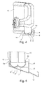
- FIG. 4 shows a heat exchanger 10, which is inserted into a support member 1.
- the heat exchanger 10 shown is in this case an evaporator and is in the FIG. 4 connected via pipes with an expansion valve.
- a support element 1 is attached to the heat exchanger 10 in an end region of the header tank.
- heat exchanger 10 are either plugged onto both end portions of a collecting tank, respectively, a support member 1, or attached to both end portions of both manifolds a support member 1.
- the w-shaped contour of the receiving area 2 is exactly adapted to the outer contour of the header of the heat exchanger 10.
- the receiving area 2 of the support member 1 in the unmounted state is smaller than the collection box of the heat exchanger 10. This creates a contact pressure in the mounted state, which exerts the support member 1 on the collection box of the heat exchanger 10. This leads in addition to a better connection and a secure fit of the support member 1 on the heat exchanger 10th
- FIG. 4 It is shown how the hook-like elements 5a, 5b engage behind the projection which is formed between the collecting box and the heat transfer matrix. Characterized the support member 1 is fixed to the heat exchanger 10.
- FIG. 4 a wall 9 indicated, which belongs to a receiving device of an air conditioner.
- the spacer element 4 is supported and thus also the heat exchanger 10 on the wall 9 from. It thus spaces the heat exchanger 10 relative to the wall 9.
- the two support elements which are each pushed from a lateral end region via a collecting box, are connected to one another with a profile.
- the profile can advantageously be generated from a soft plastic, so that it assumes an additional sealing and balancing effect.
- the profile is designed so that it covers in particular the transition between the pipe and rib area of the heat exchanger and the collecting box. In this way, a leakage flow around the collection box can be reduced.
- the profile may include the entire outer contour of the header box, or even partial areas. If the collecting box is completely enclosed, openings may be provided, via which, for example, condensate can run off.
- FIG. 5 shows a section along the air flow direction of the heat exchanger 10 through the collection box area of the heat exchanger 10.
- the heat exchanger 10 is in the FIG. 5 inserted into a receiving device 12.
- the wall 9 forms a first spatial boundary of the receiving device 12, in which the heat exchanger 10 can be inserted.
- the area of the receiving device 12 is further limited in space.
- the depth of the receiving device 12, which results between the wall 9 and the wall 13, in this case corresponds to a measure which is constant regardless of the heat exchanger 10 actually used.
- the heat exchanger 10 is positioned in this area and fixed between the wall 13 and the wall 9.
- a heat exchanger 10 is also providable, which one of the in FIG. 5 having shown heat exchanger 10 deviating degree.
- the support member 1 is adjusted accordingly.
- the length of the spacer element 4 can be varied.
- the receiving region 2, which is formed from the two arcuate regions 7, 8 and the bead-shaped region 6, can be adapted to the respective heat exchanger 10. In this way, the positioning of heat exchangers with different dimensions in a recording device 12 constant depth is possible.
- FIG. 5 sits the heat exchanger 10 with the support member 1 on the receiving device 12 and is supported to the left with the arcuate portion 8 against the wall 13 and on the opposite side with the spacer element 4 on the wall.
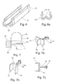
- FIG. 6 shows a perspective view of an arrangement of two support members 30 with a profile 31 that connects the two support members 30.
- the support members 30 are preferably made of a hard plastic and connected to a profile 31 made of an elastic plastic.
- the support members 30 and the profile 31 are formed so that they can embrace a collection box of a heat exchanger at least partially.
- the profile 31 may for example consist of a foam and so assume an additional sealing and decoupling function.
- the support members 30 and the profile 31 may be formed of a metallic material or as a two-component embodiment of a hard material, which is at least partially enclosed by a soft material, such as a foam.
- profile 31 individual profile strips can be provided, which connect the two support members 30 together.
- FIG. 6a shows a section through a support member 34.
- the support member 34 is wrapped with a sheath 32.
- the support member 34 has a projection 33, made of a foam, in its receiving area.
- the sheath which advantageously consists of a foam sheath, serves to decouple and seal a heat exchanger.
- FIG. 7 1 shows a sectional view through a heat exchanger 19. This consists essentially of a collecting box 18 and a tube-rib block 20. A holding element 21 is guided through the tube-rib block 20, which receives the tube-rib block 20 of the heat exchanger 19 along a receiving area 16.
- the support member 21 has a stopper member 15 which abuts against one of the outer surfaces of the tube-fin block. At the stop element 15, a spacer element 14 is arranged.
- the support member 21 is used to space the heat exchanger 19 to a surrounding the heat exchanger 19 housing.
- the retaining element 21 has hook-like elements 17 at the end region of the receiving region 16, which is formed by two web-like elements.
- the support member 21 can be pushed with these hook-like elements 17 through the tube-fin block 20 of the heat exchanger 19.
- the hook-like elements 17 engage behind the tube-rib block 20 on the side opposite the stop element 15 and thus fix the holding element 21 in the tube-rib block 20.
- the Figure 7a shows a perspective view of the support member 21, as it is already in FIG. 7 is described.
- the spacer element 14 can be arranged both centrally, and offset from the center of the stop element 15 out.
- FIG. 7b shows an alternative embodiment of the support member 21.
- the stop member 15 has two spacers 14 in this embodiment.
- FIG. 7c shows a plan view of the support member according to the FIG. 7b .
- the in the Figures 7, 7a, 7b and 7c shown embodiments of the alternative support member 21 may each be made of the same materials as the support member 1 of the FIGS. 1 to 5 be made.
- the hook-like elements 17 may also have different shapes in alternative embodiments.
- Task of the hook-like elements 17 is to fix the support member 21 on the heat exchanger 19.
- clips can be provided for fixing the support member 21 in the heat exchanger 19, for example.
Landscapes
- Engineering & Computer Science (AREA)
- Physics & Mathematics (AREA)
- Thermal Sciences (AREA)
- Mechanical Engineering (AREA)
- General Engineering & Computer Science (AREA)
- Heat-Exchange Devices With Radiators And Conduit Assemblies (AREA)
- Details Of Heat-Exchange And Heat-Transfer (AREA)
- Air-Conditioning For Vehicles (AREA)
- Air Filters, Heat-Exchange Apparatuses, And Housings Of Air-Conditioning Units (AREA)
Applications Claiming Priority (1)
| Application Number | Priority Date | Filing Date | Title |
|---|---|---|---|
| DE102012218089.3A DE102012218089A1 (de) | 2012-10-04 | 2012-10-04 | Wärmeübertrager und Halterungselement |
Publications (2)
| Publication Number | Publication Date |
|---|---|
| EP2717009A2 true EP2717009A2 (fr) | 2014-04-09 |
| EP2717009A3 EP2717009A3 (fr) | 2014-08-27 |
Family
ID=49322224
Family Applications (1)
| Application Number | Title | Priority Date | Filing Date |
|---|---|---|---|
| EP13187181.6A Withdrawn EP2717009A3 (fr) | 2012-10-04 | 2013-10-02 | Échangeur de chaleur doté d'un élément de support |
Country Status (4)
| Country | Link |
|---|---|
| US (1) | US9593892B2 (fr) |
| EP (1) | EP2717009A3 (fr) |
| CN (1) | CN203628986U (fr) |
| DE (1) | DE102012218089A1 (fr) |
Families Citing this family (5)
| Publication number | Priority date | Publication date | Assignee | Title |
|---|---|---|---|---|
| US9146061B2 (en) * | 2013-05-06 | 2015-09-29 | Denso International America, Inc. | Fastener-less retained heat exchanger mounting bracket for low installation force |
| DE102014207487A1 (de) * | 2014-04-17 | 2015-10-22 | MAHLE Behr GmbH & Co. KG | Baukastensystem für eine Verdampfereinrichtung |
| DE102015103908A1 (de) | 2015-03-17 | 2016-09-22 | Denso Automotive Deutschland Gmbh | Zusammenbauanordnung eines Wärmetauschers |
| JP6350373B2 (ja) * | 2015-04-17 | 2018-07-04 | 株式会社デンソー | 蒸発器 |
| CN109642778B (zh) * | 2016-08-01 | 2020-04-21 | 株式会社电装 | 空调单元 |
Family Cites Families (23)
| Publication number | Priority date | Publication date | Assignee | Title |
|---|---|---|---|---|
| US3850146A (en) * | 1973-01-15 | 1974-11-26 | D Frame | Boiler tube shielding wall |
| US3938587A (en) * | 1975-01-06 | 1976-02-17 | Hayden Trans-Cooler, Inc. | Cooler fastening system |
| JPS6046335U (ja) * | 1983-09-02 | 1985-04-01 | マツダ株式会社 | 自動車のラジエ−タ支持構造 |
| JP3043025B2 (ja) * | 1990-02-01 | 2000-05-22 | 昭和アルミニウム株式会社 | 熱交換器 |
| US5570737A (en) * | 1993-10-07 | 1996-11-05 | Showa Aluminum Corporation | Heat exchanger |
| BR9708974A (pt) * | 1996-05-04 | 1999-08-03 | Ford Motor Co | Montagem de radiador e condensador |
| KR100361768B1 (ko) * | 1997-11-28 | 2002-11-22 | 미쯔비시 헤비 인더스트리즈 리미티드 | 수관 보호용 내화 구조체와 그 조립방법 |
| FR2772902B1 (fr) * | 1997-12-24 | 2000-03-03 | Valeo Thermique Moteur Sa | Dispositif d'assemblage d'accessoires sur un radiateur de refroidissement de vehicule |
| US20010004010A1 (en) * | 1998-02-09 | 2001-06-21 | Immanuel Halm | Heat exchanger having snap-on bracket |
| FR2793741B1 (fr) * | 1999-05-20 | 2001-08-10 | Peguform France | Dispositif de fixation d'un radiateur sur un support d'un vehicule |
| GB2373571B (en) * | 2001-03-23 | 2004-11-03 | Visteon Global Tech Inc | Heat exchanger |
| JP2003089313A (ja) * | 2001-09-18 | 2003-03-25 | Denso Corp | 車両用空調装置 |
| CA2366227C (fr) * | 2001-12-27 | 2007-12-04 | John W. Izard | Support de fixation pour faisceaux d'echangeur de chaleur |
| US7287574B2 (en) * | 2002-02-11 | 2007-10-30 | Valeo, Inc. | Attachment and articles using same |
| FR2838792B1 (fr) * | 2002-04-18 | 2004-10-29 | Plastic Omnium Cie | Dispositif de fixation d'un organe fonctionnel sur une piece de structure de vehicule automobile et piece de structure integrant partiellement un tel dispositif |
| US7059392B2 (en) * | 2003-07-11 | 2006-06-13 | Newfrey Llc | Radiator attachment assemblies, apparatus components, and methods |
| DE102004017339A1 (de) * | 2004-04-06 | 2005-10-27 | Behr Gmbh & Co. Kg | Dichtungsanordnung für einen Wärmeübertrager |
| US7117927B2 (en) * | 2004-09-14 | 2006-10-10 | Delphi Technologies, Inc. | Snap-on mounting bracket for heat exchangers |
| JP4830700B2 (ja) * | 2006-04-21 | 2011-12-07 | 株式会社デンソー | クーリングモジュール |
| FR2922823B1 (fr) * | 2007-10-25 | 2009-12-18 | Renault Sas | Agencement pour le montage d'un echangeur thermique sur un element de structure vertical formant une face avant technique de vehicule automobile. |
| US8499823B1 (en) * | 2008-04-18 | 2013-08-06 | One Source | Twin heat transfer tubing retention panel |
| US20110073277A1 (en) * | 2008-07-23 | 2011-03-31 | Karl Andrew E | Adapter for heat exchanger |
| EP2189746A1 (fr) * | 2008-11-24 | 2010-05-26 | Behr GmbH & Co. KG | Partie de fixation destinée à la fixation d'un caloporteur |
-
2012
- 2012-10-04 DE DE102012218089.3A patent/DE102012218089A1/de not_active Ceased
-
2013
- 2013-09-13 CN CN201320570544.2U patent/CN203628986U/zh not_active Expired - Fee Related
- 2013-10-02 EP EP13187181.6A patent/EP2717009A3/fr not_active Withdrawn
- 2013-10-03 US US14/044,923 patent/US9593892B2/en not_active Expired - Fee Related
Non-Patent Citations (1)
| Title |
|---|
| None |
Also Published As
| Publication number | Publication date |
|---|---|
| US9593892B2 (en) | 2017-03-14 |
| US20140096932A1 (en) | 2014-04-10 |
| CN203628986U (zh) | 2014-06-04 |
| EP2717009A3 (fr) | 2014-08-27 |
| DE102012218089A1 (de) | 2014-04-10 |
Similar Documents
| Publication | Publication Date | Title |
|---|---|---|
| EP3093172B1 (fr) | Systeme d'assemblage d'un echangeur thermique | |
| EP2717009A2 (fr) | Échangeur de chaleur doté d'un élément de support | |
| WO2012034687A1 (fr) | Unité de ventilateur comprenant un ventilateur axial électrique | |
| DE112010002428T5 (de) | Montageaufbau für einen Clip an einem montagefähigen Glied | |
| DE102013109233A1 (de) | Verbinder | |
| EP4350155B1 (fr) | Pince de fixation, système de fixation et ensemble toit | |
| EP2771636B1 (fr) | Échangeur de chaleur | |
| EP4169131B1 (fr) | Connecteur comprenant un support de contact avec deux barrettes de retenue adjacentes | |
| DE102013000628B4 (de) | Halterahmen einer Frischluftklappe eines Kraftfahrzeuges sowie Frischluftklappe mit Halterahmen | |
| WO2013174839A1 (fr) | Cadre d'insertion conçu pour un échangeur thermique | |
| DE202010010620U1 (de) | Bodenabdeckung | |
| DE102011051613A1 (de) | Befestigungssystem für einen Kraftfahrzeugdachträger | |
| EP2146169B1 (fr) | Dispositif de fixation d'un condensateur de liquide de refroidissement sur un refroidisseur de liquide de refroidissement | |
| DE102007020187A1 (de) | Plattenwärmetauscher | |
| DE102010046315B4 (de) | Klimaanlage für Kraftfahrzeuge | |
| DE102009037304A1 (de) | Kraftfahrzeugklimaanlage | |
| EP4293266B1 (fr) | Manchon de paroi pour un boîtier de mur, boîtier de mur et agencement d'un boîtier de mur et d'un mur | |
| DE102005030885B4 (de) | Anlagengehäuse, insbesondere für eine Heiz-, Belüftungs- und/oder Klimaanlage eines Fahrzeugs | |
| EP2742568B1 (fr) | Frein de brosse | |
| WO2008025444A1 (fr) | module de sac à gaz en rideau | |
| DE202017100199U1 (de) | Heizungs-, Lüftungs- und/oder Klimatisierungsvorrichtung für ein Kraftfahrzeug | |
| EP2336662B1 (fr) | Elément de liaison pour relier deux canaux d'aération | |
| DE102020214025A1 (de) | Aufdachklimaanlage für Fahrzeuge | |
| EP2110632A1 (fr) | Echangeur thermique, en particulier refroidisseur d'air de suralimentation, doté d'un dispositif de fixation par clips | |
| EP1652704B1 (fr) | Ensemble de chauffage électrique, notamment pour véhicule automobile |
Legal Events
| Date | Code | Title | Description |
|---|---|---|---|
| PUAI | Public reference made under article 153(3) epc to a published international application that has entered the european phase |
Free format text: ORIGINAL CODE: 0009012 |
|
| AK | Designated contracting states |
Kind code of ref document: A2 Designated state(s): AL AT BE BG CH CY CZ DE DK EE ES FI FR GB GR HR HU IE IS IT LI LT LU LV MC MK MT NL NO PL PT RO RS SE SI SK SM TR |
|
| AX | Request for extension of the european patent |
Extension state: BA ME |
|
| PUAL | Search report despatched |
Free format text: ORIGINAL CODE: 0009013 |
|
| AK | Designated contracting states |
Kind code of ref document: A3 Designated state(s): AL AT BE BG CH CY CZ DE DK EE ES FI FR GB GR HR HU IE IS IT LI LT LU LV MC MK MT NL NO PL PT RO RS SE SI SK SM TR |
|
| AX | Request for extension of the european patent |
Extension state: BA ME |
|
| RIC1 | Information provided on ipc code assigned before grant |
Ipc: F28F 9/00 20060101ALI20140723BHEP Ipc: F28F 9/007 20060101AFI20140723BHEP |
|
| RAP1 | Party data changed (applicant data changed or rights of an application transferred) |
Owner name: MAHLE BEHR GMBH & CO. KG |
|
| STAA | Information on the status of an ep patent application or granted ep patent |
Free format text: STATUS: THE APPLICATION IS DEEMED TO BE WITHDRAWN |
|
| 18D | Application deemed to be withdrawn |
Effective date: 20150228 |