EP2717052A2 - Appareil de criblage à haute vitesse de plusieurs médicaments par analyse raman - Google Patents
Appareil de criblage à haute vitesse de plusieurs médicaments par analyse raman Download PDFInfo
- Publication number
- EP2717052A2 EP2717052A2 EP12794000.5A EP12794000A EP2717052A2 EP 2717052 A2 EP2717052 A2 EP 2717052A2 EP 12794000 A EP12794000 A EP 12794000A EP 2717052 A2 EP2717052 A2 EP 2717052A2
- Authority
- EP
- European Patent Office
- Prior art keywords
- raman
- images
- sample
- core
- screening apparatus
- Prior art date
- Legal status (The legal status is an assumption and is not a legal conclusion. Google has not performed a legal analysis and makes no representation as to the accuracy of the status listed.)
- Withdrawn
Links
Images





Classifications
-
- G—PHYSICS
- G01—MEASURING; TESTING
- G01N—INVESTIGATING OR ANALYSING MATERIALS BY DETERMINING THEIR CHEMICAL OR PHYSICAL PROPERTIES
- G01N33/00—Investigating or analysing materials by specific methods not covered by groups G01N1/00 - G01N31/00
- G01N33/48—Biological material, e.g. blood, urine; Haemocytometers
- G01N33/50—Chemical analysis of biological material, e.g. blood, urine; Testing involving biospecific ligand binding methods; Immunological testing
- G01N33/58—Chemical analysis of biological material, e.g. blood, urine; Testing involving biospecific ligand binding methods; Immunological testing involving labelled substances
- G01N33/585—Chemical analysis of biological material, e.g. blood, urine; Testing involving biospecific ligand binding methods; Immunological testing involving labelled substances with a particulate label, e.g. coloured latex
- G01N33/587—Nanoparticles
-
- G—PHYSICS
- G01—MEASURING; TESTING
- G01N—INVESTIGATING OR ANALYSING MATERIALS BY DETERMINING THEIR CHEMICAL OR PHYSICAL PROPERTIES
- G01N21/00—Investigating or analysing materials by the use of optical means, i.e. using sub-millimetre waves, infrared, visible or ultraviolet light
- G01N21/62—Systems in which the material investigated is excited whereby it emits light or causes a change in wavelength of the incident light
- G01N21/63—Systems in which the material investigated is excited whereby it emits light or causes a change in wavelength of the incident light optically excited
- G01N21/65—Raman scattering
- G01N21/658—Raman scattering enhancement Raman, e.g. surface plasmons
-
- G—PHYSICS
- G01—MEASURING; TESTING
- G01N—INVESTIGATING OR ANALYSING MATERIALS BY DETERMINING THEIR CHEMICAL OR PHYSICAL PROPERTIES
- G01N33/00—Investigating or analysing materials by specific methods not covered by groups G01N1/00 - G01N31/00
- G01N33/15—Medicinal preparations ; Physical properties thereof, e.g. dissolubility
-
- G—PHYSICS
- G01—MEASURING; TESTING
- G01N—INVESTIGATING OR ANALYSING MATERIALS BY DETERMINING THEIR CHEMICAL OR PHYSICAL PROPERTIES
- G01N21/00—Investigating or analysing materials by the use of optical means, i.e. using sub-millimetre waves, infrared, visible or ultraviolet light
- G01N21/62—Systems in which the material investigated is excited whereby it emits light or causes a change in wavelength of the incident light
- G01N21/63—Systems in which the material investigated is excited whereby it emits light or causes a change in wavelength of the incident light optically excited
- G01N21/65—Raman scattering
-
- G—PHYSICS
- G02—OPTICS
- G02B—OPTICAL ELEMENTS, SYSTEMS OR APPARATUS
- G02B21/00—Microscopes
- G02B21/36—Microscopes arranged for photographic purposes or projection purposes or digital imaging or video purposes including associated control and data processing arrangements
- G02B21/365—Control or image processing arrangements for digital or video microscopes
- G02B21/367—Control or image processing arrangements for digital or video microscopes providing an output produced by processing a plurality of individual source images, e.g. image tiling, montage, composite images, depth sectioning, image comparison
-
- H—ELECTRICITY
- H04—ELECTRIC COMMUNICATION TECHNIQUE
- H04N—PICTORIAL COMMUNICATION, e.g. TELEVISION
- H04N25/00—Circuitry of solid-state image sensors [SSIS]; Control thereof
- H04N25/70—SSIS architectures; Circuits associated therewith
- H04N25/71—Charge-coupled device [CCD] sensors; Charge-transfer registers specially adapted for CCD sensors
Definitions
- the present invention relates to a Raman analysis-based apparatus for screening multiple drugs at a high speed.
- Drug development is an advanced country-type strategic process requiring a massive commitment of time and money of more than ten years and eight hundred million dollars, respectively.
- a well-developed social infrastructure is also necessary for drug development.
- the process of drug development can be divided into the discovery of a drug target by basic research, the selection of effective and lead materials by compound screening, the determination of a candidate drug, clinical research through pre-clinical work/clinical phase 1, and commercialization through clinical phases 2 and 3.
- the screening method can be divided into an in vitro assay and a cell-based assay.
- Major pharmaceutical companies possess libraries of compounds, typically amounting in number to ten of thousands to hundreds of millions, as screening targets, and such a number of compounds are employed from an early screening stage.
- a screening process for many compounds must be technically simple with high reproducibility.
- a drug target is an enzyme
- a relative easy approach is possible thanks to an abundant number of screening methods and reagents established therefor.
- a screening method based on interaction with proteins is the most effective among analysis methods for developing lead compounds.
- a protein functions as it associates with another protein in vivo; a change in gene and protein expression, in intracellular location, and/or in structure through post-translational modification induces an altered interaction between proteins, resulting in a change in the activity and regulation of intracellular metabolisms and signaling pathways; and an abnormal protein interaction attributed to a genetic mutation directly leads to the onset of a disease.
- technologies for detecting protein interactions including FRET (fluorescence Resonance Energy Transfer), BRET (Bioluminescence Resonance Energy Transfer) and FP (Fluorescence Polarization), and a technical advance has also been achieved in apparatuses to which the technologies are applicable.
- HCS high-content screening
- multiwell plates such as 96-well, 384-well plates, etc.
- phenomena associated with the quantitative change and transport of proteins within cells can be rapidly observed in a quantitative manner.
- HCS is now arising as the most interesting biological research method for world-leading pharmaceutical companies or research institutes because it allows the quantitative analysis of biological parameters, such as protein interaction, Ca ++ influx, etc., which are difficult to screen on a large scale with conventional methods, over the simple information obtained using conventional enzyme detection methods or reporter systems, for example, on enzyme activity, promoter strength, protein levels, etc.
- a procedure for drug screening comprises preparation of compound aliquots, dilution, mixing of screening components, culturing and detection, analysis of screening data, and reporting on results.
- a high-throughput screening (hereinafter referred to as "HTS") system is used to rapidly process such a serial procedure.
- HTS high-throughput screening
- Advanced pharmaceutical companies are known to possess a compound library consisting of hundreds of millions of different compounds, and whenever a novel drug target is discovered, the companies take advantage of the HTS system in screening the compound library against the drug target.
- major pharmaceutical companies have accumulated tremendous data on biological activities of hundreds of millions of compounds, thus far.
- a curve-fitting tool capable of performing various functions including a QC function, error checking for overlapped data, calculation of relative activity (% activity), and extraction of biochemical parameters, such as IC 50 , K i , and K m .
- HTS which allows much data to be produced by one screening process is required.
- This new technology aiming to overcoming problems associated with the conventional technology, is basically designed to evaluate synthetic compounds randomly on a mass scale through automation, and can reduce the time taken to determine candidate drugs as much as possible in association with automated synthesis of new materials (CCL), molecular design and systematic information management.
- High-content screening can be defined as a "technology for functionally and complexly screening various targets inside living cells on the basis of highly temporally and spatially resolved fluorescence images.”
- fundamental technologies of HCS are a cell-based assay, real-time fluorescent imaging of living cells with high temporal and spatial resolution, and a high-speed and high-content automated assay.
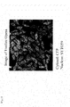
- Representative of HCS analysis instruments is the Opera system of Perkin-Elmer shown in FIG. 1 .
- Formal cell analysis data obtained by the Opera system is as shown in FIG. 2 .
- images of tens of aggregated cells are obtained within a field, and cell nuclei and walls are discriminated among the images, during which images of some cells are removed on the program while leaving significant cell images.
- two-color images are obtained as seen in FIG. 2 .
- the high-content screening technology has been based on fluorescence assay, so far.
- fluorescent labels used in fluorescence assay weaken in fluorescence intensity (photobleaching), and exhibit interference between different fluorescent labels because excitation light with a very narrow wavelength range is used while the fluorescent light has a very broad range of wavelengths.
- SERS Surface Enhanced Raman Scattering
- a fraction of the incident photons interact with the molecules in such a way that energy is gained or electrons are excited into higher energy levels, so that the scattered photons have a different frequency from that of the incident photons.
- Raman spectroscopy together with the nanotechnology which is currently being quickly developed, can be further developed for highly sensitive detection of a single molecule.
- an SERS sensor can be importantly used as a medical sensor.
- the SERS effect is in relation with plasmon resonance.
- metal nanoparticles exhibit apparent optical resonance in response to incident electromagnetic radiation due to the collective coupling of conduction electrons within the metal.
- nanoparticles of gold, silver, copper and other specific metals can fundamentally serve as nanoscale antenna for amplifying the localization of electromagnetic radiation. Molecules localized in the vicinity of these particles show far greater sensitivity to Roman spectroscopy.
- SERS Surface-Enhanced Raman Scattering
- the one object of the present invention may be accomplished by providing a high-speed screening apparatus of multiple drugs using surface-enhanced Raman scattering, comprising: an excitation module, composed of a lens, a mirror, and a pinhole, for introducing light from a light source into a microscope; a microscope module for acquiring an image of a sample, comprising a motion controller for controlling a position of the sample, a filtration unit composed of one or more Raman filters for filtering Raman wavelengths against light scattered from the sample when the sample is irradiated with excitation light from the light source, and a detector for sequentially receiving light beams passing through the filtration unit; and an image processing module for coding colors for a set of images obtained from a point containing a sample to produce cell or tissue images, and for displaying the cell or tissue images, said point being positioned by the motion controller.
- the high-speed screening apparatus may further comprise a storage chamber for storing core-gap-shell nanoparticles.
- the other object of the present invention may be accomplished by providing a high-speed screening method of multiple drugs using surface enhanced Raman scattering, comprising: adding the core-gap-shell nanoparticles of claim 10 to a sample to be analyzed (step 1); obtaining one or more Raman images from the sample by irradiating a laser beam own the sample to generate Raman scattered light, filtering the Raman scattered light through a filtration unit composed of one or more Roman filters to extract a Raman wavelength of interest, and detecting the Raman spectrum using a detector (step 2); and coding colors for the Raman images of the sample to generate cell or tissue images and displaying the cell or tissue images (step 3).
- the screening apparatus and method of the present invention is not designed to detect autofluorescence, but to measure Raman signals generated from core-gap-shell nanoparticles, so that it exhibits no interference between fluorescent labels.
- the core-gap-shell nanoparticles show very strong surface-enhanced Roman scattering (SERS) signals, with an SERS enhancement factor of up to about 10 12 , and are proven to be highly reproducible.
- SERS surface-enhanced Roman scattering
- the use of a CCD camera as a detector allows the apparatus and method of the present invention to screen multiple drugs at a high speed because the CCD camera, which operates in a non-scanning manner, can photograph individual wells of well plates momentarily and can take pictures of other wells in association with the operation of the motion controller.
- the apparatus and method of the present invention can code multiple colors for Raman images, and are effectively applicable to the screening of various drugs.
- the present invention addresses a high-speed screening apparatus of multiple drugs using surface-enhanced Raman scattering, comprising:
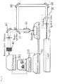
- FIG. 3 is a conceptual view of a Raman-based high-speed screening apparatus of multiple drugs according to the present invention.
- the Raman-based high speed screening apparatus of multiple drugs according to the present invention may be divided into an excitation module, a microscope module, and an image processing module. It should be apparent to those skilled in the art that the functional modules are intended simply for concrete descriptions thereof, but not to divide them into exclusive and independent parts, and that the functional modules may be overlapped in certain regions or two or more functional modules may participate in one region.
- the excitation module functions to introduce a laser beam generated from a light source (LS) 10 into a microscope.
- the LS 10 may generate a near infrared (NIR) laser or a visible laser.
- the visible laser is light with a wavelength of from 400 to 700 nm. In one embodiment, the visible laser has a wavelength of 514.5 nm.
- Raman images have been obtained mainly using an NIR laser since the use of visible light as a light source induces autofluorescence, which brings about a reduction in the intensity of Raman signals.
- Raman signal strength is in inverse proportion to a fourth power of wavelength
- a visible laser can increase the intensity of Raman signals further than can an NIR laser.
- optical devices utilizing visible light are more advanced than those using NIR light. Hence, if it can reduce autofluorescence, the use of visible lasers has an advantage over that of NIR lasers in optimizing an optical system.
- a laser beam After being generated by the LS 10, a laser beam passes through a spatial filter 20 so that the beam diameter expands. Through a plurality of lenses, a mirror, and a pinhole, the beam is collimated to have a diameter of about 10 mm, and then introduced into a microscope module.
- the microscope module comprises a motion controller 50 for controlling the position of a sample, a Raman filtration unit 40 consisting of one or more Raman filters for filtering Raman wavelength light against scattered light from the sample when the sample irradiated with excitation light from a laser beam, and a detector 111 for sequentially receiving light beams passing through the Raman filtration unit 40.
- the laser beam After entry into a microscope, the laser beam is reflected by a light separation unit 21 and is directed toward a microscope objective (MO) lens 30.
- a beam splitter, a dichroic mirror, or a detachable mirror may be used.
- the number of the Raman filters for filtering Raman wavelength light is in the order of 1 to 20, and preferably in the order 5 to 20.
- the Raman filtration unit may be a band pass filter, and preferably includes, but is not limited to, a narrow band pass filter.
- any detector may be employed in the present invention.
- PMT photomultiplier tube
- APD avalanche photodiode detectors
- CCD charge-coupled device
- the sample may be a cell containing an analyte.
- the analyte of interest include amino acids, peptides, polypeptides, proteins, glycoproteins, lipoproteins, nucleosides, nucleotides, oligonucleotides, nucleic acids, saccharides, carbohydrates, oligosaccharides, polysaccharides, fatty acids, lipids, hormones, metabolites, cytokines, chemokines, receptors, neurotransmitters, antigens, allergens, antibodies, substrates, metabolites, co-factors, inhibitors, drugs, pharmaceuticals, nutrients, prions, toxins, poisons, explosives, pesticides, chemical warfare agents, biohazardous agents, radioisotopes, vitamins, heterocyclic aromatic compounds, carcinogens, mutagens, narcotics, amphetamines, barbiturates, hallucinogens, waste products and contaminants.
- the analyte when it is a nucleic acid, it may be exemplified by genes, viral RNA and DNA, bacterial DNA, fungal DNA, mammalian DNA, cDNA, mRNA and DNA fragments, oligonucleotides, synthetic oligonucleotides, modified oligonucleotides, single- and double-stranded nucleic acids, and natural and synthetic nucleic acids.
- the sample may be associated with a core-gap-shell nanoparticle shown in FIG. 4 so as to amplify Raman signals. The association may be achieved by exposing core-gap-shell nanoparticles stored in a chamber (not shown) of the apparatus to the sample.
- the core-gap-shell is designed to have a biomolecule functionalized on the surface of the shell which can recognize the analyte of interest.
- the core-gap-shell nanoparticles When exposed to a sample, they selectively bind to the analyte of interest and can be ready for imaging.
- biomolecules functionalized on the nanoparticles may be antibodies, antibody fragments, genetically modified antibodies, single-chain antibodies, receptor proteins, ligand proteins, enzymes, inhibitor proteins, lectins, cell adhesion proteins, oligonucleotides, polynucleotides, nucleic acids, and aptamers.
- Functionalization may be accomplished by, but is not limited to, attaching a biomolecule onto a nanoparticle via an electrostatic force, or by binding a biomolecule to a nanoparticle directly or via a linker.
- the core-gap-shell nanoparticle comprises a core, a shell surrounding the core, and a nanogap formed between the core and the shell.
- the core is connected with the shell via a nanobridge or is not connected with the shell, with the nanogap containing an optically active molecule therein.
- any optically active molecule may be used in the present invention.
- a metal ion, a chelator of metal ions, or a metal nanoparticle may be employed.
- a signal substance used in the present invention is a broad concept encompassing fluorescent organic molecules, non-fluorescent organic molecules, inorganic nanoparticles, and Raman active molecules, and refers to a chromogenic labelling substance without limitations imparted thereto. Preferred is a Raman active molecule.
- Raman active molecule refers to a molecule that facilitates the detection and measurement of an analyte by a Raman detection apparatus after the nanoparticle of the present invention is bound to at least one analyte.
- Raman active molecules available for Raman spectroscopy may be organic atoms or molecules, or inorganic atoms or molecules.
- Raman active molecules useful in the present invention include, but are not limited to, FAM, Dabcyl, TAMRA, TRITC (tetramethyl rhodamine -5-isothiocyanate), MGITC (malachite green isothiocyanate), XRITC (X-rhodamine-5-isothiocyanate), DTDC (3,3-diethylthiadicarbocyanine iodide), TRIT (tetramethyl rhodamineisothiol), NBD (7-nitrobenz-2-1,3-diazole), phthalic acid, terephthalic acid, isophthalic acid, para-aminobenzoic acid, erythrosine, biotin, digoxigenin, 5-carboxy-4',5'-dichloro-2',7'-dimethoxy, fluorescein, 5-carboxy-2',4',5',7'-tetrachlorofluorescein, 5-
- the Raman active molecule is required to show a clear Raman spectrum and must be associated or related with different kinds of analytes.
- the optical active molecule may be confined within the nanogap.
- the optically active molecule is modified via a covalent bond or electrostatic attraction with the biomolecule functionalized on the nanoparticle so that it is positioned in an interior gap.
- the optically active molecule may be attached onto the surface of the core particle via a covalent bond or electrostatic attraction irrespective of the biomolecule.
- Modification with the biomolecule has the advantage of controlling the position of the optically active molecule. In detail, if it is modified at a position near the end of the biomolecule attached onto the core, the optically active molecule may be located near the core. In this manner, the optically active molecule can be positioned within the nanogap.
- Raman signals may vary depending on the position of the optically active molecule. For example, when the optically active molecule is positioned in the interior gap, the strongest Raman signals can be detected, with high uniformity and reproducibility.
- kinds of the optically active molecule confined within the nanogap of the core-gap-shell determine certain Raman peaks generated.
- the Raman peaks are detected through corresponding Raman filters by a detector, such as CCD, to acquire images of the sample (cell). These images are color coded by a computer program and then displayed.
- core refers to a spherical or sphere-like particle with a diameter of 1 - 900 nm, consisting of a metal exhibiting surface plasmon resonance, such as gold, silver or copper.
- the term "shell” refers to a coating layer surrounding the core, composed of a metal exhibiting surface plasmon resonance.
- the shell ranges in thickness from 0.1 to 900 nm and preferably from 1 nm to 100 nm. Between the core and the shell, a space, called a nanogap, is formed. Gold, silver or copper may be used as the metal exhibiting surface plasmon resonance.
- the term "nanogap” means a space formed between the core and the shell.
- the thickness of the nanogap is preferably in the order of 0.01 to 100 nm.
- the core may be discriminated from the shell by the nanogap.
- the core and the shell may not contact each other where the nanogap is formed while contacting each other through a nanobridge. That is, the "nanogap" does not mean a space by which the core and the shell are completely separated from each other.
- nanobridge refers to a bridge with a diameter of 0.5 to 20 nm through which the core is connected with the shell.
- the nanoparticle may comprise a “nanobridged nanogap” or a “nanobridgeless nanogap.”
- optically active molecule refers to a molecule that produces Raman scattering beams in response to excitation light. Located between the core and the shell, both exhibiting surface plasmon resonance, the optically active molecule exerts a maximum surface-enhanced Raman scattering effect.
- the core-gap-shell nanoparticle may be selected from the group consisting of i) a nanoparticle consisting of a gold core and a silver shell with a nanogap formed between the gold core and the silver shell, ii) a nanoparticle consisting of a silver core and a gold shell with a nanogap formed between the silver core and the gold shell, iii) a nanoparticle consisting of a gold core and a gold shell with a nanogap formed between the gold core and the gold shell, and iv) a nanoparticle consisting of a silver core and a silver shell with a nanogap formed between the silver core and the silver shell.
- a nanoparticle consisting of a gold core and a gold shell with a nanogap formed therebetween No particular limitations are imparted to the morphology of the core.
- the core may be connected with the shell via a nanobridge. That is, a shell may be established over the core in such a way that the shell touches the core surface in some parts to form nanobridges, and the nanobridged nanogap is formed along the core surface.
- the number of nanobridges is not particularly constrained so long as it guarantees the formation of the nanogap.
- the nanobridge has a diameter of from 0.5 nm to 20 nm. The nanobridge functions to stably maintain the core-shell structure and increase the signal of SERS.
- the optically active molecule positioned in the nanogap between the core and the shell, exerts a maximum surface-enhanced Raman scattering (SERS) effect with the help of the plasmonic coupling at the nanogap between the core and the shell, thereby amplifying Raman signals.
- SERS surface-enhanced Raman scattering
- the nanogap structure can be synthesized with high reproducibility.
- the nanogap structure brings about exceptional improvements in the quantifiability of signals, the reproducibility of data, the ease and convenience of synthesis, the expense, and the stability of probes.
- the light emitted from the sample transverses the light separation unit 21 and then travels toward the Raman filtration unit 40 before detection by the detector 111.
- the Raman filtration unit may comprise one or more Raman filters through which only specific Raman wavelengths can pass, preferably 1 to 20 Raman filters, and more preferably 5 to 20 Raman filters.
- the light with different Raman wavelengths, emitted from the sample passes through a series of Raman filters for respective Raman wavelengths, so that specific Raman wavelengths are detected by the detector to obtain 1 to 20 multiple images.
- the Raman filtration unit may employ a band pass filter, and preferably a narrow band pass filter.
- the detector 111 for example, a CCD camera operating in a non-scanning manner, may be provided with a zoom lens to adjust magnification. Given a zoom lens, the detector can be improved in optical microscopic function, and allows for the observation of more concrete optical images.
- the motion controller 50 functions to locate the sample at a precise position fit to the focal point of the incident light by moving a stage on which a well plate containing the sample is loaded in the X or Y axis direction. After multiple images are obtained from one point (well) containing the sample according to the number of the Raman filters, another point is moved into the focal point by the motion controller 50 and is used for Raman imaging.
- a detector operating in a non-scanning manner for example, a CCD (charge-coupled device), can take Raman images from individual wells at a high speed, thus allowing for high-speed screening.
- CCD charge-coupled device
- the microscope module may be provided with an atmosphere maintainer (not shown) for maintaining the atmosphere of the external chamber in which the sample is positioned.
- the atmosphere maintainer may control conditions of the chamber, such as temperature, humidity, pH and the like.
- the image processing module functions to code colors for the single or plural Raman images obtained from the points, to convert the color-coded Raman images into cell or tissue images, and to display the cells or tissue images.
- the image processing module is a computer.
- the data obtained in the CCD camera is processed, and may be stored in a main memory unit. Data on emission profiles for standard analytes may also be stored in a main memory or ROM.
- the processor may compare emission spectra from analytes on a Raman-active substrate to discriminate kinds of the analytes.
- the processor analyzes the data from the detector to determine identities and/or concentrations of various analytes.
- different computers may be used for respective specific tasks. Thus, different system structures may be employed in different embodiments of the present invention.
- After collection thereof, the data is subjected to analysis. To facilitate data analysis, a high-performance digital computer may be recruited.
- the computer may be suitably programmed for analyzing and reporting collected data in addition to accommodating and storing the data.
- Respective different colors are coded for one or more Raman peaks detected through one or more Raman filters using software.
- the color-coded Raman images thus obtained are converted into and displayed as images of cells or biotissues on a monitor.
- the apparatus of the present invention can generate highly-resolved, surface-enhanced Raman scattering (SERS) spectra from one or more analytes present in a sample (e.g. cells) after one or more core-gap-shell nanoparticles are selectively associated with the analytes.
- SERS surface-enhanced Raman scattering
- the apparatus of the present invention can screen multiple drugs at a high speed because the CCD camera can photograph many wells within a short period of time in concert with the operation of the motion controller.
- the present invention addresses a method for screening multiple drugs at a high speed using surface enhanced Raman scattering, comprising:
- step 1 a reagent containing core-gap-shell nanoparticles is added to a sample comprising cells.
- the core-gap-shell nanoparticles are designed to have a biomolecule, capable of recognizing an analyte of interest, which is functionalized on the surface of the shell.
- the biomolecule binds to the analyte of interest, and thus can be ready for Raman imaging.
- the core-gap-shell nanoparticle may be selected from the group consisting of i) a nanoparticle consisting of a gold core and a silver shell with a nanogap formed between the gold core and the silver shell, ii) a nanoparticle consisting of a silver core and a gold shell with a nanogap formed between the silver core and the gold shell, iii) a nanoparticle consisting of a gold core and a gold shell with a nanogap formed between the gold core and the gold shell, and iv) a nanoparticle consisting of a silver core and a silver shell with a nanogap formed between the silver core and the silver shell.
- step 1 exposure of the core-gap-shell nanoparticles to an analyte may be performed inside or outside the screening apparatus of the present invention.
- Step 2 is designed to produce and capture one or more Raman images of the analyte of interest.
- a laser beam is irradiated on the sample to generate Raman scattered light which is then directed toward one or more Raman filters.
- specific Raman wavelengths are detected by a detector, for example, a CCD camera.
- the Raman filtration unit may comprise one or more Raman filters through which only specific Raman wavelengths can pass, preferably 1 to 20 Raman filters, and more preferably 5 to 20 Roman filters.
- the light with different Raman wavelengths, emitted from the sample passes through a series of Raman filters for respective Raman wavelengths, so that specific Roman wavelengths are detected by the detector to obtain 1 to 20 multiple images
- the Raman filtration unit may employ a band pass filter, and preferably a narrow band pass filter.
- the detector for example, a CCD camera, may be provided with a zoom lens to adjust the magnification. Given a zoom lens, the detector allows for the observation of optical images in more detail.
- step 3 colors are coded for the Raman images obtained in step 2, and the color-coded Raman images are converted into cell or tissue images which are then presented on a display.
- 1 to 20 colors are coded for the Raman images obtained in step 2 to produce color-coded Raman images ranging in multiplexity from 1 to 20 colors.
- the screening apparatus and method of the present invention exhibit no interference between fluorescent labels.
- the core-gap-shell nanoparticles show very strong surface-enhanced Raman scattering (SERS) signals, with an SERS enhancement factor of up to about 10 12 and are proven to be highly reproducible.
- SERS surface-enhanced Raman scattering
- the use of a CCD camera as a detector allows the apparatus and method of the present invention to screen multiple drugs at a high speed because the CCD camera, which operates in a non-scanning manner, can photograph individual wells of well plates momentarily, and can take pictures of other wells in association with the operation of the motion controller.
- the apparatus and method of the present invention can code multiple colors for Raman images, and is effectively applicable to the screening of various drugs.
- a DNA, strand was used as a Raman-dye modification platform with highly accurate position-controlling capability to synthesize an NNP (nanobridged nanogap particle) with a nanobridge-supported interior gap, as follows.
- DNA-modified gold nanoparticles (20 nm in diameter; DNA sequences: [3'-HS-(CH 2 ) 3 - (Dabcyl) -A 10 -PEG 18 -AAACTCTTTGCGCAC-5'] for Synthesis Example 1, [3'-HS-(CH 2 ) 3 -(Cy3)-A 10 -PEG 18 -AAACTCTTTGCGCAC-5'] for Synthesis Example 2, and [3'-HS-(CH 2 ) 3 -(TAMRA)-A 10 -PEG 18 -AAACTCTTTGCGCAC-5'] for Synthesis Example 3) were prepared according to literature procedures ( S. J. Hurst, A. K. R. Lytton-Jean, C. A.
- DNA-modified gold nanoparticles in a phosphate-buffered solution 0.3 M NaCl, 10 mM PB, pH 7.4
- a gold precursor HuCl 4
- a reductant NH 2 OH-HCl
- PVP poly-N-vinyl-2-pyrrolidone
- Amounts of the gold precursor and the reductant were controlled based on the amount of the seeds (DNA-modified gold nanoparticles, 1 nM) to monitor a nanoparticle morphology change during the course of gold shell formation.
- the DNA-modified gold nanoparticle solution (100 ⁇ L; 1 M in 0.3 M PBS) was mixed with 50 ⁇ L of a 1% PVP solution. The resulting solution was then mixed with 1.5, 5.2, 10.3 or 30.4 ⁇ L of hydroxylamine hydrochloride solution (10 mM) and 1.5, 5.2, 10.3 or 30.4 ⁇ L of chloroauric acid solution (5 nM), respectively. Depending on the amount of reagents used, various nanostructures were formed.
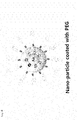
- mPEG-SH (MW ⁇ 5 kDa) was applied to the shell surface of the nanoparticles to prepare PEG-coated gold-silver core-shell nanoparticles (Synthesis Examples 4 to 6) with reference to ' W. Peter Wuelfing, Stephen M. Gross, Deon T. Miles, and Royce W. Murray, J. Am. Chem. Soc. 120, 12696 (1998 )'.
- SERS spectra were recorded by the apparatus of the present invention, that is, the in-house nano-Raman spectroscope equipped with an inverted optical microscope (Axiovert 200, Zeiss) using the nanoparticles synthesized in Synthesis Examples 1 to 3.
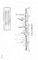
- FIG. 5 shows surface-enhanced Raman scattering spectra recorded by the apparatus of the present invention using nanoparticles synthesized in Synthesis Examples 1 to 3.
- FIG. 6 shows wavelength ranges of narrow band pass filters for selectively filtering Raman light scattered from the nanoparticles of Synthesis Examples 1 to 3.
- the nanoparticles synthesized in Synthesis Examples 1 to 3 have respective inherent Raman wavelength ranges, which enable the establishment of narrow band pass filters optimized to the nanoparticles.
- FIG. 7 shows Raman images detected after the selective filtration of Raman signals scattered from the nanoparticles synthesized in Synthesis Examples 1 to 3 through respective narrow band pass filters.
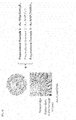
- FIG. 8 shows Raman images selectively filtered through respective narrow band pass filters optimized for the nanoparticles of Synthesis Examples 1 to 3, and a merged image thereof.
- the nanoparticles synthesized in Synthesis Examples 1 to 3 were selectively imaged only when the narrow band pass filters optimized thereto were employed. Moreover, a Raman image was obtained by merging the Raman scattered beams obtained from the nanoparticles of Synthesis Examples 1 to 3.
- Multicolor-coded cell images were obtained by the apparatus of the present invention using the nanoparticles synthesized in Synthesis Examples 4 and 5.
- HeLa cells cervical adenocarcinoma cell line
- a cell medium containing the nanoparticles synthesized in Synthesis Example 4 or 5 in an incubator.
- the cells were again washed with PBS, and fixed for 15 min with a chilled fixation buffer (BD Cytofix TM ). After removal of the fixation buffer, the cells were washed twice with PBS, and stored in PBS in a refrigerator until use.
- BD Cytofix TM chilled fixation buffer
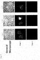
- FIG. 10 shows images of cells incubated without (a) (control) and with (b) (test group) the PEG-coated nanoparticles synthesized in Synthesis Example 5, as measured by the apparatus of the present invention using two narrow band pass filters ("Filter 1" and "Filter 2").
- FIG. 11 shows cell images of three sections of the test group incubated with the PEG-coated nanoparticles of Synthesis Example 4, as measured by the apparatus of the present invention using two narrow band pass filters ("Filter 1" and "Filter 2").
- FIG. 12 shows cell images of three sections of the test group incubated with the PEG-coated nanoparticles of Synthesis Example 5, as measured by the apparatus of the present invention using two narrow band pass filters ("Filter 1" and "Filter 2").
Landscapes
- Health & Medical Sciences (AREA)
- Life Sciences & Earth Sciences (AREA)
- Engineering & Computer Science (AREA)
- Chemical & Material Sciences (AREA)
- Physics & Mathematics (AREA)
- Analytical Chemistry (AREA)
- General Physics & Mathematics (AREA)
- Immunology (AREA)
- Biochemistry (AREA)
- General Health & Medical Sciences (AREA)
- Pathology (AREA)
- Multimedia (AREA)
- Molecular Biology (AREA)
- Nuclear Medicine, Radiotherapy & Molecular Imaging (AREA)
- Urology & Nephrology (AREA)
- Biomedical Technology (AREA)
- Hematology (AREA)
- Food Science & Technology (AREA)
- Medicinal Chemistry (AREA)
- Computer Vision & Pattern Recognition (AREA)
- Nanotechnology (AREA)
- Microbiology (AREA)
- Cell Biology (AREA)
- Biotechnology (AREA)
- Optics & Photonics (AREA)
- Signal Processing (AREA)
- Bioinformatics & Cheminformatics (AREA)
- Biophysics (AREA)
- Pharmacology & Pharmacy (AREA)
- Investigating, Analyzing Materials By Fluorescence Or Luminescence (AREA)
Applications Claiming Priority (3)
| Application Number | Priority Date | Filing Date | Title |
|---|---|---|---|
| KR20110050991 | 2011-05-29 | ||
| KR1020120056775A KR101361652B1 (ko) | 2011-05-29 | 2012-05-29 | 라만 분석 기반 고속 다중 약물 고속 스크리닝 장치 |
| PCT/KR2012/004223 WO2012165837A2 (fr) | 2011-05-29 | 2012-05-29 | Appareil de criblage à haute vitesse de plusieurs médicaments par analyse raman |
Publications (2)
| Publication Number | Publication Date |
|---|---|
| EP2717052A2 true EP2717052A2 (fr) | 2014-04-09 |
| EP2717052A4 EP2717052A4 (fr) | 2014-10-29 |
Family
ID=47260060
Family Applications (1)
| Application Number | Title | Priority Date | Filing Date |
|---|---|---|---|
| EP12794000.5A Withdrawn EP2717052A4 (fr) | 2011-05-29 | 2012-05-29 | Appareil de criblage à haute vitesse de plusieurs médicaments par analyse raman |
Country Status (8)
| Country | Link |
|---|---|
| US (1) | US9459257B2 (fr) |
| EP (1) | EP2717052A4 (fr) |
| JP (1) | JP5917686B2 (fr) |
| KR (1) | KR101361652B1 (fr) |
| CN (1) | CN103718038B (fr) |
| CA (1) | CA2837463C (fr) |
| IL (1) | IL229676A (fr) |
| WO (1) | WO2012165837A2 (fr) |
Cited By (3)
| Publication number | Priority date | Publication date | Assignee | Title |
|---|---|---|---|---|
| GB2526112A (en) * | 2014-05-14 | 2015-11-18 | Biopharm Ag R | Means and method for detection of analytes |
| EP3474002A4 (fr) * | 2016-06-21 | 2020-01-15 | Nissan Chemical Corporation | Procédé de détection simple utilisant la diffusion raman |
| EP3753652A4 (fr) * | 2018-01-10 | 2021-12-15 | Seoul National University R & DB Foundation | Nanoparticules à nano-espace interne plasmonique à base de déalliage, leur procédé de production et leur utilisation |
Families Citing this family (27)
| Publication number | Priority date | Publication date | Assignee | Title |
|---|---|---|---|---|
| KR101467667B1 (ko) * | 2012-05-04 | 2014-12-11 | 서울대학교산학협력단 | 헤드부 및 바디부로 이루어진 나노스노우맨 형태의 나노입자, 이의 제조방법 및 이를 이용한 검출 방법 |
| US10261298B1 (en) * | 2014-12-09 | 2019-04-16 | The Board Of Trustees Of The Leland Stanford Junior University | Near-infrared-II confocal microscope and methods of use |
| DE102015001033A1 (de) | 2015-01-27 | 2016-07-28 | Leibniz-Institut für Photonische Technologien e. V. | Hochdurchsatz-Screening-System zur Durchführung von optischen Messungen |
| WO2016193361A1 (fr) | 2015-06-04 | 2016-12-08 | Eth Zurich | Dispositifs, en particulier dispositifs optiques ou électro-optiques à opération quantifiée |
| KR102444284B1 (ko) | 2015-11-17 | 2022-09-16 | 삼성전자주식회사 | 라만 신호 측정 방법, 장치 및 라만 신호 측정 장치를 포함하는 생체 정보 분석 장치 |
| CA2933860C (fr) * | 2016-06-23 | 2017-08-29 | Matthieu Grosfils | Systemes et equipements permettant de controler le contenu d'un ou des compartiment(s) d'un distributeur de medicaments, methode de fabrication des systemes et equipements et methode d'utilisation correspondantes |
| CN106841122B (zh) * | 2017-04-18 | 2019-09-17 | 北京航空航天大学 | 一种免光瞳调制的共轴干涉表面等离子体显微方法及系统 |
| CN106872413B (zh) * | 2017-04-18 | 2019-09-17 | 北京航空航天大学 | 基于光瞳调制的共轴干涉表面等离子体显微方法及系统 |
| CN107703116A (zh) * | 2017-10-18 | 2018-02-16 | 中国科学院深海科学与工程研究所 | 水下激光拉曼光谱仪 |
| CN108169212B (zh) * | 2018-02-23 | 2019-08-20 | 华南理工大学 | 监控蔬菜农残的防氧化u型表面增强拉曼基底涂布装置及方法 |
| US11137331B2 (en) * | 2018-08-21 | 2021-10-05 | Viavi Solutions Inc. | Multispectral sensor based alert condition detector |
| KR102112688B1 (ko) * | 2018-10-08 | 2020-05-20 | 한국표준과학연구원 | 라만 활성 나노입자 및 이의 제조방법 |
| KR102112689B1 (ko) | 2018-10-08 | 2020-05-20 | 한국표준과학연구원 | 복합 나노입자 및 이의 제조방법 |
| WO2020180138A1 (fr) * | 2019-03-06 | 2020-09-10 | 한양대학교 에리카산학협력단 | Procédé de diagnostic de la maladie d'alzheimer qui utilise une enveloppe à nanogaps d'argent |
| KR102043765B1 (ko) | 2019-04-23 | 2019-11-12 | 나노스코프시스템즈 주식회사 | 다중 측정 라만 분광기 |
| JP7321391B2 (ja) * | 2020-03-27 | 2023-08-04 | ジェモロジカル インスティテュート オブ アメリカ インコーポレイテッド(ジーアイエー) | ジェムストーン鑑別のための撮像支援走査型分光法 |
| CN113959972A (zh) * | 2020-07-20 | 2022-01-21 | 西安九清生物科技有限公司 | 一种太赫兹时域光谱检测生物样品的方法、装置及应用 |
| CN113189078B (zh) * | 2021-03-04 | 2024-04-16 | 吉林大学 | 一种靶向药物的高通量筛选方法 |
| CN113281337B (zh) * | 2021-06-15 | 2023-08-11 | 北京工业大学 | 一种复杂化合物拉曼光谱的提取方法 |
| CN113466210B (zh) * | 2021-07-29 | 2024-04-02 | 浙江澍源智能技术有限公司 | 用于提高拉曼光谱中水信号强度的装置和方法 |
| JP7830922B2 (ja) * | 2021-12-17 | 2026-03-17 | 株式会社島津製作所 | ラマン顕微鏡 |
| ES3057214T3 (en) * | 2021-12-24 | 2026-02-26 | Horiba Instr Inc | Multi-track raman well plate reader and corresponding method |
| KR102749898B1 (ko) * | 2022-08-11 | 2025-01-03 | 한국재료연구원 | 고속 분자 검출이 가능한 3차원 나노플라즈모닉 기판, 검출장치, 및 검출방법 |
| KR20240115636A (ko) | 2023-01-19 | 2024-07-26 | 주식회사 뷰웍스 | 표면증강 라만 산란 측정 방법 및 장치 |
| IL302443A (en) * | 2023-04-25 | 2024-11-01 | Mybouncer Ltd | Apparatus for identifying presence of a substance of interest, and method of using thereof |
| CN117388236B (zh) * | 2023-10-31 | 2024-05-17 | 上海默乐光检科技有限公司 | 一种高通量拉曼分子组学检测分析系统及方法 |
| KR20250122107A (ko) | 2024-02-06 | 2025-08-13 | 주식회사 뷰웍스 | 표면증강 라만 산란 측정 방법 및 장치 |
Family Cites Families (29)
| Publication number | Priority date | Publication date | Assignee | Title |
|---|---|---|---|---|
| US6018389A (en) * | 1996-07-22 | 2000-01-25 | The Regents Of The University Of California | Cone penetrometer fiber optic raman spectroscopy probe assembly |
| US7267948B2 (en) * | 1997-11-26 | 2007-09-11 | Ut-Battelle, Llc | SERS diagnostic platforms, methods and systems microarrays, biosensors and biochips |
| US7192778B2 (en) * | 1999-10-06 | 2007-03-20 | Natan Michael J | Surface enhanced spectroscopy-active composite nanoparticles |
| US8497131B2 (en) * | 1999-10-06 | 2013-07-30 | Becton, Dickinson And Company | Surface enhanced spectroscopy-active composite nanoparticles comprising Raman-active reporter molecules |
| US6643012B2 (en) * | 2001-02-23 | 2003-11-04 | National University Of Singapore | Apertureless near-field scanning raman microscopy using reflection scattering geometry |
| ATE437216T1 (de) * | 2001-09-06 | 2009-08-15 | Genomic Profiling Systems Inc | Schnellnachweis replizierender zellen |
| DE10222779A1 (de) * | 2002-05-16 | 2004-03-04 | Carl Zeiss Jena Gmbh | Verfahren und Anordnung zur Untersuchung von Proben |
| GB0220063D0 (en) * | 2002-08-29 | 2002-10-09 | Isis Innovation | Magnetic particle and process for preparation |
| US7588827B2 (en) * | 2003-08-18 | 2009-09-15 | Emory University | Surface enhanced Raman spectroscopy (SERS)-active composite nanoparticles, methods of fabrication thereof, and methods of use thereof |
| TW200535246A (en) * | 2003-12-29 | 2005-11-01 | Intel Corp | Composite organic-inorganic nanoclusters |
| US7361410B2 (en) * | 2003-12-29 | 2008-04-22 | Intel Corporation | External modification of composite organic inorganic nanoclusters comprising raman active organic compound |
| AU2005323511A1 (en) * | 2004-04-23 | 2006-07-13 | Becton, Dickinson And Company | Surface enhanced spectroscpy-active composite nanop articles and their application in analysis and diagnosis |
| US20060148104A1 (en) * | 2004-10-29 | 2006-07-06 | Massachusetts Institute Of Technology | Detection of ion channel or receptor activity |
| US8253936B2 (en) * | 2008-08-08 | 2012-08-28 | Chemimage Corporation | Raman characterization of transplant tissue |
| JP2007147357A (ja) * | 2005-11-25 | 2007-06-14 | Nano Photon Kk | ラマン顕微鏡及びラマンスペクトルイメージの表示方法 |
| AU2007282164A1 (en) * | 2006-05-03 | 2008-02-14 | The Regents Of The University Of California | Detection of protease and protease activity using a single nanocrescent SERS probe |
| US7656523B2 (en) * | 2006-06-30 | 2010-02-02 | Intel Corporation | Multiplexed raman detection with filter set |
| DE102006056429B3 (de) * | 2006-11-28 | 2008-02-14 | Leica Microsystems Cms Gmbh | Lasermikroskop mit räumlich trennendem Strahlteiler |
| CA2681523C (fr) * | 2007-03-20 | 2017-11-28 | Kristin Weidemaier | Dosages utilisant des particules actives en spectroscopie raman amplifiee en surface (sers) |
| JP4674910B2 (ja) | 2007-03-29 | 2011-04-20 | セキテクノトロン株式会社 | ラマン分光法による結晶多形の自動判定方法及びその装置 |
| WO2008122035A1 (fr) * | 2007-04-02 | 2008-10-09 | Emory University | Ciblage de tumeurs in vivo et détection spectroscopique avec marqueurs de nanoparticules raman améliorés en surface |
| EP2147295B1 (fr) * | 2007-04-18 | 2019-10-16 | Sicpa Holding Sa | Bio-essais utilisant des nano-marqueurs sers |
| WO2008154332A1 (fr) * | 2007-06-06 | 2008-12-18 | Becton, Dickinson And Company | Teintes du proche infrarouge en tant que rapporteurs de diffusion de raman à surface améliorée |
| EP2229578A4 (fr) * | 2008-01-07 | 2011-02-23 | Dynamic Throughput Inc | Outil de découverte avec dispositif de réseau de détection optique de biomarqueurs microfluidique et intégré, et procédés d'utilisation |
| CN100520366C (zh) * | 2008-01-07 | 2009-07-29 | 首都师范大学 | 一种表面增强拉曼光谱生物探针及其制备方法 |
| JP5175584B2 (ja) | 2008-03-13 | 2013-04-03 | 地方独立行政法人 東京都立産業技術研究センター | 局所表面プラズモン共鳴イメージング装置 |
| KR101153748B1 (ko) * | 2008-05-07 | 2012-06-14 | 재단법인서울대학교산학협력재단 | 바이오센서로 유용한 새로운 형태의 금/은 코어쉘 복합체 |
| KR20100002742A (ko) * | 2008-06-30 | 2010-01-07 | 서강대학교산학협력단 | 세포 또는 생체 조직의 라만 신호 영상화 방법 및 장치 |
| WO2010060216A1 (fr) * | 2008-11-26 | 2010-06-03 | National Research Council Of Canada | Billes incluses dans un nanoagrégat conjuguées à des anticorps à un seul domaine |
-
2012
- 2012-05-29 WO PCT/KR2012/004223 patent/WO2012165837A2/fr not_active Ceased
- 2012-05-29 CN CN201280038152.XA patent/CN103718038B/zh not_active Expired - Fee Related
- 2012-05-29 EP EP12794000.5A patent/EP2717052A4/fr not_active Withdrawn
- 2012-05-29 KR KR1020120056775A patent/KR101361652B1/ko not_active Expired - Fee Related
- 2012-05-29 JP JP2014513432A patent/JP5917686B2/ja active Active
- 2012-05-29 US US14/122,975 patent/US9459257B2/en not_active Expired - Fee Related
- 2012-05-29 CA CA2837463A patent/CA2837463C/fr not_active Expired - Fee Related
-
2013
- 2013-11-28 IL IL229676A patent/IL229676A/en active IP Right Grant
Cited By (4)
| Publication number | Priority date | Publication date | Assignee | Title |
|---|---|---|---|---|
| GB2526112A (en) * | 2014-05-14 | 2015-11-18 | Biopharm Ag R | Means and method for detection of analytes |
| EP3474002A4 (fr) * | 2016-06-21 | 2020-01-15 | Nissan Chemical Corporation | Procédé de détection simple utilisant la diffusion raman |
| EP3753652A4 (fr) * | 2018-01-10 | 2021-12-15 | Seoul National University R & DB Foundation | Nanoparticules à nano-espace interne plasmonique à base de déalliage, leur procédé de production et leur utilisation |
| US12109620B2 (en) | 2018-01-10 | 2024-10-08 | Seoul National University R&Db Foundation | Plasmonic nanoparticles with intra-nanogap produced by dealloying, method for preparing the same and use thereof |
Also Published As
| Publication number | Publication date |
|---|---|
| KR20120132668A (ko) | 2012-12-07 |
| CN103718038B (zh) | 2016-06-22 |
| US9459257B2 (en) | 2016-10-04 |
| CA2837463A1 (fr) | 2012-12-06 |
| JP2014515496A (ja) | 2014-06-30 |
| IL229676A (en) | 2016-10-31 |
| JP5917686B2 (ja) | 2016-05-18 |
| US20140113283A1 (en) | 2014-04-24 |
| WO2012165837A3 (fr) | 2013-02-07 |
| KR101361652B1 (ko) | 2014-02-14 |
| WO2012165837A2 (fr) | 2012-12-06 |
| IL229676A0 (en) | 2014-01-30 |
| CA2837463C (fr) | 2016-08-09 |
| CN103718038A (zh) | 2014-04-09 |
| EP2717052A4 (fr) | 2014-10-29 |
Similar Documents
| Publication | Publication Date | Title |
|---|---|---|
| US9459257B2 (en) | High-speed screening apparatus for a Raman analysis-based high-speed multiple drug | |
| US11946851B2 (en) | Parallel flow cytometer using radiofrequency multiplexing | |
| US9116127B2 (en) | Quantitative determination method for target particles, photometric analysis device, and computer program for photometric analysis | |
| US20040218184A1 (en) | Imaging platform for nanoparticle detection applied to SPR biomolecular interaction analysis | |
| Choi et al. | iSERS: from nanotag design to protein assays and ex vivo imaging | |
| Dong et al. | Parallel three-dimensional tracking of quantum rods using polarization-sensitive spectroscopic photon localization microscopy | |
| Liu et al. | Dynamic and large field of view photonic resonator absorption microscopy for ultrasensitive digital resolution detection of nucleic acid and protein biomarkers | |
| Lee et al. | Optical-switch Raman spectroscopy for high throughput screening | |
| Seo et al. | Miniaturized and automated optical-switch Raman spectroscopy enabling multiwell surface-enhanced Raman spectroscopy screening more than 26,000 wells per day | |
| Croop et al. | Recent advancement of light‐based single‐molecule approaches for studying biomolecules | |
| Wang et al. | Identification of molecular profile of cell membrane via magnetic plasmonic nanoprobe | |
| JP2003279566A (ja) | 受容体に結合可能な物質をスクリーニングする方法 | |
| Zheng et al. | High-precision pinpointing of luminescent targets in encoder-assisted scanning microscopy allowing high-speed quantitative analysis | |
| EP1617221A1 (fr) | Procede pour cribler une substance capable de se lier a un recepteur | |
| Adar et al. | SERS spectroscopy solves outstanding problems in the biological sciences |
Legal Events
| Date | Code | Title | Description |
|---|---|---|---|
| PUAI | Public reference made under article 153(3) epc to a published international application that has entered the european phase |
Free format text: ORIGINAL CODE: 0009012 |
|
| 17P | Request for examination filed |
Effective date: 20131204 |
|
| AK | Designated contracting states |
Kind code of ref document: A2 Designated state(s): AL AT BE BG CH CY CZ DE DK EE ES FI FR GB GR HR HU IE IS IT LI LT LU LV MC MK MT NL NO PL PT RO RS SE SI SK SM TR |
|
| DAX | Request for extension of the european patent (deleted) | ||
| A4 | Supplementary search report drawn up and despatched |
Effective date: 20140929 |
|
| RIC1 | Information provided on ipc code assigned before grant |
Ipc: G01N 21/65 20060101ALI20140923BHEP Ipc: G01N 33/15 20060101AFI20140923BHEP Ipc: G01N 33/52 20060101ALI20140923BHEP Ipc: G01N 33/53 20060101ALI20140923BHEP |
|
| 17Q | First examination report despatched |
Effective date: 20170519 |
|
| STAA | Information on the status of an ep patent application or granted ep patent |
Free format text: STATUS: THE APPLICATION IS DEEMED TO BE WITHDRAWN |
|
| 18D | Application deemed to be withdrawn |
Effective date: 20191203 |