EP2717105B1 - Dispositif de contrôle d'un meuble - Google Patents
Dispositif de contrôle d'un meuble Download PDFInfo
- Publication number
- EP2717105B1 EP2717105B1 EP13004710.3A EP13004710A EP2717105B1 EP 2717105 B1 EP2717105 B1 EP 2717105B1 EP 13004710 A EP13004710 A EP 13004710A EP 2717105 B1 EP2717105 B1 EP 2717105B1
- Authority
- EP
- European Patent Office
- Prior art keywords
- control
- furniture
- control unit
- designed
- item
- Prior art date
- Legal status (The legal status is an assumption and is not a legal conclusion. Google has not performed a legal analysis and makes no representation as to the accuracy of the status listed.)
- Active
Links
Images
Classifications
-
- G—PHYSICS
- G05—CONTROLLING; REGULATING
- G05B—CONTROL OR REGULATING SYSTEMS IN GENERAL; FUNCTIONAL ELEMENTS OF SUCH SYSTEMS; MONITORING OR TESTING ARRANGEMENTS FOR SUCH SYSTEMS OR ELEMENTS
- G05B15/00—Systems controlled by a computer
- G05B15/02—Systems controlled by a computer electric
-
- A—HUMAN NECESSITIES
- A47—FURNITURE; DOMESTIC ARTICLES OR APPLIANCES; COFFEE MILLS; SPICE MILLS; SUCTION CLEANERS IN GENERAL
- A47B—TABLES; DESKS; OFFICE FURNITURE; CABINETS; DRAWERS; GENERAL DETAILS OF FURNITURE
- A47B88/00—Drawers for tables, cabinets or like furniture; Guides for drawers
- A47B88/40—Sliding drawers; Slides or guides therefor
- A47B88/453—Actuated drawers
- A47B88/457—Actuated drawers operated by electrically-powered actuation means
-
- G—PHYSICS
- G05—CONTROLLING; REGULATING
- G05B—CONTROL OR REGULATING SYSTEMS IN GENERAL; FUNCTIONAL ELEMENTS OF SUCH SYSTEMS; MONITORING OR TESTING ARRANGEMENTS FOR SUCH SYSTEMS OR ELEMENTS
- G05B2219/00—Program-control systems
- G05B2219/20—Pc systems
- G05B2219/26—Pc applications
- G05B2219/2642—Domotique, domestic, home control, automation, smart house
Definitions
- the invention relates to a device for controlling a piece of furniture according to the preamble of claim 1 and a piece of furniture according to claim 28.
- Devices for controlling furniture in various designs are known from the prior art, in particular those which are provided for controlling or regulating movements of movable furniture parts.
- a corresponding control devices is installed as an electronic control unit in the furniture and connected to actuators and sensors to, for example, a drawer electrically driven to extend and retract.
- actuators and sensors to, for example, a drawer electrically driven to extend and retract.
- Actuators serve only the triggering of an electrical signal, for which a comparatively small switching force or a small switching stroke suffice. This results in a greater freedom of design to adapt actuators to a given furniture design.
- control agents are often matched to a particular furniture part, resulting in the production comparatively high costs. Nevertheless, it can not be avoided that at the site a piece of furniture for an additional use must be adapted or that users of the furniture must observe restrictions on use, eg by a shortened opening stroke. It can be limited by the installation not only the use of the furniture itself, but also the use of furnishings in the vicinity of the furniture by its installation.
- the document US2010231421 discloses a hand-held remote control for controlling, for example, an adjustable bed device. It has a receiver that receives data indicating a new setting of the device.
- the object of the present invention is to provide a device for controlling a furniture, which facilitates a vote and use of a piece of furniture.
- the invention is based on a device for controlling a piece of furniture, which comprises a control unit and connecting means with which actuators and sensors for signal transmission to the control unit can be connected.
- the control unit is designed to control one or more parameters of the furniture.
- connection means comprise a connection element with which a room device, which can be arranged independently and arbitrarily removed from the furniture, can be connected for signal transmission, and that the control unit has a control function with which a control device of the room device is controllable, whereby the furniture and the room equipment are independently controllable.
- the control unit may have at least one control function, with which or, where appropriate, several, in particular all control organs of the spatial device are controllable.
- the connection means have a plurality, possibly different connection elements, with which a plurality of room devices for a signal transmission can be connected.
- connection element is designed for a signal transmission, with the information as digital data in particular bidirectional transferable.
- the connection element is designed for a signal transmission, with the information as digital data in particular bidirectional transferable.
- the room furniture and the furniture can be connected via two separate connection elements with the control unit. Furthermore, the room equipment and the furniture can be connected via a common connection element.
- the room device is preferably equipped with a sensor for monitoring a state or at least one state variable of the control device.
- the room device may be equipped with an actuator for changing the state of the control body.
- a sensor or an actuator of the room device can be connected directly to the control unit.
- the room equipment may also have a e.g. Have electronic unit, which is provided for direct connection to the connection element and optionally performs processing on signals or data from sensors and actuators, which are provided for transmission from and to the connection element.
- the spatial device with a corresponding electronic unit as a combination of sensors and actuators can be connected to the connection element.
- the connection element may be designed to exchange signals of different sensors and actuators as separate data with the control unit.
- control unit is able to control the actuators and sensors for a movement control of a movable furniture part of the furniture.
- This can Advantageously be dispensed with means for controlling movement, for example, directly to an actuator or eg on the movable furniture part.
- An advantage of the device according to the invention is that its control unit is not only intended to control the furniture, but also room equipment in an environment of the furniture, e.g. in the same room, connectable and controllable.
- the control unit is thus basically designed to log the positions and movements of movable furniture parts of the connected furniture possible.
- changes in the state of the control device can advantageously be coordinated with changes in the parameters of the furniture, and vice versa, which can result in improved usability and safety for the user when using the furniture and the room equipment.
- the device according to the invention also has the advantage that functions for controlling or regulating the parameter of the furniture and of the control device of the room device can be carried out centrally in the control unit.
- functions for controlling or regulating the parameter of the furniture and of the control device of the room device can be carried out centrally in the control unit.
- no single control devices for each parameter and each control device are required, which advantageously components can be saved or cheaper components can be used.
- the electronics unit of the spatial device described above can be dispensed with and the corresponding actuators and sensors can be connected directly to the connection means.
- Sensors and actuators, each assigned to the parameter or the control device can be limited to tasks of signal transmission and corresponding acquisition or adjustment of quantities. This allows them to be comparatively simple, reliable and inexpensive.
- the device according to the invention is not limited to a specific type of furniture and is advantageously used for each piece of furniture with one or more adjustable elements.
- the furniture can be eg a cabinet with eg a door or eg a bed with eg a drawer.
- the furniture can be a table with eg extendable magnification elements.
- a control that can be carried out by the device according to the invention in this context means a control or a regulation or a combination of control and regulation.
- the control unit may be an electronic unit, in particular an electronic computer unit, which preferably has a e.g. Contains microprocessor.
- the control unit can comprise a plurality of subunits, which are designed, for example, for predetermined functional areas, such as, for example, communication connections and, for example, for movement coordination and collision avoidance of movable furniture parts and control devices of room facilities.
- the parameter of a piece of furniture is any property of an adjustable furniture element, in particular a movable furniture element of a piece of furniture.
- the furniture may have one or more parameters.
- Parameters may e.g. the properties of several drawers of a chest of drawers.
- a property such as a door of a cabinet is position, speed, etc.
- the parameter may be the state e.g. reflect a lighting element in or on the furniture.
- the parameter may have one or more sizes.
- the sensor is intended to determine the value of a variable.
- the actuator is designed to change the value of a variable.
- a sensor in an actuator e.g. be integrated in an electric motor, whereby actuator and sensor are advantageously connected via a common interface of the connection means to the control unit.
- the sizes can be their instantaneous position, their locking state, their speed, their acceleration and forces acting on the drawer.
- a room setup can be any item in one Be around the furniture.
- Examples of room equipment include a room door, a lamp, a window, an air conditioner and a radiator.
- a second or further furniture can advantageously be controlled via the control unit like a first piece of furniture.
- the room furniture can also be a piece of furniture.
- control organ is here meant an organ of the spatial device which can assume several different states and which can be controlled.
- the spatial device and in particular the control element is preferably connected to e.g. Sensors and e.g. Actuators equipped.
- control organs may e.g. a refrigeration unit and e.g. be a fan of an air conditioner.
- the room equipment may inter alia be a window, e.g. a pivotable casement can be coupled to a control organ.
- connection means for actuators and sensors with which one or more parameters of the furniture can be controlled, can be designed in various ways.
- the control device is housed completely or partially in the furniture, for example, for each actuator or sensor or each combined actuator-sensor system of the furniture part each have a single connection interface be present.
- a plurality of actuators and sensors can be connected to a single connection interface of the connection means.
- a connection interface is an electronic bus interface, e.g. designed for a digital bus protocol.
- actuators and sensors for controlling one or more parameters of the furniture may also be provided by means of a short-range radio interface, e.g. ZigBee or Z-Wave, which reduces or eliminates cable routing.
- connection means may be a single connection element or a plurality of connection elements to connect one or more room devices for exchanging signals with the control unit.
- the connection element can be designed to connect a single sensor or actuator.
- the connection element can be designed to connect groups of sensors and actuators, which belong eg to a room facility. To limit the connection effort, it is preferred that a plurality of room devices or of their actuators and sensors can be connected to the connection element.
- connection means comprise a connection unit for a communication network.
- the device according to the invention is equipped with a communication device, e.g. a personal computer or e.g. a mobile phone, accessible and can be configured in this way, for example.
- the invention may be e.g. several connection units for e.g. have different communication networks. This allows e.g. various room devices that support different communication technologies, connect to the device according to the invention.
- connection unit can be designed for a wired data communication.
- connection unit can be equipped with a serial data interface, e.g. RS-232 or e.g. USB, be equipped.
- termination unit is for Ethernet networking, e.g. via an RJ-45 connector for e.g. Twisted-pair cable, formed. This technology is often advantageous, especially as a home network available and inexpensive.
- connection unit has a connection to a power supply network, which allows data communication via a connected power supply network, because this can be advantageously avoided two separate connections for power and communication.
- connection unit can be used for wireless data communication with e.g. WLAN or e.g. Bluetooth be trained. This offers the advantage that only little or no wiring is necessary.
- connection unit for a communication network can also be used as a connection element for the spatial device.
- connection element for the spatial device can also be used as a connection element for the spatial device.
- the scope of connection means can be reduced and the device can be made more compact. If the invention is equipped with a connection unit separate from the connection unit, it is possible, if appropriate, advantageously to avoid or limit interference with the signal transmission between the control unit and the furniture or the room unit.
- the control unit has at least one control function for a movable furniture part or an adjustable room element, which can be triggered by the reception of one or more signals via the connection means.
- a signal may be, for example, a voltage state or voltage change.
- a signal may consist of one or more bits of a multi-digit digital value, for example byte, WORD, DWORD etc., which is transmitted for example as a data element in a data packet via a digital communication system.
- the control function for e.g. a cabinet door may be replaced by a signal from e.g. be triggered by an actuator and to control a e.g. Opening or e.g. Be formed closing movement.
- control function may be provided for the call by, for example, an interruption treatment of the control unit.
- control unit and preferably also the Connection means for a real-time processing of signals and data are formed.
- a control function can be composed of a plurality of subordinate control functions which are called by a first callable control function.
- a control function for closing a drawer may be composed of a control function for closing movement of the drawer and a control function for locking the drawer in a closed position.
- a control function can be constructed in such a modular manner that it is completely or partially configurable. This advantageously achieves increased flexibility and usability of the device according to the invention.
- the control unit may be designed such that a control group can be set up, which can be assigned to the furniture and / or one or more connected room facilities. This advantageously offers a possibility of treating the members of a control group under given conditions as one unit, e.g. to coordinate their simultaneous reaction to an event.
- sensors and optionally actuators of a room device are connected directly to the connection means, they can be configured in a control group, which can represent the room device in the control unit.
- sensors and actuators of the furniture can be configured.
- the configuration of a control group can advantageously be simplified by allocating a control group to another control group in the control unit, whereby the members of the assigned control group do not have to be assigned one after the other to the control group to be created.
- the interior design and the furniture can, for example together as a control group are assigned to a signal, and respond to the signal.
- the room furniture and the furniture can be assigned by a control group, for example, a room in which they are placed. In this way, it can be ensured that both the furniture and the room equipment, for example, at the same time respond to signals that affect this space in a planned manner. For example, a user may desire that after switching off an electrical lighting in a room, all movable furniture parts that can be closed on the furniture and on the room device are moved into a respective closed position.
- a control group is assigned at least one control function which at least temporarily coordinates a control procedure or control state between several members of the control group.
- a control function which at least temporarily coordinates a control procedure or control state between several members of the control group.
- a preferred embodiment of the invention provides that in the control unit for a control function a trigger condition is configurable, are linked by one or more signals such that when signaling the trigger condition, the control unit initiates the execution of the corresponding control function.
- a configuration can be created on, for example, a personal computer with a program provided for this purpose and can be transmitted to the control unit via a, for example, USB or, for example, Ethernet interface of the connection means.
- Signal sources of linkable signals may be, for example, the furniture, for example the room equipment and, for example, sensors and actuators of the environment, which are connected via the connection means to the device according to the invention.
- a triggering condition of a control group is preferably assignable.
- the control unit can be connectable for communication with a higher-level control device.
- the superordinate control device may e.g. a PC or e.g. be a building management system.
- the control unit may be designed to execute a predetermined function for controlling movements of the movable furniture part and of settings of an adjustable device element for room installation upon receipt of a predetermined signal from the higher-level control device.
- control unit can be designed to evaluate the information about the site in the execution of a function for controlling the movable furniture part and the adjustable device element.
- the control unit is designed such that preferably the control unit can be controlled by a higher-level control device.
- control unit is designed in such a way that subordinate control devices that control one or more room facilities can be controlled by the control unit.
- a preferred embodiment of the invention is that for driving the movable furniture part, a drive unit is provided as an actuator, and that the control unit is adapted to that a second drive unit of a second furniture part, the spatially separated at a second movably mounted furniture is mounted, can be connected, with the control unit adapted to the second furniture part motion control is feasible.
- the control unit can be designed so that movements of furniture parts of different spatially separated deployable furniture are decoupled from each other controllable. As a result, furniture parts placed far apart from one another are advantageously usable without restriction.
- the control unit can be designed so that movements of furniture parts of different spatially separated deployable furniture are at least partially coupled coupled controllable.
- movable furniture parts can be operated matched to each other at farther apart, but also from close together set up furniture. This offers the particular advantage that when signaling a corresponding control function furniture parts that move towards each other are kept away from a collision.
- the sensor element may, for example, be a motion sensor, for example a light barrier, for example a brightness sensor, for example a room door position sensor and any other sensor element suitable for use in inspecting furniture parts or room control devices.
- an electrical switching device can be connected to the control unit.
- the electrical switching device may be, for example, an electrical rocker switch or, for example, a switch button, which are commonly used, for example, for switching lighting devices.
- control unit is designed so that by confirming a controlled by the control unit movable furniture part at least one other movable furniture part when it under motion control of Control unit is, temporarily coupled is movable.
- a period of time is preferably adjustable after which a movable furniture part standing under motion control by the control unit is moved into the ready position.
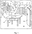
- FIG. 1 shows as an embodiment of a piece of furniture according to the invention a cabinet 10 which is placed in a room 20.
- the cabinet 10 is equipped with a control device 1 according to the invention.
- the cabinet 10 has a plurality of adjustable elements in the form of movable furniture parts 11, 12a - 12c. At the top of a downwardly hinged flap 11 is attached. To open and close the flap 11, this is equipped with a sensor-actuator combination 6. This can e.g. an electric drive with integrated protractor (not shown), with the example, different layers of the flap are adjustable and determinable.
- the cabinet 10 has, for each of the drawers 12a-12c, a sensor 5 each with which e.g. a closed position or e.g. several different positions of the respective drawer 12a - 12c can be seen.
- the furniture 10 is provided on each drawer 12a-12c, each with an actuator 4, with which the respective drawer 12a-12c can be moved.
- a control device 1 In the cabinet 10, a control device 1 according to the invention is housed, which has an example electronic control unit 2 and connecting means 3.
- the connection means 3 can provide one or more interfaces (not shown) with which the actuators 4 and sensors 5 can be connected to the control unit.
- the control unit 2 and the connection means 3 are connected to one another in such a way that the control unit 2 can exchange signals with connected components via the connection means 3.
- a connection 7 of the sensors 4 and the actuators 5 of the furniture 10 is in Fig.1 symbolically represented and can be provided with various known technologies, eg by means of radio links or eg by means of electrical connection lines.
- For connection with sensors 5 and actuators 4 in the furniture 10 can be used because of the short transmission paths in the furniture 10 comparatively simple interfaces, which have a short range and only over longer distances, eg more than 3 meters, a susceptibility.
- a ZigBee or eg a Z-wave interface can be used for a radio connection.
- a wired connection can be provided eg with one or more serial interfaces (not shown), in particular with a USB interface (USB: Universal Serial Bus).
- connection means 3 comprise one or more interfaces (not shown) with which connections 7 of the control device 1 with the room devices 13, 15, 16, 17 and 19 can be produced.
- the same interfaces can be used for these connections, which are available for connecting the sensors and actuators 4, 5, 6 of the furniture.
- one or more separate interfaces may be provided, which in particular may cover longer distances, e.g. from 10 to 100 meters, reliable support. This offers the advantage that it allows sensors and actuators 4, 5, 6 to be connected for signal transmission, which may occur outside the cabinet 10 and, if appropriate, at greater distances, e.g. on an opposite wall of a room or e.g. in another room of a building.
- an Ethernet interface (not shown) is suitable because of the widespread use of Ethernet technology.
- a special advantage of this communication technology in that this also versions are available, with which a communication via a power supply network, in particular a house power network is possible.
- the control device 1 is also provided and designed for the control of sensors and actuators 4, 5, 6, which are located outside of the furniture 10 and allow control of control devices 1,4, 16b, 18, 19b of room facilities.
- FIG. 1 For example, several room facilities are shown:
- a switching device 15 connected to a manual operation of the switching device 15 to the control unit 2 to transfer.
- a sensor 5 for example, signal a switching state or, for example, a change between switching states.
- a table 13 is connected to the control device 1.
- the control element of the table is a drawer 14, which can be extended and retracted by a sensor-actuator combination 6, which can be designed as an electric motor with position sensor.
- a lamp 16 the control member is an electric lighting element, is in communication with the control device 1.
- the lamp 16 is in this case via the actuator 4, which is used as e.g. a relay can be designed, controllable.
- a second cabinet 17 is placed at any point of the room 20, which has a plurality of drawers 18 as control organs.
- the drawers 18 are movable by means of sensor-actuator combinations 6 and connected to the control device 1.
- a room door 19 As an example of a room device, a room door 19 is shown.
- the door leaf 19b is controllable by means of a sensor-actuator combination 6.
- the control device 1 goes beyond the previous furniture controls in their functions, because it is not only for the control of parameters, in particular, for example, movable furniture parts 11, 12a - 12c, formed, but also on space facilities, for example, in their environment can control influence.
- various room devices 13, 15, 16, 17 and 19 not only vote on the possible uses of the furniture 10.
- the cabinets 10 and 17 can be arranged in the space 20 such that the opening of one of the drawers 12a-12c, 18 or the flap 11 leaves little movement space between the cabinets 10 and 17.
- the control device 1 may be configurable to block, for example, an opening on the cabinet 10 when the cabinet 17 is already open and, conversely, to block opening of the cabinet 17 when the cabinet 10 is already open.
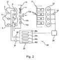
- the example of this frame condition serves as a starting point for an example of an in FIG. 2 partial configuration 29 of the control device 1.
- the sensors and actuators 4, 5, 6 on the one hand of the cabinet 10 and on the other hand of the cabinet 17 can be configured to two control groups: for example a first control group 21 for the cabinet 10 and a second control group 22 for the cabinet 17.
- Each of the sensor-actuator combinations 6 in the cabinet 17 may receive signals 23 e.g. upon actuation of one of the drawers 18 to the control device 11 transmit.
- the signals 23 of the individual sensor-actuator combinations 6 of the cabinet 17 for a trigger condition 24 may be coupled to each other by a logical OR operation such that an operation to open the cabinet 17 at one of the drawers 18 causes the trigger condition 24 is satisfied.
- the triggering condition 24 may be associated with a control function 25 that is linked to the first control group 21.
- the control function 25 may be configured such that opening one of the drawers 18 results in closure of the flap 11 and drawers 12a-12c.
- control functions 26a-26d can be called up with the control function 25 for the triggering condition 24, which are provided individually for controlling closing movements of one of the drawers 12a-12c or the flap 11, respectively.
- each control function 26a-26d may be designed to query one or more data 27 on the opening state of a drawer 12a-12c or flap 11 from a sensor 5, 6, and one or more signals 28 for an opened furniture part 12a-12c, 11 to send the appropriate actuator for a closing movement.
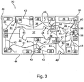
- FIG. 3 is shown schematically and not to scale an apartment 30 with several rooms 31 - 37, wherein in each room 31 - 37 each one inventive furniture 38 is located.
- the furniture 38 in the room 31 differs from that of the other rooms 32-37 in that the control device 42 is superior to the control devices 1 in the furniture 38 of the remaining rooms 32-37.
- the control devices 1 and 42 are provided in the respective rooms 31-37 for controlling the respective furniture 38 and room facilities 39 connected thereto.
- Several connections of sensors and actuators 4, 5, 6 of a room device 39 can be represented symbolically by a connecting line 43.
- Several different connections 43 between the control devices 1, 42 and room devices 39 can each be designed differently, e.g. wired and e.g. wireless. If a connection element (not shown) for a room device 39 with respect to e.g. the transmission range and e.g. the susceptibility is formed, the control device 1 can be e.g. of the room 33 with a room 39 of e.g. connect adjacent room 32.
- all control devices 1 are connected for communication with the control device 42, with, for example, a plurality of connections 41, for example, in sections, from one to the next Furniture 38 may be furnished.
- the control devices 1 and 42 may for example have a LAN interface (not shown), in particular an Ethernet interface (not shown).
- the controller 42 is provided with one or more configurable operating functions (not shown) as a superior control device.
- the operating functions for a superordinate mode of operation may e.g. be provided by appropriate programs (not shown), so that parent and simple control devices, in particular with respect to the control unit (not shown) and the connection means (not shown) do not differ.
- the higher-level control device 42 may also have hardware additions (not shown) to the control devices 1, allowing, for example, only an authorized person access to a configuration or configuration mode of the control device 42 and possibly to configurations of the control devices 1 connected to it.
- the operating functions of a higher-level control device can be designed to fulfill different tasks.
- one or more operational functions may be configured to selectively exchange, in particular configurable, signals, data, and information among a plurality of control devices, thereby transmitting them into e.g. in various rooms 31 - 37 to control the furniture 38 and room facilities 39 are available.
- a signal can be generated for transmission via the control device 42 to one or more predetermined control groups in control devices 1 in other rooms, eg room 32nd and 33, is to be transmitted.
- This offers the advantage of having a control over coordination of a plurality of furniture 38 or room devices 39 over a greater distance, for example, a maximum segment length of a communication network, is possible.
- furniture 38 and room furnishings 39 for example, in different rooms 31 - 37 of an apartment 30 coordinated controlled.
- the higher-level control device 42 is designed to set a power-saving mode.
- the higher-level control device 42 may be designed such that it sends via the connections 41 a message to one or more, and in particular to all control devices 1, which are thereby displaceable in their respective energy-saving mode.
- the control devices 1 and 42 may be equipped, for example, with a clock (not shown) or with a timer (not shown).
- the energy-saving mode can be achieved by means of e.g. the timer e.g.
- control device 1 or 42 which after expiry of a predetermined waiting time during which no operation of one of the furniture 38 or one of the room devices 39 has been signaled, a e.g. Supply voltage for sensors and actuators 4, 5, 6 decreases or completely shuts off.
- the higher-level control device 42 can also signal further events relating to several or all rooms 31 - 37 of an apartment to the control devices 1 by communication via the connections 41.
- Such further events may e.g. a power shutdown, e.g. a power failure, e.g. reaching a given intensity of solar radiation, e.g. reaching a given wind force and e.g. Be rain or hail.
- a power shutdown e.g. a power failure, e.g. reaching a given intensity of solar radiation, e.g. reaching a given wind force and e.g. Be rain or hail.
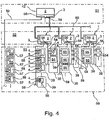
- FIG. 4 schematically shows in the form of a diagram, a control hierarchy 50, which is feasible with control devices 1 and 42 according to the invention in various designs or settings.
- the control hierarchy 50 is divided into different levels 51, 52 and 53.
- a superordinate level 51 is provided for processing tasks, events and conditions that relate to multiple areas, in particular rooms (not shown) of a building (not shown) or an entire building.
- a lower, local level 52 is provided for handling events and conditions relating to a single given area, particularly a room in a building.
- a furniture 38 according to the invention and at least one room device 39.
- a lowermost level 53 is associated with areas, in particular of furniture 38 and room facilities 39, in which events and conditions can be detected directly by sensors 5 and directly influenced by actuators 4.
- Most used in this level compounds 56, 58 and the sensors and actuators 4, 5, 6 are provided only for communication or signal transmission to a higher processing unit. Furthermore, the connections 56 and 58 provided for signal transmissions are of little or no suitability for communication in which sensors and actuators 4, 5, 6 exchange signals or data directly with one another.
- a control unit 2 and connection means 3 of a control device 1 or 42 according to the invention is always designed to provide connections and functions with which at least one parameter 54 of a furniture 38 and at least one control device 55 of a room device can be controlled.
- the control device 1, 42 for each parameter 54 and for each control element 55 each one or more functions (not shown), in particular control functions (not shown), with which either the respective parameter 54 or the respective control member 55 is independent of other connected parameters 54 and control bodies 55 controllable.
- the control device may preferably have one or more functions, in particular control functions, with which one of the parameters 54 can be controlled as a function of the state of one or more control organs.
Landscapes
- Engineering & Computer Science (AREA)
- General Engineering & Computer Science (AREA)
- Physics & Mathematics (AREA)
- General Physics & Mathematics (AREA)
- Automation & Control Theory (AREA)
- Power-Operated Mechanisms For Wings (AREA)
- Testing Of Short-Circuits, Discontinuities, Leakage, Or Incorrect Line Connections (AREA)
Claims (23)
- Dispositif (1, 42) pour contrôler un meuble (10, 38), comprenant une unité de contrôle (2) et des moyens de connexion (3) à l'aide desquels des actionneurs (4, 6) et des capteurs (5, 6) peuvent être connectés à l'unité de contrôle (2) pour une transmission de signaux afin de contrôler au moins un paramètre du meuble (10, 38), caractérisé en ce que les moyens de connexion (3) comprennent un élément de connexion (56) avec lequel peut être connecté pour une transmission de signaux un autre meuble (13, 17) muni d'une autre partie de meuble (14, 18) mobile, lequel peut être disposé indépendamment du meuble (10, 38) et à n'importe quelle distance de celui-ci, et en ce que l'unité de contrôle (2) présente une fonction de contrôle (25, 26a, 26b, 26c, 26d) à l'aide de laquelle un organe de contrôle (14, 16b, 18, 19b, 55) de l'autre meuble (13, 17) peut être contrôlé, le meuble (10, 38) et l'autre meuble (13, 17) étant contrôlables indépendamment l'un de l'autre.
- Dispositif (1, 42) selon la revendication 1, caractérisé en ce que l'unité de contrôle (2) est en mesure de contrôler les actionneurs (4, 6) et les capteurs (5, 6) pour un contrôle du mouvement d'une partie de meuble (11, 12a, 12b, 12c) mobile du meuble (10, 38).
- Dispositif (1, 42) selon l'une des revendications précédentes, caractérisé en ce qu'un ou plusieurs actionneurs (4, 6) et capteurs (5, 6) d'un autre meuble ou de plusieurs autres meubles peuvent être connectés aux moyens de connexion (3), en particulier à l'élément de connexion (56).
- Dispositif (1, 42) selon l'une des revendications précédentes, caractérisé en ce que l'unité de contrôle (2) présente au moins une fonction de contrôle (25, 26a, 26b, 26c, 26d) pour un des paramètres du meuble (10, 38) et l'organe de contrôle (14, 16b, 18, 19b, 55), laquelle peut être déclenchée par la réception d'un ou plusieurs signaux (23) via les moyens de connexion (3).
- Dispositif (1, 42) selon l'une des revendications précédentes, caractérisé en ce que l'unité de contrôle (2) est conçue de telle sorte qu'il est possible de configurer un groupe de contrôle (21, 22) auquel peuvent être affectés des capteurs (5, 6) et des actionneurs (4, 6) du paramètre et de l'organe de contrôle (14, 16b, 18, 19b, 55).
- Dispositif (1, 42) selon l'une des revendications précédentes, caractérisé en ce que l'unité de contrôle (2) est conçue de telle sorte qu'il est possible de configurer une affectation entre le groupe de contrôle (21, 22) et au moins une fonction de contrôle (25, 26a, 26b, 26c, 26d) qui coordonne au moins temporairement une opération ou un état de contrôle entre plusieurs membres du groupe de contrôle (21, 22).
- Dispositif (1, 42) selon l'une des revendications précédentes, caractérisé en ce qu'il est possible de configurer dans l'unité de contrôle (2) une condition de déclenchement (24) pour une fonction de contrôle (25, 26a, 26b, 26c, 26d) au moyen de laquelle un ou plusieurs signaux (23) peuvent être associés de telle manière que, lors de leur signalisation, l'unité de contrôle (2) lance l'exécution de la fonction de contrôle correspondante (25, 26a, 26b, 26c, 26d).
- Dispositif (1, 42) selon l'une des revendications précédentes, caractérisé en ce qu'une condition de déclenchement (24) peut être assignée à un groupe de contrôle (21, 22) dans l'unité de contrôle (2).
- Dispositif (1, 42) selon l'une des revendications précédentes, caractérisé en ce que les moyens de connexion (3) comprennent une unité de connexion avec laquelle le dispositif (1, 42) peut être connecté à un dispositif de contrôle (1, 42) pour communiquer via un réseau de communication (41, 60).
- Dispositif (1, 42) selon la revendication 9, caractérisé en ce que l'unité de connexion est conçue pour une communication de données par câbles.
- Dispositif (1, 42) selon l'une des revendications 9 ou 10, caractérisé en ce que l'unité de connexion est conçue pour la communication de données sans fil.
- Dispositif (1, 42) selon l'une des revendications 9 à 11, caractérisé en ce que l'unité de connexion est munie d'une connexion à un réseau d'alimentation électrique qui permet la communication de données via un réseau d'alimentation électrique connecté.
- Dispositif (1, 42) selon l'une des revendications précédentes, caractérisé en ce que l'unité de contrôle est conçue pour exécuter une fonction prédéterminée pour contrôler le paramètre et l'organe de contrôle (14, 16b, 18, 19b, 55) lorsqu'un signal prédéterminé est reçu d'un dispositif de contrôle supérieur.
- Dispositif (1, 42) selon l'une des revendications précédentes, caractérisé en ce qu'une information concernant l'emplacement du meuble peut être configurée dans l'unité de contrôle (2), l'unité de contrôle (2) évaluant l'information concernant l'emplacement lorsqu'une fonction pour contrôler le paramètre et l'élément de contrôle (14, 16b, 18, 19b, 55) est exécutée.
- Dispositif (1, 42) selon l'une des revendications précédentes, caractérisé en ce que le dispositif (1) peut être contrôlé par un dispositif de contrôle supérieur (42).
- Dispositif (1, 42) selon l'une des revendications précédentes, caractérisé en ce que le dispositif (42) est conçu de telle sorte qu'il est possible de contrôler un dispositif de contrôle subordonné (1) avec le dispositif (42).
- Dispositif (1, 42) selon l'une des revendications précédentes, caractérisé en ce que pour entraîner la partie de meuble mobile (11, 12a, 12b, 12c), il est prévu une unité d'entraînement en tant qu'actionneur (4, 6), et en ce que l'unité de contrôle (2) est conçue pour pouvoir connecter une autre unité d'entraînement d'une autre partie de meuble (14, 18) qui est montée mobile sur un autre meuble (13, 17) placé séparément dans l'espace, un contrôle du déplacement coordonné des deux parties de meuble mobiles (11, 12a, 12b, 12c, 14, 18) pouvant être réalisé avec l'unité de contrôle (2).
- Dispositif (1, 42) selon la revendication 13, caractérisé en ce que l'unité de contrôle est conçue pour pouvoir contrôler de manière découplée les uns des autres des mouvements de parties de meuble (11, 12a, 12b, 12c, 14, 18) de différents meubles (10, 13, 17, 38) qui peuvent être disposés séparément dans l'espace.
- Dispositif (1, 42) selon l'une des revendications 13 ou 14, caractérisé en ce que l'unité de contrôle (2) est conçue pour pouvoir contrôler de manière au moins partiellement couplée entre eux des mouvements de parties de meuble (11, 12a, 12b, 12c, 14, 18) de différents meubles (10, 13, 17, 38) qui peuvent être disposés séparément dans l'espace.
- Dispositif (1, 42) selon l'une des revendications précédentes, caractérisé en ce que l'unité de contrôle (2) est conçue de telle sorte qu'en actionnant une partie de meuble (11, 12a, 12b, 12c, 14, 18) mobile contrôlée par l'unité de contrôle (1), au moins une autre partie de meuble (11, 12a, 12b, 12c, 14, 18) mobile, qui est sous le contrôle du mouvement de l'unité de contrôle, peut être déplacée de manière temporairement couplée.
- Dispositif (1, 42) selon l'une des revendications précédentes, caractérisé en ce qu'une position de veille peut être mémorisée dans l'unité de contrôle (2) pour une partie de meuble (11, 12a, 12b, 12c, 14, 18) mobile connectée pour le contrôle du déplacement.
- Dispositif (1, 42) selon l'une des revendications précédentes, caractérisé en ce qu'un intervalle de temps peut être réglé dans l'unité de contrôle (2), après lequel une partie de meuble (11, 12a, 12b, 12c, 14, 18) qui est sous le contrôle du mouvement de l'unité de contrôle (2) est amenée en position de veille.
- Meubles (10, 38) avec un dispositif (1, 42) selon l'une des revendications précédentes.
Applications Claiming Priority (1)
| Application Number | Priority Date | Filing Date | Title |
|---|---|---|---|
| DE202012009566.8U DE202012009566U1 (de) | 2012-10-08 | 2012-10-08 | Vorrichtung zur Kontrolle eines Möbels |
Publications (3)
| Publication Number | Publication Date |
|---|---|
| EP2717105A2 EP2717105A2 (fr) | 2014-04-09 |
| EP2717105A3 EP2717105A3 (fr) | 2016-12-21 |
| EP2717105B1 true EP2717105B1 (fr) | 2019-06-12 |
Family
ID=49293426
Family Applications (1)
| Application Number | Title | Priority Date | Filing Date |
|---|---|---|---|
| EP13004710.3A Active EP2717105B1 (fr) | 2012-10-08 | 2013-09-27 | Dispositif de contrôle d'un meuble |
Country Status (2)
| Country | Link |
|---|---|
| EP (1) | EP2717105B1 (fr) |
| DE (1) | DE202012009566U1 (fr) |
Cited By (1)
| Publication number | Priority date | Publication date | Assignee | Title |
|---|---|---|---|---|
| EP3879173A1 (fr) * | 2020-03-11 | 2021-09-15 | Wilhelm Koch GmbH | Ensemble de composants à fonctionnement électrique |
Families Citing this family (1)
| Publication number | Priority date | Publication date | Assignee | Title |
|---|---|---|---|---|
| CN113734729B (zh) * | 2021-09-03 | 2023-09-08 | 河南帅太整体定制家居有限公司 | 一种家具智能移动平台 |
Family Cites Families (9)
| Publication number | Priority date | Publication date | Assignee | Title |
|---|---|---|---|---|
| DE19751329B4 (de) * | 1997-11-19 | 2015-05-21 | Trumpf Medizin Systeme Gmbh + Co. Kg | Zusatzmodul für einen Operationstisch und Operationstisch mit Zusatzmodul |
| DE10220866A1 (de) * | 2001-05-18 | 2002-11-28 | Huwil Werke Gmbh | Verfahren und Einrichtung zum automatischen Entriegeln und Verriegeln von Möbelschlössern |
| AT414004B (de) * | 2004-02-19 | 2006-08-15 | Blum Gmbh Julius | Möbel |
| DE102006002887A1 (de) * | 2006-01-20 | 2007-08-09 | Logicdata Electronic & Software Entwicklungs Gmbh | Elektrisch verstellbares Möbelstück und Verfahren zum Warten eines elektrisch verstellbaren Möbelstücks |
| DE102006012060A1 (de) * | 2006-03-08 | 2007-09-13 | Fraunhofer-Gesellschaft zur Förderung der angewandten Forschung e.V. | Mittel und System für intelligente Umgebungen |
| DE202006006189U1 (de) * | 2006-04-18 | 2007-08-30 | Paul Hettich Gmbh & Co. Kg | Antriebseinrichtung für bewegbare Möbelteile |
| US8926535B2 (en) * | 2006-09-14 | 2015-01-06 | Martin B. Rawls-Meehan | Adjustable bed position control |
| DE102008044848B4 (de) * | 2008-08-28 | 2020-02-27 | Logicdata Electronic & Software Entwicklungs Gmbh | Möbelsystem und Verfahren zum Betreiben eines solchen |
| AT13324U1 (de) * | 2010-05-10 | 2013-10-15 | Blum Gmbh Julius | Anordnung von wenigstens zwei Möbeln und einer Sicherungsvorrichtung für einen Möbelantrieb |
-
2012
- 2012-10-08 DE DE202012009566.8U patent/DE202012009566U1/de not_active Expired - Lifetime
-
2013
- 2013-09-27 EP EP13004710.3A patent/EP2717105B1/fr active Active
Non-Patent Citations (1)
| Title |
|---|
| None * |
Cited By (1)
| Publication number | Priority date | Publication date | Assignee | Title |
|---|---|---|---|---|
| EP3879173A1 (fr) * | 2020-03-11 | 2021-09-15 | Wilhelm Koch GmbH | Ensemble de composants à fonctionnement électrique |
Also Published As
| Publication number | Publication date |
|---|---|
| EP2717105A3 (fr) | 2016-12-21 |
| EP2717105A2 (fr) | 2014-04-09 |
| DE202012009566U1 (de) | 2014-01-09 |
Similar Documents
| Publication | Publication Date | Title |
|---|---|---|
| EP2561413A1 (fr) | Système immotique | |
| EP1926069A2 (fr) | Télécommande radio | |
| EP1936453B1 (fr) | Dispositif domotique | |
| EP3416337B1 (fr) | Dispositif d'automatisation d'une maison ou d'un bâtiment | |
| EP2717105B1 (fr) | Dispositif de contrôle d'un meuble | |
| CH707465A2 (de) | Gateway für eine Gebäude- oder Einfriedungsabschlussantriebsvorrichtung sowie Verwendung derselben. | |
| EP2424075B1 (fr) | Participants pour un système d'installation de bâtiment et système d'installation de bâtiment doté de tels participants | |
| AT504670B1 (de) | Verfahren zum betreiben einer drahtlosen kommunikationsverbindung zwischen einem mobilen handbediengerät und einer maschinensteuerung sowie entsprechende systemkomponenten | |
| EP2796651B1 (fr) | Système d'un bâtiment doté de plusieurs dispositifs de fermeture | |
| DE102007040425B4 (de) | Elektronisches Gerät, Umrichter, Verfahren zur Adressierung und Anlage | |
| EP2762667B1 (fr) | Système d'entraînement et méthode de fonctionnement d'un système d'entraînement | |
| DE202011110079U1 (de) | System zur Ansteuerung eines Thermostatventils | |
| EP2031315A2 (fr) | Dispositif d'aspiration de fumée et de chaleur et/ou d'aération comprenant des appareils d'aspiration de fumée et de chaleur dotés d'entraînements motorisés | |
| DE10034774A1 (de) | Fernsteuereinrichtung für Antriebe von Schließvorrichtungen für Gebäudeöffnungen | |
| EP1734636A2 (fr) | Boîtier de commutation | |
| DE69521775T2 (de) | Steuergerät für aktive elektrische Lasten, wie Rolläden, Beleuchtung oder dergleichen | |
| EP2447795B1 (fr) | Système de commande de dispositifs de fonctionnement dans des bâtiments | |
| EP0874343A2 (fr) | Système pour une opération confortable, pour la surveillance et pour un échange de données | |
| DE202018102478U1 (de) | Gebäude- oder Einfriedungsabschlussantriebsperipheriegerät und -system | |
| EP4162463B1 (fr) | Dispositif pour commander au moins un élément de meuble pouvant être entraîné ou déplacé électriquement | |
| AT523888B1 (de) | Verfahren zur Einrichtung wenigstens eines Möbelantriebes | |
| EP3664304B1 (fr) | Entrée et sortie de données et transport de données par l'intermédiaire d'une conduite d'alimentation électrique des systèmes d'éclairage | |
| EP4162462A1 (fr) | Dispositif pour recevoir des signaux par l'intermédiaire d'au moins un élément de meuble pouvant être entraîné ou déplacé électriquement | |
| EP3457561B1 (fr) | Moteur avec un convertisseur de fréquence et un commutateur destiné à commuter une tension alternative monophasée | |
| EP4614948A1 (fr) | Dispositif de mise en service, système de mise en service et procédé de mise en service d'un système de sécurité d'accès |
Legal Events
| Date | Code | Title | Description |
|---|---|---|---|
| PUAI | Public reference made under article 153(3) epc to a published international application that has entered the european phase |
Free format text: ORIGINAL CODE: 0009012 |
|
| AK | Designated contracting states |
Kind code of ref document: A2 Designated state(s): AL AT BE BG CH CY CZ DE DK EE ES FI FR GB GR HR HU IE IS IT LI LT LU LV MC MK MT NL NO PL PT RO RS SE SI SK SM TR |
|
| AX | Request for extension of the european patent |
Extension state: BA ME |
|
| PUAL | Search report despatched |
Free format text: ORIGINAL CODE: 0009013 |
|
| AK | Designated contracting states |
Kind code of ref document: A3 Designated state(s): AL AT BE BG CH CY CZ DE DK EE ES FI FR GB GR HR HU IE IS IT LI LT LU LV MC MK MT NL NO PL PT RO RS SE SI SK SM TR |
|
| AX | Request for extension of the european patent |
Extension state: BA ME |
|
| RIC1 | Information provided on ipc code assigned before grant |
Ipc: G05B 15/02 20060101AFI20161115BHEP Ipc: A47B 96/00 20060101ALI20161115BHEP Ipc: A47B 88/04 20060101ALI20161115BHEP |
|
| STAA | Information on the status of an ep patent application or granted ep patent |
Free format text: STATUS: REQUEST FOR EXAMINATION WAS MADE |
|
| 17P | Request for examination filed |
Effective date: 20170529 |
|
| RBV | Designated contracting states (corrected) |
Designated state(s): AL AT BE BG CH CY CZ DE DK EE ES FI FR GB GR HR HU IE IS IT LI LT LU LV MC MK MT NL NO PL PT RO RS SE SI SK SM TR |
|
| GRAP | Despatch of communication of intention to grant a patent |
Free format text: ORIGINAL CODE: EPIDOSNIGR1 |
|
| STAA | Information on the status of an ep patent application or granted ep patent |
Free format text: STATUS: GRANT OF PATENT IS INTENDED |
|
| RIC1 | Information provided on ipc code assigned before grant |
Ipc: A47B 88/457 20170101ALI20181205BHEP Ipc: G05B 15/02 20060101AFI20181205BHEP Ipc: A47B 96/00 20060101ALI20181205BHEP |
|
| INTG | Intention to grant announced |
Effective date: 20190104 |
|
| RIC1 | Information provided on ipc code assigned before grant |
Ipc: A47B 88/457 20170101ALI20181205BHEP Ipc: A47B 96/00 20060101ALI20181205BHEP Ipc: G05B 15/02 20060101AFI20181205BHEP |
|
| GRAS | Grant fee paid |
Free format text: ORIGINAL CODE: EPIDOSNIGR3 |
|
| GRAA | (expected) grant |
Free format text: ORIGINAL CODE: 0009210 |
|
| STAA | Information on the status of an ep patent application or granted ep patent |
Free format text: STATUS: THE PATENT HAS BEEN GRANTED |
|
| AK | Designated contracting states |
Kind code of ref document: B1 Designated state(s): AL AT BE BG CH CY CZ DE DK EE ES FI FR GB GR HR HU IE IS IT LI LT LU LV MC MK MT NL NO PL PT RO RS SE SI SK SM TR |
|
| REG | Reference to a national code |
Ref country code: GB Ref legal event code: FG4D Free format text: NOT ENGLISH |
|
| REG | Reference to a national code |
Ref country code: CH Ref legal event code: EP |
|
| REG | Reference to a national code |
Ref country code: AT Ref legal event code: REF Ref document number: 1143372 Country of ref document: AT Kind code of ref document: T Effective date: 20190615 |
|
| REG | Reference to a national code |
Ref country code: DE Ref legal event code: R096 Ref document number: 502013012965 Country of ref document: DE |
|
| REG | Reference to a national code |
Ref country code: IE Ref legal event code: FG4D Free format text: LANGUAGE OF EP DOCUMENT: GERMAN |
|
| REG | Reference to a national code |
Ref country code: NL Ref legal event code: MP Effective date: 20190612 |
|
| REG | Reference to a national code |
Ref country code: LT Ref legal event code: MG4D |
|
| PG25 | Lapsed in a contracting state [announced via postgrant information from national office to epo] |
Ref country code: NO Free format text: LAPSE BECAUSE OF FAILURE TO SUBMIT A TRANSLATION OF THE DESCRIPTION OR TO PAY THE FEE WITHIN THE PRESCRIBED TIME-LIMIT Effective date: 20190912 Ref country code: LT Free format text: LAPSE BECAUSE OF FAILURE TO SUBMIT A TRANSLATION OF THE DESCRIPTION OR TO PAY THE FEE WITHIN THE PRESCRIBED TIME-LIMIT Effective date: 20190612 Ref country code: FI Free format text: LAPSE BECAUSE OF FAILURE TO SUBMIT A TRANSLATION OF THE DESCRIPTION OR TO PAY THE FEE WITHIN THE PRESCRIBED TIME-LIMIT Effective date: 20190612 Ref country code: HR Free format text: LAPSE BECAUSE OF FAILURE TO SUBMIT A TRANSLATION OF THE DESCRIPTION OR TO PAY THE FEE WITHIN THE PRESCRIBED TIME-LIMIT Effective date: 20190612 Ref country code: SE Free format text: LAPSE BECAUSE OF FAILURE TO SUBMIT A TRANSLATION OF THE DESCRIPTION OR TO PAY THE FEE WITHIN THE PRESCRIBED TIME-LIMIT Effective date: 20190612 Ref country code: AL Free format text: LAPSE BECAUSE OF FAILURE TO SUBMIT A TRANSLATION OF THE DESCRIPTION OR TO PAY THE FEE WITHIN THE PRESCRIBED TIME-LIMIT Effective date: 20190612 Ref country code: ES Free format text: LAPSE BECAUSE OF FAILURE TO SUBMIT A TRANSLATION OF THE DESCRIPTION OR TO PAY THE FEE WITHIN THE PRESCRIBED TIME-LIMIT Effective date: 20190612 |
|
| PG25 | Lapsed in a contracting state [announced via postgrant information from national office to epo] |
Ref country code: BG Free format text: LAPSE BECAUSE OF FAILURE TO SUBMIT A TRANSLATION OF THE DESCRIPTION OR TO PAY THE FEE WITHIN THE PRESCRIBED TIME-LIMIT Effective date: 20190912 Ref country code: RS Free format text: LAPSE BECAUSE OF FAILURE TO SUBMIT A TRANSLATION OF THE DESCRIPTION OR TO PAY THE FEE WITHIN THE PRESCRIBED TIME-LIMIT Effective date: 20190612 Ref country code: LV Free format text: LAPSE BECAUSE OF FAILURE TO SUBMIT A TRANSLATION OF THE DESCRIPTION OR TO PAY THE FEE WITHIN THE PRESCRIBED TIME-LIMIT Effective date: 20190612 Ref country code: GR Free format text: LAPSE BECAUSE OF FAILURE TO SUBMIT A TRANSLATION OF THE DESCRIPTION OR TO PAY THE FEE WITHIN THE PRESCRIBED TIME-LIMIT Effective date: 20190913 |
|
| PG25 | Lapsed in a contracting state [announced via postgrant information from national office to epo] |
Ref country code: SK Free format text: LAPSE BECAUSE OF FAILURE TO SUBMIT A TRANSLATION OF THE DESCRIPTION OR TO PAY THE FEE WITHIN THE PRESCRIBED TIME-LIMIT Effective date: 20190612 Ref country code: EE Free format text: LAPSE BECAUSE OF FAILURE TO SUBMIT A TRANSLATION OF THE DESCRIPTION OR TO PAY THE FEE WITHIN THE PRESCRIBED TIME-LIMIT Effective date: 20190612 Ref country code: PT Free format text: LAPSE BECAUSE OF FAILURE TO SUBMIT A TRANSLATION OF THE DESCRIPTION OR TO PAY THE FEE WITHIN THE PRESCRIBED TIME-LIMIT Effective date: 20191014 Ref country code: NL Free format text: LAPSE BECAUSE OF FAILURE TO SUBMIT A TRANSLATION OF THE DESCRIPTION OR TO PAY THE FEE WITHIN THE PRESCRIBED TIME-LIMIT Effective date: 20190612 Ref country code: RO Free format text: LAPSE BECAUSE OF FAILURE TO SUBMIT A TRANSLATION OF THE DESCRIPTION OR TO PAY THE FEE WITHIN THE PRESCRIBED TIME-LIMIT Effective date: 20190612 Ref country code: CZ Free format text: LAPSE BECAUSE OF FAILURE TO SUBMIT A TRANSLATION OF THE DESCRIPTION OR TO PAY THE FEE WITHIN THE PRESCRIBED TIME-LIMIT Effective date: 20190612 |
|
| PG25 | Lapsed in a contracting state [announced via postgrant information from national office to epo] |
Ref country code: IS Free format text: LAPSE BECAUSE OF FAILURE TO SUBMIT A TRANSLATION OF THE DESCRIPTION OR TO PAY THE FEE WITHIN THE PRESCRIBED TIME-LIMIT Effective date: 20191012 Ref country code: SM Free format text: LAPSE BECAUSE OF FAILURE TO SUBMIT A TRANSLATION OF THE DESCRIPTION OR TO PAY THE FEE WITHIN THE PRESCRIBED TIME-LIMIT Effective date: 20190612 |
|
| REG | Reference to a national code |
Ref country code: DE Ref legal event code: R097 Ref document number: 502013012965 Country of ref document: DE |
|
| PG25 | Lapsed in a contracting state [announced via postgrant information from national office to epo] |
Ref country code: TR Free format text: LAPSE BECAUSE OF FAILURE TO SUBMIT A TRANSLATION OF THE DESCRIPTION OR TO PAY THE FEE WITHIN THE PRESCRIBED TIME-LIMIT Effective date: 20190612 |
|
| PLBE | No opposition filed within time limit |
Free format text: ORIGINAL CODE: 0009261 |
|
| STAA | Information on the status of an ep patent application or granted ep patent |
Free format text: STATUS: NO OPPOSITION FILED WITHIN TIME LIMIT |
|
| PG25 | Lapsed in a contracting state [announced via postgrant information from national office to epo] |
Ref country code: PL Free format text: LAPSE BECAUSE OF FAILURE TO SUBMIT A TRANSLATION OF THE DESCRIPTION OR TO PAY THE FEE WITHIN THE PRESCRIBED TIME-LIMIT Effective date: 20190612 Ref country code: DK Free format text: LAPSE BECAUSE OF FAILURE TO SUBMIT A TRANSLATION OF THE DESCRIPTION OR TO PAY THE FEE WITHIN THE PRESCRIBED TIME-LIMIT Effective date: 20190612 |
|
| 26N | No opposition filed |
Effective date: 20200313 |
|
| PG25 | Lapsed in a contracting state [announced via postgrant information from national office to epo] |
Ref country code: SI Free format text: LAPSE BECAUSE OF FAILURE TO SUBMIT A TRANSLATION OF THE DESCRIPTION OR TO PAY THE FEE WITHIN THE PRESCRIBED TIME-LIMIT Effective date: 20190612 Ref country code: IS Free format text: LAPSE BECAUSE OF FAILURE TO SUBMIT A TRANSLATION OF THE DESCRIPTION OR TO PAY THE FEE WITHIN THE PRESCRIBED TIME-LIMIT Effective date: 20200224 Ref country code: MC Free format text: LAPSE BECAUSE OF FAILURE TO SUBMIT A TRANSLATION OF THE DESCRIPTION OR TO PAY THE FEE WITHIN THE PRESCRIBED TIME-LIMIT Effective date: 20190612 |
|
| REG | Reference to a national code |
Ref country code: CH Ref legal event code: PL |
|
| PG2D | Information on lapse in contracting state deleted |
Ref country code: IS |
|
| PG25 | Lapsed in a contracting state [announced via postgrant information from national office to epo] |
Ref country code: CH Free format text: LAPSE BECAUSE OF NON-PAYMENT OF DUE FEES Effective date: 20190930 Ref country code: IE Free format text: LAPSE BECAUSE OF NON-PAYMENT OF DUE FEES Effective date: 20190927 Ref country code: LU Free format text: LAPSE BECAUSE OF NON-PAYMENT OF DUE FEES Effective date: 20190927 Ref country code: LI Free format text: LAPSE BECAUSE OF NON-PAYMENT OF DUE FEES Effective date: 20190930 |
|
| REG | Reference to a national code |
Ref country code: BE Ref legal event code: MM Effective date: 20190930 |
|
| PG25 | Lapsed in a contracting state [announced via postgrant information from national office to epo] |
Ref country code: BE Free format text: LAPSE BECAUSE OF NON-PAYMENT OF DUE FEES Effective date: 20190930 |
|
| GBPC | Gb: european patent ceased through non-payment of renewal fee |
Effective date: 20190927 |
|
| PG25 | Lapsed in a contracting state [announced via postgrant information from national office to epo] |
Ref country code: FR Free format text: LAPSE BECAUSE OF NON-PAYMENT OF DUE FEES Effective date: 20190930 Ref country code: GB Free format text: LAPSE BECAUSE OF NON-PAYMENT OF DUE FEES Effective date: 20190927 |
|
| PG25 | Lapsed in a contracting state [announced via postgrant information from national office to epo] |
Ref country code: CY Free format text: LAPSE BECAUSE OF FAILURE TO SUBMIT A TRANSLATION OF THE DESCRIPTION OR TO PAY THE FEE WITHIN THE PRESCRIBED TIME-LIMIT Effective date: 20190612 |
|
| PG25 | Lapsed in a contracting state [announced via postgrant information from national office to epo] |
Ref country code: HU Free format text: LAPSE BECAUSE OF FAILURE TO SUBMIT A TRANSLATION OF THE DESCRIPTION OR TO PAY THE FEE WITHIN THE PRESCRIBED TIME-LIMIT; INVALID AB INITIO Effective date: 20130927 Ref country code: MT Free format text: LAPSE BECAUSE OF FAILURE TO SUBMIT A TRANSLATION OF THE DESCRIPTION OR TO PAY THE FEE WITHIN THE PRESCRIBED TIME-LIMIT Effective date: 20190612 |
|
| PGFP | Annual fee paid to national office [announced via postgrant information from national office to epo] |
Ref country code: IT Payment date: 20210817 Year of fee payment: 9 |
|
| PG25 | Lapsed in a contracting state [announced via postgrant information from national office to epo] |
Ref country code: MK Free format text: LAPSE BECAUSE OF FAILURE TO SUBMIT A TRANSLATION OF THE DESCRIPTION OR TO PAY THE FEE WITHIN THE PRESCRIBED TIME-LIMIT Effective date: 20190612 |
|
| PG25 | Lapsed in a contracting state [announced via postgrant information from national office to epo] |
Ref country code: IT Free format text: LAPSE BECAUSE OF NON-PAYMENT OF DUE FEES Effective date: 20220927 |
|
| REG | Reference to a national code |
Ref country code: DE Ref legal event code: R082 Ref document number: 502013012965 Country of ref document: DE Representative=s name: RAVENSPAT PATENTANWAELTE PARTNERSCHAFT MBB, DE |
|
| PGFP | Annual fee paid to national office [announced via postgrant information from national office to epo] |
Ref country code: DE Payment date: 20250917 Year of fee payment: 13 |
|
| PGFP | Annual fee paid to national office [announced via postgrant information from national office to epo] |
Ref country code: AT Payment date: 20250919 Year of fee payment: 13 |