EP2717263B1 - Verfahren, Vorrichtung und Computerprogrammprodukt zur kategorischen räumlichen Analyse-Synthese des Spektrums eines Mehrkanal-Audiosignals - Google Patents
Verfahren, Vorrichtung und Computerprogrammprodukt zur kategorischen räumlichen Analyse-Synthese des Spektrums eines Mehrkanal-Audiosignals Download PDFInfo
- Publication number
- EP2717263B1 EP2717263B1 EP13184236.1A EP13184236A EP2717263B1 EP 2717263 B1 EP2717263 B1 EP 2717263B1 EP 13184236 A EP13184236 A EP 13184236A EP 2717263 B1 EP2717263 B1 EP 2717263B1
- Authority
- EP
- European Patent Office
- Prior art keywords
- spectrum
- bands
- tonal
- signal
- synthesis
- Prior art date
- Legal status (The legal status is an assumption and is not a legal conclusion. Google has not performed a legal analysis and makes no representation as to the accuracy of the status listed.)
- Not-in-force
Links
Images




Classifications
-
- H—ELECTRICITY
- H04—ELECTRIC COMMUNICATION TECHNIQUE
- H04R—LOUDSPEAKERS, MICROPHONES, GRAMOPHONE PICK-UPS OR LIKE ACOUSTIC ELECTROMECHANICAL TRANSDUCERS; ELECTRIC HEARING AIDS; PUBLIC ADDRESS SYSTEMS
- H04R5/00—Stereophonic arrangements
- H04R5/04—Circuit arrangements, e.g. for selective connection of amplifier inputs/outputs to loudspeakers, for loudspeaker detection, or for adaptation of settings to personal preferences or hearing impairments
-
- G—PHYSICS
- G10—MUSICAL INSTRUMENTS; ACOUSTICS
- G10L—SPEECH ANALYSIS TECHNIQUES OR SPEECH SYNTHESIS; SPEECH RECOGNITION; SPEECH OR VOICE PROCESSING TECHNIQUES; SPEECH OR AUDIO CODING OR DECODING
- G10L19/00—Speech or audio signals analysis-synthesis techniques for redundancy reduction, e.g. in vocoders; Coding or decoding of speech or audio signals, using source filter models or psychoacoustic analysis
- G10L19/008—Multichannel audio signal coding or decoding using interchannel correlation to reduce redundancy, e.g. joint-stereo, intensity-coding or matrixing
-
- G—PHYSICS
- G10—MUSICAL INSTRUMENTS; ACOUSTICS
- G10L—SPEECH ANALYSIS TECHNIQUES OR SPEECH SYNTHESIS; SPEECH RECOGNITION; SPEECH OR VOICE PROCESSING TECHNIQUES; SPEECH OR AUDIO CODING OR DECODING
- G10L19/00—Speech or audio signals analysis-synthesis techniques for redundancy reduction, e.g. in vocoders; Coding or decoding of speech or audio signals, using source filter models or psychoacoustic analysis
- G10L19/02—Speech or audio signals analysis-synthesis techniques for redundancy reduction, e.g. in vocoders; Coding or decoding of speech or audio signals, using source filter models or psychoacoustic analysis using spectral analysis, e.g. transform vocoders or subband vocoders
-
- G—PHYSICS
- G10—MUSICAL INSTRUMENTS; ACOUSTICS
- G10L—SPEECH ANALYSIS TECHNIQUES OR SPEECH SYNTHESIS; SPEECH RECOGNITION; SPEECH OR VOICE PROCESSING TECHNIQUES; SPEECH OR AUDIO CODING OR DECODING
- G10L19/00—Speech or audio signals analysis-synthesis techniques for redundancy reduction, e.g. in vocoders; Coding or decoding of speech or audio signals, using source filter models or psychoacoustic analysis
- G10L19/04—Speech or audio signals analysis-synthesis techniques for redundancy reduction, e.g. in vocoders; Coding or decoding of speech or audio signals, using source filter models or psychoacoustic analysis using predictive techniques
- G10L19/16—Vocoder architecture
- G10L19/18—Vocoders using multiple modes
- G10L19/20—Vocoders using multiple modes using sound class specific coding, hybrid encoders or object based coding
-
- H—ELECTRICITY
- H04—ELECTRIC COMMUNICATION TECHNIQUE
- H04S—STEREOPHONIC SYSTEMS
- H04S7/00—Indicating arrangements; Control arrangements, e.g. balance control
- H04S7/30—Control circuits for electronic adaptation of the sound field
-
- H—ELECTRICITY
- H04—ELECTRIC COMMUNICATION TECHNIQUE
- H04S—STEREOPHONIC SYSTEMS
- H04S2400/00—Details of stereophonic systems covered by H04S but not provided for in its groups
- H04S2400/01—Multi-channel, i.e. more than two input channels, sound reproduction with two speakers wherein the multi-channel information is substantially preserved
-
- H—ELECTRICITY
- H04—ELECTRIC COMMUNICATION TECHNIQUE
- H04S—STEREOPHONIC SYSTEMS
- H04S2420/00—Techniques used stereophonic systems covered by H04S but not provided for in its groups
- H04S2420/01—Enhancing the perception of the sound image or of the spatial distribution using head related transfer functions [HRTF's] or equivalents thereof, e.g. interaural time difference [ITD] or interaural level difference [ILD]
Definitions
- An example embodiment of the present invention relates generally to analysis and synthesis of multichannel signals.
- a binaural audio signal from a multichannel signal that are based on a fixed filterbank structure.
- Some other variations include using a non-uniform filterbank structure or structures based on alternative auditory scales.
- binaural signals can be satisfactorily generated, such methods are not suitable to manipulating the components present within the audio signal.
- the spatial analysis of a multichannel signal is performed on a single band which may contain contributions from multiple auditory sources (i.e. a multipitch signal could have very closely spaced harmonics). It may not be possible to get the spatial distribution of the different components present in the entire spectrum of the signal. Performance of pitch synchronous analysis of such signals is restricted to signals containing a single pitch, since multipitch signals tend to be difficult to analyze and require complex algorithms.
- Performance of tone detection methods can suffer due to noise.
- Some tonal component detection methods may require estimating approximate pitch in a time domain and then refining the spectral peak estimate in a spectral domain. In such scenarios, performance of pitch detection can degrade in the presence of multiple periodicities in the signal.
- Many techniques are based on distance measures or correlation based or geometrical and search based methods to detect the tones and require comparison with a threshold for some stage of decision making. Thresholds on spectral mismatches are prone to errors in the presence of noise and also need normalization based on signal strengths.
- PCT publication WO 2007/028250 A2 discloses a binaural speech enhancement system arranged to provide binaural output signals based on binaural sets of spatially distinct input signals, wherein acoustic cues are extracted by auditory scene analysis and used to segregate speech components from noise components in the input signals and to enhance the speech components in the binaural output signals.
- a method, apparatus and computer program product are therefore provided according to an example embodiment of the present invention in order to perform categorical analysis and synthesis of a multichannel signal to synthesize binaural signals and extract, separate, and manipulate components within the audio scene of the multichannel signal that were captured through multichannel audio means.
- a method at least includes receiving a multichannel signal, computing the spectrum for the multichannel signal, and generating a band structure for the spectrum by determining which bands of the spectrum are tonal and which bands of the spectrum are non-tonal.
- the method of this embodiment also includes performing spatial analysis on only the bands of the spectrum determined as tonal by determining a delay that maximizes the correlation between a first channel and a second channel of the multichannel signal, transforming the delay into an angle in azimuthal plane and using the angle to determine the spatial location of a source signal, performing source filtering on the bands of the spectrum determined as tonal with head related transfer function filters, and performing synthesis on components of the source filtered tonal bands components by applying an inverse Discrete Fourier transform and applying overlap and add synthesis.
- the method may further include determining the tonality of bands within the spectrum on only one channel in the multichannel signal. In some embodiments, determining the tonality of bands within the spectrum comprises determining if the band is tonal or non-tonal. In some embodiments, the width of the bands may be variable. For example one of the choices for widths of the bands may be ⁇ 29.6 Hz, 41 Hz, 52.75 Hz, 64.5 Hz, 76 Hz ⁇ .
- the method may further include a tonality determination of bands in the spectrum based on statistical goodness of fit tests.
- the tonality determination comprises comparing a spectral component distribution in a band to an expected spectral component distribution.
- the expected spectral component distribution may be generated by a sinusoid.
- comparison of the spectral component distributions may include using a test of goodness of fit, such as a chi-square test.
- the method may further include generating a band structure for the spectrum by computing upper and lower limits of tonal and non-tonal bands.
- generating a band structure for the spectrum may include consolidating multiple continuous tonal bands into a single band.
- spatial analysis of the bands may include determining the spatial location of a source.
- the output signal may be an individual source in an audio scene of the multichannel signal, a binaural signal, source relocation within an audio scene of the multichannel signal, or directional component separation.
- a computer program product when executed causes an apparatus to perform a method as described herein.
- an apparatus in another embodiment, includes at least means for receiving a multichannel signal, means for computing the spectrum for the multichannel signal, and means for generating a band structure for the spectrum by determining which bands of the spectrum are tonal and which bands of the spectrum are non-tonal.
- the apparatus of this embodiment also includes means for performing spatial analysis on only the bands of the spectrum determined as tonal by determining a delay that maximizes the correlation between a first channel and a second channel of the multichannel signal, transforming the delay into an angle in azimuthal plane and using the angle to determine the spatial location of a source signal, means for performing source filtering on bands of the spectrum determined as tonal with head related transfer function filters and means for performing synthesis on components of the source filtered tonal bands by applying an inverse Discrete Fourier transform and applying overlap and add synthesis.
- circuitry refers to (a) hardware-only circuit implementations (e.g., implementations in analog circuitry and/or digital circuitry); (b) combinations of circuits and computer program product(s) comprising software and/or firmware instructions stored on one or more computer readable memories that work together to cause an apparatus to perform one or more functions described herein; and (c) circuits, such as, for example, a microprocessor(s) or a portion of a microprocessor(s), that require software or firmware for operation even if the software or firmware is not physically present.
- This definition of 'circuitry' applies to all uses of this term herein, including in any claims.
- the term 'circuitry' also includes an implementation comprising one or more processors and/or portion(s) thereof and accompanying software and/or firmware.
- the term 'circuitry' as used herein also includes, for example, a baseband integrated circuit or applications processor integrated circuit for a mobile phone or a similar integrated circuit in a server, a cellular network device, other network device, and/or other computing device.
- a method, apparatus and computer program product are provided in accordance with an example embodiment of the present invention to perform categorical analysis and synthesis of a multichannel signal to synthesize binaural signals and extract, separate, and manipulate components within the audio scene of the multichannel signal that were captured through multichannel audio means.
- Embodiments of the present invention may perform analysis and synthesis of a multichannel signal to synthesize binaural signals and extract, separate, and manipulate components within the audio scene of the multichannel signal that were captured through multichannel audio means.
- Embodiments of the present invention do not require pitch estimation in time and frequency domains.
- the embodiments perform spatial analysis categorically on the spectrum rather than on the entire spectrum. The categorization is based on a tonal nature of bands within the spectrum.
- the categorical analysis-synthesis enables various functions such as source separation, source manipulation, and binaural synthesis.
- spatial cues for the multichannel signal are captured by analyzing fewer components (namely tonal components) in the spectrum, which are more relevant for carrying information about the direction. Therefore, operations are more computationally efficient since only the bands specific to tonal regions need analysis and/or synthesis. Additionally, the tonality computation does not require pitch detection and is also suitable for use with multipitch signals.
- FIG. 1 For if a signal is a combination of harmonic and non-harmonic components, spectral peaks can be reliably estimated.
- the tonality detection operation is flexible enough to allow gradual tuning by changing its parameters.
- Some embodiments of the present invention may use a statistical goodness of fit method for identifying tonality in the spectrum.
- the sum of two complex exponentials with the same frequency of oscillation would give two lines; one at +ve and one at -ve frequency, 0.5*(exp(-j ⁇ omega t) + exp(j ⁇ omega t)).
- DFT Discrete Fourier Transform
- the ideal shape of the windowed spectrum of a tone is used as reference or expected spectral content distribution to which the region in the spectrum to be tested for tonality (or the observed distribution) is compared.
- this process corresponds to comparing the shape of a region in a spectrum to an ideal spectral shape of a windowed tone.
- the interval over which the tonality is detected may be variable and can be changed based on the region in which it is applied. To be able to apply a statistical goodness of fit tests, however, the expected and observed sets of samples cannot be compared as they are; rather, they need to resemble discrete probability distributions.
- the observed and expected distribution functions are normalized by using the sum of magnitude of their spectral values over the interval of comparison. This ensures that sum of the spectral samples sum up to unity.
- a goodness of fit test may be performed.
- this can be any of the well-known statistical tests such as Chi-Square, Anderson-Darling, or Kolmogorov-Smirnov test.
- Such tests require a statistic to be computed and hypothesis test to be carried out for a particular significance level.
- the NULL hypothesis is that a tonal component is present, but if the test statistic is higher than a threshold value (decided by the significance level) the NULL hypothesis is rejected.
- the statistic may be computed at every DFT bin value, when a tone is found the chi-square statistic takes a low value. This also means that the shape of spectral region found in a spectrum matches closely to the ideal harmonic at the selected significance level.
- test in such embodiments provides flexibility of tuning the whole procedure by various parameters, such as using different significance levels for different regions and using variable intervals across the spectrum over which a goodness of fit is carried out.
- the DFT bins where tones are found may be stored and used for further computation along with their corresponding interval sizes.
- An embodiment of the present invention may include an apparatus 100 as generally described below in conjunction with Figure 1 for performing one or more of the operations set forth by Figures 2 and 5 and also described below.
- Figure 1 illustrates one example of a configuration of an apparatus 100 for categorical analysis and synthesis of multichannel signals
- numerous other configurations may also be used to implement other embodiments of the present invention.
- devices or elements are shown as being in communication with each other, hereinafter such devices or elements should be considered to be capable of being embodied within the same device or element and thus, devices or elements shown in communication should be understood to alternatively be portions of the same device or element.
- the apparatus 100 for analysis and synthesis of multichannel signals in accordance with one example embodiment may include or otherwise be in communication with one or more of a processor 102, a memory 104, a communication interface 106, and optionally, a user interface 108.
- the apparatus need not necessarily include a user interface, and as such, this component has been illustrated in dashed lines to indicate that not all instantiations of the apparatus includes this component.
- the processor (and/or co-processors or any other processing circuitry assisting or otherwise associated with the processor) may be in communication with the memory device via a bus for passing information among components of the apparatus.
- the memory device may include, for example, a non-transitory memory, such as one or more volatile and/or non-volatile memories.
- the memory device may be an electronic storage device (e.g., a computer readable storage medium) comprising gates configured to store data (e.g., bits) that may be retrievable by a machine (e.g., a computing device like the processor).
- the memory device may be configured to store information, data, content, applications, instructions, or the like for enabling the apparatus to carry out various functions in accordance with an example embodiment of the present invention.
- the memory device could be configured to buffer input data for processing by the processor 102.
- the memory device could be configured to store instructions for execution by the processor.
- the apparatus 100 may be embodied as a chip or chip set.
- the apparatus may comprise one or more physical packages (e.g., chips) including materials, components and/or wires on a structural assembly (e.g., a baseboard).
- the structural assembly may provide physical strength, conservation of size, and/or limitation of electrical interaction for component circuitry included thereon.
- the apparatus may therefore, in some cases, be configured to implement an embodiment of the present invention on a single chip or as a single "system on a chip.”
- a chip or chipset may constitute means for performing one or more operations for providing the functionalities described herein.
- the processor 102 may be embodied in a number of different ways.
- the processor may be embodied as one or more of various hardware processing means such as a coprocessor, a microprocessor, a controller, a digital signal processor (DSP), a processing element with or without an accompanying DSP, or various other processing circuitry including integrated circuits such as, for example, an ASIC (application specific integrated circuit), an FPGA (field programmable gate array), a microcontroller unit (MCU), a hardware accelerator, a special-purpose computer chip, or the like.
- the processor may include one or more processing cores configured to perform independently.
- a multi-core processor may enable multiprocessing within a single physical package.
- the processor may include one or more processors configured in tandem via the bus to enable independent execution of instructions, pipelining and/or multithreading.
- the processor 102 may be configured to execute instructions stored in the memory device 104 or otherwise accessible to the processor. Alternatively or additionally, the processor may be configured to execute hard coded functionality. As such, whether configured by hardware or software methods, or by a combination thereof, the processor may represent an entity (e.g., physically embodied in circuitry) capable of performing operations according to an embodiment of the present invention while configured accordingly. Thus, for example, when the processor is embodied as an ASIC, FPGA or the like, the processor may be specifically configured hardware for conducting the operations described herein. Alternatively, as another example, when the processor is embodied as an executor of software instructions, the instructions may specifically configure the processor to perform the algorithms and/or operations described herein when the instructions are executed.
- the processor may be a processor of a specific device configured to employ an embodiment of the present invention by further configuration of the processor by instructions for performing the algorithms and/or operations described herein.
- the processor may include, among other things, a clock, an arithmetic logic unit (ALU) and logic gates configured to support operation of the processor.
- ALU arithmetic logic unit
- the communication interface 106 may be any means such as a device or circuitry embodied in either hardware or a combination of hardware and software that is configured to receive and/or transmit data from/to a network and/or any other device or module in communication with the apparatus 100.
- the communication interface may include, for example, an antenna (or multiple antennas) and supporting hardware and/or software for enabling communications with a wireless communication network.
- the communication interface may include the circuitry for interacting with the antenna(s) to cause transmission of signals via the antenna(s) or to handle receipt of signals received via the antenna(s).
- the communication interface may alternatively or also support wired communication.
- the communication interface may include a communication modem and/or other hardware/software for supporting communication via cable, digital subscriber line (DSL), universal serial bus (USB) or other mechanisms.
- the apparatus 100 may include a user interface 108 that may, in turn, be in communication with the processor 102 to provide output to the user and, in some embodiments, to receive an indication of a user input.
- the user interface may include a display and, in some embodiments, may also include a keyboard, a mouse, a joystick, a touch screen, touch areas, soft keys, a microphone, a speaker, or other input/output mechanisms.
- the processor may comprise user interface circuitry configured to control at least some functions of one or more user interface elements such as a display and, in some embodiments, a speaker, ringer, microphone and/or the like.
- the processor and/or user interface circuitry comprising the processor may be configured to control one or more functions of one or more user interface elements through computer program instructions (e.g., software and/or firmware) stored on a memory accessible to the processor (e.g., memory 104, and/or the like).
- computer program instructions e.g., software and/or firmware
- a memory accessible to the processor e.g., memory 104, and/or the like.
- the apparatus 100 includes means, such as the processor 102, the communication interface 106, or the like, for receiving multichannel signals for processing. See block 202 of Figure 2 .
- the input for the multichannel signal processing operations may comprise a multichannel signal made up of four audio channels captured through a four-microphone setup. In such an example embodiment, only three inputs are needed to estimate source directions in the azimuthal plane and the fourth microphone may be used if the elevation needs to be determined.
- the apparatus 100 further includes means, such as the processor 102, the memory 104, or the like, for computing the spectrum of a received multichannel signal. See block 204 of Figure 2 .
- the spectrum computation may be performed on all the channels of the multichannel signal.
- a frame size of 20 ms (or 960 samples at 48 KHz) may be used for the analysis, a sine window of twice the frame size may be used, and an 8192-point Discrete Fourier Transform (DFT) may be computed.
- DFT Discrete Fourier Transform
- the apparatus 100 includes means, such as the processor 102, the memory 104, or the like, for determining tonality for bands of the signal spectrum. In some embodiments, tonality determination may be performed on only one of the channels of the multichannel signal. Operations of block 206 determine the category (i.e. tonal or non-tonal) of the bands of lines in the computed spectrum. In some embodiments, the width of a band may be variable and may be changed across the various regions of the spectrum. In some exemplary embodiments, a number of band sizes may be used, such as 29.6 Hz, 41 Hz, 52.75 Hz, 64.5Hz and 76 Hz. In such an embodiment, the narrower bands may be suitable in lower frequency regions and the wider bands may be suitable in higher frequency regions. For example, in a lower frequency region, an embodiment may use 29.6 Hz and gradually increase to 76 Hz for the higher frequency regions.
- any of a variety of methods may be used to determine which bands of the spectrum are tonal, such as peak picking, F-ratio test, interpolation based techniques to determine spectral peaks.
- the tonality of the bands in the spectrum may be based on statistical goodness of fit tests as described below.
- tonality is detected by comparing the of spectral component distribution in a band (i.e. the observed distribution) to a spectral component distribution generated by an ideal sinusoid (i.e. the expected distribution).
- the comparison is carried out using chi-square test of goodness of fit.
- other possible goodness of tests such as Kolmogorov-Smirnov or Anderson-Darling may be used as well.
- a goodness of fit test is commonly used for comparing probability distributions; hence the first operation is to ensure that the functions to be compared have properties of probability density functions. This is achieved by normalizing the spectrum over the band by sum of its magnitudes in that band. A similar normalization is carried out on a Discrete Fourier Transform of the sine window centered on the harmonic. Once the two functions resemble probability density functions, a chi-square test is performed. The width of the band becomes the degrees of freedom for the chi-square distribution. In one example, the significance level is set to 10% but can be changed based on strictness of the test.
- Figure 3 illustrates some sample comparisons of actual and ideal distributions.
- graph 302 of Figure 3 illustrates a large mismatch between samples from the spectral component distribution of the spectrum (the observed distribution) and ideal the spectral component distribution (the expected distribution) and graph 304 of Figure 3 illustrates a fairly close match between the spectral component distributions.
- the first graph 302 indicates the band under consideration is not tonal (a significant mismatch with respect to the expected distribution) while the second graph 304 shows a close match between the observed and expected distribution indicating a tonal component.
- S i is derived from the Discrete Fourier Transform samples of the sine window function (used for the Discrete Fourier Transform computation) centered on the harmonic, while S o is derived from the observed contiguous set of samples sampled in the Discrete Fourier Transform spectrum.
- 'n' is the interval size over which the statistic is computed. In one example, the interval size can be chosen from five different sizes.
- the 'n' also serves to determine the degree of chi-square function to choose for the hypothesis test.
- the S i and S o are not directly used from the window and signal themselves; rather they are normalized by the sum of magnitudes of the Discrete Fourier Transform samples over the interval. This is necessary in order to make them resemble frequency distribution and be able to apply the hypothesis testing.
- the subplot 406 of Figure 4 shows an example of the chi-square statistic at every Discrete Fourier Transform bin.
- the statistic dips where a strong tone is found.
- certain bands in the spectrum are categorized as tonal while others are categorized as non-tonal.
- the entire spectrum is scanned and the tonality statistic function is computed over the first 4000 Hz.
- the choice of a region in which the tonality determination is performed may be based on auditory masking principles. For example, regions with low strength lying in proximity to a strong component need not be scanned at all, which may result in a reduction in computational cost.
- the apparatus 100 includes means, such as the processor 102, the memory 104, or the like, for generating the band structure for the spectrum using the determined category (i.e. tonal or non-tonal) for each band.
- the category of each band may be determined using a statistical goodness of fit tests, such as described above.
- upper and lower limits of tonal and non-tonal bands may be computed based on the band structure.
- multiple continuous DFT bins categorized as tonal may be consolidated into a single band.
- category estimation may not be performed over 4000 Hz.
- the apparatus 100 includes means, such as the processor 102, the memory 104, or the like, for performing spatial analysis. For example, in some embodiments the correlation across two channels (e.g. channels 2 and 3) may be computed for each band and the delay ( ⁇ b ) that maximizes the correlation may be determined.
- the search range of the delay is limited to [-D max , D max ] and may be determined by distance between the microphones.
- S 2 and S 3 are the DFT spectra of the signals captured at the second and third microphones: max ⁇ b R e S 2 , ⁇ b b , * S 3 , ⁇ b b , ⁇ b ⁇ ⁇ D max , D max
- the delay is transformed into an angle in azimuthal plane using basic geometry.
- the angle is used to determine the spatial location of the source of the signal.
- the bands generated due to a source in a particular direction would result in similar value of azimuthal angle.
- the apparatus 100 includes means, such as the processor 102, the memory 104, or the like, for performing source filtering and/or source manipulation, wherein the bands processed with appropriate are Head Related Transfer Function (HRTF) filters, such as in binaural synthesis.
- HRTF Head Related Transfer Function
- bands categorized as tonal may constitute a directional component and the remaining spectral lines or bands may constitute the ambience component of the signal.
- a respective synthesis of these components may provide dominant and ambient signal separation.
- a clustering algorithm on the angles for different band may be used to reveal the distribution of audio components along spatial directions.
- for video containing two or three visible audio sources in the field of view it may be possible to capture the rough directions of the sources from lens parameters. Such information can be used to segment the bands in specific directions and which may be synthesized to separately synthesize the sources.
- the sources identified in this manner need not be separated but the entire band could be translated, allowing source relocation to be realized with the same analysis-synthesis framework.
- pruning and/or cleaning operations may be carried out to improve the performance in cases of reverberant environments.
- the apparatus 100 includes means, such as the processor 102, the memory 104, or the like, for performing synthesis of the multichannel signal.
- An inverse DFT is applied on the HRTF processed frames and overlap and add synthesis is performed to obtain a temporal signal.
- sum and difference signals may be derived from the signal acquired in channel 2 and channel 3 of the multichannel signal.
- the sum component is used to estimate the angle and synthesis of the sum component is carried out independently from the difference component.
- the difference component and sum components are separately synthesized and added together to synthesize the binaural signal.
- the spectrum of channel 1 may be used for synthesis.
- the apparatus 100 may include means, such as the processor 102, the memory 104, or the like, for generating an output signal.
- the output may be individual sources in the audio scene of the multichannel signal, a binaural signal, a modified multichannel signal, or a pair of dominant and ambient components.
- the output may provide binaural synthesis, directional and diffused component separation, source separation, or source relocation within an audio scene.
- the band structure used in the analysis-synthesis may be dynamic and may therefore adapt to dynamic changes in the signal. For example, if the spectral components of two sources overlap, when using a fixed band structure, there is no effective way to identify the two components within the band. However, with a dynamic band structure, the probability of each of these components being detected is higher. The probability of determining a correct direction for each tone is also higher leading to improved spatial synthesis. Additionally, with a fixed band structure multiple sources could be present or a single band could partially cover a spectral contribution due to a single audio source. Using a dynamic band structure overcomes this limitation by positioning bands around the tonal components.
- a dynamic band structure may also allow different resolution across the frequency bands.
- the interval over which tonality detection happens may also be varied allowing the use of a narrower interval in lower frequency regions and a wider interval in the higher frequency regions.
- Figure 4 illustrates plots of the signal and analysis as provided in some of the embodiments described with regard to Figure 2 .
- Plot 402 of Figure 4 illustrates a waveform of a signal being analyzed.
- Plot 404 of Figure 4 illustrates a superimposed spectrum of the waveform frame and the tonality determinations.
- Plot 406 of Figure 4 illustrates the goodness of fit statistic for each DFT bin.
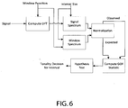
- the apparatus 100 may include means, such as the processor 102, or the like, for computing the DFT spectrum of a multichannel signal. See block 502 of Figure 5 .
- the functions s(n) and w(n) are the signal function and the window function respectively.
- S(k) and W(k) are the DFT of the signal and window functions respectively.
- the window function and the signal in that window are shown in Figure 7 .
- a 48 KhZ sampling rate and a frame size of 20 ms may be used.
- An embodiment may use a 50% overlap with a previous frame for the analysis.
- 20ms of audio data may be read in and then concatenated with 20ms from the preceding frame that was previously processed making a window size of 40ms to which the window function may be applied and the DFT computed. While a 50% overlap is provided as an example here, a different overlap may be used in other embodiments with appropriate changes to the analysis.
- a sine window may be used for analysis, but may alternatively be any other suitable window selected for the analysis.
- the windowed signal may be zero padded to 8192 samples and the DFT may then be computed.
- Example normalized expected and observed distributions are shown in Figure 8 .
- the apparatus 100 may also include means, such as the processor 102, or the like, for computing the goodness of fit statistic.
- the apparatus 100 may also include means, such as the processor 102, or the like, for performing a hypothesis test.
- the hypothesis test requires the significance level, degrees of freedom for chi-square statistic and the actual statistic.
- the Null hypothesis is that a tonal component is found in the interval under consideration. This may happen if the normalized S e and S o closely match, which means the chi-square statistic is small in magnitude. The magnitude actually is used to derive the probability value from a chi-square cumulative distribution table of specific degree determined by M i .
- the Null hypothesis is that a tone is present, at the spectral location around the interval. The Null hypothesis is rejected if the mismatch exceeds the probability value determined by the significance level.
- the hypothesis for drawing an inference about the tonality of the band may be framed in another suitable way as well and is not restricted to the above described example.
- the apparatus 100 may also include means, such as the processor 102, or the like, for determining a tonality decision for a band.
- the band is classified as a tonal. Otherwise, if the Null hypothesis is rejected, the band is categorized as non-tonal.
- the location of the tone is derived as centroid of the spectral region. The tonality decision may then be used in analysis and synthesis as provided in some of the embodiments described with regard to Figure 2 .
- Figure 6 provides a functional block diagram illustrating the operations for tonality determination as performed by an apparatus and described above in relation to Figure 5 .
- FIG 9 shows an example of the output that may be generated by operations as provided in some of the embodiments described with regard to Figure 5 .
- Plot 902 shows the waveform of the signal.
- Plot 904 shows a superimposed spectrum of the frame of the waveform and the tonality decisions and their starting marker points.
- Plot 906 shows the chi-square goodness of fit statistic for each of the DFT bins.
- Figures 2 and 5 illustrate flowcharts of an apparatus, method, and computer program product according to example embodiments of the invention. It will be understood that each block of the flowchart, and combinations of blocks in the flowchart, may be implemented by various means, such as hardware, firmware, processor, circuitry, and/or other devices associated with execution of software including one or more computer program instructions. For example, one or more of the procedures described above may be embodied by computer program instructions. In this regard, the computer program instructions which embody the procedures described above may be stored by a memory 104 of an apparatus employing an embodiment of the present invention and executed by a processor 102 of the apparatus.
- any such computer program instructions may be loaded onto a computer or other programmable apparatus (e.g., hardware) to produce a machine, such that the resulting computer or other programmable apparatus implements the functions specified in the flowchart blocks.
- These computer program instructions may also be stored in a computer-readable memory that may direct a computer or other programmable apparatus to function in a particular manner, such that the instructions stored in the computer-readable memory produce an article of manufacture the execution of which implements the function specified in the flowchart blocks.
- the computer program instructions may also be loaded onto a computer or other programmable apparatus to cause a series of operations to be performed on the computer or other programmable apparatus to produce a computer-implemented process such that the instructions which execute on the computer or other programmable apparatus provide operations for implementing the functions specified in the flowchart blocks.
- blocks of the flowchart support combinations of means for performing the specified functions and combinations of operations for performing the specified functions for performing the specified functions. It will also be understood that one or more blocks of the flowchart, and combinations of blocks in the flowchart, can be implemented by special purpose hardware-based computer systems which perform the specified functions, or combinations of special purpose hardware and computer instructions.
- certain ones of the operations above may be modified or further amplified. Furthermore, in some embodiments, additional optional operations may be included. Modifications, additions, or amplifications to the operations above may be performed in any order and in any combination.
Landscapes
- Engineering & Computer Science (AREA)
- Physics & Mathematics (AREA)
- Acoustics & Sound (AREA)
- Signal Processing (AREA)
- Health & Medical Sciences (AREA)
- Computational Linguistics (AREA)
- Audiology, Speech & Language Pathology (AREA)
- Human Computer Interaction (AREA)
- Multimedia (AREA)
- Mathematical Physics (AREA)
- Spectroscopy & Molecular Physics (AREA)
- Auxiliary Devices For Music (AREA)
- Complex Calculations (AREA)
Claims (13)
- Verfahren, das Folgendes umfasst:Empfangen eines Mehrkanal-Audiosignals;Berechnen des Spektrums für das Mehrkanalsignal;Erzeugen einer Bandstruktur für das Spektrum durch Bestimmen, welche Bänder des Spektrums tonal sind und welche Bänder des Spektrums nicht tonal sind;Ausführen einer räumlichen Analyse nur an den Bändern des Spektrums, die als tonal bestimmt werden, durch Bestimmen einer Verzögerung, die die Korrelation zwischen einem ersten Kanal und einem zweiten Kanal des Mehrkanalsignals maximal macht, durch Transformieren der Verzögerung in einen Winkel in der Azimut-Ebene und durch Verwenden des Winkels, um den räumlichen Ort eines Quellensignals zu bestimmen;Ausführen einer Quellenfilterung an den Bändern des Spektrums, die als tonal bestimmt werden, mit kopfbezogenen Übertragungsfunktionsfiltern; undAusführen einer Synthese an Komponenten der quellengefilterten tonalen Bänder durch Anwenden einer inversen diskreten Fourier-Transformation und durch Anwenden einer Überlappungs- und Additionssynthese.
- Verfahren nach Anspruch 1, wobei das Bestimmen der Tonalität von Bändern in dem Spektrum an wenigstens einem Kanal in dem Mehrkanalsignal ausgeführt wird.
- Verfahren nach einem der Ansprüche 1 oder 2, wobei das Bestimmen der Tonalität von Bändern in dem Spektrum das Bestimmen, ob das Band tonal oder nicht tonal ist, umfasst.
- Verfahren nach einem der Ansprüche 1 bis 3, wobei die Breite der Bänder variabel ist.
- Verfahren nach einem der Ansprüche 1 bis 4, wobei die Tonalitätsbestimmung von Bändern in dem Spektrum auf der statistischen Güte von Passtests beruht.
- Verfahren nach einem der Ansprüche 1 bis 5, wobei die Tonalitätsbestimmung das Vergleichen einer normierten Spektralkomponentenverteilung in einem Band mit einer erweiterten Spektralkomponentenverteilung umfasst.
- Verfahren nach Anspruch 6, wobei die erweiterte Spektralkomponentenverteilung durch eine Sinuskurve erzeugt wird.
- Verfahren nach einem der Ansprüche 6 oder 7, wobei das Vergleichen der Spektralkomponentenverteilungen das Verwenden eines Passgütetests umfasst.
- Verfahren nach einem der Ansprüche 1 bis 8, wobei das Erzeugen einer Bandstruktur für das Spektrum ferner das Berechnen oberer und unterer Grenzen tonaler und nicht tonaler Bänder umfasst.
- Verfahren nach Anspruch 9, wobei das Erzeugen einer Bandstruktur für das Spektrum ferner das Vereinigen mehrerer kontinuierlicher tonaler Bänder zu einem einzigen Band umfasst.
- Computerprogrammprodukt, das auf einem computerlesbaren Medium gespeichert ist und das, wenn es abgearbeitet wird, eine Vorrichtung dazu veranlasst, ein Verfahren nach wenigstens einem der Ansprüche 1 bis 10 auszuführen.
- Vorrichtung, die Folgendes umfasst:Mittel zum Empfangen eines Mehrkanal-Audiosignals;Mittel zum Berechnen des Spektrums für das Mehrkanalsignal;Mittel zum Erzeugen einer Bandstruktur für das Spektrum durch Bestimmen, welche Bänder des Spektrums tonal sind und welche Bänder des Spektrums nicht tonal sind;Mittel zum Ausführen einer räumlichen Analyse nur an den Bändern des Spektrums, die als tonal bestimmt werden, durch Bestimmen einer Verzögerung, die die Korrelation zwischen einem ersten Kanal und einem zweiten Kanal des Mehrkanalsignals maximal macht, durch Transformieren der Verzögerung in einen Winkel in der Azimut-Ebene und durch Verwenden des Winkels, um den räumlichen Ort eines Quellensignals zu bestimmen;Mittel zum Ausführen einer Quellenfilterung an den Bändern des Spektrums, die als tonal bestimmt werden, mit kopfbezogenen Übertragungsfunktionsfiltern; undMittel zum Ausführen einer Synthese an Komponenten der quellengefilterten tonalen Bänder durch Anwenden einer inversen diskreten Fourier-Transformation und durch Anwenden einer Überlappungs- und Additionssynthese.
- Vorrichtung nach Anspruch 12, die ferner Mittel umfasst, um das Verfahren nach wenigstens einem der Ansprüche 2 bis 10 auszuführen.
Applications Claiming Priority (1)
| Application Number | Priority Date | Filing Date | Title |
|---|---|---|---|
| IN4164CH2012 | 2012-10-05 |
Publications (2)
| Publication Number | Publication Date |
|---|---|
| EP2717263A1 EP2717263A1 (de) | 2014-04-09 |
| EP2717263B1 true EP2717263B1 (de) | 2016-11-02 |
Family
ID=49150863
Family Applications (1)
| Application Number | Title | Priority Date | Filing Date |
|---|---|---|---|
| EP13184236.1A Not-in-force EP2717263B1 (de) | 2012-10-05 | 2013-09-13 | Verfahren, Vorrichtung und Computerprogrammprodukt zur kategorischen räumlichen Analyse-Synthese des Spektrums eines Mehrkanal-Audiosignals |
Country Status (2)
| Country | Link |
|---|---|
| US (1) | US9420375B2 (de) |
| EP (1) | EP2717263B1 (de) |
Families Citing this family (6)
| Publication number | Priority date | Publication date | Assignee | Title |
|---|---|---|---|---|
| EP2717263B1 (de) * | 2012-10-05 | 2016-11-02 | Nokia Technologies Oy | Verfahren, Vorrichtung und Computerprogrammprodukt zur kategorischen räumlichen Analyse-Synthese des Spektrums eines Mehrkanal-Audiosignals |
| GB2573537A (en) * | 2018-05-09 | 2019-11-13 | Nokia Technologies Oy | An apparatus, method and computer program for audio signal processing |
| US12413929B2 (en) | 2020-12-17 | 2025-09-09 | Dolby Laboratories Licensing Corporation | Binaural signal post-processing |
| CN113473352B (zh) * | 2021-07-06 | 2023-06-20 | 北京达佳互联信息技术有限公司 | 双声道音频后处理的方法和装置 |
| US12461989B2 (en) * | 2021-11-19 | 2025-11-04 | Minitab, Llc | Correcting low-resolution measurements |
| US20230161839A1 (en) * | 2021-11-19 | 2023-05-25 | Minitab, Llc | Correcting low-resolution measurements |
Family Cites Families (26)
| Publication number | Priority date | Publication date | Assignee | Title |
|---|---|---|---|---|
| US5040217A (en) * | 1989-10-18 | 1991-08-13 | At&T Bell Laboratories | Perceptual coding of audio signals |
| JP3153933B2 (ja) * | 1992-06-16 | 2001-04-09 | ソニー株式会社 | データ符号化装置及び方法並びにデータ復号化装置及び方法 |
| TW295747B (de) * | 1994-06-13 | 1997-01-11 | Sony Co Ltd | |
| JP3250376B2 (ja) * | 1994-06-13 | 2002-01-28 | ソニー株式会社 | 情報符号化方法及び装置並びに情報復号化方法及び装置 |
| JP3277692B2 (ja) * | 1994-06-13 | 2002-04-22 | ソニー株式会社 | 情報符号化方法、情報復号化方法及び情報記録媒体 |
| US6064955A (en) * | 1998-04-13 | 2000-05-16 | Motorola | Low complexity MBE synthesizer for very low bit rate voice messaging |
| DE60042335D1 (de) | 1999-12-24 | 2009-07-16 | Koninkl Philips Electronics Nv | Mehrkanal-audiosignalverarbeitungsgerät |
| US20030123574A1 (en) | 2001-12-31 | 2003-07-03 | Simeon Richard Corpuz | System and method for robust tone detection |
| US7020603B2 (en) * | 2002-02-07 | 2006-03-28 | Intel Corporation | Audio coding and transcoding using perceptual distortion templates |
| US7447631B2 (en) * | 2002-06-17 | 2008-11-04 | Dolby Laboratories Licensing Corporation | Audio coding system using spectral hole filling |
| US7050965B2 (en) * | 2002-06-03 | 2006-05-23 | Intel Corporation | Perceptual normalization of digital audio signals |
| US20080056517A1 (en) | 2002-10-18 | 2008-03-06 | The Regents Of The University Of California | Dynamic binaural sound capture and reproduction in focued or frontal applications |
| US7117108B2 (en) * | 2003-05-28 | 2006-10-03 | Paul Ernest Rapp | System and method for categorical analysis of time dependent dynamic processes |
| US7386962B2 (en) | 2004-03-05 | 2008-06-17 | L & T Riser Llc | Batten riser assembly |
| WO2006070560A1 (ja) * | 2004-12-28 | 2006-07-06 | Pioneer Corporation | 雑音抑圧装置、雑音抑圧方法、雑音抑圧プログラムおよびコンピュータに読み取り可能な記録媒体 |
| WO2007028250A2 (en) * | 2005-09-09 | 2007-03-15 | Mcmaster University | Method and device for binaural signal enhancement |
| WO2007052088A1 (en) | 2005-11-04 | 2007-05-10 | Nokia Corporation | Audio compression |
| US8219392B2 (en) * | 2005-12-05 | 2012-07-10 | Qualcomm Incorporated | Systems, methods, and apparatus for detection of tonal components employing a coding operation with monotone function |
| CN101416237B (zh) * | 2006-05-01 | 2012-05-30 | 日本电信电话株式会社 | 基于源和室内声学的概率模型的语音去混响方法和设备 |
| US8619998B2 (en) | 2006-08-07 | 2013-12-31 | Creative Technology Ltd | Spatial audio enhancement processing method and apparatus |
| US7876904B2 (en) | 2006-07-08 | 2011-01-25 | Nokia Corporation | Dynamic decoding of binaural audio signals |
| WO2009048239A2 (en) | 2007-10-12 | 2009-04-16 | Electronics And Telecommunications Research Institute | Encoding and decoding method using variable subband analysis and apparatus thereof |
| JP5366104B2 (ja) | 2008-06-26 | 2013-12-11 | オランジュ | マルチチャネル・オーディオ信号の空間合成 |
| KR101395252B1 (ko) * | 2008-07-11 | 2014-05-15 | 프라운호퍼 게젤샤프트 쭈르 푀르데룽 데어 안겐반텐 포르슝 에. 베. | 스펙트럼 포락선의 수를 산출하기 위한 장치 및 그 방법 |
| GB2467534B (en) * | 2009-02-04 | 2014-12-24 | Richard Furse | Sound system |
| EP2717263B1 (de) * | 2012-10-05 | 2016-11-02 | Nokia Technologies Oy | Verfahren, Vorrichtung und Computerprogrammprodukt zur kategorischen räumlichen Analyse-Synthese des Spektrums eines Mehrkanal-Audiosignals |
-
2013
- 2013-09-13 EP EP13184236.1A patent/EP2717263B1/de not_active Not-in-force
- 2013-09-27 US US14/039,357 patent/US9420375B2/en not_active Expired - Fee Related
Also Published As
| Publication number | Publication date |
|---|---|
| EP2717263A1 (de) | 2014-04-09 |
| US9420375B2 (en) | 2016-08-16 |
| US20140177845A1 (en) | 2014-06-26 |
Similar Documents
| Publication | Publication Date | Title |
|---|---|---|
| Chi et al. | Multiresolution spectrotemporal analysis of complex sounds | |
| US9420375B2 (en) | Method, apparatus, and computer program product for categorical spatial analysis-synthesis on spectrum of multichannel audio signals | |
| Van Kuyk et al. | An evaluation of intrusive instrumental intelligibility metrics | |
| US8767978B2 (en) | System and method for processing sound signals implementing a spectral motion transform | |
| Relaño-Iborra et al. | Predicting speech intelligibility based on a correlation metric in the envelope power spectrum domain | |
| CN112786057B (zh) | 一种声纹识别方法、装置、电子设备及存储介质 | |
| US20130246062A1 (en) | System and Method for Robust Estimation and Tracking the Fundamental Frequency of Pseudo Periodic Signals in the Presence of Noise | |
| CN111048071B (zh) | 语音数据处理方法、装置、计算机设备和存储介质 | |
| WO2021000498A1 (zh) | 复合语音识别方法、装置、设备及计算机可读存储介质 | |
| JP6334895B2 (ja) | 信号処理装置及びその制御方法、プログラム | |
| EP2209117A1 (de) | Verfahren zum Bestimmen von unbeeinflussten Signalamplitudenschätzungen nach einer Cepstralvarianzänderung | |
| CN114830686A (zh) | 声源的改进定位 | |
| Balaji et al. | Radial basis function neural network based speech enhancement system using SLANTLET transform through hybrid vector wiener filter | |
| CN104282303B (zh) | 利用声纹识别进行语音辨识的方法及其电子装置 | |
| Unoki et al. | An improved method based on the MTF concept for restoring the power envelope from a reverberant signal | |
| CN115565523B (zh) | 一种基于神经网络的端到端信道质量评估方法及系统 | |
| Nakajima et al. | Monaural source enhancement maximizing source-to-distortion ratio via automatic differentiation | |
| Yarra et al. | A mode-shape classification technique for robust speech rate estimation and syllable nuclei detection | |
| Ristić et al. | Detection of early reflections using multifractals | |
| CN106340310B (zh) | 语音检测方法及装置 | |
| TWI585756B (zh) | 口吃偵測方法與裝置、電腦程式產品 | |
| Mehta et al. | Statistical properties of linear prediction analysis underlying the challenge of formant bandwidth estimation | |
| Płonkowski | Using bands of frequencies for vowel recognition for Polish language | |
| CN117528305A (zh) | 拾音控制方法、装置及设备 | |
| CN110580917B (zh) | 一种语音数据质量检测方法、装置、服务器及存储介质 |
Legal Events
| Date | Code | Title | Description |
|---|---|---|---|
| PUAI | Public reference made under article 153(3) epc to a published international application that has entered the european phase |
Free format text: ORIGINAL CODE: 0009012 |
|
| AK | Designated contracting states |
Kind code of ref document: A1 Designated state(s): AL AT BE BG CH CY CZ DE DK EE ES FI FR GB GR HR HU IE IS IT LI LT LU LV MC MK MT NL NO PL PT RO RS SE SI SK SM TR |
|
| AX | Request for extension of the european patent |
Extension state: BA ME |
|
| RAP1 | Party data changed (applicant data changed or rights of an application transferred) |
Owner name: NOKIA CORPORATION |
|
| 17P | Request for examination filed |
Effective date: 20141006 |
|
| RBV | Designated contracting states (corrected) |
Designated state(s): AL AT BE BG CH CY CZ DE DK EE ES FI FR GB GR HR HU IE IS IT LI LT LU LV MC MK MT NL NO PL PT RO RS SE SI SK SM TR |
|
| RAP1 | Party data changed (applicant data changed or rights of an application transferred) |
Owner name: NOKIA TECHNOLOGIES OY |
|
| REG | Reference to a national code |
Ref country code: DE Ref legal event code: R079 Ref document number: 602013013417 Country of ref document: DE Free format text: PREVIOUS MAIN CLASS: G10L0019008000 Ipc: H04S0007000000 |
|
| RIC1 | Information provided on ipc code assigned before grant |
Ipc: G10L 19/008 20130101ALI20160422BHEP Ipc: G10L 19/20 20130101ALI20160422BHEP Ipc: G10L 19/02 20130101ALI20160422BHEP Ipc: H04S 7/00 20060101AFI20160422BHEP |
|
| GRAP | Despatch of communication of intention to grant a patent |
Free format text: ORIGINAL CODE: EPIDOSNIGR1 |
|
| INTG | Intention to grant announced |
Effective date: 20160603 |
|
| GRAS | Grant fee paid |
Free format text: ORIGINAL CODE: EPIDOSNIGR3 |
|
| GRAA | (expected) grant |
Free format text: ORIGINAL CODE: 0009210 |
|
| AK | Designated contracting states |
Kind code of ref document: B1 Designated state(s): AL AT BE BG CH CY CZ DE DK EE ES FI FR GB GR HR HU IE IS IT LI LT LU LV MC MK MT NL NO PL PT RO RS SE SI SK SM TR |
|
| REG | Reference to a national code |
Ref country code: GB Ref legal event code: FG4D |
|
| REG | Reference to a national code |
Ref country code: AT Ref legal event code: REF Ref document number: 842903 Country of ref document: AT Kind code of ref document: T Effective date: 20161115 Ref country code: CH Ref legal event code: EP |
|
| REG | Reference to a national code |
Ref country code: IE Ref legal event code: FG4D |
|
| REG | Reference to a national code |
Ref country code: DE Ref legal event code: R096 Ref document number: 602013013417 Country of ref document: DE |
|
| REG | Reference to a national code |
Ref country code: NL Ref legal event code: FP |
|
| PG25 | Lapsed in a contracting state [announced via postgrant information from national office to epo] |
Ref country code: LV Free format text: LAPSE BECAUSE OF FAILURE TO SUBMIT A TRANSLATION OF THE DESCRIPTION OR TO PAY THE FEE WITHIN THE PRESCRIBED TIME-LIMIT Effective date: 20161102 |
|
| REG | Reference to a national code |
Ref country code: LT Ref legal event code: MG4D |
|
| REG | Reference to a national code |
Ref country code: AT Ref legal event code: MK05 Ref document number: 842903 Country of ref document: AT Kind code of ref document: T Effective date: 20161102 |
|
| PG25 | Lapsed in a contracting state [announced via postgrant information from national office to epo] |
Ref country code: LT Free format text: LAPSE BECAUSE OF FAILURE TO SUBMIT A TRANSLATION OF THE DESCRIPTION OR TO PAY THE FEE WITHIN THE PRESCRIBED TIME-LIMIT Effective date: 20161102 Ref country code: NO Free format text: LAPSE BECAUSE OF FAILURE TO SUBMIT A TRANSLATION OF THE DESCRIPTION OR TO PAY THE FEE WITHIN THE PRESCRIBED TIME-LIMIT Effective date: 20170202 Ref country code: SE Free format text: LAPSE BECAUSE OF FAILURE TO SUBMIT A TRANSLATION OF THE DESCRIPTION OR TO PAY THE FEE WITHIN THE PRESCRIBED TIME-LIMIT Effective date: 20161102 Ref country code: GR Free format text: LAPSE BECAUSE OF FAILURE TO SUBMIT A TRANSLATION OF THE DESCRIPTION OR TO PAY THE FEE WITHIN THE PRESCRIBED TIME-LIMIT Effective date: 20170203 |
|
| PG25 | Lapsed in a contracting state [announced via postgrant information from national office to epo] |
Ref country code: HR Free format text: LAPSE BECAUSE OF FAILURE TO SUBMIT A TRANSLATION OF THE DESCRIPTION OR TO PAY THE FEE WITHIN THE PRESCRIBED TIME-LIMIT Effective date: 20161102 Ref country code: RS Free format text: LAPSE BECAUSE OF FAILURE TO SUBMIT A TRANSLATION OF THE DESCRIPTION OR TO PAY THE FEE WITHIN THE PRESCRIBED TIME-LIMIT Effective date: 20161102 Ref country code: FI Free format text: LAPSE BECAUSE OF FAILURE TO SUBMIT A TRANSLATION OF THE DESCRIPTION OR TO PAY THE FEE WITHIN THE PRESCRIBED TIME-LIMIT Effective date: 20161102 Ref country code: PT Free format text: LAPSE BECAUSE OF FAILURE TO SUBMIT A TRANSLATION OF THE DESCRIPTION OR TO PAY THE FEE WITHIN THE PRESCRIBED TIME-LIMIT Effective date: 20170302 Ref country code: ES Free format text: LAPSE BECAUSE OF FAILURE TO SUBMIT A TRANSLATION OF THE DESCRIPTION OR TO PAY THE FEE WITHIN THE PRESCRIBED TIME-LIMIT Effective date: 20161102 Ref country code: AT Free format text: LAPSE BECAUSE OF FAILURE TO SUBMIT A TRANSLATION OF THE DESCRIPTION OR TO PAY THE FEE WITHIN THE PRESCRIBED TIME-LIMIT Effective date: 20161102 Ref country code: PL Free format text: LAPSE BECAUSE OF FAILURE TO SUBMIT A TRANSLATION OF THE DESCRIPTION OR TO PAY THE FEE WITHIN THE PRESCRIBED TIME-LIMIT Effective date: 20161102 Ref country code: IS Free format text: LAPSE BECAUSE OF FAILURE TO SUBMIT A TRANSLATION OF THE DESCRIPTION OR TO PAY THE FEE WITHIN THE PRESCRIBED TIME-LIMIT Effective date: 20170302 |
|
| PG25 | Lapsed in a contracting state [announced via postgrant information from national office to epo] |
Ref country code: DK Free format text: LAPSE BECAUSE OF FAILURE TO SUBMIT A TRANSLATION OF THE DESCRIPTION OR TO PAY THE FEE WITHIN THE PRESCRIBED TIME-LIMIT Effective date: 20161102 Ref country code: SK Free format text: LAPSE BECAUSE OF FAILURE TO SUBMIT A TRANSLATION OF THE DESCRIPTION OR TO PAY THE FEE WITHIN THE PRESCRIBED TIME-LIMIT Effective date: 20161102 Ref country code: CZ Free format text: LAPSE BECAUSE OF FAILURE TO SUBMIT A TRANSLATION OF THE DESCRIPTION OR TO PAY THE FEE WITHIN THE PRESCRIBED TIME-LIMIT Effective date: 20161102 Ref country code: RO Free format text: LAPSE BECAUSE OF FAILURE TO SUBMIT A TRANSLATION OF THE DESCRIPTION OR TO PAY THE FEE WITHIN THE PRESCRIBED TIME-LIMIT Effective date: 20161102 Ref country code: EE Free format text: LAPSE BECAUSE OF FAILURE TO SUBMIT A TRANSLATION OF THE DESCRIPTION OR TO PAY THE FEE WITHIN THE PRESCRIBED TIME-LIMIT Effective date: 20161102 |
|
| REG | Reference to a national code |
Ref country code: DE Ref legal event code: R097 Ref document number: 602013013417 Country of ref document: DE |
|
| PG25 | Lapsed in a contracting state [announced via postgrant information from national office to epo] |
Ref country code: BE Free format text: LAPSE BECAUSE OF FAILURE TO SUBMIT A TRANSLATION OF THE DESCRIPTION OR TO PAY THE FEE WITHIN THE PRESCRIBED TIME-LIMIT Effective date: 20161102 Ref country code: SM Free format text: LAPSE BECAUSE OF FAILURE TO SUBMIT A TRANSLATION OF THE DESCRIPTION OR TO PAY THE FEE WITHIN THE PRESCRIBED TIME-LIMIT Effective date: 20161102 Ref country code: BG Free format text: LAPSE BECAUSE OF FAILURE TO SUBMIT A TRANSLATION OF THE DESCRIPTION OR TO PAY THE FEE WITHIN THE PRESCRIBED TIME-LIMIT Effective date: 20170202 Ref country code: IT Free format text: LAPSE BECAUSE OF FAILURE TO SUBMIT A TRANSLATION OF THE DESCRIPTION OR TO PAY THE FEE WITHIN THE PRESCRIBED TIME-LIMIT Effective date: 20161102 |
|
| PLBE | No opposition filed within time limit |
Free format text: ORIGINAL CODE: 0009261 |
|
| STAA | Information on the status of an ep patent application or granted ep patent |
Free format text: STATUS: NO OPPOSITION FILED WITHIN TIME LIMIT |
|
| 26N | No opposition filed |
Effective date: 20170803 |
|
| PG25 | Lapsed in a contracting state [announced via postgrant information from national office to epo] |
Ref country code: SI Free format text: LAPSE BECAUSE OF FAILURE TO SUBMIT A TRANSLATION OF THE DESCRIPTION OR TO PAY THE FEE WITHIN THE PRESCRIBED TIME-LIMIT Effective date: 20161102 |
|
| REG | Reference to a national code |
Ref country code: CH Ref legal event code: PL |
|
| GBPC | Gb: european patent ceased through non-payment of renewal fee |
Effective date: 20170913 |
|
| PG25 | Lapsed in a contracting state [announced via postgrant information from national office to epo] |
Ref country code: MC Free format text: LAPSE BECAUSE OF FAILURE TO SUBMIT A TRANSLATION OF THE DESCRIPTION OR TO PAY THE FEE WITHIN THE PRESCRIBED TIME-LIMIT Effective date: 20161102 |
|
| REG | Reference to a national code |
Ref country code: IE Ref legal event code: MM4A |
|
| PG25 | Lapsed in a contracting state [announced via postgrant information from national office to epo] |
Ref country code: LU Free format text: LAPSE BECAUSE OF NON-PAYMENT OF DUE FEES Effective date: 20170913 |
|
| REG | Reference to a national code |
Ref country code: FR Ref legal event code: ST Effective date: 20180531 |
|
| PG25 | Lapsed in a contracting state [announced via postgrant information from national office to epo] |
Ref country code: GB Free format text: LAPSE BECAUSE OF NON-PAYMENT OF DUE FEES Effective date: 20170913 Ref country code: IE Free format text: LAPSE BECAUSE OF NON-PAYMENT OF DUE FEES Effective date: 20170913 Ref country code: CH Free format text: LAPSE BECAUSE OF NON-PAYMENT OF DUE FEES Effective date: 20170930 Ref country code: LI Free format text: LAPSE BECAUSE OF NON-PAYMENT OF DUE FEES Effective date: 20170930 |
|
| PG25 | Lapsed in a contracting state [announced via postgrant information from national office to epo] |
Ref country code: FR Free format text: LAPSE BECAUSE OF NON-PAYMENT OF DUE FEES Effective date: 20171002 |
|
| PG25 | Lapsed in a contracting state [announced via postgrant information from national office to epo] |
Ref country code: MT Free format text: LAPSE BECAUSE OF NON-PAYMENT OF DUE FEES Effective date: 20170913 |
|
| PGFP | Annual fee paid to national office [announced via postgrant information from national office to epo] |
Ref country code: NL Payment date: 20180912 Year of fee payment: 6 |
|
| PG25 | Lapsed in a contracting state [announced via postgrant information from national office to epo] |
Ref country code: HU Free format text: LAPSE BECAUSE OF FAILURE TO SUBMIT A TRANSLATION OF THE DESCRIPTION OR TO PAY THE FEE WITHIN THE PRESCRIBED TIME-LIMIT; INVALID AB INITIO Effective date: 20130913 |
|
| PG25 | Lapsed in a contracting state [announced via postgrant information from national office to epo] |
Ref country code: CY Free format text: LAPSE BECAUSE OF NON-PAYMENT OF DUE FEES Effective date: 20161102 |
|
| PGFP | Annual fee paid to national office [announced via postgrant information from national office to epo] |
Ref country code: DE Payment date: 20190903 Year of fee payment: 7 |
|
| PG25 | Lapsed in a contracting state [announced via postgrant information from national office to epo] |
Ref country code: MK Free format text: LAPSE BECAUSE OF FAILURE TO SUBMIT A TRANSLATION OF THE DESCRIPTION OR TO PAY THE FEE WITHIN THE PRESCRIBED TIME-LIMIT Effective date: 20161102 |
|
| PG25 | Lapsed in a contracting state [announced via postgrant information from national office to epo] |
Ref country code: TR Free format text: LAPSE BECAUSE OF FAILURE TO SUBMIT A TRANSLATION OF THE DESCRIPTION OR TO PAY THE FEE WITHIN THE PRESCRIBED TIME-LIMIT Effective date: 20161102 |
|
| REG | Reference to a national code |
Ref country code: NL Ref legal event code: MM Effective date: 20191001 |
|
| PG25 | Lapsed in a contracting state [announced via postgrant information from national office to epo] |
Ref country code: AL Free format text: LAPSE BECAUSE OF FAILURE TO SUBMIT A TRANSLATION OF THE DESCRIPTION OR TO PAY THE FEE WITHIN THE PRESCRIBED TIME-LIMIT Effective date: 20161102 Ref country code: NL Free format text: LAPSE BECAUSE OF NON-PAYMENT OF DUE FEES Effective date: 20191001 |
|
| REG | Reference to a national code |
Ref country code: DE Ref legal event code: R119 Ref document number: 602013013417 Country of ref document: DE |
|
| PG25 | Lapsed in a contracting state [announced via postgrant information from national office to epo] |
Ref country code: DE Free format text: LAPSE BECAUSE OF NON-PAYMENT OF DUE FEES Effective date: 20210401 |