EP2717410A1 - Dispositif de commande d'alimentation et procédé de commande d'alimentation - Google Patents
Dispositif de commande d'alimentation et procédé de commande d'alimentation Download PDFInfo
- Publication number
- EP2717410A1 EP2717410A1 EP12789252.9A EP12789252A EP2717410A1 EP 2717410 A1 EP2717410 A1 EP 2717410A1 EP 12789252 A EP12789252 A EP 12789252A EP 2717410 A1 EP2717410 A1 EP 2717410A1
- Authority
- EP
- European Patent Office
- Prior art keywords
- power
- stand
- supplied
- demanded
- load equipment
- Prior art date
- Legal status (The legal status is an assumption and is not a legal conclusion. Google has not performed a legal analysis and makes no representation as to the accuracy of the status listed.)
- Granted
Links
Images



Classifications
-
- H—ELECTRICITY
- H02—GENERATION; CONVERSION OR DISTRIBUTION OF ELECTRIC POWER
- H02J—ELECTRIC POWER NETWORKS; CIRCUIT ARRANGEMENTS OR SYSTEMS FOR SUPPLYING OR DISTRIBUTING ELECTRIC POWER; SYSTEMS FOR STORING ELECTRIC ENERGY
- H02J9/00—Circuit arrangements for emergency or stand-by power supply, e.g. for emergency lighting
- H02J9/04—Circuit arrangements for emergency or stand-by power supply, e.g. for emergency lighting in which the distribution system is disconnected from the normal source and connected to a standby source
- H02J9/06—Circuit arrangements for emergency or stand-by power supply, e.g. for emergency lighting in which the distribution system is disconnected from the normal source and connected to a standby source with automatic change-over, e.g. UPS systems
-
- H—ELECTRICITY
- H02—GENERATION; CONVERSION OR DISTRIBUTION OF ELECTRIC POWER
- H02J—ELECTRIC POWER NETWORKS; CIRCUIT ARRANGEMENTS OR SYSTEMS FOR SUPPLYING OR DISTRIBUTING ELECTRIC POWER; SYSTEMS FOR STORING ELECTRIC ENERGY
- H02J3/00—Circuit arrangements for AC mains or AC distribution networks
- H02J3/38—Arrangements for feeding a single network from two or more generators or sources in parallel; Arrangements for feeding already energised networks from additional generators or sources in parallel
- H02J3/46—Controlling the sharing of generated power between the generators, sources or networks
- H02J3/466—Scheduling or selectively controlling the operation of the generators or sources, e.g. connecting or disconnecting generators to meet a demand
-
- H—ELECTRICITY
- H02—GENERATION; CONVERSION OR DISTRIBUTION OF ELECTRIC POWER
- H02J—ELECTRIC POWER NETWORKS; CIRCUIT ARRANGEMENTS OR SYSTEMS FOR SUPPLYING OR DISTRIBUTING ELECTRIC POWER; SYSTEMS FOR STORING ELECTRIC ENERGY
- H02J2101/00—Supply or distribution of decentralised, dispersed or local electric power generation
- H02J2101/20—Dispersed power generation using renewable energy sources
- H02J2101/22—Solar energy
- H02J2101/24—Photovoltaics
-
- H—ELECTRICITY
- H02—GENERATION; CONVERSION OR DISTRIBUTION OF ELECTRIC POWER
- H02J—ELECTRIC POWER NETWORKS; CIRCUIT ARRANGEMENTS OR SYSTEMS FOR SUPPLYING OR DISTRIBUTING ELECTRIC POWER; SYSTEMS FOR STORING ELECTRIC ENERGY
- H02J3/00—Circuit arrangements for AC mains or AC distribution networks
- H02J3/38—Arrangements for feeding a single network from two or more generators or sources in parallel; Arrangements for feeding already energised networks from additional generators or sources in parallel
- H02J3/381—Dispersed generators
-
- H—ELECTRICITY
- H02—GENERATION; CONVERSION OR DISTRIBUTION OF ELECTRIC POWER
- H02J—ELECTRIC POWER NETWORKS; CIRCUIT ARRANGEMENTS OR SYSTEMS FOR SUPPLYING OR DISTRIBUTING ELECTRIC POWER; SYSTEMS FOR STORING ELECTRIC ENERGY
- H02J3/00—Circuit arrangements for AC mains or AC distribution networks
- H02J3/38—Arrangements for feeding a single network from two or more generators or sources in parallel; Arrangements for feeding already energised networks from additional generators or sources in parallel
- H02J3/388—Arrangements for the handling of islanding, e.g. for disconnection or for avoiding the disconnection of power
-
- Y—GENERAL TAGGING OF NEW TECHNOLOGICAL DEVELOPMENTS; GENERAL TAGGING OF CROSS-SECTIONAL TECHNOLOGIES SPANNING OVER SEVERAL SECTIONS OF THE IPC; TECHNICAL SUBJECTS COVERED BY FORMER USPC CROSS-REFERENCE ART COLLECTIONS [XRACs] AND DIGESTS
- Y02—TECHNOLOGIES OR APPLICATIONS FOR MITIGATION OR ADAPTATION AGAINST CLIMATE CHANGE
- Y02B—CLIMATE CHANGE MITIGATION TECHNOLOGIES RELATED TO BUILDINGS, e.g. HOUSING, HOUSE APPLIANCES OR RELATED END-USER APPLICATIONS
- Y02B10/00—Integration of renewable energy sources in buildings
- Y02B10/70—Hybrid systems, e.g. uninterruptible or back-up power supplies integrating renewable energies
-
- Y—GENERAL TAGGING OF NEW TECHNOLOGICAL DEVELOPMENTS; GENERAL TAGGING OF CROSS-SECTIONAL TECHNOLOGIES SPANNING OVER SEVERAL SECTIONS OF THE IPC; TECHNICAL SUBJECTS COVERED BY FORMER USPC CROSS-REFERENCE ART COLLECTIONS [XRACs] AND DIGESTS
- Y02—TECHNOLOGIES OR APPLICATIONS FOR MITIGATION OR ADAPTATION AGAINST CLIMATE CHANGE
- Y02E—REDUCTION OF GREENHOUSE GAS [GHG] EMISSIONS, RELATED TO ENERGY GENERATION, TRANSMISSION OR DISTRIBUTION
- Y02E10/00—Energy generation through renewable energy sources
- Y02E10/50—Photovoltaic [PV] energy
- Y02E10/56—Power conversion systems, e.g. maximum power point trackers
Definitions
- the present invention relates to a power control apparatus and a power control method.
- the power control apparatus is provided at a consumer site having a distributed power supply and a load equipment, and controls a stand-alone operation in which power supplied from the distributed power is converted into AC power and the converted AC power is supplied to the load equipment.
- power control apparatuses for converting power supplied from distributed power supply, e.g., photovoltaic cells, wind power generators, etc., into AC power is becoming pervasive at power consumer sites, e.g., ordinary homes.
- Such power control apparatuses can also execute a stand-alone operation for supplying power supplied from distributed power supply to load equipments at consumer sites, for example, when the power system breaks down (for example, refer to Patent Literature 1).
- the power output from distributed power supply depends on the weather. Accordingly, the power supplied to a load equipment from distributed power supply (hereinafter referred to as supplied power) at the time of a stand-alone operation may not satisfy power required for operating the load equipment (hereinafter referred to as demanded power). In such a case, a sufficient quantity of power cannot be supplied to the load equipment, and therefore a correct operation of the load equipment is not ensured.
- such a power control apparatus executes an output determination process for determining whether or not a supplied power from distributed power supply satisfies a demanded power required for operating the load equipment.
- a first feature is summarized as a power control apparatus, provided at a consumer site having a distributed power supply capable of supplying power and a load equipment, controlling a stand-alone operation in which power supplied from the distributed power supply is converted into AC power and the converted AC power is supplied to the load equipment, the power control apparatus comprising: a determination processing unit that determines whether or not a supplied power from the distributed power supply satisfies a demanded power required for operating the load equipment, when it operates in the stand-alone operation; and a supply control unit that suspends the stand-alone operation if it is determined that the supplied power does not satisfy the demanded power, wherein the determination processing unit re-executes the stand-alone operation after suspending the stand-alone operation, and determines whether or not the supplied power satisfies the demanded power, and stops the re-executing of the stand-alone operation if it is determined continuously for a predetermined number of times that the supplied power does not satisfy the demanded power, or if a predetermined period e
- the determination processing unit executes the re-executing process and the determining process at predetermined intervals, after suspending the stand-alone operation.
- the determination processing unit starts supplying an output from the distributed power supply to the load equipment after the re-executing process, and executes the determining process after starting to supply the power.
- the determination processing unit starts power supply from the distributed power supply to the load equipment, after a first time period elapses from the re-executing process.
- the determination processing unit executes the determining process after a second time period elapses from a start of the power supply from the distributed power supply to the load equipment is started.
- the determination processing unit does not stop the re-executing process if the load equipment is not a specific device, even if it is determined continuously for the predetermined number of times that the supplied power does not satisfy the demanded power, or even if the predetermined period elapses after determining that the supplied power does not satisfy the demanded power without determining that the supplied power satisfies the demanded power.
- the power control apparatus comprises: an interface that communicates with a power management device that manages power of the load equipment, and that obtains type information on whether or not the load equipment is the specific device.
- the specific device is a space heater or a voice output device.
- the power control apparatus comprises: an interface that communicates with a power management device that manages power of the load equipment.
- the determination processing unit instructs the power management device to stop the operation via the interface when the load equipment corresponding to a specific device exists, if it is determined continuously for a predetermined number of times that the supplied power does not satisfy the demanded power, or if a predetermined period elapses after determining that the supplied power does not satisfy the demanded power without determining that the supplied power satisfies the demanded power.
- the specific device is a space heater or a voice output device.
- a second feature is summarized as a power control method in a power control apparatus provided at a consumer site having a distributed power supply capable of supplying power and a load equipment, the power control apparatus that controls a stand-alone operation in which power supplied from the distributed power supply is converted into AC power and the converted AC power is supplied to the load equipment, the power control method comprising: a step of determining whether or not a supplied power from the distributed power supply satisfies a demanded power required for operating a load equipment, at the time of the stand-alone operation; a step of suspending the stand-alone operation if it is determined that the supplied power not satisfying the demanded power; a step of re-executing the stand-alone operation after suspending the stand-alone operation, and determining whether or not the supplied power satisfies the demanded power; and a step of stopping the re-executing of the stand-alone operation if it is determined continuously for a predetermined number of times that the supplied power does not satisfy the demanded power, or if a
- Fig. 1 is a schematic structure diagram of the power control system 1 according to the present embodiment.
- a power control system 1 is provided at consumer sites, e.g., ordinary homes, and can execute power control of load equipments at the consumer site.
- a solid line indicates a power line
- a dashed line indicates a control signal line.
- the power control system 1 includes a photovoltaic cell 20 for generating direct current (DC) power, a load equipment 30 connected to stand-alone system line 12, and a power conditioner 100.
- the power control system 1 also includes a load equipment etc., connected to a cabinet panel or power system line 11 in addition to the above-mentioned components, descriptions thereof are omitted in the present embodiment.
- the power system line 11 is a distribution line connected between a power system 10 and a power system side output unit 131 of the power conditioner 100 (described later).
- the stand-alone system line 12 is a distribution line connected to a stand-alone system side output unit 132 of the power conditioner 100 (described later).
- a photovoltaic cell 20 can receive sunlight, and generate DC power in accordance with the received sunlight.
- the photovoltaic cell 20 outputs the generated DC power to the power conditioner 100.
- the photovoltaic cell 20 configures distributed power supply capable of supplying power into a consumer site.
- the power control system 1 may further include a storage battery as distributed power supply.
- the load equipments 30 envisioned include home electronics provided at the consumer site, e.g., electric heaters, televisions, lighting devices, and air-conditioners.
- the load equipment 30 is connected to the stand-alone system line 12.
- the cabinet panel etc. can switch so that the load equipment 30 may connect to any one of the power system line 11 and the stand-alone system line 12.
- the cabinet panel etc. may connect the load equipment 30 to the stand-alone system line 12 only at the time of the stand-alone operation.
- the power conditioner 100 is connected to the photovoltaic cell 20, the power system line 11, and the stand-alone system line 12. Moreover, the power conditioner 100 can switch between an interconnection operation for outputting power supplied from the photovoltaic cell 20 to the power system line 11, and a stand-alone operation for outputting the power supplied from the photovoltaic cell 20 to the stand-alone system line 12.
- the power conditioner 100 converts DC power generated by the photovoltaic cell 20 into AC power, and outputs the AC power to the power system line 11.
- the AC power output to the power system line 11 is suitably used in the load equipment, or becomes power reverse-flowed to the power system 10.
- the power conditioner 100 converts DC power generated by the photovoltaic cell 20 into AC power, and outputs the AC power to the stand-alone system line 12.
- the AC power output to the stand-alone system line 12 is suitably used in the load equipment 30. That is, the AC power output to the stand-alone system line 12 is consumed by the load equipment 30 provided at the consumer site. Note that details of a configuration of the power conditioner 100 will be described later. In the present embodiment, the power conditioner 100 configures a power control apparatus.
- the power conditioner 100 includes a DC/DC converter 110, a DC/AC converter 111, an interconnection relay 121, a stand-alone relay 122, a power system side output unit 131, a stand-alone system side output unit 132, a measuring unit 140, an external I/F 150, and a control unit 170.
- the power conditioner 100 includes a display unit that displays information including an operation condition for users, and an input unit that accepts instructions from the users, etc., but descriptions thereof are omitted herein.
- the DC/DC converter 110 inputs DC power output from the photovoltaic cell 20, and executes DC/DC conversion (boosting conversion) of the DC power and outputs the converted power to the DC/AC converter 111.
- the DC/AC converter 111 converts the DC power output from the DC/DC converter 110 to AC power, and outputs the AC power to the interconnection relay 121 and the stand-alone relay 122. At this time, the DC/AC converter 111 outputs the AC power while executing a constant voltage output control for stabilizing the AC power at predetermined voltage (for example, AC100V).
- predetermined voltage for example, AC100V
- the interconnection relay 121 is provided between the DC/AC converter 111 and the power system side output unit 131.
- the interconnection relay 121 connects or disconnects between the DC/AC converter 111 and the power system side output unit 131 by switching a closing operation or an opening operation.
- the interconnection relay 121 connects (interconnects) between the DC/AC converter 111 and the power system side output unit 131, and outputs the power to the power system side output unit 131.
- the interconnection relay 121 disconnects (parallels off) between the DC/AC converter 111 and the power system side output unit 131, and stops the output of power to the power system side output unit 131. Note that the interconnection relay 121 executes connection or disconnection in response to instructions from the control unit 170.
- the stand-alone relay 122 is provided between the DC/AC converter 111 and the stand-alone system side output unit 132.
- the stand-alone relay 122 connects or disconnects between the DC/AC converter 111 and the stand-alone system side output unit 132 by switching a closing operation or an opening operation.
- the stand-alone relay 122 disconnects between the DC/AC converter 111 and the stand-alone system side output unit 132, and stops the output of power to the stand-alone system side output unit 132.
- the stand-alone relay 122 connects between the DC/AC converter 111 and the stand-alone system side output unit 132, and outputs power to the stand-alone system side output unit 132.
- the stand-alone relay 122 executes connection or disconnection in response to instructions from the control unit 170.
- the power system side output unit 131 outputs the power output from the DC/AC converter 111 to the power system line 11 via the interconnection relay 121. Note that the power system side output unit 131 outputs power to the power system line 11 only at the time of the interconnection operation.
- the stand-alone system side output unit 132 outputs the power output from the DC/AC converter 111 to the stand-alone system line 12 via the stand-alone relay 122. Note that the stand-alone system side output unit 132 outputs power to the stand-alone system line 12 only at the time of the stand-alone operation.
- the power output to the stand-alone system line 12 is suitably supplied to the load equipment 30.
- the power system side output unit 131 and the stand-alone system side output unit 132 may output power through a single phase three wire system, and may output power through a single phase two wire system.
- the measuring unit 140 measures power supplied to the load equipment 30 at the time of the stand-alone operation. Specifically, the measuring unit 140 is provided on a power line between the stand-alone relay 122 and the stand-alone system side output unit 132. The measuring unit 140 measures a voltage and current supplied from the stand-alone relay 122 to the stand-alone system side output unit 132 at the time of the stand-alone operation.
- the measuring unit 140 measures the power supplied to the load equipment 30 via the stand-alone system side output unit 132 and the stand-alone system line 12 at the time of the stand-alone operation. Moreover, the measuring unit 140 notifies a measured result to the control unit 170.
- the measuring unit 140 may be provided at the front of the stand-alone relay 122, i.e., between the DC/AC converter 111 and the stand-alone relays 122, or may be provided in the stand-alone system side output unit 132. Note that although the present embodiment describes the case where the voltage and the current are measured by one measuring unit 140, one measuring unit 140 may measure the voltage and another measuring unit provided in another place may measure the current, for example.
- the external I/F 150 is connected to the control unit 170 via a control signal line.
- the external I/F 150 can communicate via a home communication line with another devices, e.g., a load equipment 30 provided at the consumer site.
- the external I/F 150 can also notify an operation condition of executing either the interconnection operation or the stand-alone operation over wide area networks, e.g., the Internet, to an energy management system for controlling power consumed at a consumer site group including the consumer site.
- the external I/F 150 can also accept instructions input by a user's predetermined operation of the load equipment, and can output the instructions to the control unit 170.
- the control unit 170 communicates with each function unit in the power conditioner 100 via the control signal line.
- the control unit 170 executes the interconnection operation or the stand-alone operation
- the control unit 170 controls each function unit in the power conditioner 100 in response to each operation condition. For example, when executing the interconnection operation, the control unit 170 instructs to the interconnection relay 121 so as to connect between the DC/AC converter 111 and the power system side output unit 131, and instructs to the stand-alone relay 122 so as to disconnect between the DC/AC converter 111 and the stand-alone system side output unit 132.
- control unit 170 instructs to the interconnection relay 121 so as to disconnect between the DC/AC converter 111 and the power system side output unit 131, and instructs to the stand-alone relay 122 so as to connect between the DC/AC converter 111 and the stand-alone system side output unit 132.
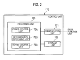
- the control unit 170 includes a communication unit 171, a storage unit 172, and a process unit 173.
- the communication unit 171 communicates with each function unit in the power conditioner 100 via the control signal line.
- the communication unit 171 can also communicate with other devices, e.g., the load equipment, via the external I/F 150.
- the storage unit 172 stores programs executed by the process unit 173, and is used also as a working memory during the execution of the program in the process unit 173.
- the process unit 173 controls each function in the control unit 170.
- a process unit 173 includes a power controller 173A, a determination processing unit 173B, and a supply control unit 173C.
- the power controller 173A controls an operational status of the power conditioner 100. For example, when the power controller 173A receives an instruction to execute the interconnection operation or the stand-alone operation from the external I/F 150 via the communication unit 171, the power controller 173A notifies to the determination processing unit 173B and the supply control unit 173C so as to switch to the interconnection operation or the stand-alone operation in response to the instruction. Note that the instructions to execute the interconnection operation or the stand-alone operation is may be input by the user from the external I/F 150 so that the user may switch manually and directly therebetween.
- the determination processing unit 173B executes an output determination process for determining whether or not the power supplied from the photovoltaic cell 20 satisfies power required for operating the load equipment at the time of the stand-alone operation.
- the present embodiment describes the power supplied from the photovoltaic cell 20 to the load equipment 30 as a supplied power. That is, the power output from the photovoltaic cell 20, and then supplied from the stand-alone system side output unit 132 to the load equipment 30 after being converted into AC is described as a supplied power.
- power required for a normal operation of the load equipment 30 is described as a demanded power. Note that the demanded power may be power required for a normal operation of one load equipment 30, or may be a total value of power required for normal operations of a plurality of the load equipments 30.
- the determination processing unit 173B stores beforehand a voltage value (hereinafter, adjusted voltage value) adjusted by a constant voltage control executed by the DC/AC converter 111. Moreover, the determination processing unit 173B obtains a voltage value (hereinafter, measured voltage value) measured by the measuring unit 140 when the stand-alone operation is started. The determination processing unit 173B determines whether or not the measured voltage value is smaller than the adjusted voltage value.
- the determination processing unit 173B determines that the supplied power satisfies the demanded power if determining that the measured voltage value is not smaller than the adjusted voltage value. On the other hand, the determination processing unit 173B determines that the supplied power does not satisfy the demanded power if determining that the measured voltage value is smaller than the adjusted voltage value. Moreover, the determination processing unit 173B notifies the determined result to the supply control unit 173C.
- the supply control unit 173C continues the stand-alone operation if it is determined that the supplied power satisfies the demanded power, but suspends the stand-alone operation if it is determined that the supplied power does not satisfy the demanded power.
- the supply control unit 173C receives a notice that the supplied power satisfies the demanded power from the determination processing unit 173B as a determined result, the supply control unit 173C performs particularly no operation, but continues the stand-alone operation. On the other hand, the supply control unit 173C instructs to the stand-alone relay 122 so as to disconnect therebetween, if a notice that the supplied power does not satisfy the demanded power is received from the determination processing unit 173B as a determined result. That is, the supply control unit 173C suspends the stand-alone operation.
- the supply control unit 173C increments by 1 a count number indicating the number of times of the determination that the supplied power does not satisfy the demanded power.
- the count number indicates the number of times of continuously determining that the supplied power does not satisfy the demanded power.
- the supply control unit 173C determines whether or not the incremented count number is equal to or greater than a predetermined threshold value (predetermined number of times). If the supply control unit 173C determines that the count number is smaller than the threshold value, the supply control unit 173C notifies the determined result to the determination processing unit 173B.
- the determination processing unit 173B which received this notice repeats the output determination process at predetermined intervals. That is, after suspending the stand-alone operation, the determination processing unit 173B re-executes the stand-alone operation at predetermined intervals, and then determines whether or not the supplied power satisfies the demanded power. However, the output determination process may be executed at random.
- the supply control unit 173C determines that the incremented count number is equal to or greater than the threshold value, the supply control unit 173C notifies the determined result to the determination processing unit 173B.
- the determination processing unit 173B which received this notice stops re-execution of the stand-alone operation. That is, the determination processing unit 173B also stops the output determination process. In this manner, the determination processing unit 173B stops re-execution of the stand-alone operation, if the number of times of continuously determining that the supplied power does not satisfy the demanded power reaches the predetermined number of times. Note that the determination processing unit 173B can set up and input beforehand the aforementioned predetermined number of times, on the basis of a user's input.
- Fig. 3 is a sequence diagram showing an operation executed by the power conditioner 100.
- step S101 the supply control unit 173C resets the count number for indicating the number of times of determining that the supplied power does not satisfy the demanded power before the stand-alone operation is a started, in the power conditioner 100.
- step S102 the determination processing unit 173B contacts the power controller 173A to determine whether or not the stand-alone operation should be executed. For example, the determination processing unit 173B determines whether or not an instruction to execute the stand-alone operation is input by the user. Note that the determination processing unit 173B repeats the operation of steps S101 to S102 if it is determined to not execute the stand-alone operation.
- step S103 the determination processing unit 173B stands by for a first time period if it is determined to execute the stand-alone operation. At this point, the determination processing unit 173B stands by for only the first time period, thereby adjusting the intervals (predetermined intervals) at the time of repeating the operation shown in steps S101 to S109 in next operations. Although it is assumed that the first time period is approximately 10 to 20 seconds, it is not limited to this example.
- step S104 the determination processing unit 173B instructs to connect therebetween to the stand-alone relay 122. Accordingly, the stand-alone operation for supplying the power from the photovoltaic cell 20 to the load equipment 30 is executed.
- step S105 the determination processing unit 173B stands by for a second time period at the time of the stand-alone operation. Note that the determination processing unit 173B stands by for only the second time period, thereby obtaining a time period where the power supplied to the load equipment 30 is stabilized, i.e., a time period where the power consumed by the operation of the load equipment 30 is stabilized. Although it is assumed that the second time period is approximately 5 to 20 seconds, it is not limited to this example.
- step S106 the determination processing unit 173B determines whether or not the supplied power from the photovoltaic cell 20 satisfies the demanded power required for operating the load equipment, at the time of the stand-alone operation. Specifically, the determination processing unit 173B obtains the measured voltage value measured by the measuring unit 140, after a lapse of the second time period from a start of the stand-alone operation.
- the determination processing unit 173B determines whether or not the measured voltage value measured by the measuring unit 140 is smaller than the adjusted voltage value adjusted by the constant voltage control of the DC/AC converter 111. For example, if the adjusted voltage value is 100V, the determination processing unit 173B determines whether or not the measured voltage value is smaller than 100V.
- the determination processing unit 173B determines that the supplied power satisfies the demanded power, and then repeats the operation of step S101. On the other hand, the determination processing unit 173B determines that the supplied power does not satisfy the demanded power, if the measured voltage value is smaller than 100V. Moreover, the determination processing unit 173B notifies the determined result to the supply control unit 173C.
- step S107 the supply control unit 173C suspends the stand-alone operation, if it is determined that the supplied power does not satisfy the demanded power.
- the supply control unit 173C instructs to the stand-alone relay 122 so as to disconnect therebetween, if a notice that the supplied power does not satisfy the demanded power is received from the determination processing unit 173B. Moreover, if the supply control unit 173C receives a notice that the supplied power satisfies the demanded power from the determination processing unit 173B, the supply control unit 173C performs particularly no operation, but continues the stand-alone operation.
- step S108 the supply control unit 173C increments by 1 the count number indicating the number of times of determining that the supplied power does not satisfy the demanded power.
- the count number is incremented every time the operation of steps S102 to S108 is repeated, without being reset in step S101. That is, the count number indicates the number of times of continuously determining that the supplied power does not satisfy the demanded power.
- step S109 the supply control unit 173C determines whether or not the incremented count number is equal to or greater than the predetermined threshold value (predetermined number of times). If the supply control unit 173C determines that the count number is smaller than the threshold value, the supply control unit 173C notifies the determined result to the determination processing unit 173B.
- the determination processing unit 173B which received this notice repeats the operation of step S102. That is, in step S107, after suspending the stand-alone operation, the determination processing unit 173B re-executes the stand-alone operation at the predetermined intervals to repeat the output determination process. However, the output determination process may be executed at random.
- step S110 if the supply control unit 173C determines that the incremented count number is equal to or greater than the threshold value, the supply control unit 173C notifies the determined result to the determination processing unit 173B.
- the determination processing unit 173B which received this notice stops the execution of the stand-alone operation. That is, the determination processing unit 173B stops re-executing of the stand-alone operation. In this manner, the determination processing unit 173B stops re-execution of the stand-alone operation, if the number of times of continuously determining that the supplied power does not satisfy the demanded power reaches the predetermined number of times.
- the power conditioner 100 executes the output determination process for determining whether or not the supplied power from the photovoltaic cell 20 satisfies the demanded power required for operating the load equipment 30.
- the power conditioner 100 suspends the stand-alone operation, if it is determined that the supplied power does not satisfy the demanded power.
- the power conditioner 100 re-executes the stand-alone operation to repeat the output determination process even after the stand-alone operation is suspended.
- the power conditioner 100 stops re-executing of the stand-alone operation, if the number of times of continuously determining that the supplied power does not satisfy the demanded power becomes equal to or greater than the threshold value (predetermined number of times) as a result of the repeat execution of the output determination process.
- the power conditioner 100 based on the present embodiment, if the number of times of continuously determining that the supplied power does not satisfy the demanded power becomes equal to or greater than the threshold value, the power conditioner 100 stops re-executing of the stand-alone operation without endlessly repeating the stand-alone operation and the output determination process.
- the power conditioner 100 can prevent from the stand-alone operation being continued to be executed, if the time period when the supplied power does not satisfy the demanded power becomes a long period of time, and a user leaves the load equipment in the state where the load equipment is turned ON.
- the power conditioner 100 As mentioned above, according to the power conditioner 100 based on the present embodiment, at the time of the stand-alone operation, it is possible to prevent an operation of the load equipment at an unintended timing.
- the determination processing unit 173B is configured to stop re-executing of the stand-alone operation, if the number of times, i.e., the count number, of continuously determining that the supplied power does not satisfy the demanded power is equal to or greater than the threshold value.
- the determination processing unit 173B stops re-executing of the stand-alone operation, if a predetermined period elapses without determining that the supplied power satisfies the demanded power, since it is determined that the supplied power does not satisfy the demanded power after suspending the stand-alone operation.
- the determination processing unit 173B determines that the supplied power does not satisfy the demanded power at the time of the stand-alone operation, the determination processing unit 173B notifies the determined result to the supply control unit 173C.
- the supply control unit 173C if the supply control unit 173C receives a notice that the supplied power does not satisfy the demanded power as the determined result, the supply control unit 173C instructs to disconnect therebetween to the stand-alone relay 122 to suspend the stand-alone operation. At this time, the supply control unit 173C drives a timer. Then, the supply control unit 173C determines whether or not a timer value is equal to or greater than a predetermined threshold value (predetermined period). If the supply control unit 173C determines that the timer value is smaller than the threshold value, the supply control unit 173C notifies the determined result to the determination processing unit 173B.
- a predetermined threshold value predetermined period
- the determination processing unit 173B which received this notice executes the stand-alone operation at predetermined intervals to repeat the output determination process. That is, after suspending the stand-alone operation, the determination processing unit 173B re-executes the stand-alone operation at predetermined intervals, and then determines whether or not the supplied power satisfies the demanded power.
- the supply control unit 173C determines that the timer value is equal to or greater than the threshold value, the supply control unit 173C notifies the determined result to the determination processing unit 173B.
- the determination processing unit 173B which received this notice stops re-execution of the stand-alone operation.
- the determination processing unit 173B also stops the execution of the output determination process.
- the timer value is reset and the timer is stopped if the determination processing unit 173B determines that the supplied power satisfies the demanded power. In this manner, the determination processing unit 173B stops re-executing of the stand-alone operation, if a predetermined period (threshold value) elapses without determining that the supplied power satisfies the demanded power after it is determined that the supplied power does not satisfy the demanded power.
- Fig. 4 is a sequence diagram showing an operation of the power conditioner 100 according to the present embodiment.
- step S201 before starting the stand-alone operation, the supply control unit 173C resets a timer value, and stops the timer in the power conditioner 100.
- steps S202 to S207 is the same as the operation in the first embodiment mentioned above, the description thereof is omitted.
- step S208 the supply control unit 173C drives the timer, if the determination processing unit 173B determines that the supplied power does not satisfy the demanded power. Note that if the timer has already been driven, the timer is continued to be activated. In this case, the timer value is incremented as repeating the operation of steps S102 to S108, without resetting and stopping the timer in step S101. That is, the timer value indicates a time period which elapses without determining that the supplied power satisfies the demanded power, after determining that the supplied power does not satisfy the demanded power.
- step S209 the supply control unit 173C determines whether or not the timer value is equal to or greater than the predetermined threshold value. If the supply control unit 173C determines that the timer value is smaller than the threshold value, the supply control unit 173C notifies the determined result to the determination processing unit 173B.
- the determination processing unit 173B which received this notice repeats the operation of step S202. That is, after suspending the stand-alone operation in step S207, the determination processing unit 173B re-executes the stand-alone operation at the predetermined intervals, and then determines whether or not the supplied power satisfies the demanded power.
- step S210 if the supply control unit 173C determines that the timer value is equal to or greater than the threshold value, the supply control unit 173C notifies the determined result to the determination processing unit 173B.
- the determination processing unit 173B which received this notice stops re-execution of the stand-alone operation. Note that the determination processing unit 173B also stops the output determination process. In this manner, the determination processing unit 173B stops re-executing of the stand-alone operation, if a predetermined period (threshold value) elapses without determining that the supplied power satisfies the demanded power after it is determined that the supplied power does not satisfy the demanded power.
- the power conditioner 100 repeatedly executes the output determination process for determining whether or not the supplied power from the photovoltaic cell 20 satisfies the demanded power required for operating the load equipment 30.
- the power conditioner 100 stops re-executing of the stand-alone operation, if a predetermined period (threshold value) elapses without determining that the supplied power satisfies the demanded power after it is determined that the supplied power does not satisfy the demanded power.
- the power conditioner 100 based on the present embodiment, if the predetermined period elapses without the supplied power satisfying the demanded power, the power conditioner 100 stops re-executing of the stand-alone operation without endlessly repeating the stand-alone operation and the output determination process.
- the power conditioner 100 can prevent from the stand-alone operation being continued to be executed, if the time period when the supplied power does not satisfy the demanded power becomes a long period of time, and a user leaves the load equipment in the state where the load equipment is turned ON.
- the power conditioner 100 As mentioned above, according to the power conditioner 100 based on the present embodiment, at the time of the stand-alone operation, it is possible to prevent an operation of the load equipment at the unintended timing.
- a point of including a power management device 200 are the principal point of difference with the power control system 1 according to the first to second embodiments mentioned above. Note that it is assumed that the power management device 200 is a device called Home Energy Management System (HEMS) in smart grid technology.
- HEMS Home Energy Management System
- the power conditioner 100 communicates with the power management device 200.
- the power management device 200 is connected to a load equipment 30, and an electric socket 50 for supplying power to the load equipment 30.
- the load equipment 30 can control to start, stop, etc., an operation in response to instructions from the power management device 200.
- the electric socket 50 can connect or disconnect between a stand-alone system line 12 and the load equipment 30 in response to the instructions from the power management device 200.
- the power management device 200 stores type information indicating a type of load equipment 30 (electric heaters, televisions, radios, etc.) provided at the consumer site, and a demanded power required for operating the load equipment 30.
- type information indicating a type of load equipment 30 (electric heaters, televisions, radios, etc.) provided at the consumer site, and a demanded power required for operating the load equipment 30.
- the determination processing unit 173B obtains the type information on the load equipment 30 from the power management device 200, if the supply control unit 173C determines that the count number is equal to or greater than the threshold value, or determines that the timer value is equal to or greater than the threshold value. Moreover, the determination processing unit 173B determines whether or not the load equipment 30 is a specific device on the basis of the type information, when obtaining the type information on the load equipment 30.
- the specific device is a load equipment which may have a harmful effect, e.g., an accident, at the time of user's absence, and electric heaters, televisions, radios, etc., are listed as an example.
- the determination processing unit 173B determines that the load equipment 30 is the specific device, and then stops re-executing of the stand-alone operation. That is, the determination processing unit 173B executes the operation shown in the first to second embodiments mentioned above, and then stops re-executing of the stand-alone operation.
- the determination processing unit 173B determines that the load equipments 30 are not specific device, and then re-executes the operation of Figs. 3 to 4 . That is, the determination processing unit 173B re-executes the stand-alone operation.
- the determination processing unit 173B may stop re-executing of the stand-alone operation in consideration of safety, if the specific device and a device other than the specific device are coexisted as the load equipments 30. Moreover, if the specific device and a device other than the specific device are coexisted as the load equipments 30, the determination processing unit 173B may instruct to the power management device 200 to stop only operation of the specific device, and then may re-execute the stand-alone operation. At this time, the power management device 200 may instruct to the load equipment 30 which is the specific device to stop the operation, and may instruct to disconnection therebetween to the electric socket 50 connected to the load equipment 30 which is the specific device.
- the stand-alone operation is stopped after determining whether or not the load equipment 30 is the specific device, without immediately stopping re-executing of the stand-alone operation.
- the power conditioner 100 re-executes the stand-alone operation, if the load equipment 30 is not the specific device. Accordingly, according to the power conditioner 100 based on the present embodiment, at the time of a stand-alone operation, it is possible to prevent an operation of the load equipment at the unintended timing, and it is possible to operate the load equipment 30 while executing the stand-alone operation as much as possible.
- the photovoltaic cell 20 listed as an example has been described as distributed power supply, the present invention can be similarly applied to a case of using another electronic supplied power to which power output is changed, e.g., a wind power generator.
- the adjusted voltage value has been described as the voltage value adjusted by the constant voltage control, the adjusted voltage value may be a voltage value arbitrarily set up.
- control unit 170 in the power conditioner 100 may be provided in the power management device 200, or may be provided in various systems in the smart grid technology, e.g., Building Energy Management System (BEMS) etc.
- BEMS Building Energy Management System
- the weather does not serve over a long term, sufficient power may be no longer supplied to the load equipment over a long period of time from the distributed power supply.
- the load equipment cannot execute the correct operation at the time of the stand-alone operation, if the load equipment is an electric heater etc., for example, the electric heater cannot sufficiently generate heat.
- the load equipment is radio etc., sounds may not come out therefrom.
- the power control apparatus continues to execute the output determination process at the predetermined intervals also in such a situation, if the weather serves and the supplied power from the distributed power supply comes to satisfy the demanded power for the load equipment, the load equipment will start the correct operation.
- the load equipment may generate heat at the time of absence of user. If the load equipment is television or radio, sounds may come out therefrom in a situation to which a user does not view and listen, and thereby it may generate noise in the neighborhood. That is, in the power control apparatus mentioned above, the load equipment may be operated at the unintended timing at the time of the stand-alone operation.
- the power control apparatus and the power control method are provided which can prevent from the operation by the load equipment at the unintended timing.
Landscapes
- Engineering & Computer Science (AREA)
- Power Engineering (AREA)
- Business, Economics & Management (AREA)
- Emergency Management (AREA)
- Supply And Distribution Of Alternating Current (AREA)
Applications Claiming Priority (2)
| Application Number | Priority Date | Filing Date | Title |
|---|---|---|---|
| JP2011116279 | 2011-05-24 | ||
| PCT/JP2012/063331 WO2012161255A1 (fr) | 2011-05-24 | 2012-05-24 | Dispositif de commande d'alimentation et procédé de commande d'alimentation |
Publications (3)
| Publication Number | Publication Date |
|---|---|
| EP2717410A1 true EP2717410A1 (fr) | 2014-04-09 |
| EP2717410A4 EP2717410A4 (fr) | 2015-07-22 |
| EP2717410B1 EP2717410B1 (fr) | 2016-08-24 |
Family
ID=47217327
Family Applications (1)
| Application Number | Title | Priority Date | Filing Date |
|---|---|---|---|
| EP12789252.9A Not-in-force EP2717410B1 (fr) | 2011-05-24 | 2012-05-24 | Dispositif de commande d'alimentation et procédé de commande d'alimentation |
Country Status (4)
| Country | Link |
|---|---|
| US (1) | US9391460B2 (fr) |
| EP (1) | EP2717410B1 (fr) |
| JP (1) | JP5647731B2 (fr) |
| WO (1) | WO2012161255A1 (fr) |
Cited By (1)
| Publication number | Priority date | Publication date | Assignee | Title |
|---|---|---|---|---|
| GB2534676A (en) * | 2014-12-12 | 2016-08-03 | Hickson Ian | Electrical power control device and system |
Families Citing this family (6)
| Publication number | Priority date | Publication date | Assignee | Title |
|---|---|---|---|---|
| JP2015015782A (ja) * | 2013-07-03 | 2015-01-22 | サンケン電気株式会社 | 系統連系インバータ装置 |
| WO2015093494A1 (fr) * | 2013-12-16 | 2015-06-25 | 京セラ株式会社 | Dispositif de régulation de puissance, dispositif de commande d'équipements et procédé associé |
| JP6422247B2 (ja) * | 2014-06-30 | 2018-11-14 | 三菱電機株式会社 | パワーコンディショナ |
| JP2017118598A (ja) * | 2015-12-21 | 2017-06-29 | 株式会社デンソー | 電力供給システム |
| US10700527B2 (en) * | 2016-03-25 | 2020-06-30 | Sharp Kabushiki Kaisha | Power generation system, power conditioner, power control device, power control method, and power control program |
| JP6996366B2 (ja) * | 2018-03-13 | 2022-01-17 | オムロン株式会社 | 変換装置及びハイブリット電源システム |
Family Cites Families (8)
| Publication number | Priority date | Publication date | Assignee | Title |
|---|---|---|---|---|
| JPH09149554A (ja) * | 1995-11-20 | 1997-06-06 | Sanyo Electric Co Ltd | 太陽光発電装置 |
| JPH1028330A (ja) * | 1996-07-08 | 1998-01-27 | Nissin Electric Co Ltd | 分散電源用系統連系システム |
| JPH10336916A (ja) | 1997-05-29 | 1998-12-18 | Kyocera Corp | 非常用電源システム |
| JP2003319561A (ja) * | 2002-04-23 | 2003-11-07 | Matsushita Electric Works Ltd | 発電システム |
| CN101765959B (zh) * | 2007-05-08 | 2015-04-15 | 美国电力转换有限公司 | 交流电源能量管理 |
| DE102009040090A1 (de) * | 2009-09-04 | 2011-03-10 | Voltwerk Electronics Gmbh | Inseleinheit für ein Energienetz mit einer Steuereinheit zum Steuern eines Energieflusses zwischen der Energieerzeugungseinheit, der Energiespeichereinheit, der Lasteinheit und/oder dem Energienetz |
| JP5045736B2 (ja) | 2009-12-04 | 2012-10-10 | 株式会社豊田自動織機 | 産業車両の走行制御装置 |
| KR101174891B1 (ko) * | 2010-06-01 | 2012-08-17 | 삼성에스디아이 주식회사 | 전력 저장 시스템 및 그 제어방법 |
-
2012
- 2012-05-24 EP EP12789252.9A patent/EP2717410B1/fr not_active Not-in-force
- 2012-05-24 WO PCT/JP2012/063331 patent/WO2012161255A1/fr not_active Ceased
- 2012-05-24 JP JP2013516432A patent/JP5647731B2/ja active Active
- 2012-05-24 US US14/119,380 patent/US9391460B2/en active Active
Cited By (1)
| Publication number | Priority date | Publication date | Assignee | Title |
|---|---|---|---|---|
| GB2534676A (en) * | 2014-12-12 | 2016-08-03 | Hickson Ian | Electrical power control device and system |
Also Published As
| Publication number | Publication date |
|---|---|
| US20140097695A1 (en) | 2014-04-10 |
| EP2717410A4 (fr) | 2015-07-22 |
| WO2012161255A1 (fr) | 2012-11-29 |
| US9391460B2 (en) | 2016-07-12 |
| JP5647731B2 (ja) | 2015-01-07 |
| EP2717410B1 (fr) | 2016-08-24 |
| JPWO2012161255A1 (ja) | 2014-07-31 |
Similar Documents
| Publication | Publication Date | Title |
|---|---|---|
| EP2717410B1 (fr) | Dispositif de commande d'alimentation et procédé de commande d'alimentation | |
| EP2701264B1 (fr) | Dispositif de commande, système de commande de puissance et procédé de commande de puissance | |
| US9651971B2 (en) | Control device, power control system, and power control method | |
| JP5655167B2 (ja) | 電力管理装置およびプログラム | |
| CN105379049B (zh) | 电力控制器、电力控制方法以及电力控制系统 | |
| JP2011078215A (ja) | 配電システム | |
| EP2487770A1 (fr) | Système d'alimentation électrique | |
| EP2693590A1 (fr) | Système de production électrique décentralisée et son procédé de fonctionnement | |
| JP2024009124A (ja) | 電力制御装置、蓄電池システム、蓄電池の充電電力制御方法及びプログラム | |
| JP6574696B2 (ja) | 電力制御装置、電力制御方法及び燃料電池システム | |
| JP5952069B2 (ja) | 消費監視システム | |
| JP6141631B2 (ja) | 電力供給システム | |
| JP2015154616A (ja) | 制御装置、制御方法、プログラム、および電力制御システム | |
| JP2013121255A (ja) | 電力供給システム | |
| JP7401846B2 (ja) | ポジワット取引支援装置およびポジワット取引方法 | |
| JP2013165577A (ja) | パワーコンディショナ、発電システムおよび電流抑制回路 | |
| US20150073616A1 (en) | Power supply device, power supply system, and electronic device | |
| US20220376502A1 (en) | Method and apparatus for controlling loads connected to a distributed energy generation system | |
| JP2017070063A (ja) | 電力制御装置 | |
| JP2015080375A (ja) | 電力変換装置 | |
| JPWO2016185759A1 (ja) | 機器制御システムおよび制御方法 | |
| JP3242499U (ja) | 電力制御装置 | |
| JP2020054194A (ja) | 蓄電システム、制御装置、および制御方法 | |
| JP6990829B2 (ja) | 電力変換装置 | |
| JP2024086108A (ja) | 蓄電池管理システム |
Legal Events
| Date | Code | Title | Description |
|---|---|---|---|
| PUAI | Public reference made under article 153(3) epc to a published international application that has entered the european phase |
Free format text: ORIGINAL CODE: 0009012 |
|
| 17P | Request for examination filed |
Effective date: 20131209 |
|
| AK | Designated contracting states |
Kind code of ref document: A1 Designated state(s): AL AT BE BG CH CY CZ DE DK EE ES FI FR GB GR HR HU IE IS IT LI LT LU LV MC MK MT NL NO PL PT RO RS SE SI SK SM TR |
|
| DAX | Request for extension of the european patent (deleted) | ||
| RA4 | Supplementary search report drawn up and despatched (corrected) |
Effective date: 20150622 |
|
| RIC1 | Information provided on ipc code assigned before grant |
Ipc: H02J 3/38 20060101AFI20150616BHEP Ipc: H02J 9/06 20060101ALI20150616BHEP Ipc: H02J 5/00 20060101ALI20150616BHEP |
|
| GRAP | Despatch of communication of intention to grant a patent |
Free format text: ORIGINAL CODE: EPIDOSNIGR1 |
|
| RIC1 | Information provided on ipc code assigned before grant |
Ipc: H02J 9/06 20060101ALI20160203BHEP Ipc: H02J 3/38 20060101AFI20160203BHEP Ipc: H02J 5/00 20160101ALI20160203BHEP |
|
| INTG | Intention to grant announced |
Effective date: 20160308 |
|
| GRAS | Grant fee paid |
Free format text: ORIGINAL CODE: EPIDOSNIGR3 |
|
| GRAA | (expected) grant |
Free format text: ORIGINAL CODE: 0009210 |
|
| AK | Designated contracting states |
Kind code of ref document: B1 Designated state(s): AL AT BE BG CH CY CZ DE DK EE ES FI FR GB GR HR HU IE IS IT LI LT LU LV MC MK MT NL NO PL PT RO RS SE SI SK SM TR |
|
| REG | Reference to a national code |
Ref country code: GB Ref legal event code: FG4D |
|
| REG | Reference to a national code |
Ref country code: CH Ref legal event code: EP |
|
| REG | Reference to a national code |
Ref country code: AT Ref legal event code: REF Ref document number: 823848 Country of ref document: AT Kind code of ref document: T Effective date: 20160915 |
|
| REG | Reference to a national code |
Ref country code: IE Ref legal event code: FG4D |
|
| REG | Reference to a national code |
Ref country code: DE Ref legal event code: R096 Ref document number: 602012022271 Country of ref document: DE |
|
| REG | Reference to a national code |
Ref country code: LT Ref legal event code: MG4D |
|
| REG | Reference to a national code |
Ref country code: NL Ref legal event code: MP Effective date: 20160824 |
|
| REG | Reference to a national code |
Ref country code: AT Ref legal event code: MK05 Ref document number: 823848 Country of ref document: AT Kind code of ref document: T Effective date: 20160824 |
|
| PG25 | Lapsed in a contracting state [announced via postgrant information from national office to epo] |
Ref country code: RS Free format text: LAPSE BECAUSE OF FAILURE TO SUBMIT A TRANSLATION OF THE DESCRIPTION OR TO PAY THE FEE WITHIN THE PRESCRIBED TIME-LIMIT Effective date: 20160824 Ref country code: FI Free format text: LAPSE BECAUSE OF FAILURE TO SUBMIT A TRANSLATION OF THE DESCRIPTION OR TO PAY THE FEE WITHIN THE PRESCRIBED TIME-LIMIT Effective date: 20160824 Ref country code: NO Free format text: LAPSE BECAUSE OF FAILURE TO SUBMIT A TRANSLATION OF THE DESCRIPTION OR TO PAY THE FEE WITHIN THE PRESCRIBED TIME-LIMIT Effective date: 20161124 Ref country code: HR Free format text: LAPSE BECAUSE OF FAILURE TO SUBMIT A TRANSLATION OF THE DESCRIPTION OR TO PAY THE FEE WITHIN THE PRESCRIBED TIME-LIMIT Effective date: 20160824 Ref country code: LT Free format text: LAPSE BECAUSE OF FAILURE TO SUBMIT A TRANSLATION OF THE DESCRIPTION OR TO PAY THE FEE WITHIN THE PRESCRIBED TIME-LIMIT Effective date: 20160824 Ref country code: NL Free format text: LAPSE BECAUSE OF FAILURE TO SUBMIT A TRANSLATION OF THE DESCRIPTION OR TO PAY THE FEE WITHIN THE PRESCRIBED TIME-LIMIT Effective date: 20160824 Ref country code: IT Free format text: LAPSE BECAUSE OF FAILURE TO SUBMIT A TRANSLATION OF THE DESCRIPTION OR TO PAY THE FEE WITHIN THE PRESCRIBED TIME-LIMIT Effective date: 20160824 |
|
| PG25 | Lapsed in a contracting state [announced via postgrant information from national office to epo] |
Ref country code: PT Free format text: LAPSE BECAUSE OF FAILURE TO SUBMIT A TRANSLATION OF THE DESCRIPTION OR TO PAY THE FEE WITHIN THE PRESCRIBED TIME-LIMIT Effective date: 20161226 Ref country code: AT Free format text: LAPSE BECAUSE OF FAILURE TO SUBMIT A TRANSLATION OF THE DESCRIPTION OR TO PAY THE FEE WITHIN THE PRESCRIBED TIME-LIMIT Effective date: 20160824 Ref country code: LV Free format text: LAPSE BECAUSE OF FAILURE TO SUBMIT A TRANSLATION OF THE DESCRIPTION OR TO PAY THE FEE WITHIN THE PRESCRIBED TIME-LIMIT Effective date: 20160824 Ref country code: ES Free format text: LAPSE BECAUSE OF FAILURE TO SUBMIT A TRANSLATION OF THE DESCRIPTION OR TO PAY THE FEE WITHIN THE PRESCRIBED TIME-LIMIT Effective date: 20160824 Ref country code: GR Free format text: LAPSE BECAUSE OF FAILURE TO SUBMIT A TRANSLATION OF THE DESCRIPTION OR TO PAY THE FEE WITHIN THE PRESCRIBED TIME-LIMIT Effective date: 20161125 Ref country code: SE Free format text: LAPSE BECAUSE OF FAILURE TO SUBMIT A TRANSLATION OF THE DESCRIPTION OR TO PAY THE FEE WITHIN THE PRESCRIBED TIME-LIMIT Effective date: 20160824 |
|
| PG25 | Lapsed in a contracting state [announced via postgrant information from national office to epo] |
Ref country code: RO Free format text: LAPSE BECAUSE OF FAILURE TO SUBMIT A TRANSLATION OF THE DESCRIPTION OR TO PAY THE FEE WITHIN THE PRESCRIBED TIME-LIMIT Effective date: 20160824 Ref country code: EE Free format text: LAPSE BECAUSE OF FAILURE TO SUBMIT A TRANSLATION OF THE DESCRIPTION OR TO PAY THE FEE WITHIN THE PRESCRIBED TIME-LIMIT Effective date: 20160824 |
|
| REG | Reference to a national code |
Ref country code: DE Ref legal event code: R097 Ref document number: 602012022271 Country of ref document: DE |
|
| PG25 | Lapsed in a contracting state [announced via postgrant information from national office to epo] |
Ref country code: SK Free format text: LAPSE BECAUSE OF FAILURE TO SUBMIT A TRANSLATION OF THE DESCRIPTION OR TO PAY THE FEE WITHIN THE PRESCRIBED TIME-LIMIT Effective date: 20160824 Ref country code: DK Free format text: LAPSE BECAUSE OF FAILURE TO SUBMIT A TRANSLATION OF THE DESCRIPTION OR TO PAY THE FEE WITHIN THE PRESCRIBED TIME-LIMIT Effective date: 20160824 Ref country code: CZ Free format text: LAPSE BECAUSE OF FAILURE TO SUBMIT A TRANSLATION OF THE DESCRIPTION OR TO PAY THE FEE WITHIN THE PRESCRIBED TIME-LIMIT Effective date: 20160824 Ref country code: BE Free format text: LAPSE BECAUSE OF FAILURE TO SUBMIT A TRANSLATION OF THE DESCRIPTION OR TO PAY THE FEE WITHIN THE PRESCRIBED TIME-LIMIT Effective date: 20160824 Ref country code: BG Free format text: LAPSE BECAUSE OF FAILURE TO SUBMIT A TRANSLATION OF THE DESCRIPTION OR TO PAY THE FEE WITHIN THE PRESCRIBED TIME-LIMIT Effective date: 20161124 Ref country code: SM Free format text: LAPSE BECAUSE OF FAILURE TO SUBMIT A TRANSLATION OF THE DESCRIPTION OR TO PAY THE FEE WITHIN THE PRESCRIBED TIME-LIMIT Effective date: 20160824 Ref country code: PL Free format text: LAPSE BECAUSE OF FAILURE TO SUBMIT A TRANSLATION OF THE DESCRIPTION OR TO PAY THE FEE WITHIN THE PRESCRIBED TIME-LIMIT Effective date: 20160824 |
|
| PLBE | No opposition filed within time limit |
Free format text: ORIGINAL CODE: 0009261 |
|
| STAA | Information on the status of an ep patent application or granted ep patent |
Free format text: STATUS: NO OPPOSITION FILED WITHIN TIME LIMIT |
|
| 26N | No opposition filed |
Effective date: 20170526 |
|
| PG25 | Lapsed in a contracting state [announced via postgrant information from national office to epo] |
Ref country code: LU Free format text: LAPSE BECAUSE OF NON-PAYMENT OF DUE FEES Effective date: 20170531 Ref country code: SI Free format text: LAPSE BECAUSE OF FAILURE TO SUBMIT A TRANSLATION OF THE DESCRIPTION OR TO PAY THE FEE WITHIN THE PRESCRIBED TIME-LIMIT Effective date: 20160824 |
|
| REG | Reference to a national code |
Ref country code: CH Ref legal event code: PL |
|
| GBPC | Gb: european patent ceased through non-payment of renewal fee |
Effective date: 20170524 |
|
| PG25 | Lapsed in a contracting state [announced via postgrant information from national office to epo] |
Ref country code: MC Free format text: LAPSE BECAUSE OF FAILURE TO SUBMIT A TRANSLATION OF THE DESCRIPTION OR TO PAY THE FEE WITHIN THE PRESCRIBED TIME-LIMIT Effective date: 20160824 |
|
| REG | Reference to a national code |
Ref country code: IE Ref legal event code: MM4A |
|
| PG25 | Lapsed in a contracting state [announced via postgrant information from national office to epo] |
Ref country code: LI Free format text: LAPSE BECAUSE OF NON-PAYMENT OF DUE FEES Effective date: 20170531 Ref country code: CH Free format text: LAPSE BECAUSE OF NON-PAYMENT OF DUE FEES Effective date: 20170531 |
|
| REG | Reference to a national code |
Ref country code: FR Ref legal event code: ST Effective date: 20180131 |
|
| PG25 | Lapsed in a contracting state [announced via postgrant information from national office to epo] |
Ref country code: LU Free format text: LAPSE BECAUSE OF NON-PAYMENT OF DUE FEES Effective date: 20170524 |
|
| PG25 | Lapsed in a contracting state [announced via postgrant information from national office to epo] |
Ref country code: IE Free format text: LAPSE BECAUSE OF NON-PAYMENT OF DUE FEES Effective date: 20170524 Ref country code: GB Free format text: LAPSE BECAUSE OF NON-PAYMENT OF DUE FEES Effective date: 20170524 |
|
| PG25 | Lapsed in a contracting state [announced via postgrant information from national office to epo] |
Ref country code: FR Free format text: LAPSE BECAUSE OF NON-PAYMENT OF DUE FEES Effective date: 20170531 |
|
| PG25 | Lapsed in a contracting state [announced via postgrant information from national office to epo] |
Ref country code: MT Free format text: LAPSE BECAUSE OF NON-PAYMENT OF DUE FEES Effective date: 20170524 |
|
| PG25 | Lapsed in a contracting state [announced via postgrant information from national office to epo] |
Ref country code: AL Free format text: LAPSE BECAUSE OF FAILURE TO SUBMIT A TRANSLATION OF THE DESCRIPTION OR TO PAY THE FEE WITHIN THE PRESCRIBED TIME-LIMIT Effective date: 20160824 |
|
| PG25 | Lapsed in a contracting state [announced via postgrant information from national office to epo] |
Ref country code: HU Free format text: LAPSE BECAUSE OF FAILURE TO SUBMIT A TRANSLATION OF THE DESCRIPTION OR TO PAY THE FEE WITHIN THE PRESCRIBED TIME-LIMIT; INVALID AB INITIO Effective date: 20120524 |
|
| PG25 | Lapsed in a contracting state [announced via postgrant information from national office to epo] |
Ref country code: CY Free format text: LAPSE BECAUSE OF NON-PAYMENT OF DUE FEES Effective date: 20160824 |
|
| PG25 | Lapsed in a contracting state [announced via postgrant information from national office to epo] |
Ref country code: MK Free format text: LAPSE BECAUSE OF FAILURE TO SUBMIT A TRANSLATION OF THE DESCRIPTION OR TO PAY THE FEE WITHIN THE PRESCRIBED TIME-LIMIT Effective date: 20160824 |
|
| PG25 | Lapsed in a contracting state [announced via postgrant information from national office to epo] |
Ref country code: TR Free format text: LAPSE BECAUSE OF FAILURE TO SUBMIT A TRANSLATION OF THE DESCRIPTION OR TO PAY THE FEE WITHIN THE PRESCRIBED TIME-LIMIT Effective date: 20160824 |
|
| PG25 | Lapsed in a contracting state [announced via postgrant information from national office to epo] |
Ref country code: IS Free format text: LAPSE BECAUSE OF FAILURE TO SUBMIT A TRANSLATION OF THE DESCRIPTION OR TO PAY THE FEE WITHIN THE PRESCRIBED TIME-LIMIT Effective date: 20161224 |
|
| P01 | Opt-out of the competence of the unified patent court (upc) registered |
Effective date: 20230508 |
|
| PGFP | Annual fee paid to national office [announced via postgrant information from national office to epo] |
Ref country code: DE Payment date: 20230331 Year of fee payment: 12 |
|
| REG | Reference to a national code |
Ref country code: DE Ref legal event code: R119 Ref document number: 602012022271 Country of ref document: DE |
|
| PG25 | Lapsed in a contracting state [announced via postgrant information from national office to epo] |
Ref country code: DE Free format text: LAPSE BECAUSE OF NON-PAYMENT OF DUE FEES Effective date: 20241203 |