EP2718523B1 - Mécanisme de verrouillage - Google Patents
Mécanisme de verrouillage Download PDFInfo
- Publication number
- EP2718523B1 EP2718523B1 EP12723024.1A EP12723024A EP2718523B1 EP 2718523 B1 EP2718523 B1 EP 2718523B1 EP 12723024 A EP12723024 A EP 12723024A EP 2718523 B1 EP2718523 B1 EP 2718523B1
- Authority
- EP
- European Patent Office
- Prior art keywords
- padlock
- sled
- locking mechanism
- storage container
- center post
- Prior art date
- Legal status (The legal status is an assumption and is not a legal conclusion. Google has not performed a legal analysis and makes no representation as to the accuracy of the status listed.)
- Not-in-force
Links
- 230000007246 mechanism Effects 0.000 title claims description 137
- 230000033001 locomotion Effects 0.000 claims description 63
- 238000003780 insertion Methods 0.000 claims description 10
- 230000037431 insertion Effects 0.000 claims description 10
- 230000000903 blocking effect Effects 0.000 description 5
- 230000005484 gravity Effects 0.000 description 4
- 238000000034 method Methods 0.000 description 2
- 238000012986 modification Methods 0.000 description 2
- 230000004048 modification Effects 0.000 description 2
- 230000005540 biological transmission Effects 0.000 description 1
- 238000010586 diagram Methods 0.000 description 1
- 238000005553 drilling Methods 0.000 description 1
- 238000011179 visual inspection Methods 0.000 description 1
- 238000003466 welding Methods 0.000 description 1
Images










Classifications
-
- E—FIXED CONSTRUCTIONS
- E05—LOCKS; KEYS; WINDOW OR DOOR FITTINGS; SAFES
- E05B—LOCKS; ACCESSORIES THEREFOR; HANDCUFFS
- E05B67/00—Padlocks; Details thereof
- E05B67/38—Auxiliary or protective devices
- E05B67/383—Staples or the like for padlocks; Lock slings; Arrangements on locks to cooperate with padlocks
-
- E—FIXED CONSTRUCTIONS
- E05—LOCKS; KEYS; WINDOW OR DOOR FITTINGS; SAFES
- E05B—LOCKS; ACCESSORIES THEREFOR; HANDCUFFS
- E05B17/00—Accessories in connection with locks
- E05B17/0054—Fraction or shear lines; Slip-clutches, resilient parts or the like for preventing damage when forced or slammed
- E05B17/0058—Fraction or shear lines; Slip-clutches, resilient parts or the like for preventing damage when forced or slammed with non-destructive disengagement
-
- Y—GENERAL TAGGING OF NEW TECHNOLOGICAL DEVELOPMENTS; GENERAL TAGGING OF CROSS-SECTIONAL TECHNOLOGIES SPANNING OVER SEVERAL SECTIONS OF THE IPC; TECHNICAL SUBJECTS COVERED BY FORMER USPC CROSS-REFERENCE ART COLLECTIONS [XRACs] AND DIGESTS
- Y10—TECHNICAL SUBJECTS COVERED BY FORMER USPC
- Y10T—TECHNICAL SUBJECTS COVERED BY FORMER US CLASSIFICATION
- Y10T292/00—Closure fasteners
- Y10T292/08—Bolts
- Y10T292/0911—Hooked end
- Y10T292/0926—Spring projected
- Y10T292/0928—Operating means
- Y10T292/0932—Lever
-
- Y—GENERAL TAGGING OF NEW TECHNOLOGICAL DEVELOPMENTS; GENERAL TAGGING OF CROSS-SECTIONAL TECHNOLOGIES SPANNING OVER SEVERAL SECTIONS OF THE IPC; TECHNICAL SUBJECTS COVERED BY FORMER USPC CROSS-REFERENCE ART COLLECTIONS [XRACs] AND DIGESTS
- Y10—TECHNICAL SUBJECTS COVERED BY FORMER USPC
- Y10T—TECHNICAL SUBJECTS COVERED BY FORMER US CLASSIFICATION
- Y10T292/00—Closure fasteners
- Y10T292/08—Bolts
- Y10T292/096—Sliding
- Y10T292/0969—Spring projected
- Y10T292/097—Operating means
- Y10T292/0997—Rigid
-
- Y—GENERAL TAGGING OF NEW TECHNOLOGICAL DEVELOPMENTS; GENERAL TAGGING OF CROSS-SECTIONAL TECHNOLOGIES SPANNING OVER SEVERAL SECTIONS OF THE IPC; TECHNICAL SUBJECTS COVERED BY FORMER USPC CROSS-REFERENCE ART COLLECTIONS [XRACs] AND DIGESTS
- Y10—TECHNICAL SUBJECTS COVERED BY FORMER USPC
- Y10T—TECHNICAL SUBJECTS COVERED BY FORMER US CLASSIFICATION
- Y10T292/00—Closure fasteners
- Y10T292/08—Bolts
- Y10T292/096—Sliding
- Y10T292/1014—Operating means
-
- Y—GENERAL TAGGING OF NEW TECHNOLOGICAL DEVELOPMENTS; GENERAL TAGGING OF CROSS-SECTIONAL TECHNOLOGIES SPANNING OVER SEVERAL SECTIONS OF THE IPC; TECHNICAL SUBJECTS COVERED BY FORMER USPC CROSS-REFERENCE ART COLLECTIONS [XRACs] AND DIGESTS
- Y10—TECHNICAL SUBJECTS COVERED BY FORMER USPC
- Y10T—TECHNICAL SUBJECTS COVERED BY FORMER US CLASSIFICATION
- Y10T292/00—Closure fasteners
- Y10T292/08—Bolts
- Y10T292/096—Sliding
- Y10T292/1014—Operating means
- Y10T292/1016—Cam
-
- Y—GENERAL TAGGING OF NEW TECHNOLOGICAL DEVELOPMENTS; GENERAL TAGGING OF CROSS-SECTIONAL TECHNOLOGIES SPANNING OVER SEVERAL SECTIONS OF THE IPC; TECHNICAL SUBJECTS COVERED BY FORMER USPC CROSS-REFERENCE ART COLLECTIONS [XRACs] AND DIGESTS
- Y10—TECHNICAL SUBJECTS COVERED BY FORMER USPC
- Y10T—TECHNICAL SUBJECTS COVERED BY FORMER US CLASSIFICATION
- Y10T70/00—Locks
- Y10T70/40—Portable
- Y10T70/413—Padlocks
- Y10T70/437—Key-controlled
-
- Y—GENERAL TAGGING OF NEW TECHNOLOGICAL DEVELOPMENTS; GENERAL TAGGING OF CROSS-SECTIONAL TECHNOLOGIES SPANNING OVER SEVERAL SECTIONS OF THE IPC; TECHNICAL SUBJECTS COVERED BY FORMER USPC CROSS-REFERENCE ART COLLECTIONS [XRACs] AND DIGESTS
- Y10—TECHNICAL SUBJECTS COVERED BY FORMER USPC
- Y10T—TECHNICAL SUBJECTS COVERED BY FORMER US CLASSIFICATION
- Y10T70/00—Locks
- Y10T70/40—Portable
- Y10T70/413—Padlocks
- Y10T70/487—Parts, accessories, attachments and adjuncts
- Y10T70/493—Protectors
- Y10T70/498—Shields or canopies
-
- Y—GENERAL TAGGING OF NEW TECHNOLOGICAL DEVELOPMENTS; GENERAL TAGGING OF CROSS-SECTIONAL TECHNOLOGIES SPANNING OVER SEVERAL SECTIONS OF THE IPC; TECHNICAL SUBJECTS COVERED BY FORMER USPC CROSS-REFERENCE ART COLLECTIONS [XRACs] AND DIGESTS
- Y10—TECHNICAL SUBJECTS COVERED BY FORMER USPC
- Y10T—TECHNICAL SUBJECTS COVERED BY FORMER US CLASSIFICATION
- Y10T70/00—Locks
- Y10T70/50—Special application
- Y10T70/5009—For portable articles
- Y10T70/5031—Receptacle
-
- Y—GENERAL TAGGING OF NEW TECHNOLOGICAL DEVELOPMENTS; GENERAL TAGGING OF CROSS-SECTIONAL TECHNOLOGIES SPANNING OVER SEVERAL SECTIONS OF THE IPC; TECHNICAL SUBJECTS COVERED BY FORMER USPC CROSS-REFERENCE ART COLLECTIONS [XRACs] AND DIGESTS
- Y10—TECHNICAL SUBJECTS COVERED BY FORMER USPC
- Y10T—TECHNICAL SUBJECTS COVERED BY FORMER US CLASSIFICATION
- Y10T70/00—Locks
- Y10T70/50—Special application
- Y10T70/5093—For closures
- Y10T70/554—Cover, lid, cap, encasing shield
- Y10T70/5544—Pivoted
Definitions
- the present application generally relates to methods and apparatuses for locking. Particularly, the present invention relates to a vertical locking mechanism.
- a lock is a mechanical or an electronic device for restricting access to an enclosed property. More specifically, the lock is adapted to protect against forced and surreptitious entry to the enclosed property or the particular area.
- the lock may be used on a door, a vehicle, a container such as a storage box or the like.
- the lock may be locked and unlocked by using a key, a keycard, RFID signal, or by inputting a key code.
- storage boxes such as jobsite storage boxes, industrial storage boxes, house hold storage boxes or the like, include vertical lock systems.
- the vertical lock systems include a padlock placed in a horizontal position with a key hole in an uncovered position.
- Such arrangements of the padlock and the key hole make the prior art vertical lock system vulnerable to drill attack.
- an actuating knob of the existing vertical lock system is directly connected to the padlock, a person trying to break-in can apply positive force onto the padlock using the actuation knob, in a locked configuration of the padlock, to unlock it or break it open.
- US Patent No. 7,823,741 discloses a container with a locking system.
- the container with locking system of the US Patent No. 7,823,741 is vulnerable to drill attack.
- the handle of the locking system of the US Patent No. 7,823,741 is directly connected to the padlock, a person trying to break-in can apply positive force onto the padlock using the handle, in a locked configuration of the padlock, to unlock it or break it open.
- U.S. Patent Publication 2010/0212376 discloses a locking system for a storage container.
- the locking system for a storage container includes a padlock or other similar type of lock that is located within the container.
- the locking system for a storage container disclosed in U.S. Patent Publication 2010/0212376 is inefficient and fails to prevent breaking forces from reaching the padlock by knob actuation. More particularly, no means are provided for dampening the breaking forces reaching the padlock, thereby preventing damage to the padlock.
- a locking mechanism that is resistant to drill attack. Further, there is a need for a locking mechanism that precludes application of positive force on a padlock by means of an actuation knob, in a locked configuration of the padlock. There is also a need for a locking mechanism that is easy to use and that provides improved security.
- US Patent Application No. 2006/022561 A1 describes a storage cabinet having a locking mechanism that can be unlatched by the use of either an upper actuator or a lower actuator.
- US Patent Application No. 4290281 A describes a lock system for a container, such as a tool box or a storage cabinet which is locked by a padlock.
- a locking mechanism for use in a storage container having a center post.
- the locking mechanism having an unlocked configuration in which the storage container can be opened and a locked configuration in which the storage container cannot be opened, the locking mechanism comprising: a sled slidingly disposed on the center post; an actuator coupled to the center post and to the sled, the actuator adapted to actuate the sled in the unlocked configuration of the locking mechanism; a connecting mechanism for connecting the actuator to the sled, the connecting mechanism including a bracket coupled to the actuator, a fastener connecting the bracket to the sled, and a spring disposed on the fastener; a pivoting cam coupled to the sled; a padlock positioned on the center post, the padlock having a shackle and a key insertion surface, and the padlock capable of being locked and unlocked; a sled arresting element secured to the pivoting cam, the sled arresting element allowing sliding movement of the sled on the center
- the storage container includes a center post, a floor, upright side walls, a rear wall extending upwardly from the floor, and a ceiling attached to the side walls and rear wall.
- the floor, side walls, rear wall, and ceiling of the storage container define a storage cavity.
- a locking mechanism such as the locking mechanism described above, is positioned on the center post of the storage container.
- the connecting mechanism includes a vertical rod and a nut and a washer assembly.
- the vertical rod is operatively connected to the sled and the actuator.
- the vertical rod has a stopper disposed at an operative lower end thereof. The stopper is adapted to facilitate lifting of the sled.
- the vertical rod is connected to the actuator substantially away from a fixed pivot end of the actuator.
- the spring is disposed on a top end of the vertical rod.
- the nut and washer assembly is disposed on a top end of the vertical rod above the spring. The spring is disposed between the actuator and the nut and the washer assembly.
- the connecting mechanism includes a vertical rod and a nut and a washer assembly.
- the vertical rod is operatively connected to the sled and the actuator.
- the vertical rod has a stopper disposed at a lower end thereof. The stopper is adapted to facilitate lifting of the sled.
- the vertical rod is connected to the actuator substantially away from a free end of the actuator.
- the spring is disposed on a top end of the vertical rod.
- the nut and washer assembly is disposed on a top end of the vertical rod above the spring, wherein the spring is disposed between the actuator and the nut and the washer assembly.
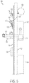
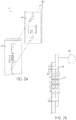
- the vertical lock system 10 includes a padlock disposed in a housing 12 and an actuation knob 14.
- the padlock is placed in a horizontal position with a key insertion surface facing outwardly in an uncovered position. Since the padlock is placed in the horizontal position and the key insertion surface is in the uncovered position, the prior art vertical lock system 10 is vulnerable to drill attack. Further, because the actuating knob 14 of the existing vertical lock system 10 is directly connected to the padlock, a person trying to break-in can apply positive force onto the padlock, using the actuation knob 14, in a locked configuration of the padlock.
- locking mechanisms in accordance with various embodiments of the present invention are disclosed to alleviate the problems and limitations of prior art vertical lock systems.
- the locking mechanism of the present invention is adapted to provide comparatively more secured restricted access to an enclosed property or storage container, such as but not limited to jobsite storage boxes, industrial storage boxes, or household storage boxes, for example.
- the locking mechanism of the present invention is resistant to drill attack.
- the knob of the locking mechanism of the present invention precludes application of positive force on the padlock in a locked configuration of the padlock.
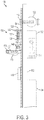
- a locking mechanism 100 is disclosed in accordance with one embodiment of the present invention.
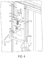
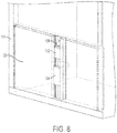
- the locking mechanism 100 is positioned on a center post 102 of a storage container 116, such as the storage container shown in Figures 4 and 8 .
- the center post 102 may be secured to a frame of the storage container.
- the storage container further includes a floor, upright side walls, a rear wall extending upwardly from the floor, and a ceiling attached to the side walls and rear wall.
- the floor, side walls, rear wall, and ceiling of the storage container define a storage cavity.
- the storage container may have more than one storage cavity.
- the locking mechanism comprises a sled 104, an actuator, such as a knob 106, a connecting mechanism 108, a sled arresting mechanism including a cam 110 and a sled arresting element 112, and a padlock 114.
- the locking mechanism 100 is disposed along a closing edge of a hinged door, a sliding door or any other kind of door of a storage container. More specifically, the locking mechanism 100 is preferably disposed at a top portion of the closing edge of the door. However, it should be understood that the present invention is not limited to a particular position of the locking mechanism 100 along the closing edge of the door.
- the sled 104 is adapted to be slidingly disposed on the center post 102.
- the knob 106 is operatively coupled to the center post 102 and the sled 104.
- the knob 106 is operatively connected to the center post 102 by a knob fastener or knob bolt 118 and a bracket 122.
- the knob 106 is adapted to move upward and downward within a slot 120 (shown in Figure 4 ) configured on the center post 102.
- the knob 106 is adapted to actuate the sled 104 when the locking mechanism 100 is in an unlocked configuration.
- the connecting mechanism 108 is coupled to the knob 106 and the sled 104.
- the connecting mechanism 108 is adapted to facilitate reciprocal, or upward and downward, movement of the sled 104 on the center post 102 in an unlocked configuration of the locking mechanism 100.
- the connecting mechanism 108 includes the bracket 122, a fastener 124, and a spring 126.
- the fastener 124 is a bolt.
- the bracket 122 is coupled to the knob 106 by the knob bolt 118.
- the fastener 124 is adapted to connect the bracket 122 to the sled 104.
- the fastener 124 is connected to the bracket 122 by welding.
- the present invention is not limited to any particular joining method used for connecting the fastener 124 to the bracket 122.
- the spring 126 is disposed on the fastener 124. More specifically, as depicted in Figures 3 and 4 , the spring 126 is disposed on the portion of the fastener 124 that is positioned below an upper lip 146 (shown in Figure 4 ) of the sled 104. Additionally, at the bottom end of the fastener 124, a nut and washer assembly 128 is fitted for retaining the spring 126 on the fastener 124 and for preventing removal of the spring 126 from the fastener 124. In the unlocked configuration of the locking mechanism 100 and during an upward motion of the knob 106, the fastener 124 is adapted to move upward to facilitate lifting of the sled 104.
- the bracket 122 and the sled 104 are connected to each other by the fastener 124 so that the sled 104 and the bracket 122 may move or slide with respect to each other.
- the relative sliding movement of the sled 104 with respect to the bracket 122 is facilitated by the spring 126.
- any upward force on the knob 106 is absorbed by the spring 126 without corresponding movement of the sled 104. More particularly, as the knob 106 is moved in the upward direction, the fastener 124, the knob 106, and the bracket 122 pivot, as shown in Figure 5 , thus preventing the bracket 122, sled 104, and padlock 114 from being destroyed.
- the cam 110 is coupled to the sled 104.
- a first end 148 of the cam 110 is connected to a raised lip 130 (shown in Figure 4 ) of the sled 104 in a way such that the cam 110 is adapted to pivot along the first end 148.
- the other end 158 of the cam 110 is connected to the sled arresting element 112.
- the sled arresting element 112 is coupled to the cam 110 and adapted to pivot in accordance with movement of the cam 110 for facilitating locking and unlocking of the sled 104 and the locking mechanism 100.
- the sled arresting element 112 is a horizontal rod.
- the present invention is not limited to any particular example of the sled arresting element 112.
- the padlock 114 is disposed on the center post 102 and adapted to removably lock the sled 104 with respect to the center post 102 by the sled arresting element 112 for facilitating locking and unlocking of the locking mechanism 100.
- the body of the padlock 114 blocks the horizontal movement of the sled arresting element 112.
- the body of the padlock 114 is positioned in front of the sled arresting element 112 and thereby prevents the movement of the sled arresting element 112. Accordingly, the sled 104 cannot move and the latch rod 136 and the doors 138 cannot be opened.
- the padlock 114 may be disposed in a housing or lock box 132 on the outside of the storage container.
- the padlock 114 is preferably positioned so that the key insertion surface of the padlock faces toward the bottom of the storage cabinet or in a downward direction.
- Figures 7a and 7b illustrate an unlocked position of the padlock 114.
- the padlock 114 When the padlock 114 is unlocked, one end of a padlock shackle 115 is removed from a locking/unlocking hole (not shown) on the body of the padlock 114. Accordingly, due to the weight of the body of the padlock 114, the padlock 114 moves downward (due to gravity) and the sled arresting element 112 passes through a shackle loop 113 as the knob 106 is lifted upwards.
- the locking mechanism 100 includes a cover 134 disposed on the center post 102 for precluding a drilling operation. More specifically, the cover 134 is disposed on the center post 102 in such a way that there is limited space between the center post 102 and the padlock 114. Accordingly, this limited space between the center post 102 and the padlock 114, as well as the vertical configuration of the locking mechanism 100 prevents a drill from being positioned to unlock the locking mechanism 100.
- the placement of the cover 134 and the vertical position of the padlock 114 restricts the space and does not allow for a drill to be vertically positioned between the cover 134 and the padlock 114 to drill out all tumblers of the padlock 114 at a straight vertical angle.
- the locking mechanism 100 includes a latch rod 136 disposed on the sled 104.
- the latch rod 136 is adapted to facilitate removable locking of the sled 104 with a door 138 of the storage box 116. More specifically, the latch rod 136 is adapted to be removably secured to door catches 140 of the door 138, as shown in Figure 4 .
- the locking mechanism 100 includes a fixed pivot 142 for preventing locking of the cam 110.
- the cam 110 pivots with respect to the sled 104.
- the pivoting movement of the cam 110 moves the sled arresting element 112 horizontally.
- the sled arresting element 112 may move in an upward direction without pivoting the cam 110, thereby locking the movement of the cam 110 with respect to the sled arresting element 112.
- the fixed pivot 142 prevents the upward movement of the sled arresting element 112.
- the L-shaped bracket 122 may be replaced by a C-shaped channel 144 for providing better control during actuation.
- the padlock 114 In use, to open the storage box 116, the padlock 114 is unlocked. Since the padlock 114 is unlocked (shown in Figures 7a and 7b ), the body of the padlock 114 moves downward (due to gravity) and the sled arresting element 112 passes through the shackle loop 113 as the knob 106 is lifted upwards, or toward the top of the storage cabinet. The upward movement of the knob 106 lifts the fastener 124. As the fastener 124 is raised, due to relative sliding movement of the bracket 122 and sled 104 with respect to center post 102, the spring 126 absorbs the force applied to the knob.
- the force is then transferred to the sled 104 to lift the sled 104 upward, in the same direction as the knob 106. Further, since the cam 110 is connected to the sled 104, the cam 110 pushes the sled arresting element 112 in a horizontal or forward direction through the shackle loop 113 of the padlock shackle 115. At the same time, the latch rod 136 disposed on the sled 104 is lifted and clears the door catches 140. Thus, the doors 138 can be opened.
- the body of padlock 114 blocks the horizontal movement of the sled arresting element 112.
- the body of the padlock 114 is positioned in front of the sled arresting element 112 and thereby prevents the movement of the sled arresting element 112. Accordingly, the sled 104 cannot move and the latch rod 136 and the doors 138 can not be opened.
- blocking of the movement of the sled arresting element 112 prevents movement of the sled 102 and thereby facilitates locking of the locking mechanism 100.
- the knob 106 may be actuated even in the locked configuration of the padlock 114. However, the movement of the knob 106 is absorbed by the spring 126. More particularly, as the knob 106 is moved in the upward direction, the fastener 124 moves upward along with the knob 106 and the bracket 122. The bracket 122 pivots downwardly against the upper lip 146 of the sled 104 as the fastener 124 moves along with the knob 106.
- bracket 122 Due to the pivoting movement of the bracket 122, a first end 123 of the bracket 122 abuts the sled 104, and a second end 125 of the bracket 122 moves away from the sled 104.
- the spring 126 absorbs the force of the bracket 122 pushing on the upper lip 146.
- any upward force applied to the knob 106 is absorbed by the spring 126 and is not transmitted to the bracket 122, sled 104, or padlock 114.
- a locking mechanism 150 is described, in accordance with another embodiment of the present invention.
- the locking mechanism 150 is similar in structure to the locking mechanism 100, except for the addition of a bracket 152, a connecting link 154 and a guide bush 156.
- the bracket 152 is disposed on the center post 102.
- the connecting link 154 hingedly connects the cam 110 to the bracket 152. More specifically, one end of the connecting link 154 is pivotably connected to the bracket 152. Similarly, the other end of the connecting link 154 is pivotably connected to the cam 110. The other end of the connecting link 154 is pivotably connected to the cam 110 at a location in between the pivoting ends of the cam 110.
- the connecting link 154 is adapted to facilitate movement of the sled arresting element 112 by transferring the upward and downward movement of the sled 104 to the pivoting movement of the cam 110. The pivoting movement of the cam 110 is then transferred in to reciprocating motion of the connecting link 154.
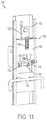
- the guide bush 156 (shown in Figure 11 and 15 ) is adapted to facilitate smooth operation of the locking mechanism 150. More specifically, the guide bush 156 prevents the sled arresting element 112 from falling out of the hole provided on the center post 102 by providing greater surface support.
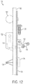
- the locking mechanism 150 is further provided with a cover 134 (shown in Figures 12 to 14b ) in accordance with another embodiment of the present invention.
- the cover 134 has a wedge-shaped structure, as shown in Figures 12 to 14b .
- the cover 134 is disposed on the center post 102 in such a way that there is limited space between the center post 102 and the padlock 114. Accordingly, this limited space between the center post 102 and the padlock 114, as well as the vertical configuration of the locking mechanism 150 prevents a drill from being positioned to unlock the locking mechanism 150.
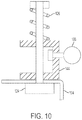
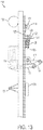
- Figure 13 illustrates the locking mechanism of Figure 11 when the padlock 114 is locked and the knob 106 is actuated.
- the padlock 114 In use, to open the storage box 116, the padlock 114 is unlocked (shown in Figure 14a ). Since the padlock 114 is unlocked, one end of a padlock shackle 115 is removed from a locking/unlocking hole (not shown) on the body of the padlock 114. Accordingly, due to the weight of the body of the padlock 114, the padlock 114 moves downward (due to gravity) and the sled arresting element 112 passes through the shackle loop 113 as the knob 106 is lifted upwards, or toward the top of the storage cabinet. The upward movement of the knob 106 facilitates lifting of the fastener 124.
- the spring 126 absorbs the force applied to the knob. The force is then transferred to the sled 104 to facilitate lifting of the sled 104. Further, since the cam 110 is connected to the sled 104, the cam 110 pushes the sled arresting element 112 through the shackle loop 113 of the padlock shackle 115. At the same time, the latch rod 136 disposed on the sled 104 is lifted and clears the door catches 140. Thus, the doors 138 can be opened.
- the body of padlock 114 blocks the horizontal movement of the sled arresting element 112.
- the body of the padlock 114 is positioned in front of the sled arresting element 112 and thereby prevents the movement of the sled arresting element 112. Accordingly, the sled 104 cannot move and the latch rod 136 and the doors 138 can not be opened.
- blocking of the movement of the sled arresting element 112 prevents movement of the sled 102 and thereby facilitates locking of the locking mechanism 100.
- the knob 106 may be actuated even in the locked configuration of the padlock 114. However, the movement of the knob 106 is absorbed by the spring 126. More particularly, as the knob 106 is moved in the upward direction, the fastener 124 moves upward along with the knob 106 and the bracket 122. The bracket 122 pivots downwardly against the upper lip 146 of the sled 104 as the fastener 124 moves along with the knob 106.
- bracket 122 Due to pivoting movement of the bracket 122, a first end 123 of the bracket 122 abuts to the sled 104 and a second end 125 of the bracket 122 moves away from the sled 104.
- the spring 126 absorbs the force of the bracket 122 pushing on the upper lip 146.
- any upward force applied to the knob 106 is absorbed by the spring 126 and is not transmitted to the bracket 122, sled 104, or padlock 114.
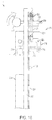
- a locking mechanism 200 is disclosed, in accordance with another embodiment of the present invention.
- the locking mechanism 200 is disposed on a center post 202 of a storage container.
- the locking mechanism 200 includes a sled 204, an actuator or knob 206, a connecting mechanism 208, a sled arresting mechanism including a cam 210 and a sled arresting element 212, and a padlock 214.
- the center post 202, the sled arresting mechanism 212 and the padlock 214 are similar in structure and function to the center post 102, the sled arresting element 112 and the padlock 114 as depicted in Figures 3-4 .
- the sled 204 is slidingly disposed on the center post 202.
- the knob 206 is operatively coupled to the center post 202 and the sled 204.
- One end of the knob 206 is connected to a fixed pivot 216 and the other end of the knob 206 allows a user to move the knob 206 with respect to the fixed pivot 216.
- the knob 206 is adapted to actuate the sled 204 when the locking mechanism 200 is in an unlocked configuration.
- the connecting mechanism 208 is coupled to the knob 206 and the sled 204.
- the connecting mechanism 208 is adapted to facilitate movement of the sled 204 on the center post 202 in an unlocked configuration of the locking mechanism 200.
- the connecting mechanism 208 includes a vertical rod 218, a nut and washer assembly 220 and a spring 222.
- the vertical rod 218 is operatively connected to the sled 204 and the knob 206.
- the vertical rod 218 has a stopper 224 (shown in Figure 17 ) disposed at a lower end thereof. Due to upward movement of the vertical rod 218, the stopper 224 interacts with a receiver 233 of the sled 204, and thereby lifts the sled 204.
- the vertical rod 218 is connected to the knob 206 at a location substantially away from the fixed pivot 216 of the knob.
- the spring 222 is disposed on a top end of the vertical rod 218.
- the nut and washer assembly 220 is disposed on the top end of the vertical rod above the spring 222.
- the spring 222 is positioned between the knob 206 and the nut and the washer assembly 220. More specifically, the spring 222 is disposed between a bracket 226 and the nut and the washer assembly 220. Additionally, as the knob 206 is lifted, the spring 222 absorbs the force applied to the knob 206.
- the spring 222 facilitates movement of the knob 206 without causing corresponding movement of the sled 204 during a locked configuration of the locking mechanism 200.
- the cam 210 is operatively coupled to the connecting mechanism 208 and the sled 204. More specifically, a top end of the cam 210 is connected to a lower end of the vertical rod 218. Further, the middle portion of the cam 210 is connected to a fixed pivot 228 and a lower end of the cam 210 is connected to the sled arresting element 212.
- the cam 210 is adapted to pivot with respect to the fixed pivot 228. More specifically, the lower end of the cam 210 includes a slot 230 for enabling motion of the sled arresting element 212 therein.
- the sled arresting element 212 is coupled to the cam 210 and adapted to move in accordance with movement of the cam 210 for facilitating locking and unlocking of the sled 204 and the locking mechanism 200.
- the cam 210 rotates about fixed pivot 228, the cam 210 pushes the sled arresting element 212 through the shackle loop 213 of the padlock shackle 215.
- the stopper 224 located on the vertical rod 218 interacts with the receiver 233 and lifts the sled 204.
- the latch rod 236 disposed on the sled 204 is lifted and clears the door catches so the doors can be opened.
- the body of the padlock 214 blocks the horizontal movement of the sled arresting element 212.
- the body of the padlock 214 in the locked position of the padlock 214, the body of the padlock 214 is positioned in front of the sled arresting element 212 and thereby prevents the movement of the sled arresting element 212.
- the sled 204 cannot move and the doors 138 cannot be opened.
- blocking of the movement of the sled arresting element 212 prevents movement of the sled 202 and thereby facilitates locking of the locking mechanism 200.
- the knob 206 may still be rotated about the fixed pivot 216.
- Figures 16 to 18 also illustrate a lock box 232 and a latch rod 236.
- the lock box 232 is disposed on the center post 202 and adapted to contain the padlock 214 therein.
- the latch rod 236 facilitates removable locking of the sled 204 with a door of the storage box. More specifically, the latch rod 236 is adapted to be removably secured to door catches of the door of the storage box.
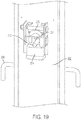
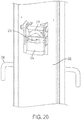
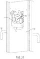
- a locking mechanism 300 is disclosed, in accordance with another embodiment of the present invention.
- the locking mechanism 300 is disposed on a center post 302 of a storage container.
- the locking mechanism 300 is similar in structure and function to the locking mechanism 200, except with respect to actuator or knob 306, connecting mechanism 308 and cam 310.
- the knob 306 is adapted to enable a reciprocating motion, i.e. vertically upward and downward motion, instead of a pivoting motion.
- the connecting mechanism 308 includes a vertical rod 318, a nut and washer assembly 320 and a spring 322.
- the vertical rod 318 is operatively connected to the sled 304 and the knob 306.
- the vertical rod 318 has a stopper (not shown) disposed at a lower end thereof. Due to upward movement of the vertical rod 318, the stopper interacts with a receiver (not shown) of the sled 304 and thereby lifts the sled 304.
- the vertical rod 318 is connected to the knob 306 at a location substantially away from a free end of the knob 306.
- the spring 322 is disposed on the vertical rod 318.
- the nut and washer assembly 320 is disposed on a top end of the vertical rod 318 above the spring 322, wherein the spring 322 is disposed between the knob 306 and the nut and the washer assembly 320.
- the cam 310 is operatively coupled to the connecting mechanism 308 and the sled 304. More specifically, a top end of the cam 310 is connected to a lower end of the vertical rod 318 and a lower end of the cam 310 is connected to the sled arresting element 312. In this embodiment, cam 310 is a straight cam.
- the upward movement of the rod 318 causes the cam 310 to push the sled arresting element 312 through the shackle loop 313 of the padlock shackle 315.
- the stopper (not shown) located on the vertical rod 318 interacts with a receiver of the sled 304 and lifts the sled 304.
- a latch rod 336 disposed on the sled 304 is lifted and clears door catches so the doors can be opened.
- the body of the padlock 314 blocks the horizontal movement of the sled arresting element 312.
- the body of the padlock 314 in the locked position of the padlock 314, the body of the padlock 314 is positioned in front of the sled arresting element 312 and thereby prevents the movement of the sled arresting element 312. Accordingly, the sled 304 cannot move and the doors 138 cannot be opened. Further, blocking of the movement of the sled arresting element 312 prevents movement of the sled 304 and thereby facilitates locking of the locking mechanism 300. However, the knob 306 may still be lifted.
- a spring loaded plate 408 is depicted as the connecting mechanism.
- the spring loaded plate 408 includes a knob plate 410, a sled 412, weld studs 414, flat washers 416, a spring 418, and a knob 420.
- the spring 418 may be installed between the sled 412 and the knob plate 410.
- the weld studs 414 are adapted to be installed in the knob plate 410 and adapted to ride in slots provided in the sled 412 for ensuring alignment.
- the locking mechanisms described above are resistant to drill attack due to vertical configuration of the locking mechanisms and the positioning of a cover on a center post. Further, the locking mechanisms preclude application of positive force on a padlock by an actuation knob in a locked configuration of the padlock, as external force applied on the actuation knob is absorbed by the spring of the locking mechanism and thereby prevents the transmission of such force to the sled and padlock. Still further, the locking mechanisms are easy to use and provide improved security. Additionally, the locking mechanisms provide a user with a quick visual inspection of the locking mechanisms to determine a locked or an unlocked configuration of the locking mechanisms. Due to the vertical configuration of the locking mechanisms, the padlock is not visible to a user in the locked configuration, and the padlock is visible in the unlocked configuration.
Landscapes
- Lock And Its Accessories (AREA)
- Closures For Containers (AREA)
- Packaging Of Annular Or Rod-Shaped Articles, Wearing Apparel, Cassettes, Or The Like (AREA)
- Purses, Travelling Bags, Baskets, Or Suitcases (AREA)
- Switch Cases, Indication, And Locking (AREA)
Claims (13)
- Mécanisme de verrouillage (100) servant à des fins d'utilisation dans un contenant de stockage (116), le contenant de stockage (116) comprenant un montant central (102), le mécanisme de verrouillage (100) ayant une configuration déverrouillée dans laquelle le contenant de stockage (116) peut être ouvert et une configuration verrouillée dans laquelle le contenant de stockage (116) ne peut pas être ouvert, le mécanisme de verrouillage (100) comportant :un coulisseau (104) disposé de manière coulissante sur le montant central (102) ;un actionneur (106) accouplé au montant central (102) et au coulisseau (104), l'actionneur (106) étant adapté pour actionner le coulisseau (104) dans la configuration déverrouillée du mécanisme de verrouillage (100) ;un mécanisme de connexion (108) servant à connecter l'actionneur (106) au coulisseau (104), le mécanisme de connexion (108) comprenant un support (122) accouplé à l'actionneur (106), un organe de fermeture (124) servant à connecter le support (122) au coulisseau (104), et un ressort (126) disposé sur l'organe de fermeture (124) ;une came pivotante (110) accouplée au coulisseau (104) ;un cadenas (114) positionné sur le montant central (102), le cadenas (114) ayant une anse et une surface d'insertion de clé, et le cadenas (114) étant en mesure d'être verrouillé et déverrouillé ;un élément d'arrêt de coulisseau (112) assujetti au niveau de la came pivotante (110), l'élément d'arrêt de coulisseau (112) permettant le mouvement coulissant du coulisseau (104) sur le montant central (102) quand le cadenas (114) est déverrouillé ; etune tige de verrouillage (136) disposée sur le coulisseau (104), la tige de verrouillage (136) étant configurée à des fins de mise en prise avec des loquets de porte (140) sur le contenant de stockage (116) dans la configuration verrouillée du contenant de stockage (116) ;dans lequel, quand le cadenas (114) est verrouillé, l'élément d'arrêt de coulisseau (112) empêche tout mouvement du coulisseau (104), pour ainsi empêcher l'actionneur (106) de déplacer le mécanisme de verrouillage (100) jusque dans la configuration déverrouillée, et quand le cadenas (114) est déverrouillé, l'élément d'arrêt de coulisseau (112) permet le mouvement du coulisseau (104), pour ainsi laisser l'actionneur (106) déplacer le mécanisme de verrouillage (100) jusque dans la configuration déverrouillée.
- Mécanisme de verrouillage (100) selon la revendication 1, dans lequel le cadenas (114) a un corps de cadenas, le corps de cadenas comprenant la surface d'insertion de clé, et la surface d'insertion de clé étant orientée dans une direction allant vers le bas.
- Mécanisme de verrouillage (100) selon la revendication 1, dans lequel le cadenas (114) est positionné à l'intérieur d'un boîtier (132) sur l'extérieur du contenant de stockage (116).
- Mécanisme de verrouillage (100) selon la revendication 1, comportant par ailleurs un couvercle (134) disposé sur le montant central (102) au niveau d'une position sous le cadenas (114) pour empêcher tout accès au cadenas (114).
- Mécanisme de verrouillage (100) selon la revendication 1, dans lequel toute force exercée sur l'actionneur (106) dans la configuration verrouillée est absorbée par le ressort (126).
- Contenant de stockage (116) ayant un montant central (102), un plancher, des parois latérales verticales, une paroi arrière s'étendant vers le haut depuis le plancher, et un plafond attaché aux parois latérales et à la paroi arrière, le plancher, les parois latérales, la paroi arrière, et le plafond définissent une cavité de stockage, le contenant de stockage (116) comprenant par ailleurs le mécanisme de verrouillage (100) selon la revendication 1, le mécanisme de verrouillage (100) comportant par ailleurs un couvercle (134) positionné sur le montant central (102) pour empêcher tout accès au cadenas (114),
dans lequel le cadenas (114) est positionné à l'intérieur du boîtier (132) sur le montant central (102). - Contenant de stockage (116) selon la revendication 6, dans lequel le cadenas (114) a un corps de cadenas, le corps de cadenas comprenant la surface d'insertion de clé, et la surface d'insertion de clé étant orientée dans une direction allant vers le bas.
- Contenant de stockage (116) selon la revendication 6, dans lequel le couvercle (134) est situé sous le cadenas (114) sur le montant central (102).
- Contenant de stockage (116) selon la revendication 6, dans lequel toute force exercée sur l'actionneur (106) dans la configuration verrouillée est absorbée par le ressort (126).
- Contenant de stockage (116) selon la revendication 6, ayant un dispositif de fermeture qui est mobile entre des positions verrouillée et déverrouillée,
dans lequel l'actionneur (106) est en mesure de déplacer le mécanisme de verrouillage (100) d'une position verrouillée dans laquelle tout accès au contenant de stockage (116) est empêché à une position déverrouillée dans laquelle tout accès au contenant est permis et,
dans lequel le mécanisme de connexion (108) comprend un support accouplé à une poignée. - Mécanisme de verrouillage (100) selon la revendication 10, dans lequel toute force exercée sur l'actionneur (106) dans la configuration verrouillée est absorbée par le ressort (126).
- Mécanisme de verrouillage (100) selon la revendication 10, comportant par ailleurs un couvercle (134) disposé sur le montant central (102) au niveau d'une position sous le cadenas (114) pour empêcher tout accès au cadenas (114).
- Mécanisme de verrouillage (100) selon la revendication 10, dans lequel la surface d'insertion de clé du cadenas (114) est orientée dans une direction allant vers le bas.
Applications Claiming Priority (3)
| Application Number | Priority Date | Filing Date | Title |
|---|---|---|---|
| IN1658MU2011 | 2011-06-06 | ||
| US13/205,752 US8601838B2 (en) | 2011-06-06 | 2011-08-09 | Locking mechanism |
| PCT/US2012/037413 WO2012170146A1 (fr) | 2011-06-06 | 2012-05-11 | Mécanisme de verrouillage |
Publications (2)
| Publication Number | Publication Date |
|---|---|
| EP2718523A1 EP2718523A1 (fr) | 2014-04-16 |
| EP2718523B1 true EP2718523B1 (fr) | 2018-02-28 |
Family
ID=47260887
Family Applications (1)
| Application Number | Title | Priority Date | Filing Date |
|---|---|---|---|
| EP12723024.1A Not-in-force EP2718523B1 (fr) | 2011-06-06 | 2012-05-11 | Mécanisme de verrouillage |
Country Status (8)
| Country | Link |
|---|---|
| US (1) | US8601838B2 (fr) |
| EP (1) | EP2718523B1 (fr) |
| CN (1) | CN103608538B (fr) |
| AU (1) | AU2012268747B2 (fr) |
| CA (1) | CA2830421C (fr) |
| ES (1) | ES2663772T3 (fr) |
| MX (1) | MX336643B (fr) |
| WO (1) | WO2012170146A1 (fr) |
Families Citing this family (35)
| Publication number | Priority date | Publication date | Assignee | Title |
|---|---|---|---|---|
| US9187931B2 (en) * | 2011-09-01 | 2015-11-17 | Jamas Enterprises LLC | Sliding pin lock mechanism for overhead door |
| US20140183194A1 (en) * | 2013-01-01 | 2014-07-03 | Steven Richard Ambriz | Closure safety interlock with lockout plate for pressure vessel |
| US8960814B2 (en) | 2013-02-28 | 2015-02-24 | Knaack Llc | Lock system with spring-loaded latching mechanism |
| CN104924654A (zh) * | 2015-05-25 | 2015-09-23 | 江苏通达动力科技股份有限公司 | 一种高速冲分度箱的锁紧装置 |
| US9663278B1 (en) | 2015-12-16 | 2017-05-30 | II Harold C. Daws | Container with improved locking system |
| US10766506B2 (en) * | 2016-07-19 | 2020-09-08 | Trinity Rail Group, Llc | Secure storage box for autorack car |
| WO2018113884A1 (fr) * | 2016-12-23 | 2018-06-28 | Mavako Aps | Système de verrouillage et son utilisation |
| CA178734S (en) | 2017-06-12 | 2019-05-31 | Yeti Coolers Llc | Container |
| USD840150S1 (en) | 2017-06-12 | 2019-02-12 | Yeti Coolers, Llc | Container |
| USD838983S1 (en) | 2017-06-12 | 2019-01-29 | Yeti Coolers, Llc | Container |
| USD872478S1 (en) | 2017-06-12 | 2020-01-14 | Yeti Coolers, Llc | Container |
| USD869160S1 (en) | 2017-06-12 | 2019-12-10 | Yeti Coolers, Llc | Container |
| EP3638598B1 (fr) | 2017-06-12 | 2023-01-18 | Yeti Coolers, LLC | Contenant et système de verrouillage |
| USD872485S1 (en) | 2017-06-12 | 2020-01-14 | Yeti Coolers, Llc | Container |
| USD828028S1 (en) | 2017-06-12 | 2018-09-11 | Yeti Coolers, Llc | Container |
| USD838984S1 (en) | 2017-06-12 | 2019-01-29 | Yeti Coolers, Llc | Container |
| US12108853B2 (en) | 2019-01-06 | 2024-10-08 | Yeti Coolers, Llc | Luggage system |
| US11685573B2 (en) | 2017-06-12 | 2023-06-27 | Yeti Coolers, Llc | Carry strap for container |
| USD873020S1 (en) | 2017-06-12 | 2020-01-21 | Yeti Coolers, Llc | Container |
| USD828029S1 (en) | 2017-06-12 | 2018-09-11 | Yeti Coolers, Llc | Container |
| US11976498B2 (en) | 2017-06-12 | 2024-05-07 | Yeti Coolers, Llc | Container and latching system |
| WO2019137586A1 (fr) * | 2018-01-10 | 2019-07-18 | Mavako Aps | Système de verrouillage et utilisation associée |
| USD904829S1 (en) | 2018-12-11 | 2020-12-15 | Yeti Coolers, Llc | Container accessories |
| USD907445S1 (en) | 2018-12-11 | 2021-01-12 | Yeti Coolers, Llc | Container accessories |
| CN113271806A (zh) | 2019-01-06 | 2021-08-17 | 野醍冷却器有限责任公司 | 行李箱系统 |
| US12225993B2 (en) | 2019-01-06 | 2025-02-18 | Yeti Coolers, Llc | Luggage system |
| USD961926S1 (en) | 2020-06-30 | 2022-08-30 | Yeti Coolers, Llc | Luggage |
| USD954436S1 (en) | 2020-06-30 | 2022-06-14 | Yeti Coolers, Llc | Luggage |
| USD951643S1 (en) | 2020-06-30 | 2022-05-17 | Yeti Coolers, Llc | Luggage |
| USD963344S1 (en) | 2020-06-30 | 2022-09-13 | Yeti Coolers, Llc | Luggage |
| US12325458B2 (en) | 2020-12-09 | 2025-06-10 | Hitachi Rail Sts Usa, Inc. | Independent rail test release mechanism |
| USD960648S1 (en) | 2020-12-16 | 2022-08-16 | Yeti Coolers, Llc | Container accessory |
| USD994438S1 (en) | 2020-12-16 | 2023-08-08 | Yeti Coolers, Llc | Container |
| USD985937S1 (en) | 2020-12-16 | 2023-05-16 | Yeti Coolers, Llc | Container |
| US12110715B2 (en) | 2021-06-17 | 2024-10-08 | Werner Co. | Storage box latch system and security features |
Family Cites Families (17)
| Publication number | Priority date | Publication date | Assignee | Title |
|---|---|---|---|---|
| US2227803A (en) * | 1938-06-25 | 1941-01-07 | Lyon Metal Products Inc | Locker wardrobe |
| US2188703A (en) * | 1939-03-14 | 1940-01-30 | Ethelyn M Burke | Latch and lock mechanism for lockers, etc. |
| US4290281A (en) | 1980-05-27 | 1981-09-22 | Knaack Manufacturing Company | Lock system |
| US4742701A (en) * | 1987-06-18 | 1988-05-10 | Donald Scavetto | Trailer lock |
| CA2427853C (fr) * | 2000-10-31 | 2007-04-17 | Knaack Manufacturing Company | Systeme de verrouillage pour caisse horizontale |
| US6681604B1 (en) | 2000-11-07 | 2004-01-27 | Delta Consolidated Industries | Storage cabinet with locking system having dual release members |
| US7370890B2 (en) | 2000-11-07 | 2008-05-13 | Delta Consolidated Industries | Storage cabinet with locking system having dual release members |
| US6883274B2 (en) * | 2001-11-09 | 2005-04-26 | Knaack Manufacturing Company | Device and method for opening a door |
| US6915670B2 (en) * | 2003-08-29 | 2005-07-12 | Roy E. Gogel | Security device for roll-up doors |
| CN101647670A (zh) * | 2003-09-19 | 2010-02-17 | 韦恩·L·艾斯-柯克 | 对安全装置和涉及安全装置的改进 |
| CN101002001B (zh) | 2004-07-30 | 2011-02-09 | 科奈克制造公司 | 具有闭锁机构的储物柜 |
| US7418846B2 (en) * | 2006-04-14 | 2008-09-02 | Greenlee Textron Inc. | Lock box using puck lock |
| US8342580B2 (en) * | 2006-11-09 | 2013-01-01 | Apex Brands, Inc. | Lock system for a container |
| US20080223091A1 (en) * | 2007-03-16 | 2008-09-18 | Kroening John W | Cabinet-style lock box having a locking mechanism |
| US7823741B2 (en) | 2007-10-04 | 2010-11-02 | Delta Consolidated Industries | Container with locking system |
| US7909419B2 (en) * | 2008-05-07 | 2011-03-22 | Spacesaver Corporation | Restricted access storage compartment |
| US8096152B2 (en) | 2009-02-20 | 2012-01-17 | Knaack Llc | Locking system for a storage container |
-
2011
- 2011-08-09 US US13/205,752 patent/US8601838B2/en active Active
-
2012
- 2012-05-11 EP EP12723024.1A patent/EP2718523B1/fr not_active Not-in-force
- 2012-05-11 AU AU2012268747A patent/AU2012268747B2/en not_active Ceased
- 2012-05-11 ES ES12723024.1T patent/ES2663772T3/es active Active
- 2012-05-11 WO PCT/US2012/037413 patent/WO2012170146A1/fr not_active Ceased
- 2012-05-11 MX MX2013011347A patent/MX336643B/es unknown
- 2012-05-11 CN CN201280027536.1A patent/CN103608538B/zh active Active
- 2012-05-11 CA CA2830421A patent/CA2830421C/fr active Active
Also Published As
| Publication number | Publication date |
|---|---|
| MX2013011347A (es) | 2014-01-08 |
| AU2012268747A1 (en) | 2013-09-26 |
| AU2012268747B2 (en) | 2015-09-03 |
| CA2830421A1 (fr) | 2012-12-13 |
| US8601838B2 (en) | 2013-12-10 |
| EP2718523A1 (fr) | 2014-04-16 |
| US20120305565A1 (en) | 2012-12-06 |
| WO2012170146A1 (fr) | 2012-12-13 |
| ES2663772T3 (es) | 2018-04-17 |
| CA2830421C (fr) | 2015-11-17 |
| MX336643B (es) | 2016-01-26 |
| CN103608538A (zh) | 2014-02-26 |
| CN103608538B (zh) | 2016-06-08 |
Similar Documents
| Publication | Publication Date | Title |
|---|---|---|
| CA2830421C (fr) | Mecanisme de verrouillage | |
| AU2010216274B2 (en) | Locking system for a storage container | |
| US5058258A (en) | Retrofit electric truck door lock | |
| US5470115A (en) | Recessed three-point latching mechanism and method for a storage locker | |
| US20120000255A1 (en) | Lockable enclosure with loading cartridge | |
| NZ525697A (en) | Lock system for a horizontal locking box | |
| USRE44387E1 (en) | Container with locking system | |
| US9890556B2 (en) | Lever action security handle | |
| EP0835358A1 (fr) | Ensemble pene et agencement structural | |
| WO2006094368A1 (fr) | Mecanisme de verrouillage | |
| AU2013379700B2 (en) | Storage container with locking system | |
| JP4082685B2 (ja) | サッシ | |
| AU2019201305B2 (en) | Lock assembly | |
| KR200448881Y1 (ko) | 여닫이문의 방범구조 | |
| KR20100089940A (ko) | 안티패닉 회동방지 조립체 | |
| AU2006222485A1 (en) | Locking mechanism | |
| AU2006201013A1 (en) | Locking mechanism | |
| MXPA98008607A (en) | Accommodation of electrical equipment of multiple doors with interlocking of mecan doors | |
| GB2301393A (en) | Door latching mechanisms |
Legal Events
| Date | Code | Title | Description |
|---|---|---|---|
| PUAI | Public reference made under article 153(3) epc to a published international application that has entered the european phase |
Free format text: ORIGINAL CODE: 0009012 |
|
| 17P | Request for examination filed |
Effective date: 20131113 |
|
| AK | Designated contracting states |
Kind code of ref document: A1 Designated state(s): AL AT BE BG CH CY CZ DE DK EE ES FI FR GB GR HR HU IE IS IT LI LT LU LV MC MK MT NL NO PL PT RO RS SE SI SK SM TR |
|
| DAX | Request for extension of the european patent (deleted) | ||
| 17Q | First examination report despatched |
Effective date: 20170123 |
|
| GRAP | Despatch of communication of intention to grant a patent |
Free format text: ORIGINAL CODE: EPIDOSNIGR1 |
|
| INTG | Intention to grant announced |
Effective date: 20170921 |
|
| GRAS | Grant fee paid |
Free format text: ORIGINAL CODE: EPIDOSNIGR3 |
|
| GRAA | (expected) grant |
Free format text: ORIGINAL CODE: 0009210 |
|
| AK | Designated contracting states |
Kind code of ref document: B1 Designated state(s): AL AT BE BG CH CY CZ DE DK EE ES FI FR GB GR HR HU IE IS IT LI LT LU LV MC MK MT NL NO PL PT RO RS SE SI SK SM TR |
|
| REG | Reference to a national code |
Ref country code: GB Ref legal event code: FG4D Ref country code: CH Ref legal event code: EP |
|
| REG | Reference to a national code |
Ref country code: AT Ref legal event code: REF Ref document number: 974323 Country of ref document: AT Kind code of ref document: T Effective date: 20180315 |
|
| REG | Reference to a national code |
Ref country code: IE Ref legal event code: FG4D |
|
| REG | Reference to a national code |
Ref country code: DE Ref legal event code: R096 Ref document number: 602012043352 Country of ref document: DE |
|
| REG | Reference to a national code |
Ref country code: FR Ref legal event code: PLFP Year of fee payment: 7 |
|
| REG | Reference to a national code |
Ref country code: ES Ref legal event code: FG2A Ref document number: 2663772 Country of ref document: ES Kind code of ref document: T3 Effective date: 20180417 |
|
| REG | Reference to a national code |
Ref country code: NL Ref legal event code: MP Effective date: 20180228 |
|
| REG | Reference to a national code |
Ref country code: LT Ref legal event code: MG4D |
|
| REG | Reference to a national code |
Ref country code: AT Ref legal event code: MK05 Ref document number: 974323 Country of ref document: AT Kind code of ref document: T Effective date: 20180228 |
|
| PG25 | Lapsed in a contracting state [announced via postgrant information from national office to epo] |
Ref country code: LT Free format text: LAPSE BECAUSE OF FAILURE TO SUBMIT A TRANSLATION OF THE DESCRIPTION OR TO PAY THE FEE WITHIN THE PRESCRIBED TIME-LIMIT Effective date: 20180228 Ref country code: HR Free format text: LAPSE BECAUSE OF FAILURE TO SUBMIT A TRANSLATION OF THE DESCRIPTION OR TO PAY THE FEE WITHIN THE PRESCRIBED TIME-LIMIT Effective date: 20180228 Ref country code: NL Free format text: LAPSE BECAUSE OF FAILURE TO SUBMIT A TRANSLATION OF THE DESCRIPTION OR TO PAY THE FEE WITHIN THE PRESCRIBED TIME-LIMIT Effective date: 20180228 Ref country code: NO Free format text: LAPSE BECAUSE OF FAILURE TO SUBMIT A TRANSLATION OF THE DESCRIPTION OR TO PAY THE FEE WITHIN THE PRESCRIBED TIME-LIMIT Effective date: 20180528 Ref country code: CY Free format text: LAPSE BECAUSE OF FAILURE TO SUBMIT A TRANSLATION OF THE DESCRIPTION OR TO PAY THE FEE WITHIN THE PRESCRIBED TIME-LIMIT Effective date: 20180228 Ref country code: FI Free format text: LAPSE BECAUSE OF FAILURE TO SUBMIT A TRANSLATION OF THE DESCRIPTION OR TO PAY THE FEE WITHIN THE PRESCRIBED TIME-LIMIT Effective date: 20180228 |
|
| PG25 | Lapsed in a contracting state [announced via postgrant information from national office to epo] |
Ref country code: SE Free format text: LAPSE BECAUSE OF FAILURE TO SUBMIT A TRANSLATION OF THE DESCRIPTION OR TO PAY THE FEE WITHIN THE PRESCRIBED TIME-LIMIT Effective date: 20180228 Ref country code: LV Free format text: LAPSE BECAUSE OF FAILURE TO SUBMIT A TRANSLATION OF THE DESCRIPTION OR TO PAY THE FEE WITHIN THE PRESCRIBED TIME-LIMIT Effective date: 20180228 Ref country code: GR Free format text: LAPSE BECAUSE OF FAILURE TO SUBMIT A TRANSLATION OF THE DESCRIPTION OR TO PAY THE FEE WITHIN THE PRESCRIBED TIME-LIMIT Effective date: 20180529 Ref country code: BG Free format text: LAPSE BECAUSE OF FAILURE TO SUBMIT A TRANSLATION OF THE DESCRIPTION OR TO PAY THE FEE WITHIN THE PRESCRIBED TIME-LIMIT Effective date: 20180528 Ref country code: RS Free format text: LAPSE BECAUSE OF FAILURE TO SUBMIT A TRANSLATION OF THE DESCRIPTION OR TO PAY THE FEE WITHIN THE PRESCRIBED TIME-LIMIT Effective date: 20180228 Ref country code: AT Free format text: LAPSE BECAUSE OF FAILURE TO SUBMIT A TRANSLATION OF THE DESCRIPTION OR TO PAY THE FEE WITHIN THE PRESCRIBED TIME-LIMIT Effective date: 20180228 |
|
| PG25 | Lapsed in a contracting state [announced via postgrant information from national office to epo] |
Ref country code: AL Free format text: LAPSE BECAUSE OF FAILURE TO SUBMIT A TRANSLATION OF THE DESCRIPTION OR TO PAY THE FEE WITHIN THE PRESCRIBED TIME-LIMIT Effective date: 20180228 Ref country code: PL Free format text: LAPSE BECAUSE OF FAILURE TO SUBMIT A TRANSLATION OF THE DESCRIPTION OR TO PAY THE FEE WITHIN THE PRESCRIBED TIME-LIMIT Effective date: 20180228 Ref country code: EE Free format text: LAPSE BECAUSE OF FAILURE TO SUBMIT A TRANSLATION OF THE DESCRIPTION OR TO PAY THE FEE WITHIN THE PRESCRIBED TIME-LIMIT Effective date: 20180228 Ref country code: RO Free format text: LAPSE BECAUSE OF FAILURE TO SUBMIT A TRANSLATION OF THE DESCRIPTION OR TO PAY THE FEE WITHIN THE PRESCRIBED TIME-LIMIT Effective date: 20180228 |
|
| REG | Reference to a national code |
Ref country code: DE Ref legal event code: R097 Ref document number: 602012043352 Country of ref document: DE |
|
| PG25 | Lapsed in a contracting state [announced via postgrant information from national office to epo] |
Ref country code: CZ Free format text: LAPSE BECAUSE OF FAILURE TO SUBMIT A TRANSLATION OF THE DESCRIPTION OR TO PAY THE FEE WITHIN THE PRESCRIBED TIME-LIMIT Effective date: 20180228 Ref country code: SM Free format text: LAPSE BECAUSE OF FAILURE TO SUBMIT A TRANSLATION OF THE DESCRIPTION OR TO PAY THE FEE WITHIN THE PRESCRIBED TIME-LIMIT Effective date: 20180228 Ref country code: SK Free format text: LAPSE BECAUSE OF FAILURE TO SUBMIT A TRANSLATION OF THE DESCRIPTION OR TO PAY THE FEE WITHIN THE PRESCRIBED TIME-LIMIT Effective date: 20180228 Ref country code: DK Free format text: LAPSE BECAUSE OF FAILURE TO SUBMIT A TRANSLATION OF THE DESCRIPTION OR TO PAY THE FEE WITHIN THE PRESCRIBED TIME-LIMIT Effective date: 20180228 |
|
| REG | Reference to a national code |
Ref country code: CH Ref legal event code: PL |
|
| PLBE | No opposition filed within time limit |
Free format text: ORIGINAL CODE: 0009261 |
|
| STAA | Information on the status of an ep patent application or granted ep patent |
Free format text: STATUS: NO OPPOSITION FILED WITHIN TIME LIMIT |
|
| REG | Reference to a national code |
Ref country code: BE Ref legal event code: MM Effective date: 20180531 |
|
| PG25 | Lapsed in a contracting state [announced via postgrant information from national office to epo] |
Ref country code: MC Free format text: LAPSE BECAUSE OF FAILURE TO SUBMIT A TRANSLATION OF THE DESCRIPTION OR TO PAY THE FEE WITHIN THE PRESCRIBED TIME-LIMIT Effective date: 20180228 |
|
| 26N | No opposition filed |
Effective date: 20181129 |
|
| REG | Reference to a national code |
Ref country code: IE Ref legal event code: MM4A |
|
| PG25 | Lapsed in a contracting state [announced via postgrant information from national office to epo] |
Ref country code: CH Free format text: LAPSE BECAUSE OF NON-PAYMENT OF DUE FEES Effective date: 20180531 Ref country code: LI Free format text: LAPSE BECAUSE OF NON-PAYMENT OF DUE FEES Effective date: 20180531 Ref country code: SI Free format text: LAPSE BECAUSE OF FAILURE TO SUBMIT A TRANSLATION OF THE DESCRIPTION OR TO PAY THE FEE WITHIN THE PRESCRIBED TIME-LIMIT Effective date: 20180228 |
|
| PG25 | Lapsed in a contracting state [announced via postgrant information from national office to epo] |
Ref country code: LU Free format text: LAPSE BECAUSE OF NON-PAYMENT OF DUE FEES Effective date: 20180511 |
|
| PG25 | Lapsed in a contracting state [announced via postgrant information from national office to epo] |
Ref country code: IE Free format text: LAPSE BECAUSE OF NON-PAYMENT OF DUE FEES Effective date: 20180511 |
|
| PG25 | Lapsed in a contracting state [announced via postgrant information from national office to epo] |
Ref country code: BE Free format text: LAPSE BECAUSE OF NON-PAYMENT OF DUE FEES Effective date: 20180531 |
|
| PGFP | Annual fee paid to national office [announced via postgrant information from national office to epo] |
Ref country code: DE Payment date: 20190430 Year of fee payment: 8 Ref country code: ES Payment date: 20190603 Year of fee payment: 8 Ref country code: IT Payment date: 20190527 Year of fee payment: 8 |
|
| REG | Reference to a national code |
Ref country code: GB Ref legal event code: 732E Free format text: REGISTERED BETWEEN 20190704 AND 20190710 |
|
| REG | Reference to a national code |
Ref country code: DE Ref legal event code: R081 Ref document number: 602012043352 Country of ref document: DE Owner name: WERNER CO., GREENVILLE, US Free format text: FORMER OWNER: KNAACK LLC, CRYSTAL LAKE, ILL., US |
|
| PGFP | Annual fee paid to national office [announced via postgrant information from national office to epo] |
Ref country code: FR Payment date: 20190410 Year of fee payment: 8 |
|
| PGFP | Annual fee paid to national office [announced via postgrant information from national office to epo] |
Ref country code: GB Payment date: 20190508 Year of fee payment: 8 |
|
| REG | Reference to a national code |
Ref country code: ES Ref legal event code: PC2A Owner name: WERNER CO. Effective date: 20191205 |
|
| PG25 | Lapsed in a contracting state [announced via postgrant information from national office to epo] |
Ref country code: MT Free format text: LAPSE BECAUSE OF NON-PAYMENT OF DUE FEES Effective date: 20180511 |
|
| PG25 | Lapsed in a contracting state [announced via postgrant information from national office to epo] |
Ref country code: TR Free format text: LAPSE BECAUSE OF FAILURE TO SUBMIT A TRANSLATION OF THE DESCRIPTION OR TO PAY THE FEE WITHIN THE PRESCRIBED TIME-LIMIT Effective date: 20180228 |
|
| PG25 | Lapsed in a contracting state [announced via postgrant information from national office to epo] |
Ref country code: HU Free format text: LAPSE BECAUSE OF FAILURE TO SUBMIT A TRANSLATION OF THE DESCRIPTION OR TO PAY THE FEE WITHIN THE PRESCRIBED TIME-LIMIT; INVALID AB INITIO Effective date: 20120511 Ref country code: PT Free format text: LAPSE BECAUSE OF FAILURE TO SUBMIT A TRANSLATION OF THE DESCRIPTION OR TO PAY THE FEE WITHIN THE PRESCRIBED TIME-LIMIT Effective date: 20180228 |
|
| PG25 | Lapsed in a contracting state [announced via postgrant information from national office to epo] |
Ref country code: MK Free format text: LAPSE BECAUSE OF NON-PAYMENT OF DUE FEES Effective date: 20180228 |
|
| PG25 | Lapsed in a contracting state [announced via postgrant information from national office to epo] |
Ref country code: IS Free format text: LAPSE BECAUSE OF FAILURE TO SUBMIT A TRANSLATION OF THE DESCRIPTION OR TO PAY THE FEE WITHIN THE PRESCRIBED TIME-LIMIT Effective date: 20180628 |
|
| REG | Reference to a national code |
Ref country code: DE Ref legal event code: R119 Ref document number: 602012043352 Country of ref document: DE |
|
| GBPC | Gb: european patent ceased through non-payment of renewal fee |
Effective date: 20200511 |
|
| PG25 | Lapsed in a contracting state [announced via postgrant information from national office to epo] |
Ref country code: FR Free format text: LAPSE BECAUSE OF NON-PAYMENT OF DUE FEES Effective date: 20200531 Ref country code: GB Free format text: LAPSE BECAUSE OF NON-PAYMENT OF DUE FEES Effective date: 20200511 |
|
| PG25 | Lapsed in a contracting state [announced via postgrant information from national office to epo] |
Ref country code: DE Free format text: LAPSE BECAUSE OF NON-PAYMENT OF DUE FEES Effective date: 20201201 |
|
| REG | Reference to a national code |
Ref country code: ES Ref legal event code: FD2A Effective date: 20210929 |
|
| PG25 | Lapsed in a contracting state [announced via postgrant information from national office to epo] |
Ref country code: IT Free format text: LAPSE BECAUSE OF NON-PAYMENT OF DUE FEES Effective date: 20200511 |
|
| PG25 | Lapsed in a contracting state [announced via postgrant information from national office to epo] |
Ref country code: ES Free format text: LAPSE BECAUSE OF NON-PAYMENT OF DUE FEES Effective date: 20200512 |