EP2719012B1 - Vorrichtung zur überwachung des spannungsausgangs der zellen eines elektrochemischen generators - Google Patents
Vorrichtung zur überwachung des spannungsausgangs der zellen eines elektrochemischen generators Download PDFInfo
- Publication number
- EP2719012B1 EP2719012B1 EP12721565.5A EP12721565A EP2719012B1 EP 2719012 B1 EP2719012 B1 EP 2719012B1 EP 12721565 A EP12721565 A EP 12721565A EP 2719012 B1 EP2719012 B1 EP 2719012B1
- Authority
- EP
- European Patent Office
- Prior art keywords
- resonant
- electrochemical generator
- nominal
- resonant circuits
- cells
- Prior art date
- Legal status (The legal status is an assumption and is not a legal conclusion. Google has not performed a legal analysis and makes no representation as to the accuracy of the status listed.)
- Active
Links
Images

Classifications
-
- G—PHYSICS
- G01—MEASURING; TESTING
- G01R—MEASURING ELECTRIC VARIABLES; MEASURING MAGNETIC VARIABLES
- G01R19/00—Arrangements for measuring currents or voltages or for indicating presence or sign thereof
- G01R19/165—Indicating that current or voltage is either above or below a predetermined value or within or outside a predetermined range of values
- G01R19/16533—Indicating that current or voltage is either above or below a predetermined value or within or outside a predetermined range of values characterised by the application
- G01R19/16538—Indicating that current or voltage is either above or below a predetermined value or within or outside a predetermined range of values characterised by the application in AC or DC supplies
- G01R19/16542—Indicating that current or voltage is either above or below a predetermined value or within or outside a predetermined range of values characterised by the application in AC or DC supplies for batteries
-
- G—PHYSICS
- G01—MEASURING; TESTING
- G01R—MEASURING ELECTRIC VARIABLES; MEASURING MAGNETIC VARIABLES
- G01R31/00—Arrangements for testing electric properties; Arrangements for locating electric faults; Arrangements for electrical testing characterised by what is being tested not provided for elsewhere
- G01R31/36—Arrangements for testing, measuring or monitoring the electrical condition of accumulators or electric batteries, e.g. capacity or state of charge [SoC]
- G01R31/382—Arrangements for monitoring battery or accumulator variables, e.g. SoC
-
- G—PHYSICS
- G01—MEASURING; TESTING
- G01R—MEASURING ELECTRIC VARIABLES; MEASURING MAGNETIC VARIABLES
- G01R31/00—Arrangements for testing electric properties; Arrangements for locating electric faults; Arrangements for electrical testing characterised by what is being tested not provided for elsewhere
- G01R31/36—Arrangements for testing, measuring or monitoring the electrical condition of accumulators or electric batteries, e.g. capacity or state of charge [SoC]
- G01R31/392—Determining battery ageing or deterioration, e.g. state of health
-
- G—PHYSICS
- G01—MEASURING; TESTING
- G01R—MEASURING ELECTRIC VARIABLES; MEASURING MAGNETIC VARIABLES
- G01R31/00—Arrangements for testing electric properties; Arrangements for locating electric faults; Arrangements for electrical testing characterised by what is being tested not provided for elsewhere
- G01R31/36—Arrangements for testing, measuring or monitoring the electrical condition of accumulators or electric batteries, e.g. capacity or state of charge [SoC]
- G01R31/396—Acquisition or processing of data for testing or for monitoring individual cells or groups of cells within a battery
-
- H—ELECTRICITY
- H01—ELECTRIC ELEMENTS
- H01M—PROCESSES OR MEANS, e.g. BATTERIES, FOR THE DIRECT CONVERSION OF CHEMICAL ENERGY INTO ELECTRICAL ENERGY
- H01M10/00—Secondary cells; Manufacture thereof
- H01M10/42—Methods or arrangements for servicing or maintenance of secondary cells or secondary half-cells
- H01M10/48—Accumulators combined with arrangements for measuring, testing or indicating the condition of cells, e.g. the level or density of the electrolyte
- H01M10/482—Accumulators combined with arrangements for measuring, testing or indicating the condition of cells, e.g. the level or density of the electrolyte for several batteries or cells simultaneously or sequentially
-
- H—ELECTRICITY
- H01—ELECTRIC ELEMENTS
- H01M—PROCESSES OR MEANS, e.g. BATTERIES, FOR THE DIRECT CONVERSION OF CHEMICAL ENERGY INTO ELECTRICAL ENERGY
- H01M10/00—Secondary cells; Manufacture thereof
- H01M10/42—Methods or arrangements for servicing or maintenance of secondary cells or secondary half-cells
- H01M10/48—Accumulators combined with arrangements for measuring, testing or indicating the condition of cells, e.g. the level or density of the electrolyte
- H01M10/486—Accumulators combined with arrangements for measuring, testing or indicating the condition of cells, e.g. the level or density of the electrolyte for measuring temperature
-
- H—ELECTRICITY
- H01—ELECTRIC ELEMENTS
- H01M—PROCESSES OR MEANS, e.g. BATTERIES, FOR THE DIRECT CONVERSION OF CHEMICAL ENERGY INTO ELECTRICAL ENERGY
- H01M8/00—Fuel cells; Manufacture thereof
- H01M8/04—Auxiliary arrangements, e.g. for control of pressure or for circulation of fluids
- H01M8/04298—Processes for controlling fuel cells or fuel cell systems
- H01M8/04313—Processes for controlling fuel cells or fuel cell systems characterised by the detection or assessment of variables; characterised by the detection or assessment of failure or abnormal function
- H01M8/0432—Temperature; Ambient temperature
-
- H—ELECTRICITY
- H01—ELECTRIC ELEMENTS
- H01M—PROCESSES OR MEANS, e.g. BATTERIES, FOR THE DIRECT CONVERSION OF CHEMICAL ENERGY INTO ELECTRICAL ENERGY
- H01M8/00—Fuel cells; Manufacture thereof
- H01M8/04—Auxiliary arrangements, e.g. for control of pressure or for circulation of fluids
- H01M8/04298—Processes for controlling fuel cells or fuel cell systems
- H01M8/04313—Processes for controlling fuel cells or fuel cell systems characterised by the detection or assessment of variables; characterised by the detection or assessment of failure or abnormal function
- H01M8/04537—Electric variables
- H01M8/04544—Voltage
- H01M8/04552—Voltage of the individual fuel cell
-
- H—ELECTRICITY
- H01—ELECTRIC ELEMENTS
- H01M—PROCESSES OR MEANS, e.g. BATTERIES, FOR THE DIRECT CONVERSION OF CHEMICAL ENERGY INTO ELECTRICAL ENERGY
- H01M8/00—Fuel cells; Manufacture thereof
- H01M8/04—Auxiliary arrangements, e.g. for control of pressure or for circulation of fluids
- H01M8/04298—Processes for controlling fuel cells or fuel cell systems
- H01M8/04694—Processes for controlling fuel cells or fuel cell systems characterised by variables to be controlled
- H01M8/04858—Electric variables
- H01M8/04865—Voltage
- H01M8/04873—Voltage of the individual fuel cell
-
- Y—GENERAL TAGGING OF NEW TECHNOLOGICAL DEVELOPMENTS; GENERAL TAGGING OF CROSS-SECTIONAL TECHNOLOGIES SPANNING OVER SEVERAL SECTIONS OF THE IPC; TECHNICAL SUBJECTS COVERED BY FORMER USPC CROSS-REFERENCE ART COLLECTIONS [XRACs] AND DIGESTS
- Y02—TECHNOLOGIES OR APPLICATIONS FOR MITIGATION OR ADAPTATION AGAINST CLIMATE CHANGE
- Y02E—REDUCTION OF GREENHOUSE GAS [GHG] EMISSIONS, RELATED TO ENERGY GENERATION, TRANSMISSION OR DISTRIBUTION
- Y02E60/00—Enabling technologies; Technologies with a potential or indirect contribution to GHG emissions mitigation
- Y02E60/10—Energy storage using batteries
-
- Y—GENERAL TAGGING OF NEW TECHNOLOGICAL DEVELOPMENTS; GENERAL TAGGING OF CROSS-SECTIONAL TECHNOLOGIES SPANNING OVER SEVERAL SECTIONS OF THE IPC; TECHNICAL SUBJECTS COVERED BY FORMER USPC CROSS-REFERENCE ART COLLECTIONS [XRACs] AND DIGESTS
- Y02—TECHNOLOGIES OR APPLICATIONS FOR MITIGATION OR ADAPTATION AGAINST CLIMATE CHANGE
- Y02E—REDUCTION OF GREENHOUSE GAS [GHG] EMISSIONS, RELATED TO ENERGY GENERATION, TRANSMISSION OR DISTRIBUTION
- Y02E60/00—Enabling technologies; Technologies with a potential or indirect contribution to GHG emissions mitigation
- Y02E60/30—Hydrogen technology
- Y02E60/50—Fuel cells
Definitions
- the invention relates to a monitoring of the voltage delivered by the elementary cells of electrochemical generators, to control their operating state.
- Electrochemical generators usually consist of a stack of multiple cells in series. Indeed, an elementary cell does not provide an output voltage of a sufficient level to be exploitable as a power source in an industrial or consumer electrical appliance: a fuel cell cell is capable of providing a voltage included between 0.4 volts and 1.2 volts, depending on the nature of the battery, and in particular depending on the fuel and the oxidant used, and the electric current delivered, which depends mainly on the load; a battery cell, is capable of supplying a voltage of between 1.2 volts and 3.8 volts, depending on the state of charge of the cell, the temperature, and the electric current delivered.
- the stack of cells in series makes it possible, by an additive effect, to obtain a usable output voltage for using these generators as an energy source in electrical systems, for various applications in the consumer or industrial field.
- This can range from the power supply system for recharging portable devices (telephone, computer), to the power supply system for on-board power systems, for example for electric vehicle traction.
- We can also mention as industrial application of these generators, energy storage stations (electric or gas).
- Monitoring and analyzing the evolution of the cell output voltages assumes means for measuring the voltage at the terminals of each cell, and means for shaping and signal processing allowing the analysis of the measures, to obtain information on their proper functioning.
- FR 2 427 817 A1 discloses a device for monitoring the electromotive force of an electric battery which comprises a resonance circuit, formed by a varicap diode and an inductor, the circuit being coupled to an oscillator.
- JP 6 233474 A discloses a method of detecting the voltage of a battery using a varicap diode D1 which forms a resonance circuit with a surface acoustic wave device.
- JP 2004 157077 A discloses using a varicap diode 2 in combination with a variable frequency generator 3 to determine the voltage of an individual cell of a stack of cells electrically connected in series.
- Suitable galvanic isolation must then be provided, which can be very restrictive for certain voltage measurement techniques.
- An object of the invention is to propose an alternative solution for monitoring the state of cells of an electrochemical generator, which is both inexpensive, simple to implement, even in embedded power systems, and reliable in time.
- the idea underlying the invention is based on the use of a resonant circuit comprising a reactive passive component biased by the voltage delivered by a cell, and whose impedance varies as a function of the DC voltage across its terminals.
- a variation of the voltage delivered by a cell then results in a variation of the resonance frequency of the associated resonance circuit.
- This transposition in the frequency domain makes it possible to simplify the connection and considerably reduces all the risks of associated malfunction. It also simplifies the realization of galvanic isolation, for embedded power systems.
- Another advantage is that the measurement is passive because it requires very little current, which contributes to the reliability, compactness and robustness of the proposed monitoring system.
- the resonant circuits are connected in series, and the first reactive passive component of a resonant circuit is biased by the voltage delivered by a cell.
- the first reactive component is advantageously a varicap diode and the second reactive passive component is either an inductor or a resonant circuit such as a quartz for example.
- the resonant circuits corresponding to different cells have different nominal resonance frequencies.
- the detection means then detects different resonance peaks, corresponding to the different cells. From the detection of the positions of the resonance peaks on a signal raised across the set of resonant circuits, it is thus possible to obtain information on the state of each of the cells of the stack.
- the resonant circuits are powered by the generator via a wired connection.
- the resonant circuits are powered by the generator via an isolation transformer.
- the measurement / detection of the voltage signal uses radio frequency means.
- the excitation of the resonant circuits and the measurement / detection of the voltage signal use radiofrequency means.
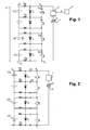
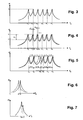
- a first embodiment of a control circuit according to the invention is illustrated on the figure 1 applied to a stack of N cells UC i of an electrochemical generator.
- Each cell UC i delivers at its terminals an elementary DC voltage Ui.
- a voltage U is obtained equal to the sum of N elementary DC voltages U i.
- the control circuit comprises a resonant circuit per cell UC i .
- the resonant circuit comprises a first reactive passive component D i and a second reactive passive component L i connected to the terminals of each cell UC i . All the resonant circuits are placed in series.
- the first reactive passive component is preferably a varicap diode and the second reactive passive component is an inductor. They are each connected in parallel on the cell UC i , as illustrated, forming a parallel LC type resonant circuit, with the capacitance C i of the varicap diode and the inductance L i .
- the value of the capacitance C i of the diode reflects the level of the voltage U i delivered by the cell UC i .
- the measurement of the resonance frequency of the resonant circuit (L i , D i ) is an indirect measurement of the voltage delivered by the cell UC i .
- This indirect measurement is obtained by using excitation / detection means of the resonant circuits comprising a generator 1 of a variable frequency signal f g for supplying all of the resonant circuits and a means 2 for detecting the position of peaks of resonance: when the frequency f g of the signal delivered by the generator corresponds to the resonance frequency fd i of a resonant circuit (D i , L i ), the curve
- g (f g ) ( figure 3 ) will reveal a resonance peak corresponding to the oscillation of the resonant circuit concerned.
- This excitation / detection circuit is represented in a very symbolic manner in the figures by a rectangle representing a detection circuit 2 in series with a circle representing the generator of a variable frequency excitation signal, the assembly being placed in position. parallel to the terminals E 1 and E 2 of all the resonant circuits.
- each of the resonant circuits there is provided for each of the resonant circuits at least one decoupling capacitor Cd placed in series with the inductance L i , this series set itself placed in parallel on the varicap Di diode.
- decoupling capacitors make it possible to isolate the inductances L i from the DC voltage delivered by the cells.
- the resonant circuits share, in pairs, a decoupling capacitor Cd.
- This arrangement makes it possible, with N + 1 decoupling capacitances Cd, to place two decoupling capacitors Cd by resonant circuit, connected on each side of the corresponding cell UC i .
- Each varicap diode can be polarized directly by the voltage delivered by the associated cell UC i , or, as shown in FIGS. Figures 1 and 2 by means of resistors Rp.
- a resistor Rp is placed in series between each terminal of the cell UC i and the associated varicap diode. For N cells, this is done with N + 1 resistors Rp, the cells sharing two by two the same decoupling resistance.
- This resistor Rp enables the decoupling of the bias circuit of the varicap diode D i , comprising the cell UC i and the varicap diode D i , of the resonant circuit formed by the varicap diode D i and the inductance L i , in the small circuit. alternative signals.
- This resistance has in practice a high value, of the order of 10 6 ohms, which does not disturb the bias circuit, the reverse bias current of the diode being almost zero.
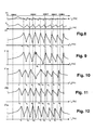
- the principle of detection is illustrated on the Figures 3 to 5 .
- the characteristics of the varicap diodes and the inductances of each of the resonant circuits are chosen to obtain the different desired nominal resonant frequencies for a nominal voltage across each of the cells, with a coefficient of quality the best possible, which makes favorable the precise detection of the position of the resonance peaks.
- the detection circuit 2 makes it possible to determine the level of the module
- This impedance determination is done in a conventional manner, by a measurement of voltage and / or current at the terminals E 1 and E 2 , and according to the electrical characteristics of the excitation signal emitted by the generator 1 used, without it being be useful to detail it.
- the variation curve of this impedance with the frequency f g of the generator 1 comprises N offset resonance peaks.
- each resonance peak corresponds to an impedance maxima obtained at a frequency f g equal to the corresponding resonance nominal frequency.
- g (f g ) at the terminals of the set of resonant circuits thus has the shape represented on the figure 3 .
- each detected resonance peak corresponds to a specific resonant circuit and therefore to a determined cell.
- the position of a resonance peak thus gives the resonance frequency fd i of the corresponding resonance circuit.
- the invention makes it possible to directly exploit the resonance frequency measurements, to obtain information on the state of the cells, without it being necessary to go back to the voltage delivered by each cell.
- the absolute information given by the position of each detected resonance peak is used to obtain an indication of the state of a corresponding cell. It thus consists in determining for each peak of resonance, the difference with its nominal position.
- This measurement is illustrated on the figure 4 , on which are represented in full line, a raised curve, and dashed, the nominal curve.
- the nominal resonance frequency fn 2 the nominal value of the impedance across the resonant circuits, at this nominal resonance frequency fn 2 , is z2. It is compared with the value z'2 of the impedance at the same resonant frequency fn2, on the raised curve.
- the impedance difference ⁇ z 2 reflects a variation of the resonance peak position of the corresponding resonant circuit.
- These frequency or impedance deviations can advantageously provide indications of exceeding the threshold, by comparing these deviations, with predetermined thresholds. We can thus determine if a cell is altered, but still viable, or permanently degraded.
- a sensor 4 providing a measurement of the voltage U across the N cells of the stack and / or another sensor 3 locally measuring the temperature ⁇ in the generator.
- the figure 5 thus shows an anomaly of the spacings between the 2 nd peak and the 3 rd peak, between the 3 th peak and the 4 th peak, and between the 4 th peak and the 5 th peak, reflecting a heterogeneous evolution of the cells.
- FIG. 6 and 7 illustrate a variant implementation of the control circuit according to the invention, simpler implementation, the resonant circuits being made with identical components, so as to be centered on the same nominal resonant frequency fn.
- the impedance variation curve with the signal frequency of the generator 1 then has the shape of the solid line curve illustrated on FIG. figure 6 , centered on the nominal resonance frequency fn.
- the state of the cells can evolve homogeneously: a curve centered on a different resonance frequency fd, as shown by the dotted curve on the figure 6 but of identical overall appearance.
- the impedance curve will deform and show at least one secondary impedance peak centered on a "secondary" resonant frequency fds, in more than one central peak centered on a main resonance frequency fd.
- the detection of secondary peak (s) is an indication of a heterogeneous evolution of the cells of the stack. The detection of the deformation will be all the easier as the resonant circuits will have a high coefficient of quality.
- This implementation is simpler to implement since it uses resonant circuits all identical. It can be used when one only seeks to monitor the overall evolution of cells. It may advantageously be coupled to a measurement of the voltage at the terminals G 1 , G 2 of the N cells of the stack and / or the average temperature in the generator.
- PEMFC proton exchange membrane fuel cells or polymer membrane electrolyte
- the control circuit must be defined in correspondence with the electrical characteristics of these cells, whose terminal voltage may vary by 0.4 volts, which is the low limit voltage below which there is a risk of overheating or destruction. of a cell, and 1 volt, which is the empty voltage of the cell.
- the varicap reference diode manufacturer BB202 which is a CMS component of widely used consumer electronics, is well suited for monitoring this voltage range. Indeed its capacity varies very significantly, from 30 picofarads to about 15 picofarads, with the reverse bias voltage when it goes from 0.3 volts to 1.5 volts, allowing a precision detection in this range of operation. It is thus possible to use this varicap diode in each of the resonant circuits.
- control circuit is chosen using resonant circuits centered on different resonance frequencies. It is therefore necessary to vary the value of the impedance L i from one resonant circuit to the other.
- ATC 1008 WL manufacturer's reference inductors of 100 nH, 150 nH, 220 nH, 330 nH, 470 nH, 680 nH, 1000 nH, were chosen. and 1500 nanoHenrys for producing the reactive elements L 1 , L 2 , L 3 , L 4 , L 5 , L 6 , L 7 , L 8 of the eight resonant circuits.
- the inductive components proposed have satisfactory quality factors, typically 60 for L 1 and 28 for L 8 .
- the values of the decoupling resistances Rp, the decoupling capacitors Cd, the wiring impedances and the quality coefficient of each of the inductive elements have been taken into account in the form of an appropriate value resistor in parallel on each resonant circuit.
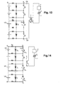
- g (f) illustrated on the figure 8 (Frequency axis in logarithmic scale) is the nominal curve, obtained for cells each delivering a nominal voltage of 1 volt, applied as the reverse bias voltage of the varicap diode of each of the eight resonant circuits. It is in practice obtained by the measurement by the detection circuit 2 of the voltage and the current across the set of resonant circuits, as a function of the frequency of the excitation signal emitted by the frequency generator 1.
- the curves 9 to 12 are the impedance variation curves with the frequency of excitation of the frequency generator 1, reflecting the situation of the generator in different cases. They highlight either a homogeneous behavior of the cells, or heterogeneous behaviors revealing defects on one or more cells, or a general failure of all the cells.
- the position of the detected resonance peaks give as resonance frequencies fd 1 to fd 8 , respectively 28.93 MHz, 35.51 MHz, 43.05 MHz, 44.7 MHz, 61.94 MHz, 75.92 MHz, 92.05 MHz, 112.46 MHz: thus all detected resonant frequencies are equal or very close to their nominal value, except fd 4 which is well apart, of 7.18 MHz.
- this frequency fd 4 corresponds to a voltage of 0.4 volts delivered by the corresponding cell.
- a threshold of 7 MHz for this cell it is possible to detect a threshold overshoot corresponding to the low limit voltage of the cell, by using the difference between the detected resonance frequency fd 4 and the nominal frequency fn 4 .
- the curve of the figure 10 shows another situation in which only the 4 th cell corresponds to a nominal operating state with a detected resonance frequency fd 4 equal to its frequency of nominal resonant fn 4, while for the other cells, the positions of the detected resonance peaks give resonant frequencies that are quite different from their nominal values, which correspond to simulation conditions in which these cells each supply a voltage of 0.4 volts.
- 24.87 MHz for fd 1 30.53 MHz for fd 2 , 37.04 MHz for fd 3 , 53.33 MHz, for fd 5 , 65.26 MHz for fd 6 , 79.07 MHz for fd 7 and 96.6 MHz for fd 8 .
- the figure 11 corresponds to a simulation with all the defective cells, delivering at their terminals only a voltage of 0.4 volts: the curve obtained is globally homogeneous but shifted in frequency with respect to the figure 8 .
- the state of each of the cells by considering the resonant frequency of each detected peak, and / or the homogeneous or non-homogeneous behavior of the cells, by considering the spacing between the detected peaks.
- figure 12 illustrates an intermediate situation of the figure 11 cells each delivering a homogeneous voltage of 0.7 volts.
- the curve shows a homogeneous evolution, but with lesser frequency differences, the detected resonant frequencies fd 1 to fd 8 being respectively 26.87 MHz, 33.01 MHz, 40.06 MHz, 48.19 MHz, 57.54 MHz , 70.52 MHz, 85.51 MHz, 104.47 MHz.
- the various measurements made according to the invention from the positions of the detected resonance peaks would show that each cell is less good, and / or that each cell is less good but not completely defective (no crossing of threshold), and / or a homogeneous behavior of the cells.
- the proposed invention can easily include galvanic isolation.
- a transformer T is provided, a secondary winding B2 supplies the resonant circuits (L i , D i ).
- the secondary winding is connected to the terminals E1, E2 of the set of resonant circuits, via decoupling capacitors Cd ', which are necessary in the illustrated configuration in which decoupling capacitors Cd are directly connected to each other. series with each inductive element.
- the primary winding B1 is connected to the terminals of the series assembly of the generator 1 and the measuring circuit 2.
- the elements placed in parallel with the elements "varicap” are inductances.
- the use of resonant circuits replacing these inductances could be advantageously envisaged, these resonant circuits being able to give the total resonant circuit a higher coefficient of quality.
- elements such as quartz instead of inductors L i could be considered.
- Partially wired versions can be envisaged: wired connection for the polarization of the resonant circuits by the cells, connection contactless for excitation and / or frequency detection.
- the Figures 14 to 16 are symbolic illustrations.
- the secondary winding of the transformer T is carried out by elementary windings B 2i , produced by the inductive antennas L i of the resonant circuits.
- the detection means comprises an inductive antenna array (producing a transformer T) for collecting an alternating signal originating from the reactive components of the resonant circuits, which is the signature in alternative mode of the resonant circuits, the resonant circuits being fed by the frequency generator by a wired connection, that is to say that the frequency generator 1 is connected to the terminals E 1 and E 2 of the set of resonant circuits by wires .
- This variant would improve the quality of the measurements made, while remaining in a contactless transmission of the elementary voltages information.
- the Figures 15 and 16 illustrate another partially wired version, using radiofrequency electric antennas.
- the resonant circuits each comprise a radiofrequency electric antenna A i excited by an electric antenna A '.
- the frequency f g corresponds to the resonant frequency of a resonant circuit associated with a cell
- the equivalent impedance seen by the antenna A ' sees an extremum.
- This variant can use the antenna of the detection circuit as symbolized on the Figures 15 and 16 , or another antenna.
- each transmitting radio antenna is placed in series with the inductance L i of the associated resonant circuit and advantageously also provides the decoupling capacitance function Cd making it possible to deal with the DC voltage component which would otherwise be seen by the single parasitic resistor of the inductance L i .
- the transmitting radio antenna is placed in parallel with the inductor L i .
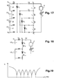
- the figure 17 illustrates another alternative embodiment of the resonant circuits, according to a nested structure.
- the varicap diode D n of rank n is polarized directly, or through resistors Rp as illustrated, by the voltage across the n cells of rank 1 to n.
- the resonant circuit of rank n associated with the varicap diode D n comprises the series set of n inductances L 1 to L n , in parallel on the varicap diode D n , each inductance being in series on one of the n cells.
- the diode D n is thus biased by the voltage delivered across the n cells, and the resonant circuit of associated rank n can monitor the voltage U1 + U2 + .... One, across the n cells of rank 1 to n. Since the varicap diodes are biased by all different voltages, each one will have to be chosen to correspond to a different voltage range to be monitored.
- the structure makes it possible to use N inductances of the same value.
- FIG 17 illustrates a fully wired implementation as well as the presence of serial decoupling capabilities, shared by adjacent resonance circuits. All variants described, including decoupling capacitors or partially wired versions can be applied to a nested structure of the resonant circuits. Finally, the nested structure can nest varicap diodes as illustrated. It can also embed inductances, even varicap diodes and inductors.
- FIGS. 18 and 19 illustrate another implementation of the invention, using LC series resonant circuits, rather than parallel.
- the resonance peaks will then correspond to impedance minima as illustrated on the figure 19 .
- g (f g ) remain the same as those exposed in the case of resonant circuits of parallel LC type.
- the invention which has just been described thus proposes a monitoring device comprising a fully passive local circuit, associated with each cell of a stack, and all these circuits are excited by a single external source, a variable frequency generator. to perform cell voltage measurements by continuous frequency sweep. It allows integration within the electrochemical generator and provides a considerable advantage in terms of connectivity since only two measurement wires are required by electrochemical generator stack in a wired configuration, and also allows a contactless implementation.
Landscapes
- Engineering & Computer Science (AREA)
- Manufacturing & Machinery (AREA)
- Chemical & Material Sciences (AREA)
- Chemical Kinetics & Catalysis (AREA)
- Electrochemistry (AREA)
- General Chemical & Material Sciences (AREA)
- General Physics & Mathematics (AREA)
- Physics & Mathematics (AREA)
- Life Sciences & Earth Sciences (AREA)
- Sustainable Development (AREA)
- Sustainable Energy (AREA)
- Power Engineering (AREA)
- Investigating Or Analyzing Materials By The Use Of Electric Means (AREA)
- Secondary Cells (AREA)
- Charge And Discharge Circuits For Batteries Or The Like (AREA)
- Measurement Of Current Or Voltage (AREA)
Claims (19)
- Elektrochemischer Generator, der wenigstens einen Stapel von N Zellen (UCi) umfasst, die elektrisch in Serie geschaltet und mit Mitteln zum Regeln der Spannung an den Anschlüssen der Zellen ausgestattet sind, dadurch gekennzeichnet, dass die Steuermittel Folgendes umfassen:- für jede zu steuernde Zelle (UCi):- eine erste reaktive passive Komponente (Di), deren Impedanz in Abhängigkeit von der Gleichspannung an ihren Anschlüssen variiert, wobei die Komponente durch die Spannung polarisiert wird, die von der zu steuernden Zelle (UCi) oder von einer Gruppe von in Serie geschalteten Zellen zugeführt wird, die die zu steuernde Zelle beinhaltet; und- wenigstens eine zweite reaktive passive Komponente (Li), die mit der ersten reaktiven passiven Komponente eine serielle oder parallele Resonanzschaltung mit einer vorbestimmten Nennresonanzfrequenz (fni) für eine von der Zelle oder der Gruppe von Zellen angelegten Nennvorspannung bildet;- einen Generator (1) für ein Signal mit veränderlicher Frequenz (fg), der den Satz von N Resonanzschaltungen speist;- ein Mittel (2) zum Erkennen der Position der/von Resonanzspitze(n) des so gespeisten Satzes, wobei dieses Mittel eine Anzeige einer Abweichung zwischen einer Resonanzfrequenz (fdi) entsprechend einer erkannten Spitze und einer Nennresonanzfrequenz (fni) bereitstellt.
- Elektrochemischer Generator nach Anspruch 1, wobei die Resonanzschaltungen in Serie geschaltet sind, wobei die erste reaktive passive Komponente jeder Resonanzschaltung direkt oder über Widerstände (Rp) mit der Spannung einer zu steuernden Zelle (UCi) gespeist wird.
- Elektrochemischer Generator nach Anspruch 1 oder 2, dadurch gekennzeichnet, dass die erste reaktive passive Komponente eine Varicap-Diode und die zweite ein Induktor ist.
- Elektrochemischer Generator nach Anspruch 1 oder 2, dadurch gekennzeichnet, dass die erste reaktive passive Komponente eine Varicap-Diode und die zweite eine Schaltung mit den Charakteristiken einer Resonanzschaltung wie eine Quarzschaltung ist.
- Elektrochemischer Generator nach einem der vorherigen Ansprüche, wobei die N Resonanzschaltungen unterschiedliche Nennresonanzfrequenzen haben.
- Elektrochemischer Generator nach einem der Ansprüche 1 bis 4, wobei die N Resonanzschaltungen identische Nennresonanzfrequenzen haben.
- Elektrochemischer Generator nach Anspruch 5 oder 6, wobei das Mittel zum Erkennen der Position von Resonanzspitzen eine Anzeige einer Abweichung zwischen der Position einer erkannten Resonanzspitze und der Position bereitstellt, die als Nennposition bezeichnet wird und die der Nennresonanzfrequenz einer Resonanzschaltung entspricht.
- Elektrochemischer Generator nach Anspruch 7, wobei das Erkennungsmittel eine Überschreitung eines Schwellenwertes für die Abweichung zwischen der Position einer erkannten Resonanzspitze und ihrer Nennposition anzeigt.
- Elektrochemischer Generator nach Anspruch 5 oder 6, wobei das Erkennungsmittel eine quantitative Anzeige der Homogenität des Satzes von Zellen durch Analysieren von relativen Verschiebungen zwischen Resonanzspitzen gibt.
- Elektrochemischer Generator nach Anspruch 5 oder 6, wobei das Mittel zum Erkennen der Position der Resonanzspitzen eine Anzeige einer Abweichung zwischen dem an den Anschlüssen (E1, E2) des Satzes von Resonanzschaltungen erkannten Impedanzpegel für eine Frequenz (fg) des Generators, die gleich der Nennresonanzfrequenz einer Resonanzschaltung ist, und einem Pegel, als Nennpegel bezeichnet, der Impedanz für dieselbe Frequenz und für die von der entsprechenden Zelle bereitgestellte Nennspannung gibt.
- Elektrochemischer Generator nach Anspruch 10, wobei das Erkennungsmittel eine Anzeige für das Überschreiten eines Schwellenwertes für die Abweichung zwischen dem erkannten Impedanzpegel und dem Nennimpedanzpegel gibt.
- Elektrochemischer Generator nach einem der Ansprüche 1 bis 11, wobei die Resonanzschaltungen vom Frequenzgenerator über eine Drahtverbindung mit den Anschlüssen (E1, E2) des Satzes von Resonanzschaltungen erregt werden.
- Elektrochemischer Generator nach Anspruch 12, wobei die Resonanzschaltungen vom Frequenzgenerator über einen Transformator (T) gespeist werden, dessen Sekundärspule (B2) die Resonanzschaltungen erregt.
- Elektrochemischer Generator nach einem der Ansprüche 1 bis 11, wobei die Resonanzschaltungen vom Frequenzgenerator (1) über einen Transformator (T) erregt werden, der Sekundärspulen (B21, B2N) umfasst, die von den zweiten reaktiven Komponenten (Li) der Resonanzschaltungen gebildet werden.
- Elektrochemischer Generator nach Anspruch 12, wobei das Mittel (2) zum Erkennen der Position der Resonanzspitzen einen Transformator zum Empfangen der Signatur der Resonanzschaltungen wechselweise umfasst.
- Elektrochemischer Generator nach einem der Ansprüche 1 bis 11, wobei das Mittel (2) zum Erkennen der Position der Resonanzspitzen einen Satz von induktiven Antennen zum Empfangen der Signatur der Resonanzschaltungen wechselweise umfasst.
- Elektrochemischer Generator nach einem der Ansprüche 1 bis 11, wobei die Resonanzschaltungen jeweils eine elektrische Antenne (Ai) umfassen, die in Serie oder parallel auf jedem der Induktoren (Li) der Resonanzschaltungen geschaltet ist, wobei die Antenne ein Signal auf der Resonanzfrequenz der entsprechenden Resonanzschaltung sendet und das Erkennungsmittel eine elektrische Funkfrequenzantenne (A') zum Empfangen des von der Antenne der Resonanzschaltungen gesendeten Signals umfasst.
- Elektrochemischer Generator nach Anspruch 17, wobei die elektrischen Antennen (Ai) der Resonanzschaltungen in Serie mit den Induktoren (Li) geschaltet sind und eine Entkopplungskapazität zum Eliminieren einer Gleichspannungskomponente in diesen Induktoren bereitstellen.
- Elektrochemischer Generator nach einem der Ansprüche 1 bis 18, wobei die von der Vorrichtung kommenden Informationen mit anderen Messungen assoziiert sind, wie z.B. einer Messung der Gesamtspannung (U) an den Anschlüssen des elektrochemischen Generators oder einer lokalen Temperaturmessung, um die Genauigkeit der Messungen oder der Erkennungsschwellenwerte zu verbessern.
Applications Claiming Priority (2)
| Application Number | Priority Date | Filing Date | Title |
|---|---|---|---|
| FR1155089A FR2976407B1 (fr) | 2011-06-10 | 2011-06-10 | Dispositif de surveillance de la tension delivree par les cellules d'un generateur electrochimique |
| PCT/EP2012/059468 WO2012168066A1 (fr) | 2011-06-10 | 2012-05-22 | Dispositif de surveillance de la tension delivree par les cellules d'un generateur electrochimique |
Publications (2)
| Publication Number | Publication Date |
|---|---|
| EP2719012A1 EP2719012A1 (de) | 2014-04-16 |
| EP2719012B1 true EP2719012B1 (de) | 2015-04-15 |
Family
ID=46086003
Family Applications (1)
| Application Number | Title | Priority Date | Filing Date |
|---|---|---|---|
| EP12721565.5A Active EP2719012B1 (de) | 2011-06-10 | 2012-05-22 | Vorrichtung zur überwachung des spannungsausgangs der zellen eines elektrochemischen generators |
Country Status (6)
| Country | Link |
|---|---|
| US (1) | US9213067B2 (de) |
| EP (1) | EP2719012B1 (de) |
| JP (1) | JP6057388B2 (de) |
| KR (1) | KR20140044851A (de) |
| FR (1) | FR2976407B1 (de) |
| WO (1) | WO2012168066A1 (de) |
Families Citing this family (17)
| Publication number | Priority date | Publication date | Assignee | Title |
|---|---|---|---|---|
| FR2985033B1 (fr) | 2011-12-23 | 2014-09-19 | Accumulateurs Fixes | Methode de determination d'un parametre d'etat d'un element electrochimique par impedance complexe aux frequences radioelectriques |
| CN103884988B (zh) * | 2012-12-21 | 2017-02-08 | 比亚迪股份有限公司 | 一种电池组故障检测装置及其检测方法 |
| DE102014202626A1 (de) | 2014-02-13 | 2015-08-13 | Robert Bosch Gmbh | Batteriemanagementsystem für eine Batterie mit mehreren Batteriezellen und Verfahren |
| JP2015210092A (ja) * | 2014-04-24 | 2015-11-24 | ダイヤモンド電機株式会社 | 電池状態検出装置 |
| JP6156332B2 (ja) * | 2014-11-14 | 2017-07-05 | トヨタ自動車株式会社 | 燃料電池システムおよびその制御方法 |
| DE102016210108A1 (de) | 2016-06-08 | 2017-12-14 | Thyssenkrupp Ag | Ladungsausgleichsanordnung und Verfahren zum Ladungsausgleich |
| JP6939308B2 (ja) * | 2017-09-19 | 2021-09-22 | トヨタ自動車株式会社 | 電池の異常診断方法 |
| US11264653B2 (en) * | 2017-10-16 | 2022-03-01 | Neapco Intellectual Property Holdings, Llc | Battery cell monitoring system |
| US11223074B2 (en) * | 2017-10-16 | 2022-01-11 | Neapco Intellectual Property Holdings, Llc | Battery cell monitoring system |
| KR102016338B1 (ko) * | 2018-05-29 | 2019-08-30 | 공주대학교 산학협력단 | 신호의 위상변화패턴의 측정을 통한 배터리수명 진단장치 및 진단방법 |
| KR102016339B1 (ko) * | 2018-05-29 | 2019-08-30 | 공주대학교 산학협력단 | 배터리를 구성하는 배터리셀 수명 진단장치 및 진단방법 |
| JP2019211232A (ja) * | 2018-05-31 | 2019-12-12 | トヨタ自動車株式会社 | 電池システム |
| DE102018211508A1 (de) * | 2018-07-11 | 2020-01-16 | Bayerische Motoren Werke Aktiengesellschaft | Vorrichtung und Verfahren zum Durchführen von Messungen an Batteriezellen |
| JP7334986B2 (ja) * | 2019-01-16 | 2023-08-29 | Posh Wellness Laboratory株式会社 | 検出装置および状態特定装置 |
| DE102019117673B4 (de) * | 2019-07-01 | 2025-02-13 | Infineon Technologies Ag | Spannungsmessung durch referenzschaltungsbasierte Impedanzdetektion |
| DE102020108017A1 (de) | 2020-03-24 | 2021-09-30 | Audi Aktiengesellschaft | System zum Ermitteln einer elektrischen Spannung |
| JP7299263B2 (ja) * | 2021-03-26 | 2023-06-27 | 本田技研工業株式会社 | 電力制御システム |
Family Cites Families (9)
| Publication number | Priority date | Publication date | Assignee | Title |
|---|---|---|---|---|
| FR2427817A1 (fr) * | 1978-06-05 | 1980-01-04 | Roland Emballages | Procede et dispositif pour la surveillance de la force electromotrice d'une pile disposee dans le corps d'un etre vivant |
| JPH06233473A (ja) * | 1993-01-28 | 1994-08-19 | Toyo Commun Equip Co Ltd | スイッチング型充電回路の電圧検出装置 |
| JPH06233474A (ja) * | 1993-02-01 | 1994-08-19 | Toyo Commun Equip Co Ltd | スイッチング型充電回路の電圧検出装置 |
| US5986434A (en) * | 1997-09-25 | 1999-11-16 | Astec International Limited | Controller system for a DC power supply |
| JP2004157077A (ja) * | 2002-11-08 | 2004-06-03 | Sanyo Electric Co Ltd | 電池電圧の検出方法と検出装置 |
| US20070080664A1 (en) * | 2005-07-29 | 2007-04-12 | Ford Global Technologies, Llc | System and method for rebalancing a battery during vehicle operation |
| JP4607744B2 (ja) * | 2005-11-28 | 2011-01-05 | 日置電機株式会社 | 電圧測定装置および電力測定装置 |
| CN102027655A (zh) * | 2008-03-31 | 2011-04-20 | A123系统公司 | 用于检测电池或电容串联组中的电池单元充电状态和放电状态的散度的方法 |
| WO2010110377A1 (ja) * | 2009-03-25 | 2010-09-30 | 株式会社 東芝 | 二次電池装置および車両 |
-
2011
- 2011-06-10 FR FR1155089A patent/FR2976407B1/fr not_active Expired - Fee Related
-
2012
- 2012-05-22 US US14/125,127 patent/US9213067B2/en active Active
- 2012-05-22 JP JP2014513979A patent/JP6057388B2/ja active Active
- 2012-05-22 EP EP12721565.5A patent/EP2719012B1/de active Active
- 2012-05-22 KR KR1020147000806A patent/KR20140044851A/ko not_active Withdrawn
- 2012-05-22 WO PCT/EP2012/059468 patent/WO2012168066A1/fr not_active Ceased
Also Published As
| Publication number | Publication date |
|---|---|
| WO2012168066A1 (fr) | 2012-12-13 |
| US9213067B2 (en) | 2015-12-15 |
| JP6057388B2 (ja) | 2017-01-11 |
| FR2976407B1 (fr) | 2014-04-11 |
| KR20140044851A (ko) | 2014-04-15 |
| JP2014523606A (ja) | 2014-09-11 |
| EP2719012A1 (de) | 2014-04-16 |
| US20140159735A1 (en) | 2014-06-12 |
| FR2976407A1 (fr) | 2012-12-14 |
Similar Documents
| Publication | Publication Date | Title |
|---|---|---|
| EP2719012B1 (de) | Vorrichtung zur überwachung des spannungsausgangs der zellen eines elektrochemischen generators | |
| EP2607911B1 (de) | Bestimmungsmethode eines Zustandsparameters eines elektrochemischen Elements mit Hilfe der komplexen Impedanz der Funkfrequenzen | |
| EP2434304A1 (de) | Verfahren und System zur in situ Batteriediagnose mittels elektrochemischer Impedanzspektroskopie | |
| EP3201641B1 (de) | Verfahren zur erkennung des vorhandenseins eines fehlers, verfahren zur erkennung einer fehlerhaften relaisvorrichtung, verfahren zur erkennung der art von fehler und zugehöriges stromversorgungssystem | |
| FR2965645A1 (fr) | Methode de test pour dispositifs electroniques integres a semi-conducteur et architecture de test correspondante | |
| EP2810334B1 (de) | Kommunikationssystem in einer elektrischen batterie | |
| WO2022200241A1 (fr) | Procédé et système pour estimer un indicateur de vieillissement d'une batterie électrique rechargeable | |
| EP3721383B1 (de) | Omnidirektionaler identifizierungssensor für eine tief vergrabene nichtmetallische polymerröhre | |
| EP4264290B1 (de) | Überwachung einer übertragungsleitung | |
| FR3033941A1 (fr) | Cellule de test d'appareillage de caracterisation de cellule de pile a combustible et procede de fabrication d'une telle cellule de test | |
| EP2574908B1 (de) | Drahtloser Permittivitätssensor und Verwendung einer solchen Vorrichtung | |
| FR3166705A1 (fr) | Système de mesure physique au cœur d’un accumulateur électrochimique et procédé associé | |
| EP1761968B1 (de) | System zur überwachung einer gruppe von elektrochemischen zellen und zugehörige vorrichtung | |
| EP3725099B1 (de) | Verfahren zur erkennung einer fehlfunktion eines mit einem elektrochemischen generator gekoppelten akustischen sensors und vorrichtung zur durchführung des verfahrens | |
| EP4718097A1 (de) | Physikalische kernmessung eines elektrochemischen akkumulators | |
| EP3999863A1 (de) | Schätzung des soc eines elektrochemischen elements | |
| EP4242668A1 (de) | Vorrichtung zur berührungslosen spannungsmessung | |
| EP4718096A1 (de) | Verfahren und system zur physikalischen messung am kern eines elektrochemischen akkumulators | |
| FR3102860A1 (fr) | Appareil asymétrique de diagnostic, de charge et/ou de décharge de batteries électriques et conducteurs pour ledit appareil | |
| FR2974643A1 (fr) | Dispositif electronique de lecture sans contact d'un vehicule automobile utilisant la technologie nfc |
Legal Events
| Date | Code | Title | Description |
|---|---|---|---|
| PUAI | Public reference made under article 153(3) epc to a published international application that has entered the european phase |
Free format text: ORIGINAL CODE: 0009012 |
|
| 17P | Request for examination filed |
Effective date: 20131210 |
|
| AK | Designated contracting states |
Kind code of ref document: A1 Designated state(s): AL AT BE BG CH CY CZ DE DK EE ES FI FR GB GR HR HU IE IS IT LI LT LU LV MC MK MT NL NO PL PT RO RS SE SI SK SM TR |
|
| DAX | Request for extension of the european patent (deleted) | ||
| GRAP | Despatch of communication of intention to grant a patent |
Free format text: ORIGINAL CODE: EPIDOSNIGR1 |
|
| GRAJ | Information related to disapproval of communication of intention to grant by the applicant or resumption of examination proceedings by the epo deleted |
Free format text: ORIGINAL CODE: EPIDOSDIGR1 |
|
| GRAP | Despatch of communication of intention to grant a patent |
Free format text: ORIGINAL CODE: EPIDOSNIGR1 |
|
| INTG | Intention to grant announced |
Effective date: 20141210 |
|
| INTG | Intention to grant announced |
Effective date: 20141218 |
|
| GRAS | Grant fee paid |
Free format text: ORIGINAL CODE: EPIDOSNIGR3 |
|
| GRAA | (expected) grant |
Free format text: ORIGINAL CODE: 0009210 |
|
| AK | Designated contracting states |
Kind code of ref document: B1 Designated state(s): AL AT BE BG CH CY CZ DE DK EE ES FI FR GB GR HR HU IE IS IT LI LT LU LV MC MK MT NL NO PL PT RO RS SE SI SK SM TR |
|
| REG | Reference to a national code |
Ref country code: GB Ref legal event code: FG4D Free format text: NOT ENGLISH Ref country code: CH Ref legal event code: EP |
|
| REG | Reference to a national code |
Ref country code: IE Ref legal event code: FG4D Free format text: LANGUAGE OF EP DOCUMENT: FRENCH |
|
| REG | Reference to a national code |
Ref country code: AT Ref legal event code: REF Ref document number: 722413 Country of ref document: AT Kind code of ref document: T Effective date: 20150515 |
|
| REG | Reference to a national code |
Ref country code: DE Ref legal event code: R096 Ref document number: 602012006733 Country of ref document: DE Effective date: 20150528 |
|
| REG | Reference to a national code |
Ref country code: NL Ref legal event code: VDEP Effective date: 20150415 |
|
| REG | Reference to a national code |
Ref country code: AT Ref legal event code: MK05 Ref document number: 722413 Country of ref document: AT Kind code of ref document: T Effective date: 20150415 |
|
| REG | Reference to a national code |
Ref country code: LT Ref legal event code: MG4D |
|
| PG25 | Lapsed in a contracting state [announced via postgrant information from national office to epo] |
Ref country code: NL Free format text: LAPSE BECAUSE OF FAILURE TO SUBMIT A TRANSLATION OF THE DESCRIPTION OR TO PAY THE FEE WITHIN THE PRESCRIBED TIME-LIMIT Effective date: 20150415 |
|
| PG25 | Lapsed in a contracting state [announced via postgrant information from national office to epo] |
Ref country code: NO Free format text: LAPSE BECAUSE OF FAILURE TO SUBMIT A TRANSLATION OF THE DESCRIPTION OR TO PAY THE FEE WITHIN THE PRESCRIBED TIME-LIMIT Effective date: 20150715 Ref country code: FI Free format text: LAPSE BECAUSE OF FAILURE TO SUBMIT A TRANSLATION OF THE DESCRIPTION OR TO PAY THE FEE WITHIN THE PRESCRIBED TIME-LIMIT Effective date: 20150415 Ref country code: LT Free format text: LAPSE BECAUSE OF FAILURE TO SUBMIT A TRANSLATION OF THE DESCRIPTION OR TO PAY THE FEE WITHIN THE PRESCRIBED TIME-LIMIT Effective date: 20150415 Ref country code: HR Free format text: LAPSE BECAUSE OF FAILURE TO SUBMIT A TRANSLATION OF THE DESCRIPTION OR TO PAY THE FEE WITHIN THE PRESCRIBED TIME-LIMIT Effective date: 20150415 Ref country code: PT Free format text: LAPSE BECAUSE OF FAILURE TO SUBMIT A TRANSLATION OF THE DESCRIPTION OR TO PAY THE FEE WITHIN THE PRESCRIBED TIME-LIMIT Effective date: 20150817 Ref country code: ES Free format text: LAPSE BECAUSE OF FAILURE TO SUBMIT A TRANSLATION OF THE DESCRIPTION OR TO PAY THE FEE WITHIN THE PRESCRIBED TIME-LIMIT Effective date: 20150415 |
|
| PG25 | Lapsed in a contracting state [announced via postgrant information from national office to epo] |
Ref country code: IS Free format text: LAPSE BECAUSE OF FAILURE TO SUBMIT A TRANSLATION OF THE DESCRIPTION OR TO PAY THE FEE WITHIN THE PRESCRIBED TIME-LIMIT Effective date: 20150815 Ref country code: AT Free format text: LAPSE BECAUSE OF FAILURE TO SUBMIT A TRANSLATION OF THE DESCRIPTION OR TO PAY THE FEE WITHIN THE PRESCRIBED TIME-LIMIT Effective date: 20150415 Ref country code: LV Free format text: LAPSE BECAUSE OF FAILURE TO SUBMIT A TRANSLATION OF THE DESCRIPTION OR TO PAY THE FEE WITHIN THE PRESCRIBED TIME-LIMIT Effective date: 20150415 Ref country code: RS Free format text: LAPSE BECAUSE OF FAILURE TO SUBMIT A TRANSLATION OF THE DESCRIPTION OR TO PAY THE FEE WITHIN THE PRESCRIBED TIME-LIMIT Effective date: 20150415 Ref country code: GR Free format text: LAPSE BECAUSE OF FAILURE TO SUBMIT A TRANSLATION OF THE DESCRIPTION OR TO PAY THE FEE WITHIN THE PRESCRIBED TIME-LIMIT Effective date: 20150716 |
|
| PGFP | Annual fee paid to national office [announced via postgrant information from national office to epo] |
Ref country code: IT Payment date: 20150531 Year of fee payment: 4 |
|
| REG | Reference to a national code |
Ref country code: CH Ref legal event code: PL |
|
| REG | Reference to a national code |
Ref country code: DE Ref legal event code: R097 Ref document number: 602012006733 Country of ref document: DE |
|
| PG25 | Lapsed in a contracting state [announced via postgrant information from national office to epo] |
Ref country code: MC Free format text: LAPSE BECAUSE OF FAILURE TO SUBMIT A TRANSLATION OF THE DESCRIPTION OR TO PAY THE FEE WITHIN THE PRESCRIBED TIME-LIMIT Effective date: 20150415 Ref country code: LI Free format text: LAPSE BECAUSE OF NON-PAYMENT OF DUE FEES Effective date: 20150531 Ref country code: DK Free format text: LAPSE BECAUSE OF FAILURE TO SUBMIT A TRANSLATION OF THE DESCRIPTION OR TO PAY THE FEE WITHIN THE PRESCRIBED TIME-LIMIT Effective date: 20150415 Ref country code: EE Free format text: LAPSE BECAUSE OF FAILURE TO SUBMIT A TRANSLATION OF THE DESCRIPTION OR TO PAY THE FEE WITHIN THE PRESCRIBED TIME-LIMIT Effective date: 20150415 Ref country code: CH Free format text: LAPSE BECAUSE OF NON-PAYMENT OF DUE FEES Effective date: 20150531 |
|
| PLBE | No opposition filed within time limit |
Free format text: ORIGINAL CODE: 0009261 |
|
| STAA | Information on the status of an ep patent application or granted ep patent |
Free format text: STATUS: NO OPPOSITION FILED WITHIN TIME LIMIT |
|
| REG | Reference to a national code |
Ref country code: IE Ref legal event code: MM4A |
|
| PG25 | Lapsed in a contracting state [announced via postgrant information from national office to epo] |
Ref country code: CZ Free format text: LAPSE BECAUSE OF FAILURE TO SUBMIT A TRANSLATION OF THE DESCRIPTION OR TO PAY THE FEE WITHIN THE PRESCRIBED TIME-LIMIT Effective date: 20150415 Ref country code: SK Free format text: LAPSE BECAUSE OF FAILURE TO SUBMIT A TRANSLATION OF THE DESCRIPTION OR TO PAY THE FEE WITHIN THE PRESCRIBED TIME-LIMIT Effective date: 20150415 Ref country code: PL Free format text: LAPSE BECAUSE OF FAILURE TO SUBMIT A TRANSLATION OF THE DESCRIPTION OR TO PAY THE FEE WITHIN THE PRESCRIBED TIME-LIMIT Effective date: 20150415 Ref country code: RO Free format text: LAPSE BECAUSE OF NON-PAYMENT OF DUE FEES Effective date: 20150415 |
|
| 26N | No opposition filed |
Effective date: 20160118 |
|
| PG25 | Lapsed in a contracting state [announced via postgrant information from national office to epo] |
Ref country code: IE Free format text: LAPSE BECAUSE OF NON-PAYMENT OF DUE FEES Effective date: 20150522 |
|
| REG | Reference to a national code |
Ref country code: FR Ref legal event code: PLFP Year of fee payment: 5 |
|
| PG25 | Lapsed in a contracting state [announced via postgrant information from national office to epo] |
Ref country code: SI Free format text: LAPSE BECAUSE OF FAILURE TO SUBMIT A TRANSLATION OF THE DESCRIPTION OR TO PAY THE FEE WITHIN THE PRESCRIBED TIME-LIMIT Effective date: 20150415 |
|
| PG25 | Lapsed in a contracting state [announced via postgrant information from national office to epo] |
Ref country code: MT Free format text: LAPSE BECAUSE OF FAILURE TO SUBMIT A TRANSLATION OF THE DESCRIPTION OR TO PAY THE FEE WITHIN THE PRESCRIBED TIME-LIMIT Effective date: 20150415 |
|
| PG25 | Lapsed in a contracting state [announced via postgrant information from national office to epo] |
Ref country code: IT Free format text: LAPSE BECAUSE OF NON-PAYMENT OF DUE FEES Effective date: 20160522 |
|
| REG | Reference to a national code |
Ref country code: FR Ref legal event code: PLFP Year of fee payment: 6 |
|
| PG25 | Lapsed in a contracting state [announced via postgrant information from national office to epo] |
Ref country code: BG Free format text: LAPSE BECAUSE OF FAILURE TO SUBMIT A TRANSLATION OF THE DESCRIPTION OR TO PAY THE FEE WITHIN THE PRESCRIBED TIME-LIMIT Effective date: 20150415 Ref country code: SM Free format text: LAPSE BECAUSE OF FAILURE TO SUBMIT A TRANSLATION OF THE DESCRIPTION OR TO PAY THE FEE WITHIN THE PRESCRIBED TIME-LIMIT Effective date: 20150415 Ref country code: HU Free format text: LAPSE BECAUSE OF FAILURE TO SUBMIT A TRANSLATION OF THE DESCRIPTION OR TO PAY THE FEE WITHIN THE PRESCRIBED TIME-LIMIT; INVALID AB INITIO Effective date: 20120522 |
|
| PG25 | Lapsed in a contracting state [announced via postgrant information from national office to epo] |
Ref country code: SE Free format text: LAPSE BECAUSE OF FAILURE TO SUBMIT A TRANSLATION OF THE DESCRIPTION OR TO PAY THE FEE WITHIN THE PRESCRIBED TIME-LIMIT Effective date: 20150415 Ref country code: CY Free format text: LAPSE BECAUSE OF FAILURE TO SUBMIT A TRANSLATION OF THE DESCRIPTION OR TO PAY THE FEE WITHIN THE PRESCRIBED TIME-LIMIT Effective date: 20150415 |
|
| PG25 | Lapsed in a contracting state [announced via postgrant information from national office to epo] |
Ref country code: BE Free format text: LAPSE BECAUSE OF NON-PAYMENT OF DUE FEES Effective date: 20150531 |
|
| PG25 | Lapsed in a contracting state [announced via postgrant information from national office to epo] |
Ref country code: TR Free format text: LAPSE BECAUSE OF FAILURE TO SUBMIT A TRANSLATION OF THE DESCRIPTION OR TO PAY THE FEE WITHIN THE PRESCRIBED TIME-LIMIT Effective date: 20150415 |
|
| PG25 | Lapsed in a contracting state [announced via postgrant information from national office to epo] |
Ref country code: LU Free format text: LAPSE BECAUSE OF NON-PAYMENT OF DUE FEES Effective date: 20150522 |
|
| REG | Reference to a national code |
Ref country code: FR Ref legal event code: PLFP Year of fee payment: 7 |
|
| PG25 | Lapsed in a contracting state [announced via postgrant information from national office to epo] |
Ref country code: MK Free format text: LAPSE BECAUSE OF FAILURE TO SUBMIT A TRANSLATION OF THE DESCRIPTION OR TO PAY THE FEE WITHIN THE PRESCRIBED TIME-LIMIT Effective date: 20150415 |
|
| PG25 | Lapsed in a contracting state [announced via postgrant information from national office to epo] |
Ref country code: AL Free format text: LAPSE BECAUSE OF FAILURE TO SUBMIT A TRANSLATION OF THE DESCRIPTION OR TO PAY THE FEE WITHIN THE PRESCRIBED TIME-LIMIT Effective date: 20150415 |
|
| PGFP | Annual fee paid to national office [announced via postgrant information from national office to epo] |
Ref country code: DE Payment date: 20250519 Year of fee payment: 14 |
|
| PGFP | Annual fee paid to national office [announced via postgrant information from national office to epo] |
Ref country code: GB Payment date: 20250527 Year of fee payment: 14 |
|
| PGFP | Annual fee paid to national office [announced via postgrant information from national office to epo] |
Ref country code: FR Payment date: 20250526 Year of fee payment: 14 |