EP2719257B1 - Mise en service automatique de dispositifs d'un système de commande en réseau - Google Patents
Mise en service automatique de dispositifs d'un système de commande en réseau Download PDFInfo
- Publication number
- EP2719257B1 EP2719257B1 EP12730644.7A EP12730644A EP2719257B1 EP 2719257 B1 EP2719257 B1 EP 2719257B1 EP 12730644 A EP12730644 A EP 12730644A EP 2719257 B1 EP2719257 B1 EP 2719257B1
- Authority
- EP
- European Patent Office
- Prior art keywords
- devices
- control system
- room
- installation
- wireless
- Prior art date
- Legal status (The legal status is an assumption and is not a legal conclusion. Google has not performed a legal analysis and makes no representation as to the accuracy of the status listed.)
- Active
Links
Images



Classifications
-
- G—PHYSICS
- G05—CONTROLLING; REGULATING
- G05B—CONTROL OR REGULATING SYSTEMS IN GENERAL; FUNCTIONAL ELEMENTS OF SUCH SYSTEMS; MONITORING OR TESTING ARRANGEMENTS FOR SUCH SYSTEMS OR ELEMENTS
- G05B11/00—Automatic controllers
- G05B11/01—Automatic controllers electric
-
- H—ELECTRICITY
- H04—ELECTRIC COMMUNICATION TECHNIQUE
- H04L—TRANSMISSION OF DIGITAL INFORMATION, e.g. TELEGRAPHIC COMMUNICATION
- H04L12/00—Data switching networks
- H04L12/28—Data switching networks characterised by path configuration, e.g. LAN [Local Area Networks] or WAN [Wide Area Networks]
- H04L12/2803—Home automation networks
- H04L12/2816—Controlling appliance services of a home automation network by calling their functionalities
-
- H—ELECTRICITY
- H05—ELECTRIC TECHNIQUES NOT OTHERWISE PROVIDED FOR
- H05B—ELECTRIC HEATING; ELECTRIC LIGHT SOURCES NOT OTHERWISE PROVIDED FOR; CIRCUIT ARRANGEMENTS FOR ELECTRIC LIGHT SOURCES, IN GENERAL
- H05B47/00—Circuit arrangements for operating light sources in general, i.e. where the type of light source is not relevant
- H05B47/10—Controlling the light source
- H05B47/175—Controlling the light source by remote control
- H05B47/19—Controlling the light source by remote control via wireless transmission
-
- H—ELECTRICITY
- H05—ELECTRIC TECHNIQUES NOT OTHERWISE PROVIDED FOR
- H05B—ELECTRIC HEATING; ELECTRIC LIGHT SOURCES NOT OTHERWISE PROVIDED FOR; CIRCUIT ARRANGEMENTS FOR ELECTRIC LIGHT SOURCES, IN GENERAL
- H05B47/00—Circuit arrangements for operating light sources in general, i.e. where the type of light source is not relevant
- H05B47/10—Controlling the light source
- H05B47/175—Controlling the light source by remote control
- H05B47/196—Controlling the light source by remote control characterised by user interface arrangements
- H05B47/1965—Controlling the light source by remote control characterised by user interface arrangements using handheld communication devices
-
- H—ELECTRICITY
- H05—ELECTRIC TECHNIQUES NOT OTHERWISE PROVIDED FOR
- H05B—ELECTRIC HEATING; ELECTRIC LIGHT SOURCES NOT OTHERWISE PROVIDED FOR; CIRCUIT ARRANGEMENTS FOR ELECTRIC LIGHT SOURCES, IN GENERAL
- H05B47/00—Circuit arrangements for operating light sources in general, i.e. where the type of light source is not relevant
- H05B47/10—Controlling the light source
- H05B47/175—Controlling the light source by remote control
- H05B47/198—Grouping of control procedures or address assignation to light sources
- H05B47/199—Commissioning of light sources
-
- H—ELECTRICITY
- H05—ELECTRIC TECHNIQUES NOT OTHERWISE PROVIDED FOR
- H05B—ELECTRIC HEATING; ELECTRIC LIGHT SOURCES NOT OTHERWISE PROVIDED FOR; CIRCUIT ARRANGEMENTS FOR ELECTRIC LIGHT SOURCES, IN GENERAL
- H05B47/00—Circuit arrangements for operating light sources in general, i.e. where the type of light source is not relevant
- H05B47/10—Controlling the light source
- H05B47/175—Controlling the light source by remote control
- H05B47/198—Grouping of control procedures or address assignation to light sources
- H05B47/199—Commissioning of light sources
- H05B47/1995—Auto-commissioning
Definitions
- the invention relates to automatically commissioning of devices of a networked control system, particularly to automatically commissioning of wireless switches in lighting control systems.
- Networked control systems are an ubiquitous trend in commercial, industrial and institutional business markets and also in consumer markets.
- a typical example of a networked control system is a lighting control system with dozens of networked, particularly interconnected light sources.
- these networked lighting systems will evolve particularly due to new developments on lighting sources such as LED (Light Emitting Diode) luminaries leading to a higher number of light sources.
- Installation, commissioning, configuration and management of lighting control systems is often complex and also a relevant factor with regard to the total cost of ownership.
- a straight forward solution to assign wireless switches to luminaires in a lighting control system would be to let the receivers in the luminaires take the switches with the strongest RSSI (received signal strength indication) to be the switches from which they should be controlled: when these switches are pressed, e.g. by the installer, all luminaires will receive the signal of each switch, but with different RSSI.
- RSSI received signal strength indication
- the luminaires in the same room as the switch will measure the highest RSSI from the switch in their room, whereas luminaires in other rooms will see a lower RSSI; the farther they are away, the lower the RSSI in general will be. Due to specific conditions, such as obstructing furniture, doors or even the orientation of the antennas, it can happen that some receivers in the same room as the switch receive the signal with lower strength than some receivers in a neighbouring room. This results in a wrong assignment.
- US2008/0157957A1 discloses a method for commissioning wireless lighting nodes in a building by generating a first map of a network topology of a lighting control system installed in the building using received RSSI values and a second map of the network topology using ToF (Time of Flight) values and comparing the two maps to determine the location of partition walls within the building.
- ToF Time of Flight
- An object of the invention is to provide an improved method and system for automatically commissioning of networked control systems, particularly of wireless switches in lighting control systems.
- a basic idea of the invention is to derive from an installation of a networked control system constraints with regard to that networked control system and to consider these constraints during an automatic commissioning process based on signal strength processing. Since signal strength based commissioning can be unreliable due to obstacles between a signal transmitter and receiver, orientation of antennae of RF transmitters, housing of transmitters and receivers, the application of constraints derived from an installation may help to improve the reliability of commissioning based on signal strength processing.
- An embodiment of the invention provides a method for automatically commissioning of devices of a networked control system, which comprises one or more first devices and one or more second devices being able to communicate wirelessly, wherein wireless signals from first devices are received by one or more second devices and for each received wireless signal the signal strength is determined, and wherein the commissioning comprises the following steps:
- This method is not only based on signal strength measurements between two devices for commissioning, which can be a good, but not very reliable indication for the distance between the devices, but also takes into account constraints during a signal strength measurements based commissioning so that a more reliable commissioning may be achieved.
- the constraints are for example contained in a data set suitable for computation. Constraints are typically values related to the installation and for example determining restrictions of the installation of the networked control system such as a maximum number of first devices assigned to a second device and vice versa.
- the installation of the networked control system may comprise one or more rooms and constraints derived from the installation may be one or more of the following:
- each room for example one second device may be used as room controller, and a constraint may be only one first device being assigned to one second device.
- a further constraint may be for example that a first device may only be assigned to one room controller so that a wireless switch applied as first device can only control the infrastructure installed in the room by means of the respective room controller to which it is assigned, and not the infrastructure of a neighbouring room.
- the processing may further comprise the following steps:
- the step of determining the total signal strength may comprise a brute force method over all possible permutations of allocations of first devices and second devices or a heuristic method.
- values for weighting the signal strength of each received wireless signal may be related to installation constraints such as the distance of rooms from a certain location in a building, in which the networked control system is installed.
- the values for weighting the signal strengths may be estimated based on actual measurements of the signal strengths of wireless signals.
- a further embodiment of the invention provides a computer program enabling a processor to carry out the method according to the invention and as specified herein.
- a record carrier storing a computer program according to the invention may be provided, for example a CD-ROM, a DVD, a memory card, a diskette, internet memory device or a similar data carrier suitable to store the computer program for optical or electronic access.
- Another embodiment of the invention provides a computer programmed to perform a method according to the invention and as described above.
- the system may be a lighting control system and
- the system may be a lighting control system and the first devices and the second devices may be wireless luminaries.
- the assigning of first to second devices is a grouping of wireless luminaries based also on an installation plan and not only on signal strength measurements.
- the system controller may be integrated in a second device.
- the system controller may be part of a luminary of a lighting control system.
- the system controller may be configured to perform a method of the invention as described before.
- the system controller may be a computing device being configured by a program implementing the inventive method for automatically commissioning of devices of a networked control system.
- Fig. 1 shows an installation of a lighting control system in three rooms R1-R3 of a building.
- the lighting control system comprises a central system controller SC, in each room one room controller RC1-RC3 and one RF switch S1-S3, and six luminaries L1-L6, L7-L12, L13-L18.
- Each room controller RC1-RC3 is able to communicate via RF transmission with one or more assigned RF switches S1-S3 and to control the luminaries in the respective room depending on the signaling of the assigned RF switch.
- each room controller RC1-RC3 is connected to the central system controller SC, which may manage the lighting control system and particularly perform an automatic commissioning after installation of the lighting control system.
- Fig. 3 shows a block diagram of the system controller SC comprising communication means 10, for example a wireless communication module such as a WiFiTM, Bluetooth®, ZigBeeTM interface and/or a wired communication module such as a LAN (Local Area Network) interface.
- the system controller SC is able to communicate with the room controller RC1-RC3, particularly configure each room controller RC1-RC3 according to the result of the herein described method for the commissioning.
- the system controller SC further comprises a processor 12 such as a microcontroller or microprocessor and a memory 14 storing a program configuring the system controller SC for commissioning a lighting control system as shown in Figs. 1 and 2 .
- the system controller SC can be implemented for example by a specialized control computer for a lighting control system or a standard Personal Computer (PC) with a wireless and/or wired interface and executing a program for commissioning of a lighting control system.
- PC Personal Computer
- the system controller SC receives a lighting installation plan generated by a project designer, for example via a dedicated program for lighting installation executed by the system controller SC.
- a lighting installation plan generated by a project designer, for example via a dedicated program for lighting installation executed by the system controller SC.
- the location of the luminaries L1-L18 and the RF switches S1-S3 is indicated.
- Fig. 1 In an office building there will be e.g. several luminaires and one switch per room, as shown in Fig. 1 .
- FIG. 4 A flowchart of the commissioning program executed by the system controller SC is shown in Fig. 4 .
- the program automatically derives from the before mentioned plan that there are three rooms R1-R3, each with six wirelessly controllable luminaires L1-L6, L7-L12, L13-L18 and one switch S1-S3. Furthermore, the program derives from the plan that there is a room controller RC1-RC3 in each room R1-R3, that serves as a receiver for the RF transmissions from the switches S1-S3 and that controls the luminaires in that room. In the simplest case, room controllers and luminaires are connected in a wired network and their locations are known.
- each room controller RC1-RC3 receives RF signals from each switch S1-S3, as shown in Fig. 1 by the dotted arrows from the switches S1-S3 to the room controllers RC1-RC3.
- the Rjk, the strength of the signal of switch k in room j are measured by the room controller RC1-RC3.
- the next task is to determine which switch is in which room, i.e. to assign switch k to room j denoted by A jk , where a value of 1 means that switch k is in room j and a value of 0 means that it is not in that room.
- the system controller SC retrieves the measured signal strengths R ik from the room controller RC1-RC3 and generates in step S12 a table R with the measured signal strengths, where each line contains the measurements of one room controller, and each column the measurements of each room controller from one switch.
- room controller RC1 would measure a signal strength value of 50 (arbitrary units) from switch S1, 30 from switch S2 and 10 from switch S3, room controller RC2 would measure a signal strength value of 15 from switch S1, 30 from switch S2 and 60 from switch S3, and room controller RC3 would measure a signal strength value of 35 from switch S1, 40 from switch S2 and 50 from switch S3.
- switch S3 would therefore control both rooms R2 and R3 and that would not be in conformance with the installation plan.
- the algorithm for determining A can be implemented by a brute force method over all possible permutations of the matrix R , as described above, or some heuristic method.
- the above method can be further refined as described in the following.
- the optimizing function for the aggregated signal strength as used above only takes the signal strength of each sender, i.e. each switch in one room into account.
- the optimizing function can be extended with a weight function taking into account that some signal from the switches will be received in adjacent rooms: the function to maximize would then become ⁇ Rij ⁇ W ⁇ A ij where ° denotes matrix multiplication.
- the derived constraints Aij are combined with the weights Wij as described before.
- the values to be used can be estimated from general experience or from the actual measurements. In fact, these values are not critical; the important thing is that information on the relative position of the rooms and the receivers therein is known and is used in the assignment mechanism.
- the method can be extended to incorporate the situation where the wireless receivers are in the luminaires (rather than in room controllers) and thus also the room location of the luminaires is unknown after the installation.
- the data from the installation plan not only the assignment of the switches but also of the grouping of luminaires and there association to switches can be derived.
- luminaries could be grouped according to the strength of signals received from other luminaries taking into account, how many luminaries shall be in each room based on an installation plan.
- a kind of "assignment" luminaires to luminaires can be performed in that luminaries are combined to groups of assigned luminaries. The correctness of this grouping/assignment will be higher if the constraints from the lighting plan are taken into account (because, for instance, the installation plan may determine that there are four lamps in a room and thus the fifth must be in another group/room).
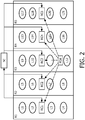
- Fig. 2 shows such as scenario with a PDA as wireless lighting switch.
- a lighting control system is installed in 5 rooms R1-R5. In each room, 4 wirelessly controllable luminaries L1-L4, L5-L8, L9-L12, L13-L16, L17-L21 and a room controller RC1-RC5 are installed. The room controller RC1-RC5 are connected to a system controller SC.
- the PDA is in the middle room R3 and executes a program for lighting system control.
- the program enables a user to wirelessly control luminaries L1-L21 of the lighting control system.
- the lighting control system must know in which the room the PDA actually is located.
- different technologies can be used, for example WiFiTM, Bluetooth®, ZigBeeTM.
- a user wishes to switch on the luminaries L9-L12 in room R3, he may press a button of the program for controlling the lighting on his PDA. This triggers the program to transmit a RF signal to the room controller RC1-RC5 for switching on luminaries in one of the rooms R1-R5.
- the invention can be applied to any networked control systems, particularly networked lighting control systems, where by means of an installation plan positions of devices such as luminaires and switches in rooms and the relative locations of the rooms are known.
- the invention can particularly be used to improve the commissioning of devices of a networked control system.
- the invention can help to reduce the commissioning effort and to remove errors.
- At least some of the functionality of the invention may be performed by hard- or software.
- a single or multiple standard microprocessors or microcontrollers may be used to process a single or multiple algorithms implementing the invention.
Landscapes
- Engineering & Computer Science (AREA)
- Computer Networks & Wireless Communication (AREA)
- Automation & Control Theory (AREA)
- Signal Processing (AREA)
- Physics & Mathematics (AREA)
- General Physics & Mathematics (AREA)
- Circuit Arrangement For Electric Light Sources In General (AREA)
- Selective Calling Equipment (AREA)
- Mobile Radio Communication Systems (AREA)
Claims (14)
- Procédé de mise en service automatique de dispositifs d'un système de commande en réseau, comprenant un ou plusieurs premiers dispositifs (S1-S3) et un ou plusieurs deuxièmes dispositifs (RC1-RC3) aptes à communiquer sans fil, dans lequel des signaux sans fil provenant de premiers dispositifs (S 1-S3) sont reçus par un ou plusieurs deuxièmes dispositifs (RC1-RC3) et, pour chaque signal sans fil reçu, la force de signal est déterminée, et dans lequel la mise en service comprend les étapes suivantes :- le traitement des forces de signal déterminées en tenant compte de contraintes dérivées d'une installation du système de commande en réseau pour une mise en service, et- l'assignation des premiers dispositifs (S1-S3) à un ou plusieurs des deuxièmes dispositifs (RC1-RC3) en fonction du résultat de traitement,caractérisé en ce que
l'étape du traitement comprend en outre la pondération de la force de signal de chaque signal sans fil reçu en fonction de l'installation. - Procédé selon la revendication 1, dans lequel l'installation du système de commande en réseau comprend une ou plusieurs pièces (R1-R3) et des contraintes dérivées du plan d'installation sont un ou plusieurs de ce qui suit :- un nombre de premiers dispositifs dans chaque pièce ;- un nombre de deuxièmes dispositifs dans chaque pièce ;- un nombre de pièces auxquelles un premier dispositif est assigné.
- Procédé selon la revendication 2, dans lequel l'étape du traitement comprend les étapes suivantes :- la détermination de la force de signal totale pour plusieurs assignations possibles différentes de premiers dispositifs et de deuxièmes dispositifs, respectant les contraintes dérivées de l'installation du système de commande en réseau, et- la sélection de l'assignation de premiers dispositifs et de deuxièmes dispositifs avec la plus grande force de signal totale parmi les forces de signal totales déterminées.
- Procédé selon la revendication 3, dans lequel l'étape de la détermination de la force de signal totale comprend une méthode de force brute sur toutes les permutations possibles d'allocations de premiers dispositifs et de deuxièmes dispositifs ou une méthode heuristique.
- Procédé selon la revendication 1, dans lequel les valeurs de pondération des forces de signal sont estimées sur la base de mesures réelles des forces de signal de signaux sans fil.
- Programme informatique permettant à un processeur d'effectuer un procédé selon l'une quelconque des revendications précédentes.
- Support d'enregistrement mémorisant un programme informatique selon la revendication 6.
- Ordinateur programmé pour effectuer un procédé selon l'une quelconque des revendications 1 à 5.
- Outil de mise en service (SC) pour un système de commande en réseau, comprenant- un module de communication (10) pour communiquer avec des dispositifs (RC1-RC3) du système de commande en réseau et recevoir, en provenance d'un ou plusieurs deuxièmes dispositifs (RC1-RC3), des forces de signal de signaux sans fil provenant de premiers dispositifs (S1-S3) reçus et déterminées par l'un ou plusieurs deuxièmes dispositifs, et- un processeur (12) configuré pour effectuer un procédé de mise en service afin d'assigner les premiers dispositifs (S1-S3) à un ou plusieurs des deuxièmes dispositifs (RC1-RC3), par l'exécution des étapes de :- le traitement des forces de signal déterminées en tenant compte de contraintes dérivées d'une installation du système de commande en réseau pour une mise en service, et- l'assignation des premiers dispositifs (S1-S3) à un ou plusieurs des deuxièmes dispositifs (RC1-RC3) en fonction du résultat de traitement,caractérisé en ce que
le traitement comprend en outre la pondération de la force de signal de chaque signal sans fil reçu en fonction de l'installation. - Système de commande en réseau comprenant :- un ou plusieurs premiers dispositifs (S1-S3),- un ou plusieurs deuxièmes dispositifs (RC1-RC3) aptes à recevoir des signaux sans fil en provenance de premiers dispositifs (S1-S3) et à déterminer, pour chaque signal sans fil reçu, la force de signal,- un organe de commande de système (SC) apte à effectuer :- la réception des forces de signal déterminées,- le traitement des forces de signal déterminées en tenant compte de contraintes dérivées d'une installation du système de commande en réseau pour une mise en service, et- l'assignation des premiers dispositifs (S1-S3) à un ou plusieurs des deuxièmes dispositifs (RC1-RC3) en fonction du résultat de traitement, caractérisé en ce quele traitement comprend la pondération de la force de signal de chaque signal sans fil reçu en fonction de l'installation.
- Système selon la revendication 10, étant un système de commande d'éclairage, dans lequel- l'un ou plusieurs premiers dispositifs (S1-S3) sont des commutateurs sans fil et/ou des ordinateurs aptes à communiquer sans fil avec des deuxièmes dispositifs,- les plusieurs deuxièmes dispositifs sont un organe de commande de pièce sans fil (RC1-RC3) et/ou des luminaires sans fil (L1-L18).
- Système selon la revendication 10, étant un système de commande d'éclairage, dans lequel les premiers dispositifs et les deuxièmes dispositifs sont des luminaires sans fil (L1-L18).
- Système selon la revendication 10, 11 ou 12, dans lequel l'organe de commande de système (SC) est intégré à un deuxième dispositif.
- Système selon l'une quelconque des revendications 10 à 13, dans lequel l'organe de commande de système est configuré pour effectuer un procédé selon l'une quelconque des revendications 1 à 6.
Priority Applications (1)
| Application Number | Priority Date | Filing Date | Title |
|---|---|---|---|
| EP12730644.7A EP2719257B1 (fr) | 2011-06-07 | 2012-06-05 | Mise en service automatique de dispositifs d'un système de commande en réseau |
Applications Claiming Priority (3)
| Application Number | Priority Date | Filing Date | Title |
|---|---|---|---|
| EP11168869 | 2011-06-07 | ||
| EP12730644.7A EP2719257B1 (fr) | 2011-06-07 | 2012-06-05 | Mise en service automatique de dispositifs d'un système de commande en réseau |
| PCT/IB2012/052823 WO2012168859A2 (fr) | 2011-06-07 | 2012-06-05 | Mise en service automatique de dispositifs d'un système de commande en réseau |
Publications (2)
| Publication Number | Publication Date |
|---|---|
| EP2719257A2 EP2719257A2 (fr) | 2014-04-16 |
| EP2719257B1 true EP2719257B1 (fr) | 2017-04-12 |
Family
ID=46397339
Family Applications (1)
| Application Number | Title | Priority Date | Filing Date |
|---|---|---|---|
| EP12730644.7A Active EP2719257B1 (fr) | 2011-06-07 | 2012-06-05 | Mise en service automatique de dispositifs d'un système de commande en réseau |
Country Status (6)
| Country | Link |
|---|---|
| US (1) | US9996057B2 (fr) |
| EP (1) | EP2719257B1 (fr) |
| JP (1) | JP6067688B2 (fr) |
| CN (1) | CN103563311B (fr) |
| RU (1) | RU2605347C2 (fr) |
| WO (1) | WO2012168859A2 (fr) |
Families Citing this family (23)
| Publication number | Priority date | Publication date | Assignee | Title |
|---|---|---|---|---|
| ES2752756T3 (es) | 2014-04-25 | 2020-04-06 | Signify Holding Bv | Acceso a iluminación basado en zonas |
| US10944837B2 (en) * | 2015-03-24 | 2021-03-09 | Carrier Corporation | Floor-plan based learning and registration of distributed devices |
| CN107667384A (zh) | 2015-03-24 | 2018-02-06 | 开利公司 | 基于楼层平面图覆盖的自动配对和参数设置 |
| DK3275204T3 (da) | 2015-03-24 | 2020-09-21 | Carrier Corp | System og fremgangsmåde til indsamling og analysering af flerdimensionel bygningsinformation |
| WO2016154311A1 (fr) | 2015-03-24 | 2016-09-29 | Carrier Corporation | Systèmes et procédés pour fournir une interface utilisateur graphique indiquant des niveaux de menace d'intrusion pour un bâtiment |
| CN107646118B (zh) | 2015-03-24 | 2022-04-15 | 开利公司 | 用于确定与楼层平面图相关的rf传感器性能的系统和方法 |
| WO2016154303A1 (fr) | 2015-03-24 | 2016-09-29 | Carrier Corporation | Système intégré pour la vente, installation et maintenance de systèmes de construction |
| US11036897B2 (en) | 2015-03-24 | 2021-06-15 | Carrier Corporation | Floor plan based planning of building systems |
| US10230326B2 (en) | 2015-03-24 | 2019-03-12 | Carrier Corporation | System and method for energy harvesting system planning and performance |
| WO2016150795A1 (fr) | 2015-03-26 | 2016-09-29 | Philips Lighting Holding B.V. | Mappage de dispositifs à des représentations dans un modèle |
| CN105021304A (zh) * | 2015-07-03 | 2015-11-04 | 江苏声立传感技术有限公司 | 电力开关柜触头测温应用中提高无源无线测温系统信号覆盖和质量的方法 |
| RU2719394C2 (ru) * | 2015-09-08 | 2020-04-17 | Филипс Лайтинг Холдинг Б.В. | Подключение световых устройств |
| CN108141943B (zh) * | 2015-09-18 | 2020-03-24 | 飞利浦照明控股有限公司 | 用于自动化的照明器材位置映射的系统和方法 |
| US9974146B2 (en) | 2015-09-25 | 2018-05-15 | General Electric Company | Commissioning method of lighting control system using visual light communication |
| US9949347B2 (en) | 2015-09-25 | 2018-04-17 | General Electric Company | System and processes for commissioning indoor industrial lighting |
| US10231297B2 (en) | 2015-11-24 | 2019-03-12 | Philips Lighting Holding B.V. | Lighting apparatus control switch and method |
| CN105515834B (zh) * | 2015-11-27 | 2019-02-22 | 小米科技有限责任公司 | 设备分组管理系统、方法及装置 |
| US10178739B2 (en) * | 2016-11-08 | 2019-01-08 | Zumtobel Lighting Inc. | Assigning controllable luminaire devices to control groups |
| JP6876982B2 (ja) * | 2017-07-03 | 2021-05-26 | パナソニックIpマネジメント株式会社 | 照明システムのペアリング方法および照明システム |
| US10470155B2 (en) | 2017-11-30 | 2019-11-05 | Abl Ip Holding Llc | Commissioning of an indoor positioning system using a secondary positioning system |
| CN109543968A (zh) * | 2018-11-08 | 2019-03-29 | 中建二局安装工程有限公司 | 一种建筑机电系统全过程综合调试方法 |
| US11553618B2 (en) | 2020-08-26 | 2023-01-10 | PassiveLogic, Inc. | Methods and systems of building automation state load and user preference via network systems activity |
| US12439500B2 (en) | 2020-09-21 | 2025-10-07 | Signify Holding B.V. | Methods and systems for commissioning devices |
Family Cites Families (27)
| Publication number | Priority date | Publication date | Assignee | Title |
|---|---|---|---|---|
| WO2007040398A1 (fr) * | 1995-07-03 | 2007-04-12 | Xanadu Wireless B.V. | Procede d'installation d'un composant de reseau sans fil |
| TW575828B (en) * | 2002-05-07 | 2004-02-11 | Giga Byte Tech Co Ltd | Method for directly displaying signal intensity and the device thereof |
| US7020442B2 (en) * | 2002-10-02 | 2006-03-28 | Csi Wireless Llc | System and method for WLAN signal strength determination |
| US7116988B2 (en) * | 2004-03-16 | 2006-10-03 | Airespace, Inc. | Location of wireless nodes using signal strength weighting metric |
| US7030761B2 (en) | 2004-03-16 | 2006-04-18 | Symbol Technologies | Multi-resolution object location system and method |
| KR20070121730A (ko) | 2005-03-11 | 2007-12-27 | 코닌클리즈케 필립스 일렉트로닉스 엔.브이. | 무선 조명 할당을 위한 벽 찾기 |
| WO2006095317A1 (fr) * | 2005-03-11 | 2006-09-14 | Koninklijke Philips Electronics N.V. | Mise en service de dispositifs reseau sans fil conformement a un plan d'installation |
| EP1862036B1 (fr) * | 2005-03-11 | 2008-12-31 | Koninklijke Philips Electronics N.V. | Groupage des noeuds d'un systeme d'eclairage sans fil en fonction de la disposition des pieces d'un batiment |
| US7400594B2 (en) * | 2005-05-03 | 2008-07-15 | Eaton Corporation | Method and system for automated distributed pairing of wireless nodes of a communication network |
| KR100714050B1 (ko) * | 2005-11-18 | 2007-05-04 | 린나이코리아 주식회사 | 분산형 홈 네트워크용 통합형 게이트웨이 및 이를 위한소프트웨어 프레임워크 구조 |
| EP1994686B1 (fr) * | 2006-03-06 | 2018-08-01 | Koninklijke Philips N.V. | Utilisation de position pour groupement de n uds |
| EP2039069B1 (fr) * | 2006-06-29 | 2017-04-05 | Philips Lighting Holding B.V. | Realisation et mise en service de reseaux limites autonomes |
| US7761119B2 (en) * | 2006-07-05 | 2010-07-20 | Kyocera Corporation | Signal strength annunciators for multi-mode wireless communication devices |
| US20080042803A1 (en) * | 2006-07-27 | 2008-02-21 | Joshua Posamentier | Adjusting signal strength used to detect tags |
| US8744391B2 (en) * | 2007-05-31 | 2014-06-03 | Motorola Mobility Llc | Signal strength indication methods for use in wireless communication devices |
| KR101405688B1 (ko) * | 2007-09-14 | 2014-06-12 | 엘지이노텍 주식회사 | 지그비 시스템 |
| EP2279591A2 (fr) | 2008-04-18 | 2011-02-02 | Philips Intellectual Property & Standards GmbH | Procédé de mise en service d'un agencement de dispositif |
| US20100114340A1 (en) * | 2008-06-02 | 2010-05-06 | Charles Huizenga | Automatic provisioning of wireless control systems |
| CN101686486A (zh) | 2008-09-27 | 2010-03-31 | 陕西浩瀚新宇科技发展有限公司 | 一种td-scdma家用基站的小区自配置方法 |
| US20100157848A1 (en) * | 2008-12-22 | 2010-06-24 | Qualcomm Incorporated | Method and apparatus for providing and utilizing local maps and annotations in location determination |
| US8180343B2 (en) * | 2009-02-26 | 2012-05-15 | Kyocera Corporation | Detection of wireless communication devices in systems having cells with different pilot signal frequencies |
| WO2010109361A1 (fr) * | 2009-03-23 | 2010-09-30 | Koninklijke Philips Electronics, N.V. | Système et procédé de détection d'emplacement avec prise d'empreinte |
| US9213324B2 (en) * | 2009-06-30 | 2015-12-15 | Koninklijke Philips N.V. | Systems and methods for managing interaction with controllable lighting networks |
| US8159156B2 (en) * | 2009-08-10 | 2012-04-17 | Redwood Systems, Inc. | Lighting systems and methods of auto-commissioning |
| US8503330B1 (en) * | 2010-03-05 | 2013-08-06 | Daintree Networks, Pty. Ltd. | Wireless system commissioning and optimization |
| US8422401B1 (en) * | 2010-05-11 | 2013-04-16 | Daintree Networks, Pty. Ltd. | Automated commissioning of wireless devices |
| US8890435B2 (en) * | 2011-03-11 | 2014-11-18 | Ilumi Solutions, Inc. | Wireless lighting control system |
-
2012
- 2012-06-05 WO PCT/IB2012/052823 patent/WO2012168859A2/fr not_active Ceased
- 2012-06-05 RU RU2013158702/08A patent/RU2605347C2/ru active
- 2012-06-05 US US14/119,253 patent/US9996057B2/en active Active
- 2012-06-05 JP JP2014514193A patent/JP6067688B2/ja active Active
- 2012-06-05 CN CN201280027556.9A patent/CN103563311B/zh active Active
- 2012-06-05 EP EP12730644.7A patent/EP2719257B1/fr active Active
Non-Patent Citations (1)
| Title |
|---|
| None * |
Also Published As
| Publication number | Publication date |
|---|---|
| RU2013158702A (ru) | 2015-07-20 |
| RU2605347C2 (ru) | 2016-12-20 |
| EP2719257A2 (fr) | 2014-04-16 |
| US20140088772A1 (en) | 2014-03-27 |
| CN103563311B (zh) | 2017-09-01 |
| JP6067688B2 (ja) | 2017-01-25 |
| CN103563311A (zh) | 2014-02-05 |
| JP2014519174A (ja) | 2014-08-07 |
| WO2012168859A2 (fr) | 2012-12-13 |
| US9996057B2 (en) | 2018-06-12 |
| WO2012168859A3 (fr) | 2013-01-31 |
Similar Documents
| Publication | Publication Date | Title |
|---|---|---|
| EP2719257B1 (fr) | Mise en service automatique de dispositifs d'un système de commande en réseau | |
| EP3406091B1 (fr) | Système de configuration pour un ensemble de dispositifs de réseau sans fil | |
| US8290437B2 (en) | Locating reference nodes for positioning devices in a wireless network | |
| CN101479995B (zh) | 自治的有限网络实现与试运转 | |
| US10412814B2 (en) | Occupancy and non-occupancy detection in the lighting system | |
| JP2014519174A5 (fr) | ||
| US11959994B2 (en) | Electronic apparatus, method, and electronic system | |
| WO2008129488A2 (fr) | Système et procédé pour le recalcul de probabilités dans des arbres de décision | |
| CN104202088A (zh) | 可见光通信方法及可见光通信装置 | |
| WO2019081359A1 (fr) | Installation d'un réseau de commande d'application au moyen d'une topologie automatiquement déterminée | |
| US11170296B2 (en) | System level occupancy counting in a lighting system | |
| KR20110082044A (ko) | 장치의 자동 할당을 위한 방법 및 장치 | |
| EP3672335B1 (fr) | Procédé et dispositif pour la mise en service d'un système d'éclairage | |
| US20170339583A1 (en) | System for rf quiet channel optimization | |
| EP3939339B1 (fr) | Commande ou mise en service d'une pluralité de noeuds à l'aide d'un dispositif mobile | |
| US11729592B2 (en) | Angle of arrival commissioning of lighting devices | |
| US20250168070A1 (en) | Commissioning device using a short-range signal | |
| CN112673713B (zh) | 用于调试光源的方法、系统、装置和计算机可读介质 | |
| EP4203623A1 (fr) | Commande d'éclairage | |
| JP5966668B2 (ja) | 位置情報管理システム、通信装置及び位置情報確認方法 |
Legal Events
| Date | Code | Title | Description |
|---|---|---|---|
| PUAI | Public reference made under article 153(3) epc to a published international application that has entered the european phase |
Free format text: ORIGINAL CODE: 0009012 |
|
| 17P | Request for examination filed |
Effective date: 20140107 |
|
| AK | Designated contracting states |
Kind code of ref document: A2 Designated state(s): AL AT BE BG CH CY CZ DE DK EE ES FI FR GB GR HR HU IE IS IT LI LT LU LV MC MK MT NL NO PL PT RO RS SE SI SK SM TR |
|
| DAX | Request for extension of the european patent (deleted) | ||
| RAP1 | Party data changed (applicant data changed or rights of an application transferred) |
Owner name: PHILIPS LIGHTING HOLDING B.V. |
|
| GRAP | Despatch of communication of intention to grant a patent |
Free format text: ORIGINAL CODE: EPIDOSNIGR1 |
|
| INTG | Intention to grant announced |
Effective date: 20161116 |
|
| GRAS | Grant fee paid |
Free format text: ORIGINAL CODE: EPIDOSNIGR3 |
|
| GRAA | (expected) grant |
Free format text: ORIGINAL CODE: 0009210 |
|
| AK | Designated contracting states |
Kind code of ref document: B1 Designated state(s): AL AT BE BG CH CY CZ DE DK EE ES FI FR GB GR HR HU IE IS IT LI LT LU LV MC MK MT NL NO PL PT RO RS SE SI SK SM TR |
|
| REG | Reference to a national code |
Ref country code: GB Ref legal event code: FG4D |
|
| REG | Reference to a national code |
Ref country code: CH Ref legal event code: EP |
|
| REG | Reference to a national code |
Ref country code: IE Ref legal event code: FG4D |
|
| REG | Reference to a national code |
Ref country code: AT Ref legal event code: REF Ref document number: 884971 Country of ref document: AT Kind code of ref document: T Effective date: 20170515 |
|
| REG | Reference to a national code |
Ref country code: DE Ref legal event code: R096 Ref document number: 602012031050 Country of ref document: DE |
|
| REG | Reference to a national code |
Ref country code: FR Ref legal event code: PLFP Year of fee payment: 6 |
|
| RIN2 | Information on inventor provided after grant (corrected) |
Inventor name: LELKENS, ARMAND, MICHEL, MARIE |
|
| REG | Reference to a national code |
Ref country code: NL Ref legal event code: MP Effective date: 20170412 |
|
| REG | Reference to a national code |
Ref country code: LT Ref legal event code: MG4D |
|
| REG | Reference to a national code |
Ref country code: AT Ref legal event code: MK05 Ref document number: 884971 Country of ref document: AT Kind code of ref document: T Effective date: 20170412 |
|
| PG25 | Lapsed in a contracting state [announced via postgrant information from national office to epo] |
Ref country code: NL Free format text: LAPSE BECAUSE OF FAILURE TO SUBMIT A TRANSLATION OF THE DESCRIPTION OR TO PAY THE FEE WITHIN THE PRESCRIBED TIME-LIMIT Effective date: 20170412 |
|
| PG25 | Lapsed in a contracting state [announced via postgrant information from national office to epo] |
Ref country code: FI Free format text: LAPSE BECAUSE OF FAILURE TO SUBMIT A TRANSLATION OF THE DESCRIPTION OR TO PAY THE FEE WITHIN THE PRESCRIBED TIME-LIMIT Effective date: 20170412 Ref country code: GR Free format text: LAPSE BECAUSE OF FAILURE TO SUBMIT A TRANSLATION OF THE DESCRIPTION OR TO PAY THE FEE WITHIN THE PRESCRIBED TIME-LIMIT Effective date: 20170713 Ref country code: LT Free format text: LAPSE BECAUSE OF FAILURE TO SUBMIT A TRANSLATION OF THE DESCRIPTION OR TO PAY THE FEE WITHIN THE PRESCRIBED TIME-LIMIT Effective date: 20170412 Ref country code: NO Free format text: LAPSE BECAUSE OF FAILURE TO SUBMIT A TRANSLATION OF THE DESCRIPTION OR TO PAY THE FEE WITHIN THE PRESCRIBED TIME-LIMIT Effective date: 20170712 Ref country code: ES Free format text: LAPSE BECAUSE OF FAILURE TO SUBMIT A TRANSLATION OF THE DESCRIPTION OR TO PAY THE FEE WITHIN THE PRESCRIBED TIME-LIMIT Effective date: 20170412 Ref country code: HR Free format text: LAPSE BECAUSE OF FAILURE TO SUBMIT A TRANSLATION OF THE DESCRIPTION OR TO PAY THE FEE WITHIN THE PRESCRIBED TIME-LIMIT Effective date: 20170412 Ref country code: AT Free format text: LAPSE BECAUSE OF FAILURE TO SUBMIT A TRANSLATION OF THE DESCRIPTION OR TO PAY THE FEE WITHIN THE PRESCRIBED TIME-LIMIT Effective date: 20170412 |
|
| PG25 | Lapsed in a contracting state [announced via postgrant information from national office to epo] |
Ref country code: IS Free format text: LAPSE BECAUSE OF FAILURE TO SUBMIT A TRANSLATION OF THE DESCRIPTION OR TO PAY THE FEE WITHIN THE PRESCRIBED TIME-LIMIT Effective date: 20170812 Ref country code: PL Free format text: LAPSE BECAUSE OF FAILURE TO SUBMIT A TRANSLATION OF THE DESCRIPTION OR TO PAY THE FEE WITHIN THE PRESCRIBED TIME-LIMIT Effective date: 20170412 Ref country code: LV Free format text: LAPSE BECAUSE OF FAILURE TO SUBMIT A TRANSLATION OF THE DESCRIPTION OR TO PAY THE FEE WITHIN THE PRESCRIBED TIME-LIMIT Effective date: 20170412 Ref country code: SE Free format text: LAPSE BECAUSE OF FAILURE TO SUBMIT A TRANSLATION OF THE DESCRIPTION OR TO PAY THE FEE WITHIN THE PRESCRIBED TIME-LIMIT Effective date: 20170412 Ref country code: RS Free format text: LAPSE BECAUSE OF FAILURE TO SUBMIT A TRANSLATION OF THE DESCRIPTION OR TO PAY THE FEE WITHIN THE PRESCRIBED TIME-LIMIT Effective date: 20170412 Ref country code: BG Free format text: LAPSE BECAUSE OF FAILURE TO SUBMIT A TRANSLATION OF THE DESCRIPTION OR TO PAY THE FEE WITHIN THE PRESCRIBED TIME-LIMIT Effective date: 20170712 |
|
| REG | Reference to a national code |
Ref country code: DE Ref legal event code: R097 Ref document number: 602012031050 Country of ref document: DE |
|
| PG25 | Lapsed in a contracting state [announced via postgrant information from national office to epo] |
Ref country code: MC Free format text: LAPSE BECAUSE OF FAILURE TO SUBMIT A TRANSLATION OF THE DESCRIPTION OR TO PAY THE FEE WITHIN THE PRESCRIBED TIME-LIMIT Effective date: 20170412 Ref country code: CZ Free format text: LAPSE BECAUSE OF FAILURE TO SUBMIT A TRANSLATION OF THE DESCRIPTION OR TO PAY THE FEE WITHIN THE PRESCRIBED TIME-LIMIT Effective date: 20170412 Ref country code: RO Free format text: LAPSE BECAUSE OF FAILURE TO SUBMIT A TRANSLATION OF THE DESCRIPTION OR TO PAY THE FEE WITHIN THE PRESCRIBED TIME-LIMIT Effective date: 20170412 Ref country code: SK Free format text: LAPSE BECAUSE OF FAILURE TO SUBMIT A TRANSLATION OF THE DESCRIPTION OR TO PAY THE FEE WITHIN THE PRESCRIBED TIME-LIMIT Effective date: 20170412 Ref country code: EE Free format text: LAPSE BECAUSE OF FAILURE TO SUBMIT A TRANSLATION OF THE DESCRIPTION OR TO PAY THE FEE WITHIN THE PRESCRIBED TIME-LIMIT Effective date: 20170412 Ref country code: DK Free format text: LAPSE BECAUSE OF FAILURE TO SUBMIT A TRANSLATION OF THE DESCRIPTION OR TO PAY THE FEE WITHIN THE PRESCRIBED TIME-LIMIT Effective date: 20170412 |
|
| REG | Reference to a national code |
Ref country code: CH Ref legal event code: PL |
|
| PLBE | No opposition filed within time limit |
Free format text: ORIGINAL CODE: 0009261 |
|
| STAA | Information on the status of an ep patent application or granted ep patent |
Free format text: STATUS: NO OPPOSITION FILED WITHIN TIME LIMIT |
|
| PG25 | Lapsed in a contracting state [announced via postgrant information from national office to epo] |
Ref country code: IT Free format text: LAPSE BECAUSE OF FAILURE TO SUBMIT A TRANSLATION OF THE DESCRIPTION OR TO PAY THE FEE WITHIN THE PRESCRIBED TIME-LIMIT Effective date: 20170412 Ref country code: SM Free format text: LAPSE BECAUSE OF FAILURE TO SUBMIT A TRANSLATION OF THE DESCRIPTION OR TO PAY THE FEE WITHIN THE PRESCRIBED TIME-LIMIT Effective date: 20170412 |
|
| 26N | No opposition filed |
Effective date: 20180115 |
|
| REG | Reference to a national code |
Ref country code: IE Ref legal event code: MM4A |
|
| PG25 | Lapsed in a contracting state [announced via postgrant information from national office to epo] |
Ref country code: LI Free format text: LAPSE BECAUSE OF NON-PAYMENT OF DUE FEES Effective date: 20170630 Ref country code: IE Free format text: LAPSE BECAUSE OF NON-PAYMENT OF DUE FEES Effective date: 20170605 Ref country code: CH Free format text: LAPSE BECAUSE OF NON-PAYMENT OF DUE FEES Effective date: 20170630 Ref country code: LU Free format text: LAPSE BECAUSE OF NON-PAYMENT OF DUE FEES Effective date: 20170605 |
|
| PG25 | Lapsed in a contracting state [announced via postgrant information from national office to epo] |
Ref country code: SI Free format text: LAPSE BECAUSE OF FAILURE TO SUBMIT A TRANSLATION OF THE DESCRIPTION OR TO PAY THE FEE WITHIN THE PRESCRIBED TIME-LIMIT Effective date: 20170412 |
|
| REG | Reference to a national code |
Ref country code: BE Ref legal event code: MM Effective date: 20170630 |
|
| REG | Reference to a national code |
Ref country code: FR Ref legal event code: PLFP Year of fee payment: 7 |
|
| PG25 | Lapsed in a contracting state [announced via postgrant information from national office to epo] |
Ref country code: BE Free format text: LAPSE BECAUSE OF NON-PAYMENT OF DUE FEES Effective date: 20170630 |
|
| PG25 | Lapsed in a contracting state [announced via postgrant information from national office to epo] |
Ref country code: MT Free format text: LAPSE BECAUSE OF NON-PAYMENT OF DUE FEES Effective date: 20170605 |
|
| PG25 | Lapsed in a contracting state [announced via postgrant information from national office to epo] |
Ref country code: HU Free format text: LAPSE BECAUSE OF FAILURE TO SUBMIT A TRANSLATION OF THE DESCRIPTION OR TO PAY THE FEE WITHIN THE PRESCRIBED TIME-LIMIT; INVALID AB INITIO Effective date: 20120605 |
|
| PG25 | Lapsed in a contracting state [announced via postgrant information from national office to epo] |
Ref country code: CY Free format text: LAPSE BECAUSE OF NON-PAYMENT OF DUE FEES Effective date: 20170412 |
|
| PG25 | Lapsed in a contracting state [announced via postgrant information from national office to epo] |
Ref country code: MK Free format text: LAPSE BECAUSE OF FAILURE TO SUBMIT A TRANSLATION OF THE DESCRIPTION OR TO PAY THE FEE WITHIN THE PRESCRIBED TIME-LIMIT Effective date: 20170412 |
|
| PG25 | Lapsed in a contracting state [announced via postgrant information from national office to epo] |
Ref country code: TR Free format text: LAPSE BECAUSE OF FAILURE TO SUBMIT A TRANSLATION OF THE DESCRIPTION OR TO PAY THE FEE WITHIN THE PRESCRIBED TIME-LIMIT Effective date: 20170412 |
|
| PG25 | Lapsed in a contracting state [announced via postgrant information from national office to epo] |
Ref country code: PT Free format text: LAPSE BECAUSE OF FAILURE TO SUBMIT A TRANSLATION OF THE DESCRIPTION OR TO PAY THE FEE WITHIN THE PRESCRIBED TIME-LIMIT Effective date: 20170412 |
|
| PG25 | Lapsed in a contracting state [announced via postgrant information from national office to epo] |
Ref country code: AL Free format text: LAPSE BECAUSE OF FAILURE TO SUBMIT A TRANSLATION OF THE DESCRIPTION OR TO PAY THE FEE WITHIN THE PRESCRIBED TIME-LIMIT Effective date: 20170412 |
|
| REG | Reference to a national code |
Ref country code: DE Ref legal event code: R082 Ref document number: 602012031050 Country of ref document: DE Representative=s name: MEISSNER BOLTE PATENTANWAELTE RECHTSANWAELTE P, DE Ref country code: DE Ref legal event code: R081 Ref document number: 602012031050 Country of ref document: DE Owner name: SIGNIFY HOLDING B.V., NL Free format text: FORMER OWNER: PHILIPS LIGHTING HOLDING B.V., EINDHOVEN, NL |
|
| P01 | Opt-out of the competence of the unified patent court (upc) registered |
Effective date: 20230421 |
|
| PGFP | Annual fee paid to national office [announced via postgrant information from national office to epo] |
Ref country code: GB Payment date: 20250617 Year of fee payment: 14 |
|
| PGFP | Annual fee paid to national office [announced via postgrant information from national office to epo] |
Ref country code: FR Payment date: 20250624 Year of fee payment: 14 |
|
| PGFP | Annual fee paid to national office [announced via postgrant information from national office to epo] |
Ref country code: DE Payment date: 20250827 Year of fee payment: 14 |